JP4155546B2 - Spherical ultrasonic motor - Google Patents
Spherical ultrasonic motor Download PDFInfo
- Publication number
- JP4155546B2 JP4155546B2 JP2001254243A JP2001254243A JP4155546B2 JP 4155546 B2 JP4155546 B2 JP 4155546B2 JP 2001254243 A JP2001254243 A JP 2001254243A JP 2001254243 A JP2001254243 A JP 2001254243A JP 4155546 B2 JP4155546 B2 JP 4155546B2
- Authority
- JP
- Japan
- Prior art keywords
- spherical
- ultrasonic motor
- stator
- sphere
- rotor
- Prior art date
- Legal status (The legal status is an assumption and is not a legal conclusion. Google has not performed a legal analysis and makes no representation as to the accuracy of the status listed.)
- Expired - Fee Related
Links
Images


Description
【0001】
【発明の属する技術分野】
本発明は、従来になく高い動作自由度を確保することのできる球面超音波モータに関し、特に、ロボットの関節部分の駆動源や視覚センサの向きを変える駆動源等として好適な、磁化球を用いた球面超音波モータに関する。
【0002】
【従来の技術】
近年、高度な制御部や各種センサを搭載したロボット製品が開発され、家庭用ロボットの時代が予感されるに至った。しかしながら、多くの関節に多自由度を必要とする人型ロボットにおける、手、足、その他の関節部、眼球部などに搭載するアクチュエータの出力と自由度は未だ不十分である。特に、従来から使用されている電磁モータは小型化すればする程、単位体積当たりの出力換算が需要を満たさなくなる。
【0003】
そこで近年は、電磁モータの代りに超音波アクチュエータを使用することが提案されている。特に圧電現象を駆動源とした直接駆動型アクチュエータである進行波型超音波モータは、磁界の影響を受けない上、摩擦駆動である為に慣性負荷を直接駆動することができる。また、電力停止時にその摩擦によって、高い保持トルクを発生することが出来る上、低速時のトルクが高く簡単な構造でトルク密度が高いという特徴がある。従って、進行波型超音波モータは、単位体積当たりの出力換算では電磁モータを上回る上、理論的な位置分析能は無限大であるという利点がある。そして、ロボットアームの高精度位置決めなどには、上記保持トルク、分解能、出力密度は重要なパラメータである。
【0004】
実際、本発明者等が開発した進行波型超音波モータである多自由度球面超音波モータは、単体で3自由度駆動が可能であり、超音波モータとしての動力特性を維持したまま、直接駆動方式で球体駆動操作を行うことが出来るので、人型ロボットの関節部のアクチュエータ等として好適である。そこで近年、球状ロータの球面に磁石(又は電磁石)を埋め込み、ホール素子を用いて磁力を検出することにより位置決めする、球面超音波アクチュエータが積極的に開発されている(例えば、特開平6−210585号、同7−80793号、同7−087764号、同7−087766号、同8−088987号、同8−132382号、同9−238485号各公報)。しかしながら、これらの場合には、何れかの方法でホール素子を球中心に配する必要があるため、支柱を立てるなどする必要があり、球の可動範囲を小さくするという欠点があった。このような欠点を解決する為に、球の外表面近傍にホール素子を配した場合には、必要とされるホール素子の数が多くなる為に位置決めの計算が複雑となり、位置決め精度が落ちるという欠点があった。
【0005】
一方、球状磁石の磁界をホール素子を用いて検出し、球の回転を測定することが出来ることは知られている(例えば、川北和明等、「玉軸受けの玉の運動検出に与える玉の磁化方法の影響」、トライボロジー会議予稿集、(1998)、川北和明等、「玉軸受けにおける玉の自転角速度の三次元ベクトル成分の解析」、潤滑第31巻第5号、(1986)、今戸啓二等、「ホール素子による玉軸受の玉の運動計測法に関する誤差の検討」、日本機械学会論文集(C編)65巻、634号、1999−6、今戸啓二等、「ホール素子による玉軸受の玉の運動測定法に関する一考察」。日本機械学会論文集(C編)65巻、612号、1997−8)。
【0006】
本発明者等は、球状磁石をロータとし、中心部にホール素子を有するステータを3箇以上使用して前記球状ロータを支持した場合には、球の可動範囲を限定することがない上、少ない数のホール素子で十分に位置検出を行うことのできる球面超音波モータとなること、及び、球状磁石の材質として、フェリ磁性体及び/又は強磁性体と非磁性体との均一混合物を用いた場合には、外部から磁性体が接近した場合の影響が少なくなる上球状磁石の磁束密度も高くすることができるので、更に高性能な球面超音波モータとすることが出来ることを見出し、本発明に到達した。
【0007】
【発明が解決しようとする課題】
従って本発明の目的は、従来になく高い動作自由度を有し、ロボットの関節部等の駆動装置として好適な球面超音波モータを提供することにある。
【0008】
【課題を解決するための手段】
本発明の上記の目的は、全体が磁化されている球状磁石をロータとし、該ロータを安定に支持する如く少なくとも3ヶ所に配されたステータを、該ステータに発生させた進行波によって前記ロータを回転させ得る如く枠体内に拘束し一体化させてなる超音波モータであって、前記ステータの中心部に、該球状磁石の磁界状態を検出する磁界検出手段を配してなることを特徴とする球面超音波モータによって達成された。
【0009】
【発明の実施の形態】
以下本発明を図面を用いて説明する。図1は、本発明で使用する球状磁石における磁界イメージ図である。本図の場合には球面と対応する一様な磁界が示されているが、この球体に適宜穴を設けたり、後述するような金属以外の素材を用いる場合には、その素材の構成を場所によって変えることにより、一様でない磁界を発生させても良い。尚、本発明における球状磁石は真球であることが好ましいが、極端でない限り楕円形状であっても良い。
【0010】
本発明においては、球状磁石からなるロータを複数のステータで保持し、該ステータを枠体内に拘束することによって一体化した超音波モータとする。球状ロータをステータで保持する手段、及び、該ステータを枠体に拘束する手段は公知の手段の中から適宜選択して用いることが出来るが、本発明においては、特にステータを、バネその他の弾性体を介して枠体に拘束することが、ステータの首振り運動を簡単な機構で可能とし、ステータとロータの密着を常に確保する上から好ましい。
本発明において、ステータを、弾性体を介して枠体内に拘束するに際しては、弾性体を枠体内にボルト等の固着手段によって枠体に固定する方法の他に、弾性体同士の距離が一定になるように結合し、ステータに球状ロータを保持させた全体を形状が不変の枠体に収納したり、枠体に設けた凹凸によって弾性体の位置を固定することにより、上記したボルト等による固定を不要とすることも可能である。
【0011】
また、磁界検出手段に関しては、枠体に、先端が球体表面に近接するアームを設け、該アームの先端に公知の磁界検 出手段を配することも出来るが、前記した如く、ステータと枠体の間には弾性体等が介在するので、枠体と球体の距離は一定とはならない。従って本発明においては、球体との距離が常に一定となるステータの中心部に前記磁界検出手段を配する。これによって、磁界の強さのみならず、その状態を正確に検出することができるので、球状磁石の位置決めの為の情報を得ることが出来る。
【0012】
本発明においては、非接触、小型、軽量且つ高感度である上安価であるという観点から、上記磁界検出手段としてホール素子を使用することが好ましい。前記したように、磁気検出手段はステータの中心に埋め込む。
【0013】
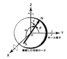
本発明における球体運動の三次元測定原理は以下の通りである。先ず、球状磁石とホール素子との位置関係、磁極位置へのパラメータを図2のように設定する。即ち、球状磁石の中心を原点とする絶対座標を考え、その各軸上に、球中心から一定の距離にホール素子を設置する。球状磁石が回転すると磁界も球と共に回転するので、各軸上のホール素子を通過する磁束も変化する。従って、各軸上の現磁束の方向を出力電圧から得ることが出来る。
【0014】
磁束の計測は直交座標系の軸上で行われるので、各軸上のホール素子による検出結果は、下記のようになる。
VxH=Vx0cosα
VyH=Vy0cosβ
VzH=Vz0cosγ
ここで、α、β、γは夫々磁界と各軸の座標軸とのなす角であり、Vx0、Vy0、Vz0は最大出力電圧である。これらの角度を用いることによって、球体の磁極位置ベクトル(ここではN極の位置ベクトル)は、rを球の半径として、次式で与えられる。

【0015】
本発明で使用する球状磁石の材質は、磁化が可能である限り特に限定されるものではないが、特にフェリ磁性体及び/又は強磁性体と非磁性体の均一混合物が好ましい。フェリ磁性体や強磁性体の含有量は適宜設定することが出来る。非磁性材料としては特にプラスチックが好ましく、中でもナイロン等のポリアミド樹脂が好ましい。このような素材は、金属材料に比べて加工が容易であるだけでなく、金属よりも大きな磁束密度を持たせることができ、また軽量でもある。
更に、一様に磁化された磁化球を得ることが出来るだけでなく、非磁性体の含有率の異なる複数の混合物を用いることによって、球体の磁束密度分布を適宜設計することも容易である。
【0016】
また、均一な材質の球体であっても、適宜穴をあけることにより、磁化球としての磁化の対称性を崩すことが出来る。このようにすることの利点は、磁化の対称性が良過ぎる為に球体が回転してもホール素子によって測定される磁界の強さや状態に変化が生じないことがあり、その為に事実上球体の位置決めが出来なくなるという場合が発生することを防止することが出来る点である。磁束密度分布の対称性を崩すことにより前記した三次元測定原理を利用することが出来なくなるが、磁界(磁束密度分布)と球の位置(角度)を予め導出したり、コンピュータに記憶させるなどすることにより関係付けることにより、三次元測定が可能となる。
【0017】
球体の磁化は、該球体を磁化用コイルの中心に置き、2本の鉄芯によってこれを挟み、コイルに電流を流すことによって行うことが出来る。この場合の鉄芯と球体の接触状態によって、点接触磁化法、面接触磁化法、及び非接触磁化法に分類することが出来る。点接触磁化法の場合には接触部に磁束が集中するので球体の中心軸付近が強く磁化されるが、その他の場合には一様に磁化される。
【0018】
本発明で使用するステータは、前記球状磁石表面との接触が緊密であり圧電体によって誘起される進行波のエネルギーがロータに効率良く伝達される限り、その形状は問われない。球体が回転しても上記進行波エネルギーの伝達効率が低下しないことが好ましい。従って、球体は真球性が高い程良い。但し、ステータのロータとの接触面については、櫛歯状等、適宜エネルギー伝達効率を向上させられるように調整することが出来る。また、ステータの形状は通常円板状であるが、貼着する圧電体は円環状であることが好ましい。この場合、円環の半径が大きくなる程駆動し易くなるものの、実際に関節部分等に使用した場合には、関節の動き得る自由度を制限することになるので、モータとしての要求性能に合わせてステータの大きさを適宜設計する必要がある。
【0019】
必要に応じて、1つのステータ中に、径の異なる円環状の圧電体を2以上配しても良い。この場合には、各ステータの進行波が協同して球体の回転に寄与するように同期を取ったり、同期をずらしてブレーキをかけたりする必要があることは当然である。尚、ステータ裏面の圧電素子やその貼着方法、電圧印加の為の配線等は、公知の如く行えば良い。
【0020】
【発明の効果】
本発明の球面超音波モータにおいては、ロータである球体がステータのみによって安定に支持され支柱等を必要としないので、ロータの回転自由度が従来の球面超音波モータに比較して各段に改善される。また、磁気検出手段をステータの中心に搭載させるので小型化も容易である。更に、磁化球としてフェリ磁性体及び/又は強磁性体と非磁性体との均一混合物を用いることにより、外部磁性体の影響を著しく低減することが出来る等、超音波モータとしての性能を更に改善する事が出来る。
以下、本発明を実施例によって更に詳述するが、本発明はこれによって限定されるものではない。
【0021】
【実施例】
実施例1.
図4は、4個のステータによって球状磁石であるロータ(球体ロータ)が保持されている場合の本発明の球面超音波モータの図である。この球面超音波モータは球体ロータを3自由度に駆動する事が出来る3自由度型の球面超音波モータである。縁端部が櫛歯状となっているステータは図5に示されており、ステータの中心部にはホール素子が配されている。
【0022】
球面超音波モータの全体は、JIS規格C3206系の快削黄銅を用いた。但し、球体ロータはフェライト−ナイロン6混合材(フェライト:ナイロン6の重量比は7:3)を用い、皿バネにはJIS規格SUS420J2を用いた。球体の保持はステータのみにより、球体保持の為のアングル等は全く使用されていない。また、ステータは板弾性体によって枠体に取付けられており、全体が一体化されているので、ステータは枠体に対して首振り運動することが可能である。従って、枠体とロータの間の距離は一定ではないが、ホール素子はステータ自身に埋め込まれているので、ホール素子と磁化球との距離が変わることはない。しかしながら、これによって、前記【0012】の前提が崩れるので、新たな方法として、ホール素子を取りつけた位置、及び、ホール素子からの出力電圧と磁極位置の内積を用い、4個のホール素子によって球状磁石の磁極位置を導出する。
【0023】
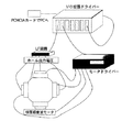
上記のようにして導出した磁極位置は球体の姿勢であるから、これをコンピュータによって制御することにより、三次元動作をさせることが出来る。その為のシステム図は図6に示した通りである。三次元動作としては関節の動作のみならず、眼球の動作等もある。
【0024】
実施例2.
夫々、直径45mmのベアリング球(鋼球)とフェライト−ナイロン6(重量比:7/3)の混合球を磁化し、得られた各磁化球について評価した。評価は、図7の如く、各磁化球の磁極におけるホール素子の出力を測定すると共に、直径47mmで長さ60mmの円柱、及び、直系30mmの球の2種類の磁性体(鋼)を各磁化球に接近させた時のホール素子の出力を測定する(図8)ことによって行った。
結果は、下記表1及び表2に示した通りである。
【表1】
表1、2より、共通して次のようなことが言える。
(1)同一条件で磁化を行った場合、ベアリング球とフェライト−ナイロン6混合球とでは、フェライト−ナイロン6混合球の方が約4倍の磁束密度の磁石となる。
(2)外乱として磁性体を近づけた場合、ホール素子の出力変動は、フェライト−ナイロン6混合球の方が遥かに小さく、位置(角度)検出時に外乱に対しての誤差が小さくなる。
【図面の簡単な説明】
【図1】球状磁石における磁界イメージ図である。
【図2】着磁したロータの磁極位置のパラメータを示す図である。
【図3】ステータの形状の例を示す図である。
【図4】本発明の球面超音波モータの外観の1例である。
【図5】図4の球面超音波モータに使用しているステータの内側を示す図である。
【図6】本発明の球面超音波モータをコンピュータ制御する時のシステム図である。
【図7】磁化球の評価の為のホール素子による測定位置を示す概念図である。
【図8】磁化球に磁性体を近づけた場合の影響をホール素子を用いて評価する時の、夫々の相対位置を表す概念図である。[0001]
BACKGROUND OF THE INVENTION
The present invention related to the spherical ultrasonic motor capable of ensuring a high operating flexibility than ever, especially suitable as a driving source such as changing the drive source and the orientation of the visual sensor of the joint portion of the robot, the magnetization sphere The present invention relates to a spherical ultrasonic motor using the above .
[0002]
[Prior art]
In recent years, robot products equipped with advanced control units and various sensors have been developed, and the era of home robots has been foreseen. However, in a humanoid robot that requires many degrees of freedom for many joints, the output and degree of freedom of actuators mounted on hands, feet, other joints, eyeballs, etc. are still insufficient. In particular, as the electromagnetic motor conventionally used becomes smaller, the output conversion per unit volume does not satisfy the demand.
[0003]
Therefore, in recent years, it has been proposed to use an ultrasonic actuator instead of an electromagnetic motor. In particular, a traveling wave type ultrasonic motor, which is a direct drive type actuator using a piezoelectric phenomenon as a drive source, is not affected by a magnetic field and can directly drive an inertial load because it is friction driven. In addition, a high holding torque can be generated by the friction when the electric power is stopped, and the torque density at a low speed is high and the torque density is high with a simple structure. Therefore, the traveling wave type ultrasonic motor has an advantage that the theoretical position analysis ability is infinite in addition to exceeding the electromagnetic motor in terms of output per unit volume. The holding torque, resolution, and output density are important parameters for high-precision positioning of the robot arm.
[0004]
In fact, the multi-degree-of-freedom spherical ultrasonic motor, which is a traveling wave type ultrasonic motor developed by the present inventors, can be driven by itself with three degrees of freedom, and directly while maintaining the power characteristics as an ultrasonic motor. Since the sphere driving operation can be performed by the driving method, it is suitable as an actuator for a joint portion of a humanoid robot. Therefore, in recent years, a spherical ultrasonic actuator has been actively developed in which a magnet (or an electromagnet) is embedded in the spherical surface of a spherical rotor, and positioning is performed by detecting magnetic force using a Hall element (for example, JP-A-6-210585). No. 7-80793, No. 7-087764, No. 7-087766, No. 8-088987, No. 8-132382, No. 9-238485). However, in these cases, since it is necessary to arrange the Hall element at the center of the sphere by any method, it is necessary to stand up the column, and there is a disadvantage that the movable range of the sphere is reduced. In order to solve such drawbacks, when hall elements are arranged in the vicinity of the outer surface of the sphere, the number of hall elements required increases, so that the calculation of positioning becomes complicated, and the positioning accuracy decreases. There were drawbacks.
[0005]
On the other hand, it is known that the magnetic field of a spherical magnet can be detected using a Hall element, and the rotation of a sphere can be measured (for example, Kazuaki Kawakita et al. Influence of Magnetization Method ”, Tribology Conference Proceedings, (1998), Kazuaki Kawakita, et al.,“ Analysis of 3D Vector Component of Ball Rotational Angular Velocity in Ball Bearing ”, Lubrication Vol. 31, No. 5, (1986), Imado Keiji et al., "Examination of errors in ball motion measurement method of ball bearings using Hall elements", The Japan Society of Mechanical Engineers, Vol. 65, 634, 1999-6, Keiji Imado, etc., "Ball bearings using Hall elements A Consideration on the Method of Measuring the Movement of Nodama ". Proceedings of the Japan Society of Mechanical Engineers (C) 65, 612, 1997-8).
[0006]
In the case where the spherical rotor is supported by using three or more stators each having a spherical magnet as a rotor and having a hall element in the center, the present inventors do not limit the movable range of the sphere, and the number is small. A spherical ultrasonic motor capable of sufficiently performing position detection with a number of Hall elements, and a uniform mixture of a ferrimagnetic material and / or a ferromagnetic material and a nonmagnetic material was used as the material of the spherical magnet. In this case, the magnetic flux density of the spherical magnet can be increased because the influence when the magnetic body approaches from the outside can be increased, and it has been found that a higher performance spherical ultrasonic motor can be obtained. Reached.
[0007]
[Problems to be solved by the invention]
Accordingly purpose of the present invention has a high operating flexibility than ever, to provide a suitable spherical ultrasonic motor as a drive device of a joint portion or the like of the robot.
[0008]
[Means for Solving the Problems]
The above purpose of the present invention is entirely the rotor spherical magnets are magnetized, the rotor and stator disposed in at least three places as supporting the rotor stably, by traveling wave generated on the stator an ultrasonic motor is constrained to as frame body capable of rotating made by integrating, in the center of the front Symbol stator, characterized by being arranged magnetic field detection means for detecting the magnetic field state of the spherical magnet And achieved by a spherical ultrasonic motor.
[0009]
DETAILED DESCRIPTION OF THE INVENTION
The present invention will be described below with reference to the drawings. FIG. 1 is a magnetic field image diagram of a spherical magnet used in the present invention. In the case of this figure, a uniform magnetic field corresponding to the spherical surface is shown. However, when a hole other than the sphere is appropriately provided or a material other than metal as described later is used, the configuration of the material is By changing according to the above, a non-uniform magnetic field may be generated. The spherical magnet in the present invention is preferably a true sphere, but may be elliptical as long as it is not extreme.
[0010]
In the present invention, an ultrasonic motor integrated by holding a rotor composed of spherical magnets with a plurality of stators and restraining the stator in a frame. Means to retain the spherical rotor in the stator, and the means for constraining the stator frame but can be suitably selected from known means, in the present invention, the scan stator in particular, the spring other of it is constrained to the frame via an elastic body, to allow the swinging movement of the stator with a simple mechanism, preferably from top to always ensure adhesion of the stator and the rotor.
In the present invention, the stator and, when the restraining inside the frame via a resilient member, the other ways of securing the elastic body to the frame body by a fixing means such as bolts inside the frame, the constant distance between the elastic member The whole structure in which the spherical rotor is held by the stator is housed in a frame whose shape remains unchanged, or the position of the elastic body is fixed by the unevenness provided in the frame, thereby fixing with the bolts described above. Can be eliminated.
[0011]
As for the magnetic field detection means, an arm whose tip is close to the surface of the sphere can be provided in the frame, and a known magnetic field detection means can be arranged at the tip of the arm. Since an elastic body or the like is interposed between the frames, the distance between the frame and the sphere is not constant. In the present invention, therefore, that high-speed steel of the magnetic field detector in the center of the stator where the distance between the spheres is always constant. As a result, not only the strength of the magnetic field but also its state can be accurately detected, so that information for positioning the spherical magnet can be obtained.
[0012]
In the present invention, it is preferable to use a Hall element as the magnetic field detecting means from the viewpoint of non-contact, small size, light weight, high sensitivity and low cost. As described above, the magnetic detection means write no buried in the center of the stay data.
[0013]
The principle of three-dimensional measurement of spherical motion in the present invention is as follows. First, the positional relationship between the spherical magnet and the Hall element and the parameters to the magnetic pole position are set as shown in FIG. That is, the absolute coordinates with the center of the spherical magnet as the origin are considered, and the Hall element is installed on each axis at a certain distance from the center of the sphere. When the spherical magnet rotates, the magnetic field also rotates with the sphere, so that the magnetic flux passing through the Hall element on each axis also changes. Therefore, the direction of the current magnetic flux on each axis can be obtained from the output voltage.
[0014]
Since the magnetic flux is measured on the axes of the orthogonal coordinate system, the detection results by the Hall elements on each axis are as follows.
V xH = V x0 cos α
V yH = V y0 cos β
V zH = V z0 cosγ
Here, α, β, and γ are angles formed between the magnetic field and the coordinate axes of the respective axes, and V x0 , V y0 , and V z0 are maximum output voltages. By using these angles, the magnetic pole position vector of the sphere (here, the N-pole position vector) is given by the following equation, where r is the radius of the sphere.
[0015]
The material of the spherical magnet used in the present invention is not particularly limited as long as it can be magnetized, but a ferrimagnetic material and / or a uniform mixture of a ferromagnetic material and a nonmagnetic material is particularly preferable. The content of the ferrimagnetic material or the ferromagnetic material can be set as appropriate. As the nonmagnetic material, plastic is particularly preferable, and polyamide resin such as nylon is particularly preferable. Such a material is not only easier to process than a metal material, but also can have a higher magnetic flux density than a metal, and is also lightweight.
Furthermore, it is possible not only to obtain a uniformly magnetized magnetized sphere, but also to easily design the magnetic flux density distribution of the sphere by using a plurality of mixtures having different nonmagnetic content.
[0016]
Moreover, even if it is a sphere of a uniform material, the symmetry of magnetization as a magnetized sphere can be broken by appropriately making holes. The advantage of doing this is that the symmetry of the magnetization is too good so that even if the sphere rotates, the strength and state of the magnetic field measured by the Hall element may not change. It is possible to prevent the occurrence of the case where the positioning of the lens cannot be performed. The above three-dimensional measurement principle cannot be used by breaking the symmetry of the magnetic flux density distribution. However, the magnetic field (magnetic flux density distribution) and the position (angle) of the sphere are derived in advance or stored in a computer. By associating with each other, three-dimensional measurement becomes possible.
[0017]
Magnetization of the sphere can be performed by placing the sphere at the center of the magnetizing coil, sandwiching it between two iron cores, and passing a current through the coil. In this case, the contact state between the iron core and the sphere can be classified into a point contact magnetization method, a surface contact magnetization method, and a non-contact magnetization method. In the case of the point contact magnetization method, since the magnetic flux concentrates on the contact portion, the vicinity of the center axis of the sphere is strongly magnetized, but in other cases, it is uniformly magnetized.
[0018]
The shape of the stator used in the present invention is not limited as long as the contact with the surface of the spherical magnet is close and the energy of the traveling wave induced by the piezoelectric body is efficiently transmitted to the rotor. It is preferable that the traveling wave energy transmission efficiency does not decrease even when the sphere rotates. Therefore, the higher the sphericity, the better the sphere. However, the contact surface of the stator with the rotor can be adjusted appropriately so as to improve the energy transmission efficiency, such as a comb-like shape. Moreover, although the shape of a stator is a disk shape normally, it is preferable that the piezoelectric body to stick is annular. In this case, the larger the radius of the ring, the easier it is to drive, but when it is actually used in a joint part, etc., the degree of freedom in which the joint can move is limited, so it matches the required performance as a motor. Therefore, it is necessary to appropriately design the size of the stator.
[0019]
If necessary, two or more annular piezoelectric bodies having different diameters may be arranged in one stator. In this case, it is natural that it is necessary to synchronize so that the traveling waves of the stators cooperate and contribute to the rotation of the sphere, or to apply the brake by shifting the synchronization. Incidentally, the piezoelectric element on the back surface of the stator, its attaching method, wiring for applying voltage, and the like may be performed in a known manner.
[0020]
【The invention's effect】
In the spherical ultrasonic motor of the present invention, the rotor sphere is stably supported only by the stator and does not require a support or the like, so the rotational degree of rotation of the rotor is improved in each stage compared to the conventional spherical ultrasonic motor. Is done. Further, miniaturization of the magnetic detection means Ru is mounted in the center of the stator is also easy. Furthermore, by using a ferrimagnetic material and / or a uniform mixture of a ferromagnetic material and a nonmagnetic material as the magnetized sphere, the influence of the external magnetic material can be remarkably reduced. I can do it.
EXAMPLES Hereinafter, although an Example demonstrates this invention further in full detail, this invention is not limited by this.
[0021]
【Example】
Example 1.
FIG. 4 is a diagram of the spherical ultrasonic motor of the present invention in the case where a rotor (spherical rotor) that is a spherical magnet is held by four stators. This spherical ultrasonic motor is a three-degree-of-freedom spherical ultrasonic motor that can drive a spherical rotor with three degrees of freedom. FIG. 5 shows a stator having a comb-teeth edge, and a hall element is arranged at the center of the stator.
[0022]
JIS standard C3206 series free-cutting brass was used for the entire spherical ultrasonic motor. The spherical rotor was a ferrite-nylon 6 mixed material (ferrite: nylon 6 weight ratio was 7: 3), and the disc spring was JIS standard SUS420J2. The sphere is held only by the stator, and the angle for holding the sphere is not used at all. Further, since the stator is attached to the frame body by a plate elastic body and integrated as a whole, the stator can swing with respect to the frame body. Accordingly, although the distance between the frame and the rotor is not constant, the distance between the Hall element and the magnetized sphere does not change because the Hall element is embedded in the stator itself. However, this breaks the premise of the above [0012]. As a new method, the position where the Hall element is attached and the inner product of the output voltage from the Hall element and the magnetic pole position are used. The magnetic pole position of the magnet is derived.
[0023]
Since the magnetic pole position derived as described above is the attitude of the sphere, the three-dimensional operation can be performed by controlling it with a computer. The system diagram for this is as shown in FIG. The three-dimensional motion includes not only joint motion but also eyeball motion.
[0024]
Example 2
Each of the obtained magnetized balls was evaluated by magnetizing a mixed ball of 45 mm diameter bearing ball (steel ball) and ferrite-nylon 6 (weight ratio: 7/3). In the evaluation, as shown in FIG. 7, the output of the Hall element at the magnetic pole of each magnetized sphere was measured, and two types of magnetic bodies (steel) of 47 mm in diameter and 60 mm in length and a direct 30 mm sphere were magnetized. This was done by measuring the output of the Hall element when approaching the sphere (FIG. 8).
The results are as shown in Tables 1 and 2 below.
[Table 1]
From Tables 1 and 2, the following can be said in common.
(1) When magnetization is performed under the same conditions, the ferrite-nylon 6 mixed sphere is a magnet having a magnetic flux density about four times that of the bearing sphere and the ferrite-nylon 6 mixed sphere.
(2) When a magnetic body is brought close as a disturbance, the output fluctuation of the Hall element is much smaller in the ferrite-nylon 6 mixed sphere, and the error with respect to the disturbance becomes small when the position (angle) is detected.
[Brief description of the drawings]
FIG. 1 is an image diagram of a magnetic field in a spherical magnet.
FIG. 2 is a diagram showing parameters of magnetic pole positions of a magnetized rotor.
FIG. 3 is a diagram showing an example of the shape of a stator.
FIG. 4 is an example of an appearance of a spherical ultrasonic motor of the present invention.
5 is a view showing the inside of a stator used in the spherical ultrasonic motor of FIG. 4. FIG.
FIG. 6 is a system diagram when the spherical ultrasonic motor of the present invention is controlled by a computer.
FIG. 7 is a conceptual diagram showing a measurement position by a Hall element for evaluation of a magnetized sphere.
FIG. 8 is a conceptual diagram showing a relative position when an influence when a magnetic body is brought close to a magnetized sphere is evaluated using a Hall element.
Claims (7)
Priority Applications (1)
| Application Number | Priority Date | Filing Date | Title |
|---|---|---|---|
| JP2001254243A JP4155546B2 (en) | 2001-08-24 | 2001-08-24 | Spherical ultrasonic motor |
Applications Claiming Priority (1)
| Application Number | Priority Date | Filing Date | Title |
|---|---|---|---|
| JP2001254243A JP4155546B2 (en) | 2001-08-24 | 2001-08-24 | Spherical ultrasonic motor |
Publications (3)
| Publication Number | Publication Date |
|---|---|
| JP2003070272A JP2003070272A (en) | 2003-03-07 |
| JP2003070272A5 JP2003070272A5 (en) | 2005-07-14 |
| JP4155546B2 true JP4155546B2 (en) | 2008-09-24 |
Family
ID=19082431
Family Applications (1)
| Application Number | Title | Priority Date | Filing Date |
|---|---|---|---|
| JP2001254243A Expired - Fee Related JP4155546B2 (en) | 2001-08-24 | 2001-08-24 | Spherical ultrasonic motor |
Country Status (1)
| Country | Link |
|---|---|
| JP (1) | JP4155546B2 (en) |
Families Citing this family (4)
| Publication number | Priority date | Publication date | Assignee | Title |
|---|---|---|---|---|
| JP2008122008A (en) * | 2006-11-14 | 2008-05-29 | Toshiba Corp | Gimbal device for target acquisition |
| JP4398990B2 (en) * | 2007-03-28 | 2010-01-13 | 株式会社東芝 | Drive mechanism |
| CN113726099B (en) * | 2021-08-10 | 2022-06-21 | 华中科技大学 | Multi-degree-of-freedom attitude measurement system and method for spherical motor |
| CN114715369B (en) * | 2022-03-07 | 2022-12-20 | 华中科技大学 | Driving method and device of magnetic soft robot |
Family Cites Families (7)
| Publication number | Priority date | Publication date | Assignee | Title |
|---|---|---|---|---|
| JPS62254668A (en) * | 1986-04-28 | 1987-11-06 | Olympus Optical Co Ltd | Ultrasonic motor |
| JPH01131293U (en) * | 1988-02-26 | 1989-09-06 | ||
| JPH04145877A (en) * | 1990-10-03 | 1992-05-19 | Fukoku Co Ltd | Multi-axis control motor |
| JP2942415B2 (en) * | 1992-02-13 | 1999-08-30 | 鐘紡株式会社 | Cloth with magnetism |
| JPH0888987A (en) * | 1994-09-15 | 1996-04-02 | Omron Corp | Spherical surface actuator |
| JPH09239145A (en) * | 1996-03-06 | 1997-09-16 | Jitsujo Ko | Magnetized sphere and game machine using the sphere |
| JPH1118459A (en) * | 1997-06-24 | 1999-01-22 | Shigeki Toyama | Spherical ultrasonic motor with wide work area |
-
2001
- 2001-08-24 JP JP2001254243A patent/JP4155546B2/en not_active Expired - Fee Related
Also Published As
| Publication number | Publication date |
|---|---|
| JP2003070272A (en) | 2003-03-07 |
Similar Documents
| Publication | Publication Date | Title |
|---|---|---|
| US7383747B2 (en) | Apparatus and method for gyroscopic propulsion | |
| US8164294B2 (en) | Torquer apparatus | |
| US8234943B2 (en) | Apparatus and method for gyroscopic propulsion | |
| US20040232790A1 (en) | Spherical motor using oscillatory magnetic fields | |
| GB2095840A (en) | Detecting the three-dimensional rotational position and movement of an object | |
| TWI719585B (en) | Motor and driving method the same | |
| Purwanto et al. | Control method of a spherical ultrasonic motor | |
| CN112219089A (en) | Rotating permanent magnet in position detection system | |
| Yan et al. | Analysis of pole configurations of permanent-magnet spherical actuators | |
| Özgür et al. | Permanent magnet-assisted omnidirectional ball drive | |
| Zhang et al. | A survey on design of reaction spheres and associated speed and orientation measurement technologies | |
| JP4155546B2 (en) | Spherical ultrasonic motor | |
| US6705174B2 (en) | Apparatus and method for gyroscopic propulsion | |
| JP2013150426A (en) | Spherical motor | |
| Lim et al. | A novel approach for positional sensing of a spherical geometry | |
| JPS6117741A (en) | Fly wheel device | |
| Li et al. | Analytical magnetics and torque modeling of a multi-layer electromagnetic driven spherical motion generator | |
| JP2011217540A (en) | Electromagnetic actuator | |
| Rossini et al. | Analytical and experimental investigation on the force and torque of a reaction sphere for satellite attitude control | |
| CN106931035B (en) | A kind of permanent magnet bias low-power consumption spherical shape magnetic suspension bearing apparatus | |
| CN107061492B (en) | A kind of spherical shape magnetic suspension bearing apparatus | |
| Yan et al. | Magnetic field analysis of electromagnetic spherical actuators with multiple radial poles | |
| Sun et al. | Noncontact spinning mechanism using rotary permanent magnets | |
| JPH06208070A (en) | Biaxial driving device and rotational driving device | |
| JP2566997B2 (en) | Non-contact positioning device |
Legal Events
| Date | Code | Title | Description |
|---|---|---|---|
| A521 | Written amendment |
Free format text: JAPANESE INTERMEDIATE CODE: A523 Effective date: 20041116 |
|
| A621 | Written request for application examination |
Free format text: JAPANESE INTERMEDIATE CODE: A621 Effective date: 20041116 |
|
| A977 | Report on retrieval |
Free format text: JAPANESE INTERMEDIATE CODE: A971007 Effective date: 20071214 |
|
| A131 | Notification of reasons for refusal |
Free format text: JAPANESE INTERMEDIATE CODE: A131 Effective date: 20080122 |
|
| A521 | Written amendment |
Free format text: JAPANESE INTERMEDIATE CODE: A523 Effective date: 20080324 |
|
| A521 | Written amendment |
Free format text: JAPANESE INTERMEDIATE CODE: A821 Effective date: 20080325 |
|
| TRDD | Decision of grant or rejection written | ||
| A01 | Written decision to grant a patent or to grant a registration (utility model) |
Free format text: JAPANESE INTERMEDIATE CODE: A01 Effective date: 20080702 |
|
| A01 | Written decision to grant a patent or to grant a registration (utility model) |
Free format text: JAPANESE INTERMEDIATE CODE: A01 |
|
| A61 | First payment of annual fees (during grant procedure) |
Free format text: JAPANESE INTERMEDIATE CODE: A61 Effective date: 20080707 |
|
| FPAY | Renewal fee payment (event date is renewal date of database) |
Free format text: PAYMENT UNTIL: 20110718 Year of fee payment: 3 |
|
| R150 | Certificate of patent or registration of utility model |
Ref document number: 4155546 Country of ref document: JP Free format text: JAPANESE INTERMEDIATE CODE: R150 Free format text: JAPANESE INTERMEDIATE CODE: R150 |
|
| FPAY | Renewal fee payment (event date is renewal date of database) |
Free format text: PAYMENT UNTIL: 20120718 Year of fee payment: 4 |
|
| R250 | Receipt of annual fees |
Free format text: JAPANESE INTERMEDIATE CODE: R250 |
|
| FPAY | Renewal fee payment (event date is renewal date of database) |
Free format text: PAYMENT UNTIL: 20130718 Year of fee payment: 5 |
|
| R250 | Receipt of annual fees |
Free format text: JAPANESE INTERMEDIATE CODE: R250 |
|
| R250 | Receipt of annual fees |
Free format text: JAPANESE INTERMEDIATE CODE: R250 |
|
| R250 | Receipt of annual fees |
Free format text: JAPANESE INTERMEDIATE CODE: R250 |
|
| R250 | Receipt of annual fees |
Free format text: JAPANESE INTERMEDIATE CODE: R250 |
|
| R250 | Receipt of annual fees |
Free format text: JAPANESE INTERMEDIATE CODE: R250 |
|
| R250 | Receipt of annual fees |
Free format text: JAPANESE INTERMEDIATE CODE: R250 |
|
| R250 | Receipt of annual fees |
Free format text: JAPANESE INTERMEDIATE CODE: R250 |
|
| LAPS | Cancellation because of no payment of annual fees |