JP4152000B2 - Ink pressure adjustment system for adjusting ink pressure in an ink jet print head and method for controlling fluid pressure in an ink jet print head - Google Patents
Ink pressure adjustment system for adjusting ink pressure in an ink jet print head and method for controlling fluid pressure in an ink jet print head Download PDFInfo
- Publication number
- JP4152000B2 JP4152000B2 JP17558297A JP17558297A JP4152000B2 JP 4152000 B2 JP4152000 B2 JP 4152000B2 JP 17558297 A JP17558297 A JP 17558297A JP 17558297 A JP17558297 A JP 17558297A JP 4152000 B2 JP4152000 B2 JP 4152000B2
- Authority
- JP
- Japan
- Prior art keywords
- ink
- channel
- valve member
- pressure
- firing chamber
- Prior art date
- Legal status (The legal status is an assumption and is not a legal conclusion. Google has not performed a legal analysis and makes no representation as to the accuracy of the status listed.)
- Expired - Fee Related
Links
- 239000012530 fluid Substances 0.000 title claims description 43
- 238000000034 method Methods 0.000 title claims description 30
- 238000010304 firing Methods 0.000 claims description 54
- 230000008569 process Effects 0.000 claims description 17
- 238000010438 heat treatment Methods 0.000 claims description 12
- 238000003698 laser cutting Methods 0.000 claims description 12
- 238000012545 processing Methods 0.000 claims description 6
- 230000004044 response Effects 0.000 claims description 5
- 230000008859 change Effects 0.000 claims description 4
- 238000007599 discharging Methods 0.000 claims description 2
- 238000004891 communication Methods 0.000 claims 6
- 239000000758 substrate Substances 0.000 description 22
- 238000004519 manufacturing process Methods 0.000 description 12
- 229920002120 photoresistant polymer Polymers 0.000 description 12
- 239000004020 conductor Substances 0.000 description 11
- PXHVJJICTQNCMI-UHFFFAOYSA-N Nickel Chemical compound [Ni] PXHVJJICTQNCMI-UHFFFAOYSA-N 0.000 description 8
- 230000002829 reductive effect Effects 0.000 description 8
- 238000010586 diagram Methods 0.000 description 7
- 230000036961 partial effect Effects 0.000 description 7
- 239000007788 liquid Substances 0.000 description 6
- 239000000463 material Substances 0.000 description 6
- 230000001276 controlling effect Effects 0.000 description 5
- 229910052751 metal Inorganic materials 0.000 description 5
- 239000002184 metal Substances 0.000 description 5
- 230000005855 radiation Effects 0.000 description 5
- 229910052759 nickel Inorganic materials 0.000 description 4
- 230000003287 optical effect Effects 0.000 description 4
- 229920000307 polymer substrate Polymers 0.000 description 4
- 239000004642 Polyimide Substances 0.000 description 3
- 238000004140 cleaning Methods 0.000 description 3
- 230000007423 decrease Effects 0.000 description 3
- 238000005323 electroforming Methods 0.000 description 3
- 230000007246 mechanism Effects 0.000 description 3
- 238000007747 plating Methods 0.000 description 3
- 229920001721 polyimide Polymers 0.000 description 3
- 239000010409 thin film Substances 0.000 description 3
- 238000011144 upstream manufacturing Methods 0.000 description 3
- VYZAMTAEIAYCRO-UHFFFAOYSA-N Chromium Chemical compound [Cr] VYZAMTAEIAYCRO-UHFFFAOYSA-N 0.000 description 2
- RYGMFSIKBFXOCR-UHFFFAOYSA-N Copper Chemical compound [Cu] RYGMFSIKBFXOCR-UHFFFAOYSA-N 0.000 description 2
- RTAQQCXQSZGOHL-UHFFFAOYSA-N Titanium Chemical compound [Ti] RTAQQCXQSZGOHL-UHFFFAOYSA-N 0.000 description 2
- 230000002238 attenuated effect Effects 0.000 description 2
- 230000015572 biosynthetic process Effects 0.000 description 2
- 238000005520 cutting process Methods 0.000 description 2
- PCHJSUWPFVWCPO-UHFFFAOYSA-N gold Chemical compound [Au] PCHJSUWPFVWCPO-UHFFFAOYSA-N 0.000 description 2
- 239000010931 gold Substances 0.000 description 2
- 229910052737 gold Inorganic materials 0.000 description 2
- 238000003475 lamination Methods 0.000 description 2
- 239000000203 mixture Substances 0.000 description 2
- 230000006911 nucleation Effects 0.000 description 2
- 238000010899 nucleation Methods 0.000 description 2
- 238000004544 sputter deposition Methods 0.000 description 2
- 239000010936 titanium Substances 0.000 description 2
- 229910052719 titanium Inorganic materials 0.000 description 2
- 238000010521 absorption reaction Methods 0.000 description 1
- 230000009471 action Effects 0.000 description 1
- 239000000853 adhesive Substances 0.000 description 1
- 230000001070 adhesive effect Effects 0.000 description 1
- 229910052782 aluminium Inorganic materials 0.000 description 1
- XAGFODPZIPBFFR-UHFFFAOYSA-N aluminium Chemical compound [Al] XAGFODPZIPBFFR-UHFFFAOYSA-N 0.000 description 1
- 230000033228 biological regulation Effects 0.000 description 1
- 229910052804 chromium Inorganic materials 0.000 description 1
- 239000011651 chromium Substances 0.000 description 1
- 229910052802 copper Inorganic materials 0.000 description 1
- 239000010949 copper Substances 0.000 description 1
- 230000003247 decreasing effect Effects 0.000 description 1
- 238000000151 deposition Methods 0.000 description 1
- 230000008021 deposition Effects 0.000 description 1
- 230000000694 effects Effects 0.000 description 1
- 238000000608 laser ablation Methods 0.000 description 1
- 230000000873 masking effect Effects 0.000 description 1
- 238000012986 modification Methods 0.000 description 1
- 230000004048 modification Effects 0.000 description 1
- 239000002861 polymer material Substances 0.000 description 1
- 239000002243 precursor Substances 0.000 description 1
- 238000002310 reflectometry Methods 0.000 description 1
- 230000001105 regulatory effect Effects 0.000 description 1
- 230000000630 rising effect Effects 0.000 description 1
- 238000004904 shortening Methods 0.000 description 1
- 238000010561 standard procedure Methods 0.000 description 1
- 239000007858 starting material Substances 0.000 description 1
Images


Classifications
-
- B—PERFORMING OPERATIONS; TRANSPORTING
- B41—PRINTING; LINING MACHINES; TYPEWRITERS; STAMPS
- B41J—TYPEWRITERS; SELECTIVE PRINTING MECHANISMS, i.e. MECHANISMS PRINTING OTHERWISE THAN FROM A FORME; CORRECTION OF TYPOGRAPHICAL ERRORS
- B41J2/00—Typewriters or selective printing mechanisms characterised by the printing or marking process for which they are designed
- B41J2/005—Typewriters or selective printing mechanisms characterised by the printing or marking process for which they are designed characterised by bringing liquid or particles selectively into contact with a printing material
- B41J2/01—Ink jet
- B41J2/21—Ink jet for multi-colour printing
- B41J2/2107—Ink jet for multi-colour printing characterised by the ink properties
- B41J2/211—Mixing of inks, solvent or air prior to paper contact
-
- B—PERFORMING OPERATIONS; TRANSPORTING
- B41—PRINTING; LINING MACHINES; TYPEWRITERS; STAMPS
- B41J—TYPEWRITERS; SELECTIVE PRINTING MECHANISMS, i.e. MECHANISMS PRINTING OTHERWISE THAN FROM A FORME; CORRECTION OF TYPOGRAPHICAL ERRORS
- B41J2/00—Typewriters or selective printing mechanisms characterised by the printing or marking process for which they are designed
- B41J2/005—Typewriters or selective printing mechanisms characterised by the printing or marking process for which they are designed characterised by bringing liquid or particles selectively into contact with a printing material
- B41J2/01—Ink jet
- B41J2/015—Ink jet characterised by the jet generation process
- B41J2/04—Ink jet characterised by the jet generation process generating single droplets or particles on demand
- B41J2/045—Ink jet characterised by the jet generation process generating single droplets or particles on demand by pressure, e.g. electromechanical transducers
- B41J2/055—Devices for absorbing or preventing back-pressure
-
- B—PERFORMING OPERATIONS; TRANSPORTING
- B41—PRINTING; LINING MACHINES; TYPEWRITERS; STAMPS
- B41J—TYPEWRITERS; SELECTIVE PRINTING MECHANISMS, i.e. MECHANISMS PRINTING OTHERWISE THAN FROM A FORME; CORRECTION OF TYPOGRAPHICAL ERRORS
- B41J2/00—Typewriters or selective printing mechanisms characterised by the printing or marking process for which they are designed
- B41J2/005—Typewriters or selective printing mechanisms characterised by the printing or marking process for which they are designed characterised by bringing liquid or particles selectively into contact with a printing material
- B41J2/01—Ink jet
- B41J2/135—Nozzles
- B41J2/14—Structure thereof only for on-demand ink jet heads
- B41J2/14016—Structure of bubble jet print heads
- B41J2/14032—Structure of the pressure chamber
- B41J2/14048—Movable member in the chamber
Landscapes
- Particle Formation And Scattering Control In Inkjet Printers (AREA)
- Ink Jet (AREA)
Description
【0001】
【発明の属する技術分野】
本発明は、インクジェットプリントヘッド中の流体の流れと圧力を制御するインク圧調整システムおよびインクジェットプリントヘッド内の液圧を制御する方法に関する。
【0002】
【従来の技術】
インクジェットプリンタは、小さいインク滴を形成し、プリント媒体にむけて噴射するペンを含む。このペンはプリンタ内の往復運動するキャリッジに取り付けられる。かかるペンはインク滴が噴射される非常に小さいノズルを備えるオリフィスプレートを有するプリントヘッドを含む。ノズルに隣接して噴射の前にインクが蓄えられるインクチャンバが設けられる。インクは、インク供給源と連結しているインクチャネルを介してインクチャンバに供給される。インク供給源はたとえばペンのインク貯蔵部に蓄えられるか、あるいは遠隔の場所からペンに供給される。
【0003】
ノズルからのインク滴の噴射は隣接するインクチャンバ内のある量のインクを急速に加熱することによって行なわれる。このサーマルプロセスによってインクチャンバ内のインクが加熱され、気泡が形成される。サーマルインクジェット気泡の形成は「核形成」(nucleation)として知られている。インク蒸気の急速な膨脹によってインク滴がオリフィスから押し出される。この過程は「発射 (firing)」と呼ばれる。チャンバ中のインクはたとえば制御信号に応答する抵抗器によって加熱することができる。この抵抗器はノズルに隣接して設けられる。
【0004】
インクジェットプリントヘッドは典型的にはインクチャネルからインクチャンバにインクを引き込む毛管作用の力に依存するものである。ここでは、「背圧」という用語はプリントヘッド内の部分真空を意味する。背圧は正の向きに考えられ、したがって、背圧の増大は部分真空の増大を表わす。毛管作用の力がレギュレータによって発生するわずかな正方向の背圧に打ち勝つ。チャンバからインクが噴射されると、チャンバは毛管作用の力によって補給され、システムは次のインク滴を噴射可能な状態となる。
【0005】
空のチャンバを充填インクが流入するとき、この移動するインクの慣性のよってインクの一部がオリフィスの外側に突出する。ペン内のインクは一般にわずかに正方向の背圧に保たれるため、インクの突出部分はただちにインクチャンバ内に戻る。この往復運動は数回繰り返されるうちに減少し、最終的には停止する、すなわち減衰する。
【0006】
【発明が解決しようとする課題】
インクがオリフィスから盛り上がるときにインク滴が発射されると、噴射されたインク滴はダンベル状を形成し、またその移動速度は低い。逆にインクがノズルから後退するときにインクが噴射されると、噴射されるインク滴は槍状を成し、その移動速度は不適切に高くなる。チャンバ内でのインクの運動はこれら2つの両極端の間で減衰していき、良好な形状のインク滴が生成され最適なプリント品質が得られるようになる。
【0007】
プリント速度(すなわちインク滴の噴射速度)は、チャンバ内のインクの運動がインク滴の発射の間に減衰しうるように低速でなければならない。インクの運動が十分減衰されるのに必要な期間を減衰期間と呼ぶ。
【0008】
減衰期間に起因するプリント速度の低下を少なくするために、インクチャンバの形状が工夫されてきた。インクチャンバは盛り上がった充填インク(refilling ink)を急速に減衰させるためにインクチャンバの充填速度を低減するように圧縮される。一般に、チャンバの長さと面積はチャンバ充填インクの往復運動を小さくする(したがって、減衰期間を短くする)ように構成される。しかし、プリントヘッドから減衰期間をなくすことはできなかった。したがって、プリント速度は減衰期間に適応したものでなければならず、さもなければプリントやイメージに問題が生じる。
【0009】
また、インクジェットプリントヘッドにはインク滴の噴射時にインクの「逆流 (blowback)」が生じやすいという問題がある。逆流は発射時にチャンバ内のインクの一部が隣接するチャネル部分に押し戻されるときに発生する。逆流はチャンバがチャネルと常に連結しており、したがって発射時にチャンバ内のインクの大部分がプリントヘッドから噴射されず、むしろチャネルへ逆流することによって生じるものである。
【0010】
逆流によってチャンバからのインク滴の噴射に用いられるべきエネルギ(「ターンオンエネルギー」又はTOE)の一部が浪費される。これは実際にはチャンバ内の全インク量の一部だけしか噴射されないためである。したがって、逆流を低減すれば、TOEが低減され、インクジェットペンの熱効率が向上する。さらに、TOEが高いとプリントヘッドの加熱が過剰になる。プリントヘッドの加熱が過剰になるとインクに溶解した空気から気泡が生じ、インク気泡の先駆核 (prenucleation)形成が生じる。気泡および先駆核形成はプリント品質を低下させる。
【0011】
【課題を解決するための手段】
本発明は、インクジェットプリントヘッド内の流体流と液圧を制御するシステムを提供する。本発明の一実施例において、プリントヘッド内の液体の流れと圧力はインクジェットペンのプリントヘッドに取り付けられた、あるいはそれと一体となった受動的弁装置によって制御される。
【0012】
本発明の一実施例では、この弁装置は少なくとも1つの小型の受動的弁部材を含む。この弁部材は発射チャンバに隣接するインクチャネル内に配置された弾性変形可能なフラップからなる。このフラップはインク発射チャンバに出入りするインクの流れと圧力を調整する位置に出入りするように可撓性を有している。
【0013】
弁部材は、インク滴の発射中にインクチャンバをチャネルからほぼ隔離する位置にまで変形可能である。このようにインクチャンバを隔離することによってインクの逆流を低減する。噴射中、チャンバ内のインクは変形した弁部材によって阻止されてインクチャネルに戻ることができず、ノズルから出るしかない。インクの逆流を低減することによってペン内の液圧の調整が改善され、TOEが低減される。
【0014】
さらに、このように変形する弁部材を用いることによって、インクチャンバは充填後、ただちに隔離され、それによってインクの減衰期間が短縮される。すなわち、インクチャンバを隔離することによって、ノズルからの盛り上がったインクの後退距離が制限され、インクの往復運動が少なくなる。
【0015】
本発明は、微細加工、低コストが実現可能であり、またウェハを用いたバッチ処理の使用や、繰り返し精度を得ることを可能にするものである。
【0016】
【実施例】
図1において、本発明の弁装置はインクジェットプリンタペン10に内蔵されている。このペンはインク貯蔵器24を画定するペン本体12を含む。インク貯蔵器24はある量のインクを保持するように構成されている。プリントヘッド20がペン本体12の底部14にはめ込まれ、インク貯蔵器24からのインク滴の噴射が制御される。プリントヘッド20はプリント時にインクをある制御されたパターンで発射するための一群のノズル22を画定する。各ノズル22はプリントヘッド20のベースに画定された発射チャンバと連結している。
【0017】
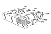
供給管(図示せず)がインク貯蔵器24(図1)からプリントヘッド20によって画定されるインクチャネル128aおよび128b(図2)にインクを導入する。インクチャネルはその中を移動するインクが各発射チャンバ132(図2)と連結するように構成される。
【0018】
各発射チャンバ132は対応する薄膜抵抗器を有する。かかる抵抗器は外部のマイクロプロセッサおよび対応するドライバによって印加される電流によって選択的に駆動(加熱)される。各抵抗器への導電性駆動線はペン本体12(図1)の外部に取り付けられた回路26に設けられている。抵抗器駆動線の端部の回路接触パッド18(拡大して示す)はキャリッジ(図示せず)に取り付けられた整合回路上に設けた同様のパッドと係合する。
【0019】
弁部材110がインクジェットペン10(図1および図2)のプリントヘッド20内に取り付けられる。より詳細には、弁部材110はプリントヘッドのインクチャネル128aおよび128bに接続あるいは一体化される。この弁部材はインク供給源と発射チャンバ132との間に配置される。
【0020】
インクチャネル128aおよび128bはそれぞれ弁装置の上流側および下流側のインクチャネルを画定する。これらのインクチャネルはインク供給源から発射チャンバに流れるインクの連続的な通路からなる。より詳細には、ペンのインク貯蔵器24内、あるいはペン10から離れた場所にあるインク供給源がこのインクチャネル128aと連結する。
【0021】
本発明の好適な一実施例では、弁部材110は次に説明するようにインクチャネル内の開位置あるいは閉位置に移動可能で弾性変形可能な材料から作られる。
【0022】
弁部材110は1つの固定された端部114においてチャネル128bの下側表面116に接続されている。弁部材110の自由端部118はチャネル128bの下側表面116、あるいは同チャネルの対向する上側表面119に向かう方向に移動可能である。
【0023】
弁部材110が変形した位置にあるとき、自由端部118は上側表面119に接触しており、この弁部材は閉位置(図2に実線で示す)にある。弁部材が閉位置にあるとき、インクチャネル128bから発射チャンバ132へのインクの流れは大幅に低減される。弁部材110が非変形位置すなわち緩和位置にあるとき、自由端部118は下側表面116に向かって移動し、開位置(図2に破線で示す)に入る。弁110が開位置にあるとき、インクはインクチャネル128bから発射チャンバ132に流れる。
【0024】
発射チャンバ132と弁部材110との間のインクチャネル128b内のインク圧があらかじめ選択されたレベルより高くなると、この液圧に押されて弁部材110は閉位置に入る。すなわち、弁部材の自由端部118が湾曲して上側表面119に接触し、それによって発射チャンバ132(図2)へのインクの流れを大幅に低減する。
【0025】
発射チャンバ132と弁部材110との間のインク流路内のインク圧があらかじめ選択されたレベルより低くなると、弁部材110は開位置に戻る。その結果、弁部材110の自由端部118は下側表面116に向かって戻り、それによってインク供給源から発射チャンバ132へのインクの流れが可能になる。弁部材110は、この弁部材が通常は閉位置にあり、開位置に向かって変形可能であるように製造することも可能であることに注目されたい。
【0026】
好適には、インク発射チャンバ132の両側にそれに隣接して2つの弁部材110が配置される。発射チャンバ132の両側に配置された2つの弁部材110によって、発射チャンバは弁部材110が変形して閉位置に入るときインクチャネル128bから隔離される。しかし、チャンバがインクチャネルとの間に単一の接続部を有する設計においては、単一の弁部材を使用することができると考えられる。
【0027】
発射処理中にインク発射チャンバを隔離することによって抵抗器の通電時のインクの逆流が低減され、それによってプリントヘッド内の液体の流れおよび圧力の調整がさらに改善される。好適には、各発射チャンバ132には少なくとも1つの弁部材110と接続する。
【0028】
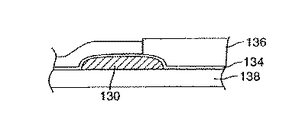
弁部材110は従来の薄膜積層技術(図4a〜図4cに示す)を用いて製造することができる。製造出発材料はメッキされた金属基板あるいはポリマー基板138より構成することができる(図4a)。メッキされた金属基板は、ニッケルからなるものが好適であり、ポリマー基板としてはポリイミドからなるものが好適である。
【0029】
比較的厚い犠牲 (sacrificial)フォトレジスト層130のパターンが、好適には厚さが約20μm、(図4cに示す弁部材110の断面に直角に測定した)幅が25μm、長さ(図4a)が40μmである基板138上に設けられる。犠牲層130の寸法は弁部材110の所望の寸法によって決まる。犠牲層130は後に除去され、弁部材110が基板138から離れて自由に動くようにする。基板の露出された面はインクチャネル128の下側表面116になる(図2)。
【0030】
薄い導体層134が基板138および犠牲層130の上に均一に塗布される(図4a)。導体層134は好適には従来のスパッタリング技術で被着されたチタンおよび金あるいは同じくスパッタリングによって被着されたクロムおよび銅で構成される。チタン(あるいはクロム)は接着剤として機能し、金(あるいは銅)はメッキ処理中に導電体として機能する。層134の厚さは好適には約1000Åである。
【0031】
導体層134の上に第2の犠牲フォトレジスト層136が塗布され、弁部材110の長さ、幅および高さを画定するようにパターニングされる(図4b)。次に、好適にはニッケルからなる弁部材110が導体層134の露出部分を覆うようにメッキされる。弁部材110の被着に続いて、フォトレジスト層136および層134の露出部分が除去される(図4c)。次に、フォトレジスト層130が除去され、これによって弁部材110の一端が自由に動くことができる。
【0032】
インクチャネルは弁部材110と同時に製造することができ、またインクチャネルに適合する表面上に別途製造してもよい。
【0033】
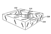
図2に示す弁部材110の製造はレーザー切削技術(laser ablation techniques)を用いて行なうこともできる(図8)。好適なレーザー切削製造処理によれば、適当な基板138がレーザー処理チャンバに搬送され、弁部材110と発射チャンバ132が1つあるいはそれ以上のマスクおよびレーザー放射線を用いてレーザ切削される。レーザー放射線は、F2、ArF、KrCl、KrFあるいはXeCl型のエキシマーレーザーによって生成することができる。この処理を行なうためのレーザーシステムは一般にビーム供給光学システム、位置合わせ光学システム、高精度、高速マスクシャトルシステム、および基板138の取り扱いと位置決めを行なう機構を含むプロセスチャンバを含む。
【0034】
より詳細には、弁部材110は好適にはポリイミドあるいは他の適当なポリマー材料からなる基板138をレーザー処理チャンバ内にレーザービームに対して比較的大きな半角(half-angle)を形成して位置決めすることによって製造することができる。この半角は使用されるレーザーのエネルギーレベルによって決まる。たとえば、800 mJ/cm2のXeClレーザーを用いる場合、半角は好適には約6である。好適な半角はレーザーエネルギー源の減少とともに増大する。弁部材はくさび111の幅の広い方の端部がインクチャネル128の下側表面116と一体となるようなほぼくさび状を成すように切削される(図8)。
【0035】
レーザー切削によって弁部材110が画定された後、インクチャネル128が完全に画定される。基板がレーザービームに対してほぼ90゜の角度を成して配置され、次にインクチャネル128が厚さ約25μm、幅約25μm、長さ約40μmになるように切削される。弁部材110は上側方向(すなわち、インクチャネル128の上側表面に向かう方向)あるいは下側方向(すなわち、インクチャネル128の下側表面116に向かう方向)に変形可能である。
【0036】
レーザー切削処理の最後のステップは洗浄ステップであり、基板138のレーザー切削された部分が洗浄ステーション(図示せず)の下に配置される。洗浄ステーションでは、レーザー切削によって生じた切り屑が当該技術分野における標準的な方法で除去される。
【0037】
弁部材およびインクジェットチャネルの形成のためのレーザー切削処理には従来のリソグラフィック電鋳処理に比べて多くの利点がある。たとえば、レーザー切削処理は一般的に従来のリソグラフィック電鋳処理に比べ、低コストでしかも簡単である。さらに、レーザー切削を用いることによって、弁部材およびチャネルを従来の電鋳処理では実際上得られなかった形状とすることができる。
【0038】
本実施例ではエキシマーレーザーを用いるが、ほぼ同じ波長およびエネルギー密度を有する他の紫外線光源を用いてこの切削処理を実行することも可能である。かかる紫外線光源の波長は150nmから400nmの範囲内とし、被切削基板内での吸収を大きくすることが好適である。さらに、切削された材料をその周囲に残った材料を基本的に加熱することなく、高速に噴射するためには、エネルギー密度を約100ミリジュール/平方センチメートルより高く、パルス長を約1マイクロ秒より短くしなければならない。
【0039】
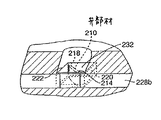
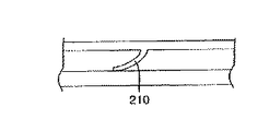
本発明の他の好適な実施例では、弁部材210が発射チャンバ232の側壁に一体に接続される(図3)。好適には、弁部材210はその一端(固定端部)214において発射チャンバの壁220に取り付けられる。この弁部材の第2の端部すなわち自由端部218は発射チャンバ232の内部に向かう方向すなわちインクチャネル228bに向かう方向に変形可能となる。
【0040】
弁部材210は、常開位置(図3の破線で示す)あるいは常閉位置(図3の実線で示す)に製造することができる。発射チャンバ232内のインク圧が発射チャンバに隣接するインクチャネル228b内の液体インク圧以下であるとき、弁部材210は開位置にあり、インクはインク流路から発射チャンバに流れる。発射チャンバ232内の液圧があらかじめ選択されたレベルを越えて増加すると、弁部材210が屈曲して閉位置に入り、弁部材の自由端部218はインクチャネル228bに向かって移動し、これによって発射チャンバからインク流路へのインクの流れはほぼ阻止される。
【0041】
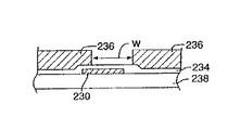
図3に示す弁部材210の実施例は薄膜積層技術(図5a〜図5dに示す)を用いて製造することができる。図5aおよび図5cは弁部材210の好適実施例の側面図であり、図5bおよび図5dはそれに対応するこの弁部材の平面図である。弁部材210はメッキされた金属基板あるいはポリマー基板238の上部をメッキすることによって製造することができる(図5a)。適切なメッキ金属基板としてはニッケルからなるものが好適であり、適切なポリマー基板としてはポリイミドからなるものが好適である。
【0042】
基板238上に薄い犠牲フォトレジスト層230が約1μmの厚さにで塗布され、これをパターニングして弁部材210の長さが画定される(図5a)。犠牲層230は後に除去され、弁部材210は基板238から離れて自由に動く。
【0043】
基板238の露出部分および犠牲層230の上に薄い導体層234が均一に塗布される(図5a)。導体層234としては、上述した実施例において導体層134に関連して説明したものと同じ寸法を有し、同じ材料からなるものが好ましい。導体層134の弁部材210にならない部分はフォトレジスト層236を用いてパターニングされ、適当なエッチング剤(etchant)を用いて除去される(図5a)。
【0044】
犠牲フォトレジスト層236は弁部材210の高さと幅を画定する(図5aおよび図5c)。犠牲層236の厚さは好適には弁部材210の所望の高さより約5μm厚い。次に、弁部材210が被着され、好適には、従来のメッキ技術によって被着されたニッケルからなる(図5cおよび図5d)。次に、フォトレジスト層230および236が除去され、これによって弁部材210は左右方向に湾曲することができる(図5cおよび図5d)。
【0045】
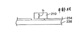
レーザー切削技術を用いて図3に示す弁部材210の実施例を製造することも可能である。好適な処理においては、適当な基板238がレーザー処理チャンバーに搬送され、1あるいはそれ以上のマスクとレーザー放射線を用いて弁部材210と発射チャンバ232がレーザー切削される(図9)。レーザー放射線はF2、ArF、KrCl、KrFあるいはXeCl型のエキシマーレーザーによって生成することができる。この処理を行なうためのレーザーシステムは一般にビーム供給光学システム、位置合わせ光学システム、高精度、高速マスクシャトルシステム、および基板238の取り扱いと位置決めを行なう機構を含むプロセスチャンバを含む。
【0046】
より詳細には、基板がレーザービームに対して垂直に配置された状態で、弁部材210がレーザー放射線を用いてレーザーマスクを介して画定される。また、それに隣接するインクチャネルも他のマスクを用いて同じ切削処理中に画定されるか弁のパターンを含む共通のマスク上にチャネルのパターンをそれに並べて配置することができる。弁およびチャネルのパターンは、レーザービーム内に順次移動させることができる。かかるマスクに用いるマスキング材料としては、好適にはたとえば多層誘電体あるいはアルミニウム等の金属からなる選択されたレーザー波長において高い反射性を有するものが好適である。次に、基板238が反転され、基板の裏側がレーザー切削され弁部材210がインクチャネル228から切り離される。
【0047】
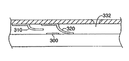
本発明の他の実施例では2あるいはそれ以上の弁部材がたとえば抵抗器あるいは圧電変換器等のアクチュエータ源と組み合わせられる(図6aおよび図6b)。このような組み合わせでは、弁部材をプリントヘッドのインクチャネル328b内に構成して、あらかじめ選択された量のインク等の液体をこのチャネルを介して吸入吐出することができる。
【0048】
より詳細には、抵抗器300あるいは他のアクチュエータが2つの弁部材310、320の間に配設される。これらの弁部材はこれらが通常開位置に向かって変形可能である非変形の閉位置に位置するように製造される。すなわち、この弁部材の自由端部311は通常インクチャネル328aの下側表面316に接触しており、その結果、インクチャネル中のインクの流れが大幅に低減される。2つの弁部材310および320の間のチャネル328aにはあらかじめ選択された量のインクが蓄えられる。
【0049】
インクの吸入吐出動作は、2つのステップからなる。まず、抵抗器300が加熱されるとインク気泡330が形成される。インク気泡330が膨脹するにつれて下流側の弁部材320が膨脹する気泡によって生じる液圧のために開位置に屈曲する。開位置では、弁310と弁320の間に蓄えられたインクが弁部材320を通過してインクチャンバ332に向かって流れる(図6a)。
【0050】
インク気泡330の膨脹によって弁部材320が開き、インクが下流側に(すなわちインクチャンバ332に向かって)流れると、2つの弁部材310および320の間のインクチャネル内の液圧が低下する。この圧力降下によって勾配が生じ、上流側の弁部材310が開位置に湾曲し、下流側の弁部材320が閉じる(図6b)。上流側弁部材310が開くと、2つの弁部材の間に画成されたインク流路の容積がインクによって再充填される。このインクは抵抗器300が再度起動されるまで弁部材310および320の間のインク流路328bに蓄えられる。
【0051】
吸入吐出されるインクの量は、抵抗器300のエネルギレベルとインクチャネル328bの形状によって決まる。たとえば、25μmの抵抗器、幅25μm、高さ25μm、長さ50μmのインク流路の場合には、約20 plのインク吸入排出量が得られる。
【0052】
本発明の他の実施例では、3あるいはそれ以上の弁部材410、420、430を用いてインクジェットプリントヘッド20内の液体の流れを制御しながら、同時にグレースケールプリント能力を向上させる(図7)。
【0053】
グレースケールプリント能力の向上によってより鮮明ではっきりとしたイメージが生成される。本発明の好適な一実施例では、インク滴中のインク染料装填量を変更することによって、インクジェットプリントヘッド内の液体の流れの制御によってプリントグレースケールを変化させることを可能とする。
【0054】
特に、2つのインクチャネル428cおよび428dは1つのインク発射チャンバ432と連結している。第1のインクチャネル428cは、低染料装填インク供給源とも連結しており、第2のインクチャネル428dは高染料装填インク供給源とも連結している。
【0055】
弁部材410、420および430は、第1のインクチャネル428cおよび第2のインクチャネル428d内に配置される。弁部材410、420および430は、非変形状態では閉位置をとるように製造される。すなわち、各弁部材410 、 420 および 430におけるインクの流れは弁部材410 、 420 および 430が変形するまでまたは開位置をとるまで、ほぼ遮断される。第2の高染料装填インクチャネル428d内には少なくとも2つの弁部材420、430が配置され、その間に抵抗器等の加熱素子440が配置されている。発射チャンバ内のインクの濃度は第2のインクチャネル428dからの高染料装填インクを選択的に吸入吐出することによって(すなわち、抵抗器440に通電することによって)変更される。第1のインクチャネル428cを流れる低染料装填インクが発射チャンバ432に入ると、ある量の高染料装填インクが第2のインクチャネル428dから発射チャンバに吸入される。吸入される高染料装填インクの量と吸入吐出機構のはたらきは上述した実施例において説明したものと同様である。高染料装填インクと低染料装填インクが発射チャンバ内で混合し、その混合物がノズル422から噴射される。
【0056】
以上、本発明の原理を好適な実施例を参照しながら図示および説明したが、本発明の構成およびその細部にはかかる原理から逸脱することなくさらに変更を加えることができることは明らかである。たとえば、弁部材は単独で使用することが可能であり、あるいはさまざまな数の弁部材の組み合わせをインクジェットプリントヘット内のさまざまな位置で使用して本発明の各代替実施例を参照して上述したものと同様の結果を得ることも可能である。
【0057】
以上、本発明の実施例について詳述したが、以下、本発明の各実施態様の例を示す。
(実施態様1)
インクジェットプリントヘッド内のインク圧を調整するシステムであって、流体通路(128a、128b)を含むプリントヘッド(20)と、前記流体通路はある量のインクを蓄えるための容積を画定し、前記流体通路はさらに前記プリントヘッドからインク滴を噴射するノズル(22)を有する発射チャンバ(132)と連結するものであり、前記プリントヘッドに取り付けられ、前記流体通路内に配置された第1の可撓性弁部材(110)とを含み、前記弁部材は、前記流体通路内の圧力勾配に応じて、インクが前記流体通路を流れる開位置および前記流体通路中のインクの流れが制限される閉位置まで変形することを特徴とするインク圧調整システム。
(実施態様2)
前項1に記載のシステムであって、前記第1の弁部材はさらに前記流体通路(128a、128b)に設置され、前記流体通路内の圧力勾配に応じて、前記流体通路内のインクの流れを制限する位置までおよびその位置から離れるように湾曲する弾性的可撓性を有するフラップ(110)からなることを特徴とするインク圧調整システム。
(実施態様3)
前項2に記載のシステムであって、前記フラップ(110)の第1の端部(114)は前記の流体通路(128a、128b)の表面(116、119)に一体に接続されていることを特徴とするインク圧調整システム。
(実施態様4)
前項1に記載のシステムはさらに第2の可撓性弁部材を含み、前記第2の可撓性弁部材は、前記流体通路(128a、128b)に設置され、前記流体通路内の圧力勾配に応答して前記流体通路内のインクの流れを制限する位置までおよびその位置から離れるように湾曲する弾性的可撓性を有するフラップ(110)からなることを特徴とするインク圧調整システム。
(実施態様5)
前項2に記載のシステムであって、前記の弁部材(110)は発射チャンバ(132)内に配置され、前記の弁部材は前記プリントヘッド(20)からインク滴が噴射されるとき前記流体通路(128a、128b)内のインクの流れがほぼ遮断される位置まで湾曲することを特徴とするインク圧調整システム。
(実施態様6)
前項1に記載のシステムであって、前記の第1の弁部材(110)は微細加工処理によって製造されることを特徴とするインク圧調整システム。
(実施態様7)
前項1に記載のシステムであって、前記の第1の弁部材(110)はレーザー切削処理によって製造されることを特徴とするインク圧調整システム。
(実施態様8)
インクジェットプリントヘッド内の液圧を制御するシステムであって、第1のインクチャネル(428d)を画定するベースを有するプリントヘッド(20)と、前記第1のインクチャネルの一部が高染料装填インクを蓄えるための容積を画定し、前記第1のインクチャネルはさらに前記プリントヘッドからインク滴が噴射される発射チャンバ(432)と連結するものであり、前記プリントヘッドの前記ベース内に画定された第2のインクチャネル(428c)と、前記第2のインクチャネルの一部が低染料装填インクを蓄えるための容積を画定し、前記第2のインクチャネルは前記発射チャンバと連結している第2のインクチャネル(428c)と、その間にインクを蓄えるための容積を画定する前記第1のインクチャネル内に取り付けられた少なくとも2つの弾性的可撓性を有するフラップ(420、430)と、前記第1のフラップ(420)は前記第2のフラップ(430)から間隔をおいて配置されるものであり、前記第2のインクチャネル(428c)内に取り付けられた少なくとも1つの弾性的可撓性を有するフラップ(410)と、前記の第1のインクチャネル内の前記2つのフラップの間に配置された加熱素子(440)とからなり、前記加熱素子が稼動されると前記フラップの間のある量のインクを加熱し、前記第1のフラップを閉位置まで変形させ、前記第2のフラップを開位置まで変形させることによって、前記のインク量を前記第2のフラップを通過して移動させることを特徴とするインク圧調整システム。
(実施態様9)
インクジェットプリントヘッド内の液圧を制御する方法であって、流体通路(128a、128b)を含むプリントヘッド(20)を設け、前記プリントヘッドは、前記流体通路はある量のインクを蓄えるための容積を画定し、前記流体通路は前記プリントヘッドからインク滴を噴射するノズル(22)を有する発射チャンバ(132)と連結するものであり、
前記流体通路内の前記プリントヘッドに第1の可撓性弁部材(110)を取り付け、
前記通路内の圧力の変化に応じて、前記第1の可撓性弁部材を前記流体通路内をインクが流れる開位置と前記流体通路内のインクの流れが制限される閉位置に移動させることを特徴とするインク圧調整方法。
(実施態様10)
前項9に記載の方法はさらに前記流体通路(128a、128b)内の前記プリントヘッド(20)に第2の弁部材(110)を取り付け、前記通路内の圧力の変化に応じて、前記第2の可撓性弁部材(110)を前記流体通路内をインクが流れる開位置と前記流体通路内のインクの流れが制限される閉位置に移動させるステップを含むことを特徴とするインク圧調整方法。
【0058】
【発明の効果】
以上説明したように、本発明では、インクジェットプリントヘッド内のインクの圧力を調整する手段によって、噴射後のインクの逆流を防ぎ、インクの充填を効率よくおこなうことによって均一なインク滴を連続的に噴射することができる。
【図面の簡単な説明】
【図1】本発明の一実施例を備えるインクジェットプリンタペンの斜視図。
【図2】本発明の一実施例の拡大部分断面図。
【図3】本発明の他の実施例の拡大部分断面図。
【図4a】図2の実施例の製造工程を表す図。
【図4b】図2の実施例の製造工程を表す図。
【図4c】図2の実施例の製造工程を表す図。
【図5a】図3の実施例の製造工程を表す図。
【図5b】図2の実施例の製造工程を表す図。
【図5c】図2の実施例の製造工程を表す図。
【図5d】図2の実施例の製造工程を表す図。
【図6a】本発明の他の実施例の拡大部分断面図。
【図6b】本発明の他の実施例の拡大部分断面図。
【図7】本発明の他の実施例の拡大部分断面図。
【図8】本発明の一実施例のレーザー切削を用いた製造を示す拡大斜視図。
【図9】弁装置の一実施例のレーザー切削を用いた製造を示す拡大斜視図。
【符号の説明】
10:インクジェットプリンタペン
12:ペン本体
18:回路接触パッド
20:プリントヘッド
22:ノズル
24:インク貯蔵器
110:弁部材
128、128a、128b:インクチャネル
130:犠牲フォトレジスト層
132:発射チャンバ
134:導体層
136:第2の犠牲フォトレジスト層
138:基板
210:弁部材
228、228b:インクチャネル
230:犠牲フォトレジスト層
232:発射チャンバ
234:導体層
236:フォトレジスト層
238:基板
300:抵抗器
310、320:弁部材
328a、328b:インクチャネル
330:インク気泡
332:インクチャンバ
410、420、430:弁部材
422:ノズル
428c、428d:インクチャネル
432:インク発射チャンバ
440:加熱素子[0001]
BACKGROUND OF THE INVENTION
The present invention controls fluid flow and pressure in an inkjet printheadInk pressure adjustment system and method for controlling fluid pressure in an inkjet printheadAbout.
[0002]
[Prior art]
Inkjet printers include pens that form small ink drops and eject them toward a print medium. This pen is attached to a reciprocating carriage in the printer. Such pens include a printhead having an orifice plate with very small nozzles from which ink drops are ejected. An ink chamber is provided adjacent to the nozzle for storing ink prior to ejection. Ink is supplied to the ink chamber via an ink channel connected to an ink supply. The ink supply is stored, for example, in the ink reservoir of the pen or supplied to the pen from a remote location.
[0003]
Ink droplet ejection from the nozzle is accomplished by rapidly heating a quantity of ink in the adjacent ink chamber. By this thermal process, the ink in the ink chamber is heated and bubbles are formed. The formation of thermal ink jet bubbles is known as “nucleation”. Ink drops are pushed out of the orifice by the rapid expansion of the ink vapor. This process is called “firing”. The ink in the chamber can be heated, for example, by a resistor that is responsive to a control signal. This resistor is provided adjacent to the nozzle.
[0004]
Inkjet printheads typically rely on capillary forces that draw ink from an ink channel into an ink chamber. Here, the term “back pressure” means partial vacuum in the print head. Back pressure is considered in the positive direction, so increasing back pressure represents an increase in partial vacuum. Capillary forces overcome the slight positive back pressure generated by the regulator. When ink is ejected from the chamber, the chamber is replenished by capillary action and the system is ready to eject the next drop of ink.
[0005]
When the filled ink flows into the empty chamber, a part of the ink protrudes outside the orifice due to the inertia of the moving ink. Since the ink in the pen is generally kept at a slightly positive back pressure, the protruding portion of the ink immediately returns to the ink chamber. This reciprocating motion decreases after being repeated several times, and finally stops, that is, attenuates.
[0006]
[Problems to be solved by the invention]
When an ink droplet is ejected when the ink rises from the orifice, the ejected ink droplet forms a dumbbell shape, and its moving speed is low. On the contrary, when ink is ejected when the ink moves backward from the nozzle, the ejected ink droplet has a bowl shape, and its moving speed becomes inappropriately high. Ink motion within the chamber is attenuated between these two extremes, producing well-shaped ink drops and optimal print quality.
[0007]
The print speed (i.e., ink drop ejection speed) must be slow so that the ink motion in the chamber can decay during ink drop firing. A period necessary for the ink motion to be sufficiently attenuated is called an attenuation period.
[0008]
In order to reduce the decrease in printing speed due to the decay period, the shape of the ink chamber has been devised. The ink chamber is compressed to reduce the filling rate of the ink chamber to rapidly damp the refilling ink that has risen. In general, the length and area of the chamber is configured to reduce the reciprocating motion of the chamber filled ink (and thus reduce the decay period). However, the decay period could not be eliminated from the print head. Therefore, the print speed must be adapted to the decay period, otherwise problems will occur with the print and image.
[0009]
Another problem with ink jet print heads is that ink “blowback” tends to occur when ink drops are ejected. Backflow occurs when a portion of the ink in the chamber is pushed back to the adjacent channel portion upon firing. Backflow is always caused by the chamber being always connected to the channel and, therefore, most of the ink in the chamber is not ejected from the printhead upon firing, but rather flows back into the channel.
[0010]
Backflow wastes some of the energy ("turn-on energy" or TOE) that should be used to eject ink drops from the chamber. This is because only a part of the total amount of ink in the chamber is actually ejected. Therefore, if the backflow is reduced, the TOE is reduced and the thermal efficiency of the inkjet pen is improved. In addition, high TOE results in excessive heating of the print head. When the print head is heated excessively, bubbles are generated from the air dissolved in the ink, and prenucleation of the ink bubbles occurs. Bubbles and precursor nucleation reduce print quality.
[0011]
[Means for Solving the Problems]
The present invention provides a system for controlling fluid flow and hydraulic pressure within an inkjet printhead. In one embodiment of the present invention, liquid flow and pressure within the print head is controlled by a passive valve device attached to or integral with the print head of the inkjet pen.
[0012]
In one embodiment of the invention, the valve device includes at least one small passive valve member. The valve member comprises an elastically deformable flap disposed in the ink channel adjacent to the firing chamber. The flap is flexible so as to enter and exit a position that regulates the flow and pressure of ink entering and exiting the ink firing chamber.
[0013]
The valve member is deformable to a position that substantially isolates the ink chamber from the channel during ink drop firing. By isolating the ink chamber in this manner, ink backflow is reduced. During ejection, ink in the chamber is blocked by the deformed valve member and cannot return to the ink channel, but only out of the nozzle. By reducing the back flow of ink, the adjustment of the fluid pressure in the pen is improved and the TOE is reduced.
[0014]
Furthermore, by using such deforming valve members, the ink chamber is immediately isolated after filling, thereby shortening the ink decay period. That is, by isolating the ink chamber, the retreat distance of the rising ink from the nozzle is limited, and the reciprocation of the ink is reduced.
[0015]
The present invention can realize microfabrication and low cost, and can use batch processing using a wafer and obtain repeatability.
[0016]
【Example】
In FIG. 1, the valve device of the present invention is built in an ink jet printer pen 10. The pen includes a pen body 12 that defines an ink reservoir 24. Ink reservoir 24 is configured to hold a quantity of ink. The print head 20 is fitted into the bottom 14 of the pen body 12, and the ejection of ink droplets from the ink reservoir 24 is controlled. The print head 20 defines a group of nozzles 22 for firing ink in a controlled pattern during printing. Each nozzle 22 is connected to a firing chamber defined in the base of the printhead 20.
[0017]
A supply tube (not shown) introduces ink from the ink reservoir 24 (FIG. 1) into the ink channels 128a and 128b (FIG. 2) defined by the printhead 20. The ink channel is configured such that ink traveling therein is coupled to each firing chamber 132 (FIG. 2).
[0018]
Each firing
[0019]
A
[0020]
Ink channels 128a and 128b define ink channels upstream and downstream of the valve device, respectively. These ink channels consist of a continuous path of ink flowing from the ink supply to the firing chamber. More particularly, an ink supply in the pen ink reservoir 24 or at a location remote from the pen 10 is coupled to the ink channel 128a.
[0021]
In one preferred embodiment of the present invention, the
[0022]
The
[0023]
When the
[0024]
When the ink pressure in the ink channel 128b between the firing
[0025]
When the ink pressure in the ink flow path between firing
[0026]
Preferably, two
[0027]
By isolating the ink firing chamber during the firing process, ink backflow when the resistor is energized is reduced, thereby further improving liquid flow and pressure regulation within the printhead. Preferably, each firing
[0028]
The
[0029]
The pattern of the relatively thick
[0030]
A
[0031]
A second
[0032]
The ink channel can be manufactured at the same time as the
[0033]
The
[0034]
More particularly, the
[0035]
After the
[0036]
The last step of the laser cutting process is a cleaning step, where the laser cut portion of the
[0037]
Laser cutting processes for the formation of valve members and inkjet channels have many advantages over conventional lithographic electroforming processes. For example, laser cutting processes are generally cheaper and simpler than conventional lithographic electroforming processes. Further, by using laser cutting, the valve member and the channel can be formed into a shape that was not practically obtained by the conventional electroforming process.
[0038]
In this embodiment, an excimer laser is used, but it is also possible to perform this cutting process using other ultraviolet light sources having substantially the same wavelength and energy density. The wavelength of such an ultraviolet light source is preferably in the range of 150 nm to 400 nm, and it is preferable to increase the absorption in the substrate to be cut. Furthermore, in order to inject the cut material at high speed without essentially heating the material remaining around it, the energy density is higher than about 100 millijoules / square centimeter and the pulse length is longer than about 1 microsecond. Must be shortened.
[0039]
In another preferred embodiment of the present invention,
[0040]
The
[0041]
The embodiment of the
[0042]
A thin
[0043]
A
[0044]
The
[0045]
It is also possible to manufacture the embodiment of the
[0046]
More specifically, the
[0047]
In another embodiment of the invention, two or more valve members are combined with an actuator source such as a resistor or a piezoelectric transducer (FIGS. 6a and 6b). In such a combination, the valve member can be configured in the
[0048]
More specifically, a
[0049]
The ink suction and discharge operation includes two steps. First, when the
[0050]
The expansion of the
[0051]
The amount of ink that is sucked out is determined by the energy level of the
[0052]
In another embodiment of the present invention, three or
[0053]
Improved grayscale printing capabilities produce a clearer and clearer image. In one preferred embodiment of the present invention, the print gray scale can be changed by controlling the flow of liquid in the ink jet print head by changing the ink dye loading in the ink drop.
[0054]
In particular, the two
[0055]
The
[0056]
While the principles of the invention have been illustrated and described with reference to a preferred embodiment, it will be apparent that further modifications can be made to the structure and details of the invention without departing from such principles. For example, the valve member can be used alone, or a combination of various numbers of valve members can be used at various locations within the inkjet print head as described above with reference to each alternative embodiment of the present invention. It is also possible to obtain results similar to those.
[0057]
As mentioned above, although the Example of this invention was explained in full detail, the example of each embodiment of this invention is shown below.
(Embodiment 1)
A system for regulating ink pressure in an inkjet printhead, comprising a printhead (20) comprising fluid passages (128a, 128b), said fluid passage defining a volume for storing a quantity of ink, said fluid The passage is further coupled to a firing chamber (132) having a nozzle (22) for ejecting ink droplets from the print head, and is attached to the print head and disposed within the fluid passage. The valve member includes an open position in which ink flows through the fluid passage and a closed position in which the flow of ink in the fluid passage is restricted in accordance with a pressure gradient in the fluid passage. An ink pressure adjustment system characterized by being deformed to a minimum.
(Embodiment 2)
2. The system according to claim 1, wherein the first valve member is further installed in the fluid passage (128a, 128b), and the flow of ink in the fluid passage is controlled according to a pressure gradient in the fluid passage. An ink pressure adjustment system comprising an elastic flexible flap (110) that curves to and from a restricting position.
(Embodiment 3)
The system according to claim 2, wherein the first end (114) of the flap (110) is integrally connected to the surface (116, 119) of the fluid passage (128a, 128b). A characteristic ink pressure adjustment system.
(Embodiment 4)
The system according to the preceding item 1 further includes a second flexible valve member, and the second flexible valve member is installed in the fluid passage (128a, 128b), and the pressure gradient in the fluid passage is adjusted. An ink pressure adjustment system comprising an elastic flexible flap (110) that curves in response to and away from a position that restricts the flow of ink in the fluid passage.
(Embodiment 5)
3. The system of claim 2, wherein the valve member (110) is disposed in a firing chamber (132), and the valve member is configured to pass the fluid passage when ink drops are ejected from the print head (20). (128a, 128b) An ink pressure adjusting system, which is curved to a position where the ink flow is substantially blocked.
(Embodiment 6)
2. The ink pressure adjusting system according to claim 1, wherein the first valve member (110) is manufactured by microfabrication processing. 3.
(Embodiment 7)
2. The ink pressure adjusting system according to claim 1, wherein the first valve member (110) is manufactured by a laser cutting process.
(Embodiment 8)
A system for controlling hydraulic pressure in an inkjet printhead, the printhead (20) having a base defining a first ink channel (428d) and a portion of the first ink channel comprising high dye loaded ink The first ink channel is further coupled to a firing chamber (432) through which ink drops are ejected from the print head, and is defined within the base of the print head A second ink channel (428c) and a portion of the second ink channel define a volume for storing low dye-loaded ink, and the second ink channel is coupled to the firing chamber. At least two of the ink channels (428c) mounted in the first ink channel defining a volume for storing ink therebetween A sexually flexible flap (420, 430) and the first flap (420) are spaced from the second flap (430), and the second ink channel (428c) from at least one elastic flexible flap (410) and a heating element (440) positioned between the two flaps in the first ink channel. And when the heating element is activated, heating a certain amount of ink between the flaps, deforming the first flap to a closed position, and deforming the second flap to an open position, The ink pressure adjustment system is characterized in that the ink amount is moved through the second flap.
(Embodiment 9)
A method for controlling hydraulic pressure in an inkjet printhead, comprising a printhead (20) including fluid passages (128a, 128b), the printhead having a volume for storing a quantity of ink. The fluid passage is coupled to a firing chamber (132) having a nozzle (22) for ejecting ink drops from the print head;
Attaching a first flexible valve member (110) to the print head in the fluid passage;
In response to a change in pressure in the passage, the first flexible valve member is moved to an open position where ink flows in the fluid passage and a closed position where ink flow in the fluid passage is restricted. An ink pressure adjusting method characterized by the above.
(Embodiment 10)
The method according to item 9 further includes attaching a second valve member (110) to the print head (20) in the fluid passage (128a, 128b), and changing the second valve member in response to a change in pressure in the passage. And moving the flexible valve member (110) to an open position where the ink flows in the fluid passage and a closed position where the ink flow in the fluid passage is restricted. .
[0058]
【The invention's effect】
As described above, according to the present invention, the means for adjusting the pressure of the ink in the ink jet print head prevents the back flow of the ink after ejection and efficiently fills the ink by continuously filling the ink. Can be injected.
[Brief description of the drawings]
FIG. 1 is a perspective view of an ink jet printer pen including an embodiment of the present invention.
FIG. 2 is an enlarged partial cross-sectional view of an embodiment of the present invention.
FIG. 3 is an enlarged partial cross-sectional view of another embodiment of the present invention.
4A is a diagram showing a manufacturing process of the embodiment of FIG. 2; FIG.
4b is a diagram showing a manufacturing process of the embodiment of FIG.
4c is a diagram showing a manufacturing process of the embodiment of FIG.
5A is a diagram showing a manufacturing process of the embodiment of FIG. 3. FIG.
5b is a diagram showing a manufacturing process of the embodiment of FIG.
FIG. 5c is a diagram showing a manufacturing process of the embodiment of FIG.
FIG. 5d is a diagram showing a manufacturing process of the embodiment of FIG.
FIG. 6a is an enlarged partial cross-sectional view of another embodiment of the present invention.
FIG. 6b is an enlarged partial cross-sectional view of another embodiment of the present invention.
FIG. 7 is an enlarged partial sectional view of another embodiment of the present invention.
FIG. 8 is an enlarged perspective view showing manufacture using laser cutting according to an embodiment of the present invention.
FIG. 9 is an enlarged perspective view showing manufacture using laser cutting of an embodiment of the valve device.
[Explanation of symbols]
10: Inkjet printer pen
12: Pen body
18: Circuit contact pad
20: Print head
22: Nozzle
24: Ink reservoir
110: Valve member
128, 128a, 128b: ink channel
130: Sacrificial photoresist layer
132: Launch chamber
134: Conductor layer
136: Second sacrificial photoresist layer
138: Board
210: Valve member
228, 228b: Ink channel
230: Sacrificial photoresist layer
232: Launch chamber
234: Conductor layer
236: Photoresist layer
238: Board
300: Resistor
310, 320: Valve member
328a, 328b: Ink channel
330: Ink bubbles
332: Ink chamber
410, 420, 430: Valve members
422: Nozzle
428c, 428d: Ink channel
432: Ink firing chamber
440: Heating element
Claims (5)
第1のインクチャネルを画定するベースを有するプリントヘッドであって、前記第1のインクチャネルの一部がインクを蓄えるための容積を画定し、前記第1のインクチャネルは、インク滴が該プリントヘッドから噴射される発射チャンバと流体連通しているプリントヘッドと、
前記チャンバからインク滴を噴射するために、前記チャンバ内の前記インクを加熱するために発射チャンバ内に配置されたヒーターと、
その間にインクを蓄えるための容積を画定する前記第1のインクチャネル内に取付けられている少なくとも2つの可撓性フラップであって、該2つのフラップの第1のフラップが該2つのフラップの第2のフラップから間隔をあけられている2つの可撓性フラップと、
起動されると前記フラップ間のある量のインクを加熱し、前記第1のフラップを閉位置まで変形させ、前記第2のフラップを開位置まで変形させることによって、前記ある量のインクを前記第2のフラップを通過して移動させる、前記2つのフラップ間に配置されている加熱要素と、
前記プリントヘッドの前記ベースにある第2のインクチャネルであって、前記第2のインクチャネルの一部がインクを蓄えるための容積を画定し、前記第2のインクチャネルはその中に搭載されている可撓性インクフラップを含み、前記第2のインクチャネルは発射チャンバと流体連通して、前記第2のインクチャネルの前記フラップが変形して、前記発射チャンバからのインク滴の噴射に応答して該チャネルを介する流路を制限する位置に前記フラップの先端を移動させることを特徴とするインク圧調整システム。A system for adjusting ink pressure in an inkjet print head,
A printhead having a base defining a first ink channel, wherein a portion of the first ink channel defines a volume for storing ink, wherein the first ink channel has an ink drop on the printhead. A print head in fluid communication with a firing chamber ejected from the head;
A heater disposed in the firing chamber to heat the ink in the chamber to eject ink drops from the chamber;
At least two flexible flaps mounted in the first ink channel defining a volume for storing ink therebetween, the first flap of the two flaps being the first of the two flaps. Two flexible flaps spaced from the two flaps;
When activated, a certain amount of ink between the flaps is heated, the first flap is deformed to a closed position, and the second flap is deformed to an open position, whereby the certain amount of ink is A heating element arranged between the two flaps, which is moved past the two flaps;
A second ink channel in the base of the printhead, wherein a portion of the second ink channel defines a volume for storing ink, and the second ink channel is mounted therein. The second ink channel is in fluid communication with the firing chamber and the flap of the second ink channel is deformed to respond to ejection of ink drops from the firing chamber. The ink pressure adjustment system is characterized in that the tip of the flap is moved to a position that restricts the flow path through the channel.
流体通路を含むプリントヘッドを提供するステップであって、前記流体通路はインクを蓄えるための容積を画定し、前記流体通路は、ヒーターによってインク滴が前記プリントヘッドから噴射されるノズルを有する発射チャンバと流体連通しているステップと、
間隔をあけられた2つの可撓性弁部材を前記流体通路内の前記プリントヘッドに取り付けるステップと、
前記2つの弁部材間に加熱要素を搭載するステップと、
インクが前記流体通路を介して、前記ヒーターによる噴射のために前記発射チャンバ内に流れるように、前記加熱要素によって誘発された前記通路内の圧力変化に応じて前記弁部材を移動させるステップと、
インクを蓄えるための別の容積を画定する第2の流体通路内の前記プリントヘッドに第3の可撓性弁部材を取り付けるステップであって、前記第2の流体通路は前記発射チャンバと流体連通しているステップと、
インクが前記第2の流体通路を介して流れるように、前記第3の可撓性弁部材を、前記発射チャンバ内の前記ヒーターによって誘発されて開位置に移動させ、前記通路内の圧力変化に応答して閉位置に移動させて、前記第2の流体通路を介するインクの流れを制限するステップと、
を備えるインクジェットプリントヘッド内の液圧を制御する方法。A method for controlling the hydraulic pressure in an inkjet printhead,
Providing a printhead including a fluid passage, wherein the fluid passage defines a volume for storing ink, the fluid passage having a nozzle through which ink drops are ejected from the printhead by a heater; A step in fluid communication with the
Attaching two spaced apart flexible valve members to the printhead in the fluid passageway;
Mounting a heating element between the two valve members;
Moving the valve member in response to a pressure change in the passage induced by the heating element such that ink flows through the fluid passage into the firing chamber for ejection by the heater;
Attaching a third flexible valve member to the printhead in a second fluid passage defining a separate volume for storing ink, the second fluid passage being in fluid communication with the firing chamber; Step and
The third flexible valve member is induced to move to an open position induced by the heater in the firing chamber so that ink flows through the second fluid passage, and pressure changes in the passage is moved to the closed position in response, a step that limits the flow of ink through said second fluid passage,
A method for controlling hydraulic pressure in an inkjet printhead comprising:
Applications Claiming Priority (2)
| Application Number | Priority Date | Filing Date | Title |
|---|---|---|---|
| US08/675,366 | 1996-07-02 | ||
| US08/675,366 US5872582A (en) | 1996-07-02 | 1996-07-02 | Microfluid valve for modulating fluid flow within an ink-jet printer |
Publications (3)
| Publication Number | Publication Date |
|---|---|
| JPH1058702A JPH1058702A (en) | 1998-03-03 |
| JPH1058702A5 JPH1058702A5 (en) | 2005-05-12 |
| JP4152000B2 true JP4152000B2 (en) | 2008-09-17 |
Family
ID=24710157
Family Applications (1)
| Application Number | Title | Priority Date | Filing Date |
|---|---|---|---|
| JP17558297A Expired - Fee Related JP4152000B2 (en) | 1996-07-02 | 1997-07-01 | Ink pressure adjustment system for adjusting ink pressure in an ink jet print head and method for controlling fluid pressure in an ink jet print head |
Country Status (4)
| Country | Link |
|---|---|
| US (1) | US5872582A (en) |
| EP (1) | EP0816088B1 (en) |
| JP (1) | JP4152000B2 (en) |
| DE (1) | DE69620748T2 (en) |
Cited By (1)
| Publication number | Priority date | Publication date | Assignee | Title |
|---|---|---|---|---|
| US8861771B2 (en) | 2011-06-03 | 2014-10-14 | Alan Stott | Apparatus and system for playing audio signals from an audio source |
Families Citing this family (58)
| Publication number | Priority date | Publication date | Assignee | Title |
|---|---|---|---|---|
| WO2001078986A1 (en) * | 2000-04-18 | 2001-10-25 | Silverbrook Research Pty Ltd | Ink jet ejector |
| JP3403008B2 (en) * | 1996-07-05 | 2003-05-06 | キヤノン株式会社 | Liquid ejection head, head cartridge and recording apparatus using the same |
| JPH1076661A (en) * | 1996-07-12 | 1998-03-24 | Canon Inc | Inkjet printing method and apparatus |
| US6241905B1 (en) * | 1997-07-15 | 2001-06-05 | Silverbrook Research Pty Ltd | Method of manufacture of a curling calyx thermoelastic ink jet printer |
| US6471336B2 (en) * | 1997-07-15 | 2002-10-29 | Silverbrook Research Pty Ltd. | Nozzle arrangement that incorporates a reversible actuating mechanism |
| US6231772B1 (en) * | 1997-07-15 | 2001-05-15 | Silverbrook Research Pty Ltd | Method of manufacture of an iris motion ink jet printer |
| US7556356B1 (en) * | 1997-07-15 | 2009-07-07 | Silverbrook Research Pty Ltd | Inkjet printhead integrated circuit with ink spread prevention |
| US6235212B1 (en) * | 1997-07-15 | 2001-05-22 | Silverbrook Research Pty Ltd | Method of manufacture of an electrostatic ink jet printer |
| US6682174B2 (en) | 1998-03-25 | 2004-01-27 | Silverbrook Research Pty Ltd | Ink jet nozzle arrangement configuration |
| US7021745B2 (en) | 1997-07-15 | 2006-04-04 | Silverbrook Research Pty Ltd | Ink jet with thin nozzle wall |
| AUPO807497A0 (en) * | 1997-07-15 | 1997-08-07 | Silverbrook Research Pty Ltd | A method of manufacture of an image creation apparatus (IJM23) |
| US6294101B1 (en) * | 1997-07-15 | 2001-09-25 | Silverbrook Research Pty Ltd | Method of manufacture of a thermoelastic bend actuator ink jet printer |
| US6935724B2 (en) | 1997-07-15 | 2005-08-30 | Silverbrook Research Pty Ltd | Ink jet nozzle having actuator with anchor positioned between nozzle chamber and actuator connection point |
| US6648453B2 (en) * | 1997-07-15 | 2003-11-18 | Silverbrook Research Pty Ltd | Ink jet printhead chip with predetermined micro-electromechanical systems height |
| AUPP398498A0 (en) * | 1998-06-09 | 1998-07-02 | Silverbrook Research Pty Ltd | A method of manufacture of an image creation apparatus (ijm44) |
| US6264849B1 (en) * | 1997-07-15 | 2001-07-24 | Silverbrook Research Pty Ltd | Method of manufacture of a bend actuator direct ink supply ink jet printer |
| US6258285B1 (en) * | 1997-07-15 | 2001-07-10 | Silverbrook Research Pty Ltd | Method of manufacture of a pump action refill ink jet printer |
| US7337532B2 (en) * | 1997-07-15 | 2008-03-04 | Silverbrook Research Pty Ltd | Method of manufacturing micro-electromechanical device having motion-transmitting structure |
| US7465030B2 (en) * | 1997-07-15 | 2008-12-16 | Silverbrook Research Pty Ltd | Nozzle arrangement with a magnetic field generator |
| US20040130599A1 (en) * | 1997-07-15 | 2004-07-08 | Silverbrook Research Pty Ltd | Ink jet printhead with amorphous ceramic chamber |
| US20110228008A1 (en) * | 1997-07-15 | 2011-09-22 | Silverbrook Research Pty Ltd | Printhead having relatively sized fluid ducts and nozzles |
| US6428147B2 (en) | 1997-07-15 | 2002-08-06 | Silverbrook Research Pty Ltd | Ink jet nozzle assembly including a fluidic seal |
| US6712453B2 (en) * | 1997-07-15 | 2004-03-30 | Silverbrook Research Pty Ltd. | Ink jet nozzle rim |
| US6238040B1 (en) * | 1997-07-15 | 2001-05-29 | Silverbrook Research Pty Ltd | Thermally actuated slotted chamber wall ink jet printing mechanism |
| US6188415B1 (en) * | 1997-07-15 | 2001-02-13 | Silverbrook Research Pty Ltd | Ink jet printer having a thermal actuator comprising an external coil spring |
| US6241906B1 (en) * | 1997-07-15 | 2001-06-05 | Silverbrook Research Pty Ltd. | Method of manufacture of a buckle strip grill oscillating pressure ink jet printer |
| US7195339B2 (en) | 1997-07-15 | 2007-03-27 | Silverbrook Research Pty Ltd | Ink jet nozzle assembly with a thermal bend actuator |
| US7468139B2 (en) * | 1997-07-15 | 2008-12-23 | Silverbrook Research Pty Ltd | Method of depositing heater material over a photoresist scaffold |
| US6055004A (en) * | 1997-07-31 | 2000-04-25 | Eastman Kodak Company | Microfluidic printing array valve |
| EP0895861B1 (en) | 1997-08-05 | 2003-11-26 | Canon Kabushiki Kaisha | A liquid discharge head, a substrate for use of such head and a method of manufacture therefor |
| US6386832B1 (en) | 1998-07-28 | 2002-05-14 | Canon Kabushiki Kaisha | Liquid discharge head, liquid discharge method, and liquid discharge apparatus |
| JP2000263817A (en) | 1998-10-30 | 2000-09-26 | Canon Inc | Ink jet recording head and ink jet recording apparatus |
| US6533400B1 (en) | 1999-09-03 | 2003-03-18 | Canon Kabushiki Kaisha | Liquid discharging method |
| AU2000242753B2 (en) | 2000-04-18 | 2004-09-30 | Zamtec Limited | Ink jet ejector |
| AU2004235681B2 (en) * | 2000-04-18 | 2006-04-06 | Silverbrook Research Pty Ltd | Ink jet ejector |
| US20050134660A1 (en) | 2002-08-19 | 2005-06-23 | Kia Silverbrook | Ink supply system for multiple ink printing |
| US6834423B2 (en) * | 2000-07-31 | 2004-12-28 | Canon Kabushiki Kaisha | Method of manufacturing a liquid discharge head |
| US6431689B1 (en) * | 2000-11-28 | 2002-08-13 | Xerox Corporation | Structures including microvalves and methods of forming structures |
| EP1236517A1 (en) * | 2001-02-23 | 2002-09-04 | Microflow Engineering SA | Method of manufacturing a liquid droplet spray device and such spray device |
| US6390600B1 (en) * | 2001-04-30 | 2002-05-21 | Hewlett-Packard Company | Ink jet device having variable ink ejection |
| JP4095368B2 (en) * | 2001-08-10 | 2008-06-04 | キヤノン株式会社 | Method for producing ink jet recording head |
| US6953241B2 (en) | 2001-11-30 | 2005-10-11 | Brother Kogyo Kabushiki Kaisha | Ink-jet head having passage unit and actuator units attached to the passage unit, and ink-jet printer having the ink-jet head |
| US6869273B2 (en) * | 2002-05-15 | 2005-03-22 | Hewlett-Packard Development Company, L.P. | Microelectromechanical device for controlled movement of a fluid |
| WO2004007233A2 (en) * | 2002-07-12 | 2004-01-22 | Deka Products Limited Partnership | Motion control for a transporter |
| KR100624443B1 (en) | 2004-11-04 | 2006-09-15 | 삼성전자주식회사 | Piezoelectric inkjet printhead with one-way shutter |
| US7490919B2 (en) * | 2005-06-01 | 2009-02-17 | Hewlett-Packard Development Company, L.P. | Fluid-dispensing devices and methods |
| JP2007062272A (en) * | 2005-09-01 | 2007-03-15 | Canon Inc | Liquid discharge head |
| DE602006012862D1 (en) | 2005-09-26 | 2010-04-22 | Univ Leeds Leeds | DRUG SUPPLY |
| AU2013201920B2 (en) * | 2005-09-26 | 2015-01-22 | Faurecia Systemes D'echappement | Material Ejection |
| KR20070057025A (en) | 2005-11-29 | 2007-06-04 | 세이코 엡슨 가부시키가이샤 | Liquid injection device with valve device |
| US8573749B2 (en) | 2009-04-30 | 2013-11-05 | Hewlett-Packard Development Company, L.P. | Printhead for generating ink drops with reduced tails |
| WO2012091857A1 (en) * | 2010-12-29 | 2012-07-05 | 3M Innovative Properties Company | Valve having an ablated flap |
| US9199455B2 (en) | 2011-01-31 | 2015-12-01 | Hewlett-Packard Development Company, L.P. | Printhead |
| US20130161193A1 (en) * | 2011-12-21 | 2013-06-27 | Sharp Kabushiki Kaisha | Microfluidic system with metered fluid loading system for microfluidic device |
| US9150907B2 (en) | 2012-04-27 | 2015-10-06 | General Electric Company | Microfluidic flow cell assemblies and method of use |
| WO2015175188A1 (en) * | 2014-05-14 | 2015-11-19 | General Electric Company | Microfluidic flow cell assemblies for imaging and method of use |
| US10828892B2 (en) | 2015-04-27 | 2020-11-10 | Hewlett-Packard Development Company, L.P. | Printhead with printer fluid check valve |
| EP3322590B1 (en) * | 2015-07-14 | 2021-06-02 | Hewlett-Packard Development Company, L.P. | Jettable material firing chamber |
Family Cites Families (19)
| Publication number | Priority date | Publication date | Assignee | Title |
|---|---|---|---|---|
| US3087438A (en) * | 1960-10-26 | 1963-04-30 | Mecislaus J Ciesielski | Heat pump |
| CA1127227A (en) * | 1977-10-03 | 1982-07-06 | Ichiro Endo | Liquid jet recording process and apparatus therefor |
| US4514742A (en) * | 1980-06-16 | 1985-04-30 | Nippon Electric Co., Ltd. | Printer head for an ink-on-demand type ink-jet printer |
| US4494128A (en) * | 1982-09-17 | 1985-01-15 | Hewlett-Packard Company | Gray scale printing with ink jets |
| US4496960A (en) * | 1982-09-20 | 1985-01-29 | Xerox Corporation | Ink jet ejector utilizing check valves to prevent air ingestion |
| US4487662A (en) * | 1982-09-20 | 1984-12-11 | Xerox Corporation | Electrodeposition method for check valve |
| JPS62214962A (en) * | 1986-03-17 | 1987-09-21 | Nec Corp | Ink supply mechanism of on-demand type ink jet printer |
| JPS6328654A (en) * | 1986-07-23 | 1988-02-06 | Nec Corp | Ink uniflux mechanism of ink jet head |
| GB8722085D0 (en) * | 1987-09-19 | 1987-10-28 | Cambridge Consultants | Ink jet nozzle manufacture |
| EP0436047A1 (en) * | 1990-01-02 | 1991-07-10 | Siemens Aktiengesellschaft | Liquid jet printhead for ink jet printers |
| US5305015A (en) * | 1990-08-16 | 1994-04-19 | Hewlett-Packard Company | Laser ablated nozzle member for inkjet printhead |
| DE69111936T2 (en) * | 1990-08-16 | 1996-04-11 | Hewlett Packard Co | Photo-ablated components for inkjet printheads. |
| US5442384A (en) * | 1990-08-16 | 1995-08-15 | Hewlett-Packard Company | Integrated nozzle member and tab circuit for inkjet printhead |
| US5291226A (en) * | 1990-08-16 | 1994-03-01 | Hewlett-Packard Company | Nozzle member including ink flow channels |
| EP0483469B1 (en) * | 1990-10-30 | 1994-10-12 | Hewlett-Packard Company | Micropump |
| GB9106317D0 (en) * | 1991-03-25 | 1991-05-08 | Nat Res Dev | Material having a passage therethrough |
| JP3161635B2 (en) * | 1991-10-17 | 2001-04-25 | ソニー株式会社 | Ink jet print head and ink jet printer |
| JP3160411B2 (en) * | 1992-03-18 | 2001-04-25 | キヤノン株式会社 | INK JET PRINTING APPARATUS, INK JET PRINT HEAD, INK JET UNIT, AND METHOD OF PRESSURE RECOVERY OF INK JET PRINTING APPARATUS |
| US6036295A (en) * | 1993-11-26 | 2000-03-14 | Sony Corporation | Ink jet printer head and method for manufacturing the same |
-
1996
- 1996-07-02 US US08/675,366 patent/US5872582A/en not_active Expired - Lifetime
- 1996-10-10 EP EP96307379A patent/EP0816088B1/en not_active Expired - Lifetime
- 1996-10-10 DE DE69620748T patent/DE69620748T2/en not_active Expired - Lifetime
-
1997
- 1997-07-01 JP JP17558297A patent/JP4152000B2/en not_active Expired - Fee Related
Cited By (1)
| Publication number | Priority date | Publication date | Assignee | Title |
|---|---|---|---|---|
| US8861771B2 (en) | 2011-06-03 | 2014-10-14 | Alan Stott | Apparatus and system for playing audio signals from an audio source |
Also Published As
| Publication number | Publication date |
|---|---|
| EP0816088B1 (en) | 2002-04-17 |
| EP0816088A1 (en) | 1998-01-07 |
| US5872582A (en) | 1999-02-16 |
| DE69620748T2 (en) | 2002-10-24 |
| JPH1058702A (en) | 1998-03-03 |
| DE69620748D1 (en) | 2002-05-23 |
Similar Documents
| Publication | Publication Date | Title |
|---|---|---|
| JP4152000B2 (en) | Ink pressure adjustment system for adjusting ink pressure in an ink jet print head and method for controlling fluid pressure in an ink jet print head | |
| JP4368952B2 (en) | Ink jet printer printhead | |
| US6003977A (en) | Bubble valving for ink-jet printheads | |
| JP4256487B2 (en) | Thermal inkjet printing system | |
| US5305018A (en) | Excimer laser-ablated components for inkjet printhead | |
| US4897674A (en) | Liquid jet recording head | |
| JP4332228B2 (en) | Print head with asymmetric orifice | |
| US6447102B1 (en) | Direct imaging polymer fluid jet orifice | |
| US6557974B1 (en) | Non-circular printhead orifice | |
| KR101665750B1 (en) | Fluid ejection device | |
| KR19980071648A (en) | Printheads for inkjet printers with reduced spraying and manufacturing methods thereof | |
| JPH10128977A (en) | Print head and formation of droplets | |
| EP0438270A1 (en) | Liquid jet recording head | |
| US6598961B2 (en) | Bubble-jet type ink-jet printhead | |
| KR101118431B1 (en) | Substrate and method of forming substrate for fluid ejection device | |
| US6520627B2 (en) | Direct imaging polymer fluid jet orifice | |
| EP2269825A2 (en) | Printing head, ink jet printing apparatus, and ink jet printing method | |
| JP3891561B2 (en) | Inkjet recording head | |
| GB2334000A (en) | Method of fabricating a bimetallic cantilever valve assembly for controlling ink flow within an inkjet printhead | |
| CN113272146B (en) | Fluid Supply Orifice Port Size | |
| JPH11188876A (en) | Ink jet recording head and ink jet recording apparatus provided with the ink jet recording head | |
| JP2725612B2 (en) | Ink jet print head | |
| JPH0441242A (en) | inkjet recording device | |
| JP2002086729A (en) | Liquid ejection head, method of manufacturing the same, and liquid ejection apparatus | |
| JP2002205418A (en) | Printer and printer head |
Legal Events
| Date | Code | Title | Description |
|---|---|---|---|
| A521 | Request for written amendment filed |
Free format text: JAPANESE INTERMEDIATE CODE: A523 Effective date: 20040701 |
|
| A621 | Written request for application examination |
Free format text: JAPANESE INTERMEDIATE CODE: A621 Effective date: 20040701 |
|
| A977 | Report on retrieval |
Free format text: JAPANESE INTERMEDIATE CODE: A971007 Effective date: 20071203 |
|
| A131 | Notification of reasons for refusal |
Free format text: JAPANESE INTERMEDIATE CODE: A131 Effective date: 20071211 |
|
| A521 | Request for written amendment filed |
Free format text: JAPANESE INTERMEDIATE CODE: A523 Effective date: 20080307 |
|
| TRDD | Decision of grant or rejection written | ||
| A01 | Written decision to grant a patent or to grant a registration (utility model) |
Free format text: JAPANESE INTERMEDIATE CODE: A01 Effective date: 20080603 |
|
| A01 | Written decision to grant a patent or to grant a registration (utility model) |
Free format text: JAPANESE INTERMEDIATE CODE: A01 |
|
| A61 | First payment of annual fees (during grant procedure) |
Free format text: JAPANESE INTERMEDIATE CODE: A61 Effective date: 20080701 |
|
| R150 | Certificate of patent or registration of utility model |
Free format text: JAPANESE INTERMEDIATE CODE: R150 |
|
| FPAY | Renewal fee payment (event date is renewal date of database) |
Free format text: PAYMENT UNTIL: 20110711 Year of fee payment: 3 |
|
| LAPS | Cancellation because of no payment of annual fees |