JP4150146B2 - Sheet body curl removal method and apparatus - Google Patents
Sheet body curl removal method and apparatus Download PDFInfo
- Publication number
- JP4150146B2 JP4150146B2 JP2000093618A JP2000093618A JP4150146B2 JP 4150146 B2 JP4150146 B2 JP 4150146B2 JP 2000093618 A JP2000093618 A JP 2000093618A JP 2000093618 A JP2000093618 A JP 2000093618A JP 4150146 B2 JP4150146 B2 JP 4150146B2
- Authority
- JP
- Japan
- Prior art keywords
- sheet body
- heating
- speed
- curl
- sheet
- Prior art date
- Legal status (The legal status is an assumption and is not a legal conclusion. Google has not performed a legal analysis and makes no representation as to the accuracy of the status listed.)
- Expired - Fee Related
Links
Images


Description
【0001】
【発明の属する技術分野】
本発明は、シート体を一定温度に維持されている加熱手段に接触させて前記シート体のカールを除去するためのシート体のカール除去方法および装置に関する。
【0002】
【従来の技術】
各種感光材料や紙材等の長尺なシート体ウエブをロール状に巻回したシート体として、ロール感材やロール紙等のロール材が広く使用されている。この種のロール材には、ロール状態での経時等によって巻癖(以下、カールという)が付与され易く、切断等のシート加工工程後のシート体にカールが残存してしまうことがある。このため、シート体の搬送性や集積性が著しく悪化するという問題がある。
【0003】
そこで、この種のカールを除去するために種々の提案がなされており、例えば、特開平6−64808号公報には、回転自在な半月状シャフトを用い、ワーク(シート体)の送り動作時には半径の小さなシャフト部分が前記ワークに当接して該ワークのカールを除去する一方、送り停止時には半径の大きなシャフト部分が前記ワークに当接して該ワークに逆カールが付与されることを阻止するようにしている。すなわち、ラインの運転および停止に伴ってカール除去手段を切り替えることにより、ワークに逆方向のカール(逆カール)が付与されることを阻止するものである。
【0004】
【発明が解決しようとする課題】
ところが、カール除去を行う装置では、ワークの種類に応じて処理速度が変更される場合や、処理速度の加減速や停止が頻繁に繰り返される場合があり、この種の装置には上記の従来技術を適用することができないという問題が指摘されている。ワークの処理速度が変化することにより、カール除去(デカール)効果も変化してしまい、所望のカール除去処理を効率的に遂行することができないからである。
【0005】
本発明はこの種の問題を解決するものであり、処理速度の変化に影響されることがなく、シート体のカールを確実かつ容易に除去することが可能なシート体のカール除去方法および装置を提供することを目的とする。
【0006】
【課題を解決するための手段】
本発明に係るシート体のカール除去方法および装置では、シート体が所定の搬送速度で移動する際に、このシート体を加熱手段に対して所定の長さだけ接触させて前記シート体のカール除去処理が行われる。そして、シート体の搬送速度が変化する際には、前記シート体が加熱手段に接触する長さを変更させることにより、前記シート体が前記加熱手段に接触する時間を一定に制御している。このため、シート体の種類等に応じてこのシート体の搬送速度を含む処理速度が変更されたり、頻繁に加減速および停止が繰り返されたりしても、前記シート体の加熱時間を一定に確保し、加熱条件を均一にしてカール除去処理が効率的かつ高精度に遂行される。
【0007】
その際、シート体の搬送開始前にこのシート体を加熱手段に所定の長さだけ接触させた状態で、前記シート体を所定の搬送速度まで加速するとともに、該シート体が前記加熱手段に接触する長さを変更している。これにより、接触時間(加熱時間)が短くなり易いシート体の加速時であるライン立ち上がり時において、前記シート体を有効に加熱することができ、簡単な制御で加速時から定速搬送に至るまでの前記シート体の加熱時間が均一化されるため、カール除去処理が確実に遂行される。
【0008】
また、シート体の搬送開始後にこのシート体を所定の搬送速度まで加速する一方、前記シート体が加熱手段に接触する長さの変更速度が、少なくとも2段階に切り替え制御されている。従って、ラインの運転開始時から所定の速度までの領域において、シート体の接触長さの変更速度を速めることができ、加速開始時の接触時間が不足することによるデカール効果の低下を有効に阻止することが可能になる。
【0009】
さらに、シート体の搬送速度を予め設定された搬送速度以下に減速する際に、このシート体が加熱手段に接触する長さを所定の変更速度に沿って減少させている。このため、ライン速度が減速することによるシート体の接触時間の不均一化を阻止し、前記シート体を加熱手段に対し所望の接触時間で確実に加熱処理することができ、カール除去処理が効率的に行われる。
【0010】
さらにまた、シート体の搬送速度が減速する間、シート体が加熱手段に接触する長さの変更速度が、少なくとも2段階に切り替え制御される。これにより、ライン速度が任意に変更される際にも有効に対応することができ、シート体のカール除去処理が効率的に遂行可能になる。
【0011】
また、加熱手段がシート体を周面にラップさせる加熱ローラを有し、スイングローラを介して前記加熱ローラの周面に前記シート体がラップされる。そして、このシート体のラップ角度を制御することによって、前記シート体が加熱ローラの周面に接触する長さが変更される。従って、簡単な工程および構成で、シート体の搬送速度の変更に容易に対応することができ、該シート体のカール除去処理が有効に遂行される。
【0012】
ここで、シート体の加熱ローラの周面に対する接触長さは、スイングローラによるラップ角度を制御することにより行われるため、構成および制御が一挙に簡素化される。その際、スイングローラの揺動軸が加熱ローラの回転軸と同軸に設定されており、前記スイングローラによるシート体のラップ角度の制御が一層容易かつ正確に遂行可能になる。
【0013】
【発明の実施の形態】
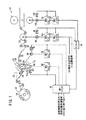
図1は、本発明の実施形態に係るカール除去装置10が組み込まれるシート体加工システム12の概略構成説明図である。
【0014】
このシート体加工システム12は、シート紙ウエブ14を巻回したロール状のシート体であるロール紙16が装着されるとともに、このロール紙16から前記シート紙ウエブ14を送り出すウエブ送り出し部18と、前記ウエブ送り出し部18から前記シート紙ウエブ14を所定の速度で送り出すメインフィード用サクションドラム20と、前記シート紙ウエブ14を切断するカッタ手段21と、本実施形態に係るカール除去装置10とを備え、前記ウエブ送り出し部18と前記サクションドラム20との間には、複数のガイドローラ22が配設される。
【0015】
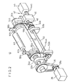
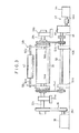
カール除去装置10は、加熱手段24を構成し誘導加熱されて感光材料ウエブ14を加熱する加熱ローラ30を備え、図2および図3に示すように、前記加熱ローラ30の両端部32a、32bが支持台34a、34bに回転自在に支持される。加熱ローラ30の端部32aには、ベルト・プーリ36を介して第1サーボモータ38の駆動軸38aが連結される。加熱ローラ30の外周には、この加熱ローラ30の周囲にシート紙ウエブ14をラップさせるとともに、前記シート紙ウエブ14のカール量に基づいて、該シート紙ウエブ14の前記加熱ローラ30の周面に対するラップ角度(ラップ時間)を変更させるスイングローラ(支持手段)40が配置される。
【0016】
スイングローラ40は、スイングローラ駆動手段42を介して加熱ローラ30に対して所定の角度位置に旋回可能に配置される。スイングローラ駆動手段42は第2サーボモータ44を備え、この第2サーボモータ44の駆動軸44aが減速機46に連結されており、この減速機46の出力軸48が回転軸50に連結されるとともに、前記回転軸50が支持台52a、52bに回転自在に支持される。
【0017】
回転軸50の両端には、ベルト・プーリ(または、ギヤ・チェーン等)54a、54bを介して旋回板56a、56bが連結され、この旋回板56a、56bが加熱ローラ30の両端部32a、32bに回転自在に配置される。旋回板56a、56bの外周部に取り付け板58a、58bが固着され、この取り付け板58a、58bにスイングローラ40の両端60a、60bが回転自在に支持される。加熱ローラ30の内部には、図1に示すように、この加熱ローラ30の温度を検出するための温度検出センサ62が配置されている。
【0018】
カール除去装置10は、加熱ローラ30およびスイングローラ40を駆動制御するデカール用の第1シーケンサ(制御手段)70と、サクションドラム20を駆動制御するドライブ用の第2シーケンサ72と、カッタ手段21を駆動制御するカッタ用の第3シーケンサ74とを備える。第1シーケンサ70には、図示しない設備シーケンサから加熱時間設定信号および設備起動準備信号が入力されるとともに、この第1シーケンサ70が前記設備シーケンサに対してスイングローラ40のオフセット動作完了信号を送信する。
【0019】
第1シーケンサ70には、第1インバータ76を介して第1サーボモータ38が接続されるとともに、この第1サーボモータ38には、加熱ローラ30の回転パルス(回転速度)を検出する第1パルスジェネレータ78が設けられる。第1シーケンサ70には、第2インバータ80を介して第2サーボモータ44が接続され、この第2サーボモータ44には、スイングローラ40の位置を検出するための第2パルスジェネレータ(位置検出手段)82が設けられる。
【0020】
第2シーケンサ72に第3インバータ84が設けられ、この第3インバータ84には、サクションドラム20を回転駆動する第3サーボモータ86が接続される。第3サーボモータ86には、サクションドラム20の回転パルス、すなわち、シート紙ウエブ14の搬送速度を検出するための第3パルスジェネレータ(ライン速度検出手段)88が設けられる。第3パルスジェネレータ88により検出される回転パルスは、アイソレータ90を介して第1および第3シーケンサ70、74にメインフィード回転パルス信号として送られる。第2シーケンサ72には、図示しない設備シーケンサからライン最高速度信号およびライン起動信号が入力される。
【0021】
第3シーケンサ74には、第4インバータ92を介してカッタ手段21を駆動制御するための第4サーボモータ94が設けられるとともに、前記第4サーボモータ94には、前記カッタ手段21の位置情報を検出するための第4パルスジェネレータ96が設けられる。
【0022】
このように構成されるカール除去装置10の動作について、本発明の第1の実施形態に係るカール除去方法との関連で、図4に示すフローチャートを参照しながら以下に説明する。
【0023】
まず、デカール処理が施されるロール紙16の紙質や紙厚等のシート体情報に基づいて、シート紙ウエブ14の加熱温度および加熱時間が設定される。次いで、設備シーケンサ(図示せず)から第1シーケンサ70に加熱時間設定信号が送られ(ステップS1)、この加熱時間に対応してスイングローラ40のオフセット量が設定される(ステップS2)。
【0024】
具体的には、図5に示すように、ライン停止中のスイングローラ40は、加熱ローラ30から離間する退避位置Aに対応して配置されている。次に、設備起動準備信号が入力されると(ステップS3)、第1シーケンサ70から第2インバータ80にスイングローラ位置指令が送られる。このため、第2サーボモータ44の作用下に、スイングローラ40が、加熱ローラ30とシート紙ウエブ14とのラップ開始位置Bよりさらに前記シート紙ウエブ14をラップさせる設定位置Cに移動する(ステップS4)。
【0025】
上記のように、スイングローラ40のオフセット動作が完了すると(ステップS5中、YES)、ステップS6に進んで、第2シーケンサ72に図示しない設備シーケンサよりライン駆動信号が入力される。第2シーケンサ72は、第3インバータ84を介して第3サーボモータ86を駆動し、サクションドラム20が回転を開始する。このサクションドラム20の回転作用下に、ロール紙16から送り出されるシート紙ウエブ14の搬送速度、すなわち、ライン速度は、図6に示すように、図示しない設備シーケンサから送られるライン最高速度信号に基づいてライン速度Vmaxまで加速された後、このライン速度Vmaxで定速搬送が行われる。
【0026】
サクションドラム20によるライン速度は、第3サーボモータ86に設けられた第3パルスジェネレータ88を介して検出されており、アイソレータ90を介して第1および第3シーケンサ70、74にライン速度信号が送られる。このため、第1シーケンサ70は、第1インバータ76を介して第1サーボモータ38を駆動し、加熱ローラ30をサクションドラム20と同期して駆動するとともに、第1パルスジェネレータ78による検出信号に基づいてフィードバック制御を行う。
【0027】
ライン速度に対応するスイングローラ40のラップ量は、図7に示すように、第1変更速度VR1および第2変更速度VR2により制御される。すなわち、ライン起動開始後に、スイングローラ40のラップ量は第1変更速度VR1により制御され(ステップS7)、ライン速度が対応するラップ量位置に到達する際、第1の実施形態では、ライン速度V1に到達する際(ステップS8中、YES)、ステップS9に進んで前記スイングローラ40のラップ量が第2変更速度VR2で追従制御される。
【0028】
スイングローラ40のラップ量を変更する際には、図2および図3に示すように、第2サーボモータ44の駆動作用下に駆動軸44a、減速機46および出力軸48を介して回転軸50が回転される。この回転軸50には、ベルト・プーリ54a、54bを介して旋回板56a、56bが連結されており、前記回転軸50の回転作用下に前記旋回板56a、56bに支持されたスイングローラ40が、加熱ローラ30の外周に対して所定の角度位置に配置される。このため、スイングローラ40の外周に保持されているシート紙ウエブ14は、加熱ローラ30の周面に所定のラップ角度でラップされる。
【0029】
一方、サクションドラム20によるライン速度Vが、図8に示すように、Vmaxから減速する際には、スイングローラ40のラップ量は、図9に示すように、ライン速度VSに至るまで第3変更速度VR3に沿って追従制御される。そして、このライン速度VS以下になると(ステップS10中、YES)、ラップ量が第4変更速度VR4に沿って制御され、前記スイングローラ40が退避位置Aに位置決めされる(ステップS11)。
【0030】
このように、第1の実施形態では、ライン立ち上がり時のライン速度Vが加速される際において、およびライン速度Vが減速されるライン停止直前において、シート紙ウエブ14が加熱ローラ30の周面に接触する長さを変更することにより、前記シート紙ウエブ14が前記加熱ローラ30に接触する時間(加熱時間)を一定に制御している。
【0031】
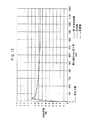
具体的には、図7に示すように、ライン速度VmaxをVmax=70m/min、加速時間を8秒、加熱時間を0.7秒、勾配変化速度V1をV1=9m/min、初期ラップ量L0をL0=30mm、および、初期ラップ時間を0.4秒に設定し、従来方法と比較する実験を行ったところ、図10に示す結果が得られた。これにより、第1の実施形態では、特にライン速度の変化率の大きい加速時のライン立ち上がり近傍では、予め所定のラップ量L0(30mm)に設定することにより、加熱開始位置近傍でのシート紙ウエブ14の加熱時間を有効に確保することができ、前記シート紙ウエブ14のデカール効果を確実に得ることが可能になる。
【0032】
一方、ライン速度の減速時には、図9に示すように、ライン速度VmaxをVmax=70m/min、減速時間tsをts=8秒、加熱時間を0.7秒、および、ラップ離脱速度VSをVS=12.25m/minに設定し、従来方法と比較する実験を行った。この結果が図11に示されており、第1の実施形態では、特に、ライン速度停止位置近傍で必要以上の加熱時間を設けることがなく、シート紙ウエブ14の品質低下等を確実に阻止して良好なデカール処理が遂行されるという効果がある。
【0033】
従って、第1の実施形態では、シート紙ウエブ14の種類に応じて処理速度を変更したり、頻繁にライン速度の加減速や停止を繰り返したりする場合においても、所望のデカール効果を確実に得ることが可能になるという利点がある。特に、ライン速度Vを連続的に無数に設定可能な場合や、処理途中でライン速度の変更を頻繁に行うような場合であっても、カール除去処理を効率的に遂行することができる。
【0034】
次に、本発明の第2の実施形態に係るカール除去方法について、以下に説明する。なお、この第2の実施形態では、第1の実施形態と同様にカール除去装置10が組み込まれるシート体加工システム12が用いられる。
【0035】
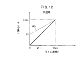
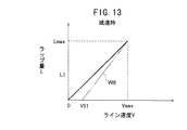
第2の実施形態では、図12に示すように、オフセット量であるスイングローラ40のラップ量L1が設定されており、ライン起動開始に伴ってラップ量が変更速度VR5に沿って制御される。一方、ライン速度の減速時には、図13に示すように、ラップ量が変更速度VR6に沿って制御され、ライン速度VS1でラップ離脱がなされている。
【0036】
そこで、図12において、ライン速度VmaxをVmax=70m/min、加速時間を8秒、加熱時間を0.7秒、初期ラップ量L1をL1=40mm、および、初期ラップ時間を0.5秒に設定し、従来方法と比較する実験を行った。その結果、図14に示すように、従来では、加熱開始直後で加熱時間が著しく低下したのに対し、第2の実施形態では、加熱時間を有効に維持して加熱開始直後からシート紙ウエブ14に対し均一な加熱時間を確保することができ、カール除去処理が効率的に遂行されるという効果が得られる。
【0037】
一方、図13において、ライン速度VmaxをVmax=70m/min、減速時間を8秒、加熱時間を0.7秒、および、ラップ離脱速度VS1をVS1=6.42/minに設定し、従来の加熱時間と比較する実験を行った。その結果、図15に示すように、第2の実施形態では、特にライン速度停止位置近傍においても所望の加熱時間を維持することができ、ライン開始から停止までの間、シート紙ウエブ14に対して均一な加熱時間を維持することが可能になり、カール除去処理が効率的かつ高精度に遂行される等、上述した第1の実施形態と同様の効果が得られる。
【0038】
また、本発明の第3の実施形態に係るカール除去方法について、以下に説明する。
【0039】
この第3の実施形態では、ライン速度の加速時に、図16に示すようなラップ量の制御が行われる。具体的には、ライン速度Vが0からライン速度V11に加速されるまでの間、ラップ量が第1変更速度VR7に沿ってラップ量L2に至るまで制御された後、このラップ量L2に対応するライン速度V11からライン速度Vmaxに至るまでの間、前記ラップ量が第2変更速度VR8に沿って制御される。なお、ライン速度の減速時には、第2の実施形態と同様の制御が行われる。
【0040】
そこで、ライン速度VmaxをVmax=70m/min、加速時間を8秒、加熱時間を0.7秒、勾配変化速度V11をV11=5m/min、および、勾配変化ラップ量L2をL2=95mmに設定し、従来の加熱時間との変化を検出する実験を行った。その結果、図17に示すように、第3の実施形態では、ライン起動開始時近傍でのシート紙ウエブ14の加熱時間を有効に維持することができ、カール除去処理が効率的に遂行される等、上述した第1および第2の実施形態と同様の効果が得られる。
【0041】
さらに、第2および第3の実施形態では、特にライン速度が非連続的な数種の値に設定することができ、搬送途中でライン速度の変更が行われない場合に、シート紙ウエブ14の品質およびカール除去効果の面から好適に使用し得るという利点がある。
【0042】
次に、本発明の第4の実施形態に係るカール除去方法について、以下に説明する。
【0043】
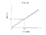
図18に示すように、ライン速度の加速時には、ライン起動開始前にスイングローラ40のラップ量L3が設定されており、サクションドラム20の回転作用下にラインが立ち上げられる。そして、ライン速度がオフセット位置に対応する速度V12に至ると、スイングローラ40が駆動されてこのスイングローラ40の位置がライン速度に追従して制御される。これにより、ライン起動開始直後の加熱時間不足を回避することができ、カール除去処理を効率的に遂行することが可能になる等、上述した第1〜第3の実施形態と同様の効果が得られる。
【0044】
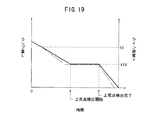
一方、ライン速度の減速時には、図19に示すようなラップ量の制御が行われる。その際、ライン速度Vに対応してスイングローラ40のラップ量が漸減しており、このライン速度が、例えば、10m/min以下になったところから、予め設定された動作速度でスイングローラ40がクリープ速度V13に対応して制御される。次いで、カッタ手段21の上死点検出が開始され、このカッタ手段21が上死点に至ったことが第4パルスジェネレータ96からのパルス信号に基づいて検出されると、前記スイングローラ40が所定の退避位置に位置決めされる。
【0045】
従って、第4の実施形態では、ライン速度が減速して停止する直前までシート紙ウエブ14の加熱時間を均一化することができ、カール除去処理が効率的に遂行される等、上述した第1〜第3の実施形態と同様の効果が得られる。しかも、カッタ手段21は、常に、上死点位置に配置されることになり、シート紙ウエブ14の切断作業が精度よくかつ確実に遂行される。
【0046】
なお、本発明の第1〜第4の実施形態では、シート体としてシート紙ウエブ14を用いて説明したが、これに限定されるものではなく、例えば、感熱紙、感圧紙、あるいは写真記録材料等の画像記録担体等、種々のシート体に適用することが可能である。
【0047】
【発明の効果】
本発明に係るシート体のカール除去方法および装置では、シート体の搬送速度が変化する際にこのシート体が加熱手段に接触する長さを変更し、前記シート体が前記加熱手段に接触する時間を一定に制御することにより、加熱時間の変動を阻止して前記シート体のカール除去処理を効率的かつ高精度に遂行することが可能となる。
【図面の簡単な説明】
【図1】本発明の実施形態に係るカール除去装置が組み込まれるシート体加工システムの概略構成説明図である。
【図2】前記カール除去装置を構成する加熱ローラおよびスイングローラの斜視説明図である。
【図3】前記加熱ローラおよび前記スイングローラの側面説明図である。
【図4】本発明の第1の実施形態に係るカール除去方法を説明するフローチャートである。
【図5】加速時のスイングローラの位置説明図である。
【図6】加速時のライン速度の説明図である。
【図7】加速時のラップ量の制御説明図である。
【図8】減速時のライン速度の説明図である。
【図9】減速時のラップ量の制御説明図である。
【図10】加速時の加熱時間の説明図である。
【図11】減速時の加熱時間の説明図である。
【図12】本発明の第2の実施形態に係るカール除去方法における加速時のラップ量の制御説明図である。
【図13】第2の実施形態に係るカール除去方法におけるラップ量の制御説明図である。
【図14】第2の実施形態における加速時の加熱時間の説明図である。
【図15】第2の実施形態における減速時の加熱時間の説明図である。
【図16】本発明の第3の実施形態に係るカール除去方法におけるラップ量の制御説明図である。
【図17】第3の実施形態における加熱時間の説明図である。
【図18】本発明の第4の実施形態に係るカール除去方法における加速時のラップ量の制御説明図である。
【図19】第4の実施形態に係るカール除去方法における減速時のラップ量の制御説明図である。
【符号の説明】
10…カール除去装置 12…シート体加工システム
14…シート紙ウエブ 16…ロール紙
18…ウエブ送り出し部 20…サクションドラム
21…カッタ手段 30…加熱ローラ
38、44、86、94…サーボモータ
40…スイングローラ 42…スイングローラ駆動手段
70、72、74…シーケンサ
76、80、84、92…インバータ
78、82、88、96…パルスジェネレータ
90…アイソレータ[0001]
BACKGROUND OF THE INVENTION
The present invention relates to a sheet body decurling method and apparatus for removing curl from the sheet body by bringing the sheet body into contact with a heating means maintained at a constant temperature.
[0002]
[Prior art]
As a sheet body obtained by winding a long sheet body web such as various photosensitive materials and paper materials into a roll, roll materials such as a roll sensitive material and roll paper are widely used. This type of roll material is easily imparted with curl (hereinafter referred to as curl) over time in the roll state, and the curl may remain on the sheet body after the sheet processing step such as cutting. For this reason, there exists a problem that the conveyance property and integration | stacking property of a sheet | seat body deteriorate remarkably.
[0003]
Therefore, various proposals have been made to remove this type of curl. For example, in Japanese Patent Laid-Open No. 6-64808, a rotatable half-moon shaft is used, and a radius is used when a workpiece (sheet body) is fed. The small shaft portion abuts against the workpiece to remove the curl of the workpiece, and when the feed is stopped, the shaft portion having a large radius abuts against the workpiece and prevents the workpiece from being reversely curled. ing. That is, the curl removing means is switched in accordance with the operation and stop of the line, thereby preventing the workpiece from being given a reverse curl (reverse curl).
[0004]
[Problems to be solved by the invention]
However, in a device that performs curl removal, the processing speed may be changed depending on the type of workpiece, and the acceleration / deceleration and stop of the processing speed may be frequently repeated. The problem of not being able to apply is pointed out. This is because, when the processing speed of the workpiece changes, the curl removal (decurl) effect also changes, and the desired curl removal processing cannot be performed efficiently.
[0005]
The present invention solves this type of problem, and provides a sheet body curl removal method and apparatus that can reliably and easily remove the curl of a sheet body without being affected by changes in processing speed. The purpose is to provide.
[0006]
[Means for Solving the Problems]
In the sheet body curl removing method and apparatus according to the present invention, when the sheet body moves at a predetermined conveyance speed, the sheet body is brought into contact with the heating means for a predetermined length to remove the curl from the sheet body. Processing is performed. And when the conveyance speed of a sheet body changes, the time which the said sheet body contacts the said heating means is controlled uniformly by changing the length which the said sheet body contacts a heating means. For this reason, even if the processing speed including the conveyance speed of the sheet body is changed according to the type of the sheet body, or frequent acceleration / deceleration and stop are repeated, the heating time of the sheet body is kept constant. In addition, the decurling process is performed efficiently and with high accuracy by making the heating conditions uniform.
[0007]
At that time, the sheet body is accelerated to a predetermined conveying speed in a state where the sheet body is in contact with the heating unit for a predetermined length before the conveyance of the sheet body is started, and the sheet body is in contact with the heating unit. The length to be changed. As a result, the sheet body can be effectively heated at the time of line rising, which is the acceleration of the sheet body, which is likely to shorten the contact time (heating time), and from the acceleration to the constant speed conveyance with simple control. Since the heating time of the sheet body is made uniform, the decurling process is reliably performed.
[0008]
Further, after the sheet body is started to be conveyed, the sheet body is accelerated to a predetermined conveyance speed, and the length changing speed at which the sheet body contacts the heating means is switched and controlled in at least two stages. Therefore, in the region from the start of line operation to a predetermined speed, the change speed of the contact length of the sheet body can be increased, and the decrease in the decurling effect due to insufficient contact time at the start of acceleration is effectively prevented. It becomes possible to do.
[0009]
Furthermore, when the conveyance speed of the sheet body is decelerated to a predetermined conveyance speed or less, the length of contact of the sheet body with the heating unit is reduced along a predetermined change speed. For this reason, non-uniformity of the contact time of the sheet body due to the reduction of the line speed is prevented, and the sheet body can be reliably heat-treated with the desired contact time with respect to the heating means, and the curl removal process is efficient Done.
[0010]
Furthermore, while the conveyance speed of the sheet body is decelerated, the change speed of the length at which the sheet body contacts the heating means is switched and controlled in at least two stages. Accordingly, even when the line speed is arbitrarily changed, it is possible to effectively cope with the curl removal processing of the sheet body.
[0011]
Further, the heating means has a heating roller for wrapping the sheet body on the circumferential surface, and the sheet body is wrapped on the circumferential surface of the heating roller via a swing roller. Then, by controlling the wrap angle of the sheet member, the length of the sheet member contacting the peripheral surface of the heating roller is changed. Therefore, it is possible to easily cope with a change in the conveyance speed of the sheet body with a simple process and configuration, and the curl removal processing of the sheet body is effectively performed.
[0012]
Here, since the contact length of the sheet body with respect to the peripheral surface of the heating roller is performed by controlling the wrap angle by the swing roller, the configuration and control are simplified at a time. At that time, the swing shaft of the swing roller is set coaxially with the rotation shaft of the heating roller, and the control of the wrap angle of the sheet member by the swing roller can be performed more easily and accurately.
[0013]
DETAILED DESCRIPTION OF THE INVENTION
FIG. 1 is a schematic configuration explanatory diagram of a sheet body processing system 12 in which a
[0014]
The sheet body processing system 12 is provided with a roll paper 16 that is a roll-shaped sheet body around which the
[0015]
The
[0016]
The
[0017]
Revolving
[0018]
The
[0019]
A
[0020]
A
[0021]
The third sequencer 74 is provided with a
[0022]
The operation of the
[0023]
First, the heating temperature and heating time of the
[0024]
Specifically, as shown in FIG. 5, the
[0025]
As described above, when the offset operation of the
[0026]
The line speed by the
[0027]
The wrap amount of the
[0028]
When changing the lap amount of the
[0029]
On the other hand, when the line speed V by the
[0030]
As described above, in the first embodiment, when the line speed V at the time of line rise is accelerated and immediately before the line stop when the line speed V is decelerated, the
[0031]
Specifically, as shown in FIG. 7, the line speed Vmax is Vmax = 70 m / min, the acceleration time is 8 seconds, the heating time is 0.7 seconds, the gradient change speed V1 is V1 = 9 m / min, and the initial lap amount When L0 was set to L0 = 30 mm and the initial lap time was set to 0.4 seconds and an experiment was performed for comparison with the conventional method, the result shown in FIG. 10 was obtained. Accordingly, in the first embodiment, particularly in the vicinity of the line rising at the time of acceleration with a large rate of change of the line speed, the sheet paper web in the vicinity of the heating start position is set in advance by setting a predetermined lap amount L0 (30 mm). The heating time of 14 can be ensured effectively, and the decurling effect of the
[0032]
On the other hand, at the time of deceleration of the line speed, as shown in FIG. 9, the line speed Vmax is Vmax = 70 m / min, the deceleration time ts is ts = 8 seconds, the heating time is 0.7 seconds, and the lap separation speed VS is VS. = 12.25 m / min was set, and an experiment for comparison with the conventional method was performed. This result is shown in FIG. 11. In the first embodiment, the heating time more than necessary is not provided near the line speed stop position, and the deterioration of the quality of the
[0033]
Therefore, in the first embodiment, even when the processing speed is changed according to the type of the
[0034]
Next, a decurling method according to the second embodiment of the present invention will be described below. In the second embodiment, a sheet body processing system 12 in which the
[0035]
In the second embodiment, as shown in FIG. 12, a lap amount L1 of the
[0036]
Therefore, in FIG. 12, the line speed Vmax is Vmax = 70 m / min, the acceleration time is 8 seconds, the heating time is 0.7 seconds, the initial lap amount L1 is L1 = 40 mm, and the initial lap time is 0.5 seconds. An experiment was conducted to set and compare with the conventional method. As a result, as shown in FIG. 14, in the related art, the heating time is remarkably reduced immediately after the start of heating, whereas in the second embodiment, the heating time is effectively maintained and the
[0037]
On the other hand, in FIG. 13, the line speed Vmax is set to Vmax = 70 m / min, the deceleration time is set to 8 seconds, the heating time is set to 0.7 seconds, and the lap release speed VS1 is set to VS1 = 6.42 / min. Experiments were performed to compare with heating time. As a result, as shown in FIG. 15, in the second embodiment, a desired heating time can be maintained even near the line speed stop position, and the
[0038]
Further, a decurling method according to the third embodiment of the present invention will be described below.
[0039]
In the third embodiment, the lap amount is controlled as shown in FIG. 16 when the line speed is accelerated. Specifically, until the line speed V is accelerated from 0 to the line speed V11, the lap amount is controlled to reach the lap amount L2 along the first change speed VR7, and then corresponds to the lap amount L2. The lap amount is controlled along the second change speed VR8 from the line speed V11 to the line speed Vmax. When the line speed is reduced, the same control as that in the second embodiment is performed.
[0040]
Therefore, the line speed Vmax is set to Vmax = 70 m / min, the acceleration time is set to 8 seconds, the heating time is set to 0.7 seconds, the gradient change speed V11 is set to V11 = 5 m / min, and the gradient change lap amount L2 is set to L2 = 95 mm. Then, an experiment was conducted to detect a change from the conventional heating time. As a result, as shown in FIG. 17, in the third embodiment, the heating time of the
[0041]
Furthermore, in the second and third embodiments, the line speed can be set to several discontinuous values in particular, and when the line speed is not changed during the conveyance, the
[0042]
Next, a decurling method according to a fourth embodiment of the present invention will be described below.
[0043]
As shown in FIG. 18, when the line speed is accelerated, the lap amount L3 of the
[0044]
On the other hand, when the line speed is decelerated, the lap amount as shown in FIG. 19 is controlled. At that time, the amount of lap of the
[0045]
Therefore, in the fourth embodiment, the heating time of the
[0046]
In the first to fourth embodiments of the present invention, the
[0047]
【The invention's effect】
In the sheet body decurling method and apparatus according to the present invention, when the sheet body conveyance speed changes, the length of contact of the sheet body with the heating means is changed, and the time during which the sheet body contacts the heating means. It is possible to perform the curl removal processing of the sheet body efficiently and with high accuracy by preventing the fluctuation of the heating time by controlling the constant.
[Brief description of the drawings]
FIG. 1 is a schematic configuration explanatory diagram of a sheet body processing system in which a curl removal apparatus according to an embodiment of the present invention is incorporated.
FIG. 2 is a perspective explanatory view of a heating roller and a swing roller constituting the decurling device.
FIG. 3 is an explanatory side view of the heating roller and the swing roller.
FIG. 4 is a flowchart illustrating a curl removal method according to the first embodiment of the present invention.
FIG. 5 is an explanatory view of the position of the swing roller during acceleration.
FIG. 6 is an explanatory diagram of a line speed during acceleration.
FIG. 7 is an explanatory diagram of control of a lap amount during acceleration.
FIG. 8 is an explanatory diagram of a line speed during deceleration.
FIG. 9 is an explanatory diagram of control of a lap amount during deceleration.
FIG. 10 is an explanatory diagram of a heating time during acceleration.
FIG. 11 is an explanatory diagram of a heating time during deceleration.
FIG. 12 is a control explanatory diagram of a lap amount during acceleration in the decurling method according to the second embodiment of the present invention.
FIG. 13 is an explanatory diagram of control of a lap amount in the curl removing method according to the second embodiment.
FIG. 14 is an explanatory diagram of a heating time during acceleration in the second embodiment.
FIG. 15 is an explanatory diagram of a heating time during deceleration in the second embodiment.
FIG. 16 is an explanatory diagram of wrap amount control in a decurling method according to a third embodiment of the present invention.
FIG. 17 is an explanatory diagram of a heating time in the third embodiment.
FIG. 18 is an explanatory diagram for controlling the lap amount during acceleration in the decurling method according to the fourth embodiment of the present invention.
FIG. 19 is a control explanatory diagram of a lap amount at the time of deceleration in the decurling method according to the fourth embodiment.
[Explanation of symbols]
DESCRIPTION OF
Claims (9)
前記シート体が所定の搬送速度で移動する際に、該シート体を前記加熱手段に対して所定の長さだけ接触させる工程と、
前記シート体の搬送速度が変化する際に、該シート体が前記加熱手段に接触する長さを変更することにより、前記シート体が前記加熱手段に接触する時間を一定に制御する工程と、
を有することを特徴とするシート体のカール除去方法。A sheet body curl removal method for removing curl of the sheet body by contacting the sheet body with a heating means maintained at a constant temperature,
A step of bringing the sheet body into contact with the heating means by a predetermined length when the sheet body moves at a predetermined conveyance speed;
A step of controlling the time during which the sheet body is in contact with the heating means by changing the length that the sheet body is in contact with the heating means when the conveyance speed of the sheet body is changed; and
A method for removing curl from a sheet, comprising:
前記シート体が前記加熱手段に接触する長さの変更速度を、少なくとも2段階に切り替え制御することを特徴とするシート体のカール除去方法。The curl removal method according to claim 1, wherein the sheet body is accelerated to a predetermined conveyance speed after the conveyance of the sheet body is started.
A method of removing curl from a sheet body, wherein the speed of changing the length of contact of the sheet body with the heating means is controlled in at least two stages.
スイングローラを介して前記加熱ローラの周面に前記シート体をラップさせるラップ角度を制御することにより、該シート体が該加熱ローラの周面に接触する長さを変更することを特徴とするシート体のカール除去方法。The curl removing method according to any one of claims 1 to 5, wherein the heating unit includes a heating roller that wraps the sheet body on a peripheral surface,
By controlling a wrap angle at which the sheet body is wrapped on the circumferential surface of the heating roller via a swing roller, the length of the sheet body contacting the circumferential surface of the heating roller is changed. Body decurling method.
前記シート体の搬送速度を検出するライン速度検出手段と、
前記シート体を前記加熱手段に所定の長さだけ接触させる支持手段と、
前記支持手段の位置を検出する位置検出手段と、
前記シート体の搬送速度が変化する際に、該シート体が前記加熱手段に接触する長さを変更して前記シート体が前記加熱手段に接触する時間を一定に制御するために、前記シート体の搬送速度変化に対応して前記支持手段を駆動制御する制御手段と、
を備えることを特徴とするシート体のカール除去装置。A decurling device for a sheet body for removing the curl of the sheet body by bringing the sheet body into contact with a heating means maintained at a constant temperature,
A line speed detecting means for detecting a conveying speed of the sheet body;
Support means for bringing the sheet body into contact with the heating means for a predetermined length;
Position detection means for detecting the position of the support means;
In order to control the time during which the sheet body contacts the heating unit by changing the length of the sheet body contacting the heating unit when the conveyance speed of the sheet body changes, the sheet body is controlled Control means for driving and controlling the support means in response to a change in the conveyance speed of
A decurling device for a sheet body, comprising:
前記支持手段は、前記加熱ローラの周面に前記シート体をラップさせるとともに、前記シート体の前記加熱ローラの周面に対するラップ角度を変更可能なスイングローラを備えることを特徴とするシート体のカール除去装置。The decurling apparatus according to claim 7, wherein the heating means includes a rotatable heating roller,
The curling of the sheet body, characterized in that the support means includes a swing roller that wraps the sheet body on the circumferential surface of the heating roller and can change a wrap angle of the sheet body with respect to the circumferential surface of the heating roller. Removal device.
Priority Applications (12)
| Application Number | Priority Date | Filing Date | Title |
|---|---|---|---|
| JP2000093618A JP4150146B2 (en) | 2000-03-30 | 2000-03-30 | Sheet body curl removal method and apparatus |
| EP20050006018 EP1541301B1 (en) | 1999-10-01 | 2000-09-29 | Sheet material cutting method for cutting a thermal imaging material and sheet material cutting apparatus for cutting a band-shaped thermal imaging material |
| DE2000637149 DE60037149T2 (en) | 1999-10-01 | 2000-09-29 | Method and device for cutting a band-shaped thermal recording material |
| DE2000621326 DE60021326T2 (en) | 1999-10-01 | 2000-09-29 | Method and apparatus for correcting the deformation of sheet materials |
| EP20000121459 EP1088644B1 (en) | 1999-10-01 | 2000-09-29 | Deformation correcting method and apparatus for sheet materials |
| EP20060003987 EP1679162B1 (en) | 1999-10-01 | 2000-09-29 | Sheet material cutting apparatus for cutting a band-shaped thermal imaging material |
| DE60041794T DE60041794D1 (en) | 1999-10-01 | 2000-09-29 | Apparatus for cutting ribbon-shaped thermal image material |
| AT00121459T ATE299795T1 (en) | 1999-10-01 | 2000-09-29 | METHOD AND APPARATUS FOR CORRECTING DEFORMATION OF SHEET MATERIALS |
| US09/676,667 US6613253B1 (en) | 1999-10-01 | 2000-10-02 | Deformation correcting method, cutting method, deformation correcting apparatus and cutting apparatus for sheet materials |
| CNB001296736A CN1262408C (en) | 1999-10-01 | 2000-10-08 | Deformed correcting method and cutting method, deformed correcting and cutting devices for thin sheet body |
| US10/428,778 US7182008B2 (en) | 1999-10-01 | 2003-05-05 | Sheet material cutting method for cutting thermal imaging material |
| US11/638,578 US20070221024A1 (en) | 1999-10-01 | 2006-12-14 | Sheet material cutting apparatus for cutting thermal imaging material |
Applications Claiming Priority (1)
| Application Number | Priority Date | Filing Date | Title |
|---|---|---|---|
| JP2000093618A JP4150146B2 (en) | 2000-03-30 | 2000-03-30 | Sheet body curl removal method and apparatus |
Publications (3)
| Publication Number | Publication Date |
|---|---|
| JP2001278519A JP2001278519A (en) | 2001-10-10 |
| JP2001278519A5 JP2001278519A5 (en) | 2005-11-17 |
| JP4150146B2 true JP4150146B2 (en) | 2008-09-17 |
Family
ID=18608777
Family Applications (1)
| Application Number | Title | Priority Date | Filing Date |
|---|---|---|---|
| JP2000093618A Expired - Fee Related JP4150146B2 (en) | 1999-10-01 | 2000-03-30 | Sheet body curl removal method and apparatus |
Country Status (1)
| Country | Link |
|---|---|
| JP (1) | JP4150146B2 (en) |
Families Citing this family (1)
| Publication number | Priority date | Publication date | Assignee | Title |
|---|---|---|---|---|
| JP5658989B2 (en) * | 2010-12-14 | 2015-01-28 | リンテック株式会社 | Printing device |
-
2000
- 2000-03-30 JP JP2000093618A patent/JP4150146B2/en not_active Expired - Fee Related
Also Published As
| Publication number | Publication date |
|---|---|
| JP2001278519A (en) | 2001-10-10 |
Similar Documents
| Publication | Publication Date | Title |
|---|---|---|
| US5249758A (en) | Apparatus for the continuous winding of a web of sheet-like material, in particular a paper web | |
| JP6249011B2 (en) | Winder and method for producing rolls of web material | |
| EP1088644B1 (en) | Deformation correcting method and apparatus for sheet materials | |
| JP2948908B2 (en) | Unwinding machine and method for forming a roll of web material with apparatus for cutting web material | |
| JP3445822B2 (en) | Rewinding machine and method for producing logs of coreless web material | |
| US8671810B2 (en) | Folder for adjustably tensioning a web as the web is cut | |
| JPH0777766B2 (en) | Winding method and device for tire component | |
| US4517042A (en) | Method and apparatus for decurling laminated stock | |
| JPH0432733B2 (en) | ||
| JPH08245024A (en) | Continuous take-up device for sheet material to be taken up | |
| JP4150146B2 (en) | Sheet body curl removal method and apparatus | |
| JP2007008558A (en) | Packaging device | |
| JPH0834642A (en) | Method for transporting extended synthetic-resin film and device therefor | |
| JP2001097620A (en) | Curl eliminating method and device for image recording carrier | |
| JPS63106264A (en) | Supply device for small-width belt-shaped object | |
| JP2001278520A (en) | Method and device for correcting deformation of high molecular sheet body | |
| JPH03266668A (en) | Recording on continuous recording paper | |
| JP2001063883A (en) | Manufacture of sheet roll body | |
| JP2001226009A (en) | Curl removing method and device for rolled sheet | |
| JP2003104592A (en) | Hoop material delivering device | |
| JP2002220145A (en) | Web heating device | |
| JP2001310850A (en) | Method and device for eliminating curl of recording medium | |
| JP3076714U (en) | Thermoforming equipment for thin and thick resin sheets | |
| JP3276279B2 (en) | Pinch roll control device | |
| JP2628431B2 (en) | Cloth supply device for cutting machine |
Legal Events
| Date | Code | Title | Description |
|---|---|---|---|
| A521 | Written amendment |
Free format text: JAPANESE INTERMEDIATE CODE: A523 Effective date: 20050930 |
|
| A621 | Written request for application examination |
Free format text: JAPANESE INTERMEDIATE CODE: A621 Effective date: 20050930 |
|
| A711 | Notification of change in applicant |
Free format text: JAPANESE INTERMEDIATE CODE: A712 Effective date: 20061208 |
|
| TRDD | Decision of grant or rejection written | ||
| A01 | Written decision to grant a patent or to grant a registration (utility model) |
Free format text: JAPANESE INTERMEDIATE CODE: A01 Effective date: 20080624 |
|
| A01 | Written decision to grant a patent or to grant a registration (utility model) |
Free format text: JAPANESE INTERMEDIATE CODE: A01 |
|
| A61 | First payment of annual fees (during grant procedure) |
Free format text: JAPANESE INTERMEDIATE CODE: A61 Effective date: 20080627 |
|
| FPAY | Renewal fee payment (event date is renewal date of database) |
Free format text: PAYMENT UNTIL: 20110704 Year of fee payment: 3 |
|
| R150 | Certificate of patent or registration of utility model |
Free format text: JAPANESE INTERMEDIATE CODE: R150 |
|
| FPAY | Renewal fee payment (event date is renewal date of database) |
Free format text: PAYMENT UNTIL: 20110704 Year of fee payment: 3 |
|
| FPAY | Renewal fee payment (event date is renewal date of database) |
Free format text: PAYMENT UNTIL: 20120704 Year of fee payment: 4 |
|
| FPAY | Renewal fee payment (event date is renewal date of database) |
Free format text: PAYMENT UNTIL: 20120704 Year of fee payment: 4 |
|
| FPAY | Renewal fee payment (event date is renewal date of database) |
Free format text: PAYMENT UNTIL: 20130704 Year of fee payment: 5 |
|
| LAPS | Cancellation because of no payment of annual fees |