JP4149548B2 - Ultrasonic probe water bag - Google Patents
Ultrasonic probe water bag Download PDFInfo
- Publication number
- JP4149548B2 JP4149548B2 JP02126898A JP2126898A JP4149548B2 JP 4149548 B2 JP4149548 B2 JP 4149548B2 JP 02126898 A JP02126898 A JP 02126898A JP 2126898 A JP2126898 A JP 2126898A JP 4149548 B2 JP4149548 B2 JP 4149548B2
- Authority
- JP
- Japan
- Prior art keywords
- water bag
- probe
- film
- water
- ultrasonic probe
- Prior art date
- Legal status (The legal status is an assumption and is not a legal conclusion. Google has not performed a legal analysis and makes no representation as to the accuracy of the status listed.)
- Expired - Fee Related
Links
Images


Description
【0001】
【発明の属する技術分野】
本発明は、凹凸を有する被検体と超音波プローブとの接触性を高め超音波画質を向上させるため超音波プローブに装着される超音波プローブ用水袋に関する。
【0002】
【従来の技術】
従来より、乳腺、甲状腺、新生児の頭部等の凹凸の大きい部位の超音波診断には、超音波プローブと被検体との間に水袋を配置して、超音波プローブと被検体との音響的整合をとっていた。
【0003】
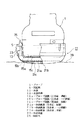
この従来の超音波プローブ用水袋は、例えば図6に示すように、外枠にプローブ側膜と体表側膜とを接着して袋状を形成し外枠に注水バルブを設けた構成となっていた。そして、プローブ側膜全体が薄く形成されており、体表側膜は平坦で四方の端部が接着面の剛性と兼ねてプローブ側膜よりも厚くしてあった。
【0004】
超音波プローブ用水袋を超音波プローブに装着するには、まず水袋内を滅菌水で満水にさせ、エア抜きをして注排水栓を締める。この状態の水袋は、厚さが薄いプローブ側膜全体が膨らんだ形状となる。そこで水袋をプローブに装着するとプローブ側膜がプローブの前面によって押し込まれ、水袋内の水圧が上がる。ところが、体表側膜は平坦で四方の剛性が高いので、ある程度膜が膨らんで水圧の上昇を吸収するもののある限度以上は、水袋内の水圧が高くなり、今度は水袋外枠と膜の接着部(プローブ側・体表側共)に負担がかかるので、水漏れ・亀裂の心配や水圧が高くて装着出来ない場合があった。
【0005】
そのため、更なる作業として、水袋にプローブを装着させながら注排水栓を緩めて排水し、適度の膨らみになったところで注排水栓を締める。排水し過ぎたときはもう一度満水にして排水調整するという作業をしていた。
【0006】
【発明が解決しようとする課題】
しかしながら、一旦満水にした水袋を排水しながらプローブに装着し、適度な膨らみとなったところで注排水栓を締めるという作業は、水袋のプローブへの装着と水袋の水量の調節という2つの作業を同時に行わないと適切な水量とならないので、未熟な作業者は、排水し過ぎたときはもう一度満水にして水袋を装着しながら排水調整するという作業を繰り返さねばならず、煩雑な作業となるという問題点があった。
【0007】
以上の問題点に鑑み本発明の目的は、前記のような煩わしい水量調節作業をなくし操作性を向上させた超音波プローブ用水袋を提供することである。
【0008】
【課題を解決するための手段】
上記目的を達成するために本発明は、超音波プローブに接触する側の第1膜及び被検体に接触する側の第2膜を備え内部に音響伝達液が封入される超音波プローブ用水袋において、前記超音波プローブから第1膜に超音波が入射する入射部が薄く形成され、この入射部以外の第1膜には厚く形成された部分を含むことを要旨とする超音波プローブ用水袋である。
【0009】
また本発明は、前記超音波プローブ用水袋において、前記第2膜は、被検体に接する底部及び該底部に続く側面の所定の高さまで回り込む側面回り込み部を有し、前記底部及び側面回り込み部が均一の厚さで形成されたことを要旨とする。
【0012】
【発明の実施の形態】
次に図面を参照して、本発明の実施の形態を詳細に説明する。
図1は、本発明に係る超音波プローブ用水袋(以下、単に水袋と略す)の形状を説明する部分断面正面図(a)及び部分断面側面図(b)である。
【0013】
超音波プローブ(以下、単にプローブと略す)1に装着される水袋11は、プローブ1に接触する側に設けられたシリコンゴム製のプローブ側膜15、図示されない被検体の体表に接触する側に設けられたシリコンゴム製の体表側膜21、プローブ側膜15及び体表側膜21の周辺部が水密に接着された硬質のプラスチックで形成された水袋外枠13、水袋外枠13に設けられた注排水口35を封止する注排水口栓23を備えている。
【0014】
水袋外枠13から上方に伸延する固定外枠13aには、上端部から下方へ4箇所の切り込みが入れられ、スリット部13bが形成されている。水袋11をプローブ1に取り付ける際には、このスリット部13bが開くことによって、4分割された固定外枠13aの上端部がある程度外側に押し広げられ、固定外枠13aの内側に設けられた固定爪25がプローブ1の外周部に設けられた突起部5を乗り越えて、引っかかることにより固定される。
【0015】
プローブ側膜15は、超音波画像上の妨げにならないように、プローブ先端3に設けられた超音波発射部7より大きい面積を有する薄膜部17により超音波発射部7に接している。すなわち、超音波発射部7の長さ(以下、プローブ先端長と呼ぶ)a1より薄膜部17の長さb1が長く(a1<b1)、超音波発射部7の幅(以下、プローブ先端幅と呼ぶ)a2より薄膜部17の幅b2が広く(a2<b2)なるように薄膜部17の大きさが決められている。そして、プローブ側膜15の薄膜部17の厚さを0.15mmないし0.30mmのいずれかの厚さ、例えば0.2mmに形成されている。
【0016】
また、薄膜部17以外のプローブ側膜15は、その周囲または長手・短手方向のどちらか一方(以後、「周囲」と呼ぶ)を厚くした厚膜部19として、例えば、0.9mmの厚さに形成し、膜面の剛性を持たせている。
【0017】
図2は、プローブ側膜15の詳細を示す断面図であり、プローブ1と接触した状態を示している。同図に示すように、薄膜部17の周囲の厚膜部19の厚みは、プローブ1を装着した際に薄膜部17とプローブの超音波発射部7とを均一に接触させるためにプローブ接触面17aとは反対の面(水袋内部)に突出するように設ける。このようにプローブ側膜15は、薄膜部17の周囲に厚膜部19が設けられているので、水袋11を満水にした時は薄膜部17のみが膨らむようになる。
【0018】
図3は、体表側膜21の詳細を示すとともに、プローブ側膜15及び体表側膜21の水袋外枠13への取付状態を説明する断面図である。同図に示すように、体表側膜21は、プローブ1を水袋11に装着した際の水圧を有効に体表側膜21に伝えて膨らますために、プローブ側膜15の薄膜部17の幅b1よりも大きくとり(c)、更に高さ(d)を設けて体表側膜の側面回り込み部29までを一定の膜厚、すなわち0.15mmないし0.30mmのいずれかの厚さ、例えば0.2mmに形成されている。
【0019】
図4は、第1実施形態の水袋の注水前、注水後、及びプローブ装着後のプローブ側膜及び体表側膜の形状を示す部分断面正面図である。同図において、注水前のプローブ側膜15及び体表側膜21の形状は、それぞれ15a、21aとなり、注水後の形状は、それぞれ15b、21bとなり、プローブ1に装着後の形状は、それぞれ15c、21cとなる。
【0020】
プローブ装着の際は、注排水栓23を一旦取り外し、水袋外枠13に設けられた注排水口35を上方にして、ここから脱気水または滅菌水等の音響伝達液を水袋の内部に空気が残らないように満水位となるまで注入し、注排水栓23を締める。この状態では、プローブ側膜15及び体表側膜21の形状は、それぞれ15b、21bとなる。
【0021】
特にプローブ側膜15は、超音波発射部7に接する領域よりやや広い部分のみが薄膜部17とされ、他の部分には、厚膜部19が設けられているので、水圧による膨らみは、薄膜部17のみに限定されるとともに、従来の水袋におけるプローブ側膜のように、プローブ側膜全体が水圧によって大きく膨らむことがない。このため、水袋11のプローブ側膜15及び体表側膜21に外力を加えない状態で、注排水口35から満水位まで注水した場合に、適量な水量が水袋内に注入される。
【0022】
その後、プローブ1の超音波発射部7と水袋11のプローブ側膜15との接触面に図示しない音響ゼリーを塗布し、プローブ1を水袋11に装着する。
【0023】
装着時には、水袋11のプローブ側膜15の膨らみ量以上の押し込み量によりプローブ1が水袋外枠13に押し込まれ、押し込んだ先で水袋外枠13から上方に伸延する固定外枠13aに設けられた固定爪25がプローブ1の突起部5乗り越えて引っ掛かることにより、固定ネジ等を締めることなくワンタッチで固定される。
【0024】
図5は、本発明に係る超音波プローブ用水袋の第2実施形態を説明する正面図である。本第2実施形態においては、穿刺アダプタを設けた水袋に本発明を適用した例を説明する。
【0025】
図5において、プローブ1は、第1実施形態に用いられたプローブ1と同様のものである。本実施形態の水袋11は、水袋外枠13の形状が第1実施形態の水袋外枠13と異なっている。水袋外枠13は、図示されないプローブ1の超音波発射部7と略平行な上端部と、この上端部と例えば15度の傾斜角を成す下端部を備えている。上端部には図示しないプローブ側膜、下端部には体表側膜21がそれぞれ固定され、これらの膜は第1実施形態と同様である。
【0026】
また水袋外枠13の右側には、穿刺アダプタホルダ41が設けられ、この穿刺アダプタホルダ41に着脱可能に穿刺アダプタ43が設けられる。穿刺アダプタ43は、各種の径を有する針挿通孔43aが設けられており、使用される穿刺針45の外径に応じた針挿通孔43aを有する穿刺アダプタ43が選択されて穿刺アダプタホルダ41に装着される。
【0027】
本実施の形態における水袋の注水方法及びプローブへの取付方法も第1の実施形態と同様であり、水袋11のプローブ側膜15及び体表側膜21に外力を加えない状態で、注排水口35から満水位まで注水した場合に、適量な水量が水袋内に注入され、水量調節作業は不要である。
【0028】
以上好ましい実施形態について説明したが、これらは本発明を限定するものではない。これ以外に種々の形状のプローブに適合する水袋に本発明を適用できることは明らかである。
【0029】
【発明の効果】
以上説明したように本発明によれば、水袋の膨らみを調整するための水量調節が不要となり、煩わしい注排水作業をすることなくプローブを装着出来るので、迅速な検査準備を行い、すぐに臨床に使える超音波プローブ用水袋を提供することができるという効果がある。
【0030】
また本発明によれば、超音波診断毎の水袋の膨らみ具合が一定となるので、超音波振動子から被検体の体表までの距離に再現性を持たせることができる。このため、異なる検査間の検査条件の再現性が確保されるので、超音波診断画像相互比較が容易となり、治療経過観察、患者間の症例比較等が容易となるという効果がある。
【図面の簡単な説明】
【図1】本発明に係る超音波プローブ用水袋の第1実施形態を示す部分断面正面図(a)及び部分断面側面図(b)である。
【図2】第1実施形態のプローブ側膜の詳細を示す断面図である。
【図3】第1実施形態の体表側膜の詳細を示す断面図である。
【図4】第1実施形態の水袋の注水前、注水後、及び超音波プローブに装着後の各状態を説明する部分断面正面図である。
【図5】本発明に係る超音波プローブ用水袋の第2実施形態を示す正面図である。
【図6】従来例の超音波プローブ用水袋をプローブに装着した様子を示す部分断面正面図である。
【符号の説明】
1…プローブ、3…プローブ先端、5…突起部、7…超音波発射部、9…水、11…水袋、13…水袋外枠、13a…固定外枠、13b…スリット部、15…プローブ側膜、17…薄膜部、19…厚膜部、21…体表側膜、23…注排水栓、25…固定爪 35…注排水口。[0001]
BACKGROUND OF THE INVENTION
The present invention relates to a water bag for an ultrasonic probe that is attached to an ultrasonic probe in order to improve the contact between an object having irregularities and the ultrasonic probe and improve the ultrasonic image quality.
[0002]
[Prior art]
Conventionally, for ultrasonic diagnosis of highly uneven parts such as the mammary gland, thyroid gland, and the head of a newborn baby, a water bag is placed between the ultrasonic probe and the subject, and the acoustic waves between the ultrasonic probe and the subject are detected. Was consistent.
[0003]
For example, as shown in FIG. 6, this conventional ultrasonic probe water bag has a configuration in which a probe side membrane and a body surface side membrane are bonded to an outer frame to form a bag shape, and a water injection valve is provided on the outer frame. It was. The entire probe side film was formed thin, the body surface side film was flat, and the four ends were thicker than the probe side film in combination with the rigidity of the bonding surface.
[0004]
To attach the ultrasonic probe water bag to the ultrasonic probe, first fill the water bag with sterilized water, bleed air, and tighten the pouring drain plug. The water bag in this state has a shape in which the entire thin probe-side membrane is swollen. Therefore, when the water bag is attached to the probe, the probe side membrane is pushed in by the front surface of the probe, and the water pressure in the water bag increases. However, the body surface side membrane is flat and has high rigidity in all directions, so that the membrane swells to some extent and absorbs the increase in water pressure, but the water pressure in the water bag rises above a certain limit. Since the adhesion part (both probe side and body surface side) is burdened, there were cases where it was not possible to attach due to fear of water leakage / cracking or high water pressure.
[0005]
Therefore, as a further work, loosen and drain the pouring drain plug while attaching the probe to the water bag, and tighten the pouring drain plug when it reaches an appropriate swelling. When it drained too much, it was working to make it full again and adjust the drainage.
[0006]
[Problems to be solved by the invention]
However, once the water bag is full, it is attached to the probe while draining, and the operation of tightening the pouring / draining tap at the appropriate bulge has two tasks: attaching the water bag to the probe and adjusting the amount of water in the water bag. If the work is not carried out at the same time, the amount of water will not be appropriate, so if the worker has drained too much, he will have to repeat the work of adjusting the drainage while filling the water bag again and filling the water bag. There was a problem of becoming.
[0007]
In view of the above problems, an object of the present invention is to provide a water bag for an ultrasonic probe that eliminates the troublesome water amount adjustment operation as described above and has improved operability.
[0008]
[Means for Solving the Problems]
In order to achieve the above object, the present invention provides an ultrasonic probe water bag comprising a first film in contact with an ultrasonic probe and a second film in contact with a subject, wherein an acoustic transmission liquid is enclosed therein. An ultrasonic probe water bag comprising: a thin incident portion where ultrasonic waves are incident on the first film from the ultrasonic probe; and a thick portion formed in the first film other than the incident portion. is there.
[0009]
Further, the present invention is the ultrasonic probe water bag, wherein the second film has a bottom portion in contact with the subject and a side surface wrapping portion that wraps to a predetermined height on a side surface following the bottom portion, and the bottom portion and the side surface wrapping portion are The gist is that it is formed with a uniform thickness.
[0012]
DETAILED DESCRIPTION OF THE INVENTION
Next, embodiments of the present invention will be described in detail with reference to the drawings.
FIG. 1 is a partial cross-sectional front view (a) and a partial cross-sectional side view (b) for explaining the shape of an ultrasonic probe water bag (hereinafter simply referred to as a water bag) according to the present invention.
[0013]
A
[0014]
In the fixed
[0015]
The
[0016]
Further, the
[0017]
FIG. 2 is a cross-sectional view showing details of the
[0018]
FIG. 3 is a cross-sectional view illustrating details of the body
[0019]
FIG. 4 is a partial cross-sectional front view showing the shapes of the probe side membrane and the body surface side membrane before water injection, after water injection, and after probe installation of the water bag of the first embodiment. In the figure, the shapes of the
[0020]
When the probe is attached, the pouring /
[0021]
In particular, the probe-
[0022]
Thereafter, an acoustic jelly (not shown) is applied to the contact surface between the ultrasonic
[0023]
At the time of mounting, the
[0024]
FIG. 5 is a front view for explaining a second embodiment of the ultrasonic probe water bag according to the present invention. In the second embodiment, an example in which the present invention is applied to a water bag provided with a puncture adapter will be described.
[0025]
In FIG. 5, the
[0026]
A
[0027]
The water bag injection method and the probe attachment method in the present embodiment are also the same as in the first embodiment, and in the state where no external force is applied to the
[0028]
Although preferred embodiments have been described above, they are not intended to limit the present invention. In addition to this, it is apparent that the present invention can be applied to water bags adapted to probes of various shapes.
[0029]
【The invention's effect】
As described above, according to the present invention, it is not necessary to adjust the amount of water to adjust the swelling of the water bag, and the probe can be attached without troublesome water injection and drainage work. There is an effect that it is possible to provide a water bag for an ultrasonic probe that can be used in a simple manner.
[0030]
Further, according to the present invention, since the degree of swelling of the water bag for each ultrasonic diagnosis is constant, the distance from the ultrasonic transducer to the body surface of the subject can be reproducible. For this reason, since the reproducibility of the examination conditions between different examinations is ensured, there is an effect that the ultrasonic diagnostic images can be easily compared with each other, observation of treatment, comparison of cases between patients, and the like can be facilitated.
[Brief description of the drawings]
FIG. 1 is a partial sectional front view (a) and a partial sectional side view (b) showing a first embodiment of a water bag for an ultrasonic probe according to the present invention.
FIG. 2 is a cross-sectional view showing details of a probe side film of the first embodiment.
FIG. 3 is a cross-sectional view showing details of a body surface side film of the first embodiment.
FIG. 4 is a partial cross-sectional front view illustrating each state of the water bag according to the first embodiment before water injection, after water injection, and after mounting on the ultrasonic probe.
FIG. 5 is a front view showing a second embodiment of a water bag for an ultrasonic probe according to the present invention.
FIG. 6 is a partial cross-sectional front view showing a state in which a conventional ultrasonic probe water bag is attached to a probe.
[Explanation of symbols]
DESCRIPTION OF
Claims (4)
前記超音波プローブから第1膜に超音波が入射する入射部が薄く形成され、この入射部以外の第1膜には厚く形成された部分を含むことを特徴とする超音波プローブ用水袋。In the ultrasonic probe water bag comprising the first film on the side in contact with the ultrasonic probe and the second film on the side in contact with the subject, in which the acoustic transmission liquid is enclosed,
An ultrasonic probe water bag comprising: a thin incident portion where ultrasonic waves are incident on the first film from the ultrasonic probe; and a thick portion formed on the first film other than the incident portion.
Priority Applications (1)
| Application Number | Priority Date | Filing Date | Title |
|---|---|---|---|
| JP02126898A JP4149548B2 (en) | 1998-02-02 | 1998-02-02 | Ultrasonic probe water bag |
Applications Claiming Priority (1)
| Application Number | Priority Date | Filing Date | Title |
|---|---|---|---|
| JP02126898A JP4149548B2 (en) | 1998-02-02 | 1998-02-02 | Ultrasonic probe water bag |
Publications (2)
| Publication Number | Publication Date |
|---|---|
| JPH11216137A JPH11216137A (en) | 1999-08-10 |
| JP4149548B2 true JP4149548B2 (en) | 2008-09-10 |
Family
ID=12050376
Family Applications (1)
| Application Number | Title | Priority Date | Filing Date |
|---|---|---|---|
| JP02126898A Expired - Fee Related JP4149548B2 (en) | 1998-02-02 | 1998-02-02 | Ultrasonic probe water bag |
Country Status (1)
| Country | Link |
|---|---|
| JP (1) | JP4149548B2 (en) |
Families Citing this family (8)
| Publication number | Priority date | Publication date | Assignee | Title |
|---|---|---|---|---|
| JP3690525B2 (en) * | 2004-01-09 | 2005-08-31 | 株式会社石川製作所 | Water bag device for ultrasonic probe in ultrasonic diagnostic equipment |
| JP4602037B2 (en) * | 2004-09-24 | 2010-12-22 | 株式会社東芝 | Puncture probe device and puncture adapter |
| JP2008154679A (en) * | 2006-12-21 | 2008-07-10 | Aloka Co Ltd | Holding device of ultrasonic probe, water bag for ultrasonic probe and ultrasonic diagnostic device |
| CN105101882B (en) * | 2013-03-29 | 2017-11-07 | 富士胶片株式会社 | Puncture needle ultrasonic probe and use its diagnostic ultrasound equipment |
| JP6410569B2 (en) * | 2014-11-05 | 2018-10-24 | 信越ポリマー株式会社 | Liquid bag dispensing and dispensing mechanism |
| KR101636874B1 (en) * | 2014-11-21 | 2016-07-06 | 고려대학교 산학협력단 | Fixing device of probe and optoacoustic imaging system comprising the same |
| CN106344068B (en) * | 2016-10-09 | 2024-01-12 | 深圳市普罗医学股份有限公司 | Water sac device of high-strength focusing ultrasonic system |
| TWI686179B (en) * | 2018-10-25 | 2020-03-01 | 佳世達科技股份有限公司 | Ultrasonic probe apparatus and bag device thereof |
-
1998
- 1998-02-02 JP JP02126898A patent/JP4149548B2/en not_active Expired - Fee Related
Also Published As
| Publication number | Publication date |
|---|---|
| JPH11216137A (en) | 1999-08-10 |
Similar Documents
| Publication | Publication Date | Title |
|---|---|---|
| US5997481A (en) | Probe cover with deformable membrane gel reservoir | |
| JP4149548B2 (en) | Ultrasonic probe water bag | |
| US8012094B2 (en) | Immersion bag system for use with an ultrasound probe | |
| EP0413028B1 (en) | Acoustic coupler | |
| US8012095B2 (en) | Immersion bag system for use with an ultrasound probe | |
| US8062225B1 (en) | Immersion bag system for use with an ultrasound probe | |
| JP4475608B2 (en) | Axial length measurement attachment | |
| JP3892532B2 (en) | Ultrasonic coupler | |
| JP2004016728A (en) | Ultrasonic diagnostic apparatus | |
| JPH11276487A (en) | Balloon for ultrasonic probe | |
| JPH0571250B2 (en) | ||
| JP3918602B2 (en) | Ultrasonic inspection equipment | |
| JP3845288B2 (en) | The tip of the ultrasonic diagnostic equipment | |
| JP3597219B2 (en) | Balloon sheath for ultrasonic probe | |
| JP3696006B2 (en) | Ultrasound endoscope | |
| JP3918594B2 (en) | Ultrasonic inspection equipment | |
| JP2003070791A (en) | Tip end part of ultrasonic endoscope | |
| JP3922041B2 (en) | Ultrasonic inspection equipment | |
| JP2527252Y2 (en) | Balloon mounting device for insertion into body cavity | |
| CN206434345U (en) | A kind of Ultrasonic Diagnosis water pocket | |
| CN214856881U (en) | ABVS scanning fixing device | |
| JPH0354727Y2 (en) | ||
| JPH0525603Y2 (en) | ||
| JP3869707B2 (en) | The tip of the ultrasonic diagnostic equipment | |
| JP3050080B2 (en) | Balloon equipment |
Legal Events
| Date | Code | Title | Description |
|---|---|---|---|
| A621 | Written request for application examination |
Free format text: JAPANESE INTERMEDIATE CODE: A621 Effective date: 20050202 |
|
| RD02 | Notification of acceptance of power of attorney |
Free format text: JAPANESE INTERMEDIATE CODE: A7422 Effective date: 20050706 |
|
| A521 | Written amendment |
Free format text: JAPANESE INTERMEDIATE CODE: A821 Effective date: 20050708 |
|
| RD04 | Notification of resignation of power of attorney |
Free format text: JAPANESE INTERMEDIATE CODE: A7424 Effective date: 20050819 |
|
| A977 | Report on retrieval |
Free format text: JAPANESE INTERMEDIATE CODE: A971007 Effective date: 20070607 |
|
| A131 | Notification of reasons for refusal |
Free format text: JAPANESE INTERMEDIATE CODE: A131 Effective date: 20080108 |
|
| A521 | Written amendment |
Free format text: JAPANESE INTERMEDIATE CODE: A523 Effective date: 20080228 |
|
| A131 | Notification of reasons for refusal |
Free format text: JAPANESE INTERMEDIATE CODE: A131 Effective date: 20080328 |
|
| A521 | Written amendment |
Free format text: JAPANESE INTERMEDIATE CODE: A523 Effective date: 20080522 |
|
| TRDD | Decision of grant or rejection written | ||
| A01 | Written decision to grant a patent or to grant a registration (utility model) |
Free format text: JAPANESE INTERMEDIATE CODE: A01 Effective date: 20080624 |
|
| A01 | Written decision to grant a patent or to grant a registration (utility model) |
Free format text: JAPANESE INTERMEDIATE CODE: A01 |
|
| A61 | First payment of annual fees (during grant procedure) |
Free format text: JAPANESE INTERMEDIATE CODE: A61 Effective date: 20080626 |
|
| FPAY | Renewal fee payment (event date is renewal date of database) |
Free format text: PAYMENT UNTIL: 20110704 Year of fee payment: 3 |
|
| R150 | Certificate of patent or registration of utility model |
Free format text: JAPANESE INTERMEDIATE CODE: R150 |
|
| FPAY | Renewal fee payment (event date is renewal date of database) |
Free format text: PAYMENT UNTIL: 20120704 Year of fee payment: 4 |
|
| FPAY | Renewal fee payment (event date is renewal date of database) |
Free format text: PAYMENT UNTIL: 20130704 Year of fee payment: 5 |
|
| S111 | Request for change of ownership or part of ownership |
Free format text: JAPANESE INTERMEDIATE CODE: R313115 |
|
| R350 | Written notification of registration of transfer |
Free format text: JAPANESE INTERMEDIATE CODE: R350 |
|
| S111 | Request for change of ownership or part of ownership |
Free format text: JAPANESE INTERMEDIATE CODE: R313117 |
|
| R350 | Written notification of registration of transfer |
Free format text: JAPANESE INTERMEDIATE CODE: R350 |
|
| LAPS | Cancellation because of no payment of annual fees |