JP4149189B2 - X-ray CT system - Google Patents
X-ray CT system Download PDFInfo
- Publication number
- JP4149189B2 JP4149189B2 JP2002103124A JP2002103124A JP4149189B2 JP 4149189 B2 JP4149189 B2 JP 4149189B2 JP 2002103124 A JP2002103124 A JP 2002103124A JP 2002103124 A JP2002103124 A JP 2002103124A JP 4149189 B2 JP4149189 B2 JP 4149189B2
- Authority
- JP
- Japan
- Prior art keywords
- ray
- image
- subject
- rotation
- imaging
- Prior art date
- Legal status (The legal status is an assumption and is not a legal conclusion. Google has not performed a legal analysis and makes no representation as to the accuracy of the status listed.)
- Expired - Fee Related
Links
- 238000003384 imaging method Methods 0.000 claims description 49
- 238000012545 processing Methods 0.000 claims description 43
- 238000001514 detection method Methods 0.000 claims description 30
- 238000012937 correction Methods 0.000 claims description 14
- 210000002455 dental arch Anatomy 0.000 description 69
- 230000007246 mechanism Effects 0.000 description 38
- 210000003128 head Anatomy 0.000 description 34
- 238000013170 computed tomography imaging Methods 0.000 description 28
- 238000000034 method Methods 0.000 description 19
- 238000010586 diagram Methods 0.000 description 12
- 230000003287 optical effect Effects 0.000 description 10
- 239000003550 marker Substances 0.000 description 9
- 230000001678 irradiating effect Effects 0.000 description 8
- 210000001847 jaw Anatomy 0.000 description 7
- 210000004513 dentition Anatomy 0.000 description 6
- 230000036346 tooth eruption Effects 0.000 description 6
- 210000000988 bone and bone Anatomy 0.000 description 5
- 238000013480 data collection Methods 0.000 description 4
- 230000000694 effects Effects 0.000 description 4
- 210000000214 mouth Anatomy 0.000 description 4
- 230000008569 process Effects 0.000 description 4
- 210000001738 temporomandibular joint Anatomy 0.000 description 3
- 210000001519 tissue Anatomy 0.000 description 3
- 238000003325 tomography Methods 0.000 description 3
- 230000008901 benefit Effects 0.000 description 2
- 238000003702 image correction Methods 0.000 description 2
- 238000007689 inspection Methods 0.000 description 2
- 238000009434 installation Methods 0.000 description 2
- 230000002452 interceptive effect Effects 0.000 description 2
- 239000000463 material Substances 0.000 description 2
- 238000012986 modification Methods 0.000 description 2
- 230000004048 modification Effects 0.000 description 2
- 229920000049 Carbon (fiber) Polymers 0.000 description 1
- 230000003796 beauty Effects 0.000 description 1
- 239000004917 carbon fiber Substances 0.000 description 1
- 238000007796 conventional method Methods 0.000 description 1
- 230000007423 decrease Effects 0.000 description 1
- 239000000284 extract Substances 0.000 description 1
- 230000006870 function Effects 0.000 description 1
- VNWKTOKETHGBQD-UHFFFAOYSA-N methane Chemical compound C VNWKTOKETHGBQD-UHFFFAOYSA-N 0.000 description 1
- 230000005855 radiation Effects 0.000 description 1
- 238000002601 radiography Methods 0.000 description 1
- 238000012360 testing method Methods 0.000 description 1
- 230000001225 therapeutic effect Effects 0.000 description 1
Images


Classifications
-
- A—HUMAN NECESSITIES
- A61—MEDICAL OR VETERINARY SCIENCE; HYGIENE
- A61B—DIAGNOSIS; SURGERY; IDENTIFICATION
- A61B6/00—Apparatus for radiation diagnosis, e.g. combined with radiation therapy equipment
- A61B6/04—Positioning of patients; Tiltable beds or the like
- A61B6/0478—Chairs
-
- A—HUMAN NECESSITIES
- A61—MEDICAL OR VETERINARY SCIENCE; HYGIENE
- A61B—DIAGNOSIS; SURGERY; IDENTIFICATION
- A61B6/00—Apparatus for radiation diagnosis, e.g. combined with radiation therapy equipment
- A61B6/02—Devices for diagnosis sequentially in different planes; Stereoscopic radiation diagnosis
- A61B6/03—Computerised tomographs
- A61B6/032—Transmission computed tomography [CT]
-
- A61B6/51—
-
- A—HUMAN NECESSITIES
- A61—MEDICAL OR VETERINARY SCIENCE; HYGIENE
- A61B—DIAGNOSIS; SURGERY; IDENTIFICATION
- A61B6/00—Apparatus for radiation diagnosis, e.g. combined with radiation therapy equipment
- A61B6/40—Apparatus for radiation diagnosis, e.g. combined with radiation therapy equipment with arrangements for generating radiation specially adapted for radiation diagnosis
- A61B6/4064—Apparatus for radiation diagnosis, e.g. combined with radiation therapy equipment with arrangements for generating radiation specially adapted for radiation diagnosis specially adapted for producing a particular type of beam
- A61B6/4085—Cone-beams
-
- A—HUMAN NECESSITIES
- A61—MEDICAL OR VETERINARY SCIENCE; HYGIENE
- A61B—DIAGNOSIS; SURGERY; IDENTIFICATION
- A61B6/00—Apparatus for radiation diagnosis, e.g. combined with radiation therapy equipment
- A61B6/54—Control of apparatus or devices for radiation diagnosis
- A61B6/548—Remote control of the apparatus or devices
Description
【0001】
【発明の属する技術分野】
本発明は、被検体の一部にX線を照射しその投影画像を処理して断層像などを撮影するX線CT装置に係り、特に被写体の一部にX線コーンビームを照射して、その部分の任意のCT断層画面及びパノラマ画像を得ることのできる歯科医療などの撮影に好適なX線CT装置に関する。
【0002】
【従来の技術】
歯科医療では、歯の裏にフィルムを当ててX線撮影する一般撮影、X線管とフィルムを同時に回転させて撮影するパノラマ撮影、X線管とフィルムの距離を大きく取って撮影するセフアロ撮影などを行なっているのが現状である。歯科用X線パノラマ撮影は、歯列に沿って連続的に曲面断層を撮影し、一枚の画像で、歯列とその周辺の組織や骨の状態を示す断層像をパノラマ状に展開して表示するものである。
【0003】
従来のパノラマ撮影装置は、被写体を挟んで対向するX線発生装置と二次元X線検出装置を搭載する旋回アームが、例えば前後左右の移動部と回転部とで支持され、被写体の周囲を歯列弓形状に近似させた複雑な軌道を描いて移動するものである。このようなものとして、例えば、特開平06−78919号公報に記載された歯科用断層撮影装置がある。
【0004】
また、歯科用のX線撮影装置として、パノラマ撮影以外に歯牙の横断面画像を得ることのできるX線CT装置が提案されている。このようなものとして、例えば、特開平09−122118公報に記載された医療用X線断層撮影装置(第1の従来技術)や特開平11−318886号公報に記載されたX線CT撮影も行えるパノラマX線撮影装置(第2の従来技術)がある。
【0005】
X線コーンビームを用いた一般医療用CT撮影装置の公知例としては、たとえば特開平10−192267に記載された装置(第3の従来技術)がある。この装置によれば広範囲にわたって被写体のCT断層像を得ることができ、したがって歯列弓を含む顎部にも適用することができる。
【0006】
一方、被写体の一部にのみX線コーンビームを照射して、その部分の任意の断層画面及び立体画像、あるいはパノラマ画像を得るようにしたX線CT撮影方法及びその装置に関するものとして、特開2000−139902号公報に記載された局所照射X線CT撮影装置(第4の従来技術)がある。この装置は特に歯科への応用において、歯列弓を含む顎部全体ではなく、歯牙や顎関節の周囲などの局所に限定してX線コーンビームを旋回照射することで、被写体の被曝量を低減し、かつ高分解能のCT断層画像や三次元立体画像を提供することを特徴としている。
【0007】
上記第4の従来技術によれば、被写体の歯列弓に対して照射されたX線コーンビームの中からオルソX線コーンビームと呼ばれる、歯列弓に略直交する方向のビームのみを抽出して画像演算処理を行い、それによってパノラマ画像を得ることができる。従って、従来のパノラマ撮影装置よりも簡易な旋回アームの回転機構のみで、従来と同等のパノラマ撮影が可能であり、また機構が簡単であることから、装置全体を小型化することができる。さらに、この第4の従来技術には、他の実施例として、X線発生装置のX線照射幅を制限するスリットの幅を、旋回アームの回転に同期して変えることによって、歯列弓に略直交する方向のオルソX線コーンビームを形成し、これによってパノラマ画像を得る方法も提案されている。
【0008】
これらとは別に、上記第3の従来技術によっても、歯列弓を含んだ顎部全体に対して照射されたX線コーンビームによって得られたCTデータから、画像演算処理によって任意方向の断層画像あるいは三次元画像を再構成できることは周知の事実であるから、同等のパノラマ状の画像を得ることが可能である。またX線コーンビームの照射範囲を絞って局所に限定したX線コーンビームを旋回照射することで、上記第4の従来技術と同じように、被写体の被曝量を低減し、かつ高分解能のCT断層画像や三次元立体画像を提供することができる。
【0009】
【発明が解決しようとする課題】
上記第4の従来技術を用いてパノラマ撮影を行った場合、撮影時間に関しては、従来のパノラマ撮影装置での撮影に要する時間と同等もしくはそれ以下(10〜20秒程度)である。ところが、撮影後、画像表示装置に画像として表示するまでの画像演算処理に多大な時間(20分〜約1時間)を要することが知られている。この主たる原因は、第4の従来技術のものが歯茎及びその付近の骨の形状を立体的に撮影し、撮影された断層像に基づいて歯列、歯茎及びその付近の骨の形状に基づいた修正を施しながら所望のパノラマ画像を作成するという画像処理を行なっていることにある。このような画像演算処理を行うものとして高速演算処理が可能な専用コンピュータを用いたとしても、画像演算処理の高速化には自ずと限界がある。
【0010】
本発明は、上述の点に鑑みてなされたものであり、歯列弓を含む顎部全体や歯牙や顎関節の周囲などの局所にX線コーンビームを照射して、歯列、歯茎及びその周辺の組織や骨の状態を示すパノラマ画像を得る際の画像処理に要する時間を大幅に短縮化することのできるX線CT装置を提供することにある。
【0011】
【課題を解決するための手段】
請求項1に係るX線CT装置は、X線を発生するX線発生手段と、前記X線発生手段に対向して配置され、被検体を透過した前記X線量を2次元的に検出するX線検出手段と、前記X線発生手段と前記X線検出手段との間に前記被検体が位置するように前記X線発生手段及び前記X線検出手段を保持する保持手段と、前記保持手段を前記被検体の周囲に沿って回転駆動する第1の回転駆動手段と、前記第1の回転駆動手段の回転中心が前記被検体の所定の撮影領域に位置するように前記保持手段及び前記第1の回転駆動手段を一体的に回転駆動する第2の回転駆動手段と、前記X線検出手段で検出された前記X線量に基づき前記被検体に関する画像を作成する画像処理手段とを備えたものである。
【0012】
請求項2に係るX線CT装置は、被検体を挟んで対向するようにX線発生手段とX線検出手段を保持した保持手段を第1の回転駆動手段を用いて回転駆動することによって前記被検体の断層像を撮影するX線CT装置において、前記第1の回転駆動手段の回転中心が前記被検体の所定の撮影領域に位置するように前記保持手段及び前記第1の回転駆動手段を一体的に回転駆動しながら撮影を行うものである。
【0013】
第1の回転駆動手段は、被検体を挟んで対向するX線発生手段とX線検出手段とを保持する保持手段を回転させるものである。X線発生手段とX線検出手段とによって第1の回転駆動手段の回転中心付近の局所部位の周囲を回転するようにX線が照射される。第2の回転駆動手段が保持手段と第1の回転駆動手段を一体的に回転駆動することによって、第1の回転駆動手段の回転中心は、所定の円周上を回転移動するようになる。そこで、第2の回転駆動手段によって第1の回転駆動手段の回転中心が歯列弓の形状に近似した円周上を移動させて、CT撮影時には、X線局所照射部位の位置決めを行い、パノラマ撮影時には、第1の回転駆動手段の回転中心が歯列弓の形状に概略近似した円周上に沿って移動させながら、照射方向が歯列弓に対して概略直交するように保持手段の回転角度すなわち撮影方向を適宜調整できるようにした。このように簡単な機械的手段により最適なパノラマ画像を得ることができるようになるので、複雑な画像演算処理は必要なくなり、パノラマ画像を得る際の画像処理に要する時間を大幅に短縮化することができる。円周の形状と実際の歯列弓形状の違いにより、X線発生源からの被写体までの距離の差が生じ、その結果歯牙の位置によって透視画像の拡大率に差が生じる場合には、歯列弓に概略近似した円周上を移動する回転機構の回転角度に同期させて、採取された部分画像データごとに、画像演算処理においてこの差を補正して全体画像を再構成することにより、正確なパノラマ画像を得ることができる。
【0014】
【発明の実施の形態】
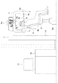
以下添付図面に従って本発明に係るX線CT装置の好ましい実施の形態について説明する。図1は、本発明に係るX線CT装置の全体構成を示す側面図であり、一部断面構成を示している。図2は図1の一部断面構成部を分かりやすいように拡大して示した部分拡大図である。
【0015】
このX線CT装置は、固定架台1、旋回アーム2、X線発生装置3、二次元X線検出装置4、第1の回転系6、第2の回転系5、椅子8、頭受け装置9から構成される。固定架台1は、支柱1aによって支持された逆L字型形状をしており、その先端部に第2の回転系5及び第1の回転系6を有する。旋回アーム2は、固定架台1の先端部に吊り下げられている。第1の回転系6は、旋回アーム2を吊り下げた状態で保持し、固定架台1の先端部の回転軸6aを回転中心として旋回アーム2を所定速度で回転させる。第2の回転系5は、第1の回転系6全体を回転軸5aを中心として所定の速度で回転させる。第1及び第1の回転系5,6の詳細については後述する。
【0016】
X線発生装置3は、X線を発生するものであり、旋回アーム2の一方の先端部に設けられる。X線発生装置3は、内部のX線発生源3aから照射されたX線3bをコーンビーム状に絞る絞り装置3cを備えている。二次元X線検出装置4は、X線発生装置3に対向して配置され、被検体を透過したX線量を2次元的に検出するものであり、旋回アーム2の他方の先端部に設けられている。すなわち、X線発生装置3と二次元X線検出装置4は、旋回アーム2によって互いに対向するように配置されている。旋回アーム2は、固定架台1の先端部を回転中心として第1の回転系6によって約405゜回転駆動されるようになっている。撮影する範囲は、360゜であるが、回転速度が一定になったところから撮影を開始するため、45°だけ回転範囲を広く取ってある。撮影開始後は、画像取りこみと同期してX線発生装置3がX線をパルス照射してX線による被曝を軽減させている。このタイミングは、第1の回転系6に内蔵された位置検出用エンコーダにより制御される。固定架台1の支柱1aの内部には撮影装置の制御系が組み込まれている。
【0017】
二次元X線検出装置4から採取された画像データは、画像処理装置12に送られる。画像処理装置12は、X線CT装置の設置された撮影室よりも離れた操作室内に設置される。画像処理装置12は、受信した画像データに演算処理を施し、二次元断層画像、CT画像または三次元立体画像を再構成し、それを画像表示装置13に表示する。
【0018】
旋回アーム2は、固定架台1に対して水平に回転可能な状態で支持される。この実施の形態の場合、旋回アーム2は、第2の回転系5及び第1の回転系6の上下二重構成になっている。これらの第1及び第1の回転系5,6は、軸受による回転支持機構と、サーボモーターと歯車などの組み合わせによって回転する駆動機構および位置検出機構、回転部のケーブル処理機構により構成される。第2の回転系5の回転中心5aは固定架台1に対して固定され、第1の回転系6の回転中心6aは旋回アーム2に対して固定されている。両者の回転中心5a,6aは一定の距離dだけ離された位置に置かれている。第1の回転系6の回転中心6aは、第2の回転系の駆動装置5bによって第2の回転系5の回転中心5aを回転軸として回転する。また、第2の回転系5の駆動装置5b(位置検出装置を含む)とケーブル処理機構(具体的構成は図示せず)は、固定架台1の内部に収納される。第1の回転系6の駆動装置6b(位置検出装置を含む)とケーブル処理機構6cは、第2の回転系5の上部側に収納される。これら二つの回転中心5aと回転中心6aとの間の距離dは、被検者7の歯列弓に概略一致する寸法、例えば直径70〜100mm程度である。第1の回転系6は、CT画像データを採取するために360度以上(約405°程度)回転する必要がある。これに対して第2の回転系5は、歯列弓に近似することを目的としているため、最大±120度程度まで回転できれば十分である。
【0019】
一方、被検者7は上下移動可能な椅子8に座している。椅子8の上下移動機構8aによって被検者7の検査部位7aは、撮影装置の撮影中心の高さに位置決め設定される。椅子8の背もたれ部8bは、角度調整が可能で、任意の角度で固定可能になっている。被検者7の前後方向の概略調整は、椅子の背もたれ部8bの角度調整と上下移動機構8aによる位置調整とを組み合わせて行う。頭受け装置9は、背もたれ部8bの後部に設けられ、椅子8に対して被検者7の頭部を所望の位置に固定するために、被検者7の座高の高さ、検査部位の位置に応じて上下・前後・左右に自在に位置調整可能に取り付けられている。被検者7の頭部は、術者によって所望の位置に移動された後、ヘッドバンド9b等で固定される。被検者7の検査部位7aの中心は、術者によって旋回アーム2の回転中心(前述の第1の回転系6の回転中心)6aに合わせられる。
【0020】
椅子8は、上下移動機構8aによって上下方向に移動するものであって、角度調整が可能である背もたれ部8bに頭受け装置9を取り付けれることができるものであれば、実施の形態のような専用の椅子でなくてもよい。すなわち、上下動ストロークなどの仕様を満足するものであれば、たとえば美容/理容で使用されるような椅子を利用することもできる。また、耳鼻科等で使用される治療用椅子でもよい。
【0021】
また、図1では、被検者7は固定架台1の地面に垂直な支柱1aに対して背を向けた状態を示したが、この実施の形態では撮影装置と椅子が分離されていることから、支柱1aに対する被検者の角度位置は、CT撮影が可能な回転範囲にあるならば、いずれの角度にあってもよい。例えば、被検者7を支柱1aに対向する向きに置いて撮影を行うこともできる。この場合、位置決め用の光学マーカーの投光器を支柱側に設置すれば、被検者7に対向する方向から光学マーカーを投影することができるので、位置決めしやすくなるという利点がある。あるいは装置が設置される撮影室のレイアウトに応じて、装置据付時に、支柱1aと椅子8の設置方向を自由に設定することもできる。
【0022】
図3は、この実施の形態に係るX線CT装置によって撮影する場合の位置決めの手順を示す図であり、図4はその一部拡大図を示す図である。1〜2本程度の歯牙に限定して局所のCT撮影を行う場合は、対象とする歯牙11aが位置する領域の中心7bと、X線CT装置の第1の回転系(旋回アーム)の回転中心6aとが一致するように、第2の回転系5を回転させる。ただし、第2の回転系5の回転中心5aと第1の回転系6の回転中心6aとの間の一定距離dを回転半径とする円10は、歯列弓11の形状・寸法に概略一致させたものであるため、歯牙の位置によっては、この円10と歯列弓11とは必ずしも一致しない場合がある。すなわち、被検者7を椅子8の左右中央に座らせただけでは、検査部位の中心7bと旋回アームの中心6aを一致させることはできない。
【0023】
撮影領域7aが、歯牙数本以上を含むのに十分な大きさがあれば、被検者7の中心位置を椅子の中心位置と一致させたときに、検査部位の中心7bと旋回アームの中心6aが多少ずれていても、対象とする検査部位が撮影範囲7aの中心近傍に含まれていれば十分目的を達成することができる。しかし、二次元X線検出装置4の検出部寸法の制限などにより対象部位が1〜2本程度の歯牙に限局された場合、あるいは大人と子供のように歯列弓11の形状・寸法が個人で異なり、この実施の形態に係るX線CT装置における第2の回転系5の回転中心5aと第1の回転系6の回転中心6bとの距離dを回転半径とする円10と、被検者の歯列弓11の形状・寸法との間に明らかな差異があって、その結果、対象とする検査部位である歯牙11aが撮影領域7aから外れる可能性がある場合には、検査部位の中心7bと旋回アームの回転中心6aの位置をできるだけ正確に合わせる必要がある。
【0024】
この実施の形態の場合は、椅子8の背もたれ部8bの角度調整と上下移動機構8aの上下位置調整とを適宜組み合わせて前後方向を概略調整し、検査部位11aの中心7bと第1の回転系6(旋回アーム2)の回転中心6aを概略一致させ、頭部を椅子8の頭受け9aに固定してから、頭受け装置9の前後左右動機構を使用して微調整することにより、検査部位11aの中心7bと第1の回転系6(旋回アーム2)の中心6aを完全に一致させることができる。
【0025】
上述の位置合わせ手順において、一般に被検者7が口腔を閉じた状態の体表面に投影された線状光学マーカーを基準とした位置合わせが行われるため、場合によっては対象とする歯牙の位置と撮影範囲の中心が完全に一致しているか外部から確認しにくいことがあり、実際に位置合わせのミスによる撮影の失敗が高い確率で起こっている。
【0026】
そこで、より確実な位置合わせ方法としては、上述のように光学マーカーで外部から一端位置合わせを行った後、撮影装置の旋回アーム2の方向を変えて直交二方向からのX線透視撮影を行うことによって、歯牙の位置を透視画像上で目視確認しながら、遠隔で被検者7の位置を微調整する方法がある。この場合は、被検者7の全体を動かして微調整するよりも、頭受け装置9を遠隔操作して被検者7の頭部の位置を直接微調整したほうが、より緻密で正確な位置調整が可能となる。また、安全性の観点からも、X線CT装置と被検者7である患者の接触を避けるため、あるいは外部から被検者7に加えられる外力と移動距離を軽減するために、被検者7の移動量はできるだけ小さくすることが望ましい。なお、上述の従来技術の項で説明した特開2000−139902号公報に記載された装置では、椅子または顎受け(チンレスト)の前後左右動のみによって、あるいは旋回アームの前後左右動と、椅子または顎受け(チンレスト)の前後左右動を組み合わせて被検者の位置決めを行うことを示唆している。これに対してこの実施の形態に係るX線CT装置の場合は、装置側で概略位置を合わせた後、椅子の頭受け装置に特定した微調整を行うことを特徴としている。この実施の形態によれば頭部の微調整範囲は高々±15mm程度であり、頭受け装置9の移動による被検者への負担は、被検者全体を動かして位置調整を行う場合(最大±50mm程度)に比較してはるかに少なく、また位置決め精度も向上し、位置決めに要する時間も短縮することができる。
【0027】
頭受け装置9の材質に関して、その周囲を旋回アーム2が回転してX線コーンビームを照射する都合上、X線コーンビーム3bが照射される部位の頭受け9aは、X線が吸収されて画像データ採取の障害とならないように、たとえばカーボンファイバーなどの、放射線透過性があり、しかも頭部を保持・固定するのに十分な強度を持った材質のものをすることが望ましい。
【0028】
頭受け装置9を使用する利点として、特に被検者7の後頭部が頭受け9aによって保持されるので、頭受け9aが、旋回アーム2の回転中にX線CT装置の本体と接触しないことが保証される構造になっていれば、頭部を頭受け9aに固定することによって、被検者7自身が目視確認できない領域(すなわち後頭部)の安全が確保されるという効果がある。
【0029】
この実施の形態では、被検者7の固定及び位置調整手段として、頭受け装置9のみを使用した例を提示したが、頭受け装置9に限定されず、従来装置で使用されている顎受け(チンレスト)とイヤーロッドの組み合わせ、あるいは被検者ごとの歯型に合わせて作成された咬合モデルを使用した固定具等を併用することが可能であり、これらが前後左右に微調整可能な構成になっていれば、これらの位置を微調整することで同様の位置決め機能を実現することができる。
【0030】
以上のように被検者7の位置が固定された状態で、X線発生装置3からX線コーンビーム3bを照射しながら旋回アーム2を回転させてCT撮影を行う。旋回アーム2の回転に応じて、X線発生装置3(図示せず)と対向して旋回アーム2の他端に取り付けられた二次元X線検出装置4は、旋回アーム2の回転角度ごとに応じて二次元X線検出装置4の位置から二次元X線検出装置41の位置に回転移動し、最終的に検査部位11aの周囲360°における透視画像データを採取する。採取された画像データは、画像処理装置12で演算処理され、二次元断層画像または三次元立体画像として再構成され、画像表示装置13に表示される。
【0031】
上述の撮影手順をまとめると以下の(1)〜(5)のような順番で実行されることになる。
(1)第2の回転系5を回転させて被検者7の撮影領域を概略位置決めする。
(2)椅子8の頭受け装置9を微調整して被検者7の位置を固定する。
(3)必要であれば直交二方向からのX線透視撮影を行って、歯牙の位置を透視画像上で目視確認しながら、遠隔で被検者の位置を微調整する。
(4)X線コーンビーム3bを照射しながら旋回アーム2を回転させてCT画像データを採取する。
(5)採取された画像データを画像処理装置12で演算処理し、二次元断層画像または三次元立体画像として再構成し、画像表示装置13に表示する。
【0032】
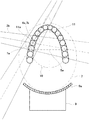
図5は、この実施の形態に係るX線CT装置によってパノラマ撮影する場合の動作を示す図であり、図6はその一部拡大図を示す図である。まず、被検者7の左右方向の中心を、第2の回転系5の回転中心5aに合わせる。椅子8の左右方向中心が、第2の回転系5の回転中心5aの直下にあるようにあらかじめ設置されていれば、頭受け装置9による微調整以外の被検者7の左右位置調整はほとんど必要ない。ただし、被検者7の歯列弓11が被検者7の左右中心に対してほぼ左右対称であることを前提とする。続いて、第2の回転系5の回転中心5aと第1の回転系6の回転中心6aとの距離dを回転半径とする円10と歯列弓11の形状・寸法とが概略一致するように、椅子8の背もたれ部8bの角度調整と上下移動機構8aの上下位置調整とを組み合わせて被検者7の前後方向位置を適宜調整し、その後頭部を頭受け装置9に固定してから、頭受け装置9の前後左右動機構によって微調整する。これによって、第1の回転系6の回転中心6aは円10上に位置するようになる。
【0033】
以上のように被検者7の位置が固定された状態で、第2の回転系5を回転させながら、第2の回転系5の回転角度に応じて、第1の回転系6により旋回アーム2を回転させ、歯列弓11の各歯牙に略直交する方向で、対向する歯列弓11の歯牙と干渉しない方向にX線コーンビーム3bを照射して歯列弓11を断層撮影する。第2の回転系5の回転中心5aと第1の回転系6の回転中心6aとの距離dを回転半径とする円10と実際の歯列弓11との形状・寸法の違いにより、歯牙の位置によってはX線発生源3aから被写体7までの距離の差が生じ、その結果二次元X線検出器4に投影された透視画像の拡大率や濃度に差が生じる。すなわち、歯牙11aを撮影する場合は、二次元X線検出器41から照射されたX線コンビーム3b1は、第1の回転系6の回転中心6a1及び歯牙11aの中心を通過するが、第1の回転系6の回転中心6a1と歯牙11aの中心との間には若干のずれがある。同様に、歯牙11bを撮影する場合は、二次元X線検出器42から照射されたX線コンビーム3b2は、第1の回転系6の回転中心6a2及び歯牙11bの中心を通過するが、第1の回転系6の回転中心6a2と歯牙11bの中心との間には若干のずれがある。歯牙11cを撮影する場合は、二次元X線検出器43から照射されたX線コンビーム3b3は、第1の回転系6の回転中心6a3及び歯牙11cの中心を通過するが、第1の回転系6の回転中心6a3と歯牙11cの中心との間には若干のずれがある。
【0034】
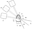
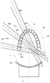
従って、第2の回転系5の回転角度に同期させて、画像演算処理においてこれらの若干のずれによる差分を補正してから、角度ごとの部分画像データを繋いで全角度にわたって連続した画像として再構成することにより、正確なパノラマ画像を得ることができる。図7は、第2の回転系の回転角度がそれぞれ異なる場合における第1の回転系6の回転中心と歯牙の中心との間のずれを示す図である。撮影対象となる歯牙が徐々に左端から右端に変化するに従って、第1の回転系6の回転中心6aは円10上を移動させる。これに伴ってX線コンビーム3b1〜3b6の照射角度も矢印70のように徐々に変化させる。これらのX線コンビーム3b1〜3b6に照射によって二次元X線検出器42には透視画像b1〜b6が撮影される。第2の回転系5の回転中心5aと第1の回転系6の回転中心6aとの距離dを回転半径とする円10と実際の歯列弓との形状・寸法の違いにより、歯牙の位置によってはX線発生源3aから被写体7までの距離の差が生じ、その結果二次元X線検出器4に投影された透視画像の拡大率や濃度に差が生じる。図8は、図7の各X線コンビーム3b1〜3b6のよって撮影された透視画像b1〜b6の拡大率補正前と補正後の状態を示す図である。図8(A)に示すように、拡大率補正前の各透視画像b1〜b6は、ほぼ同じ大きさの画像である。これに、それぞれの第1の回転系6の回転中心(円10上の点)と歯牙の中心との間のずれに応じてその拡大率k1〜k6を補正前の透視画像b1〜b6に乗算することによって、図8(B)のように透視画像b1〜b6の大きさを補正することができる。そして、大きさの補正された画像に基づいてパノラマ画像を再構築する。なお、図では、濃度については示していないが、濃度についても補正を加えることは言うまでもない。
【0035】
この補正処理は、従来例で前述した特開2000−139902号公報に記載された、被写体の歯列弓に対して照射されたX線コーンビームの中から、「オルソX線コーンビーム」と呼ばれる、歯列弓に略直交する方向のビームのみを抽出してパノラマ画像を得る画像演算処理に比較すれば処理すべき情報量が少なく、補正処理自体が容易なものであるため、画像演算処理速度にはほとんど影響しない。
【0036】
また、補正の基準となる歯列弓11の形状・寸法として、基本的に大人と子供用の二種類の標準サイズ歯列弓があれば、これを基準にして自動補正することができ、ソフトウェア上で使用する補正係数のテーブルも二種類のみとなるので、画像処理装置12に搭載すべきメモリー容量を低減でき、画像処理時間も短縮することができる。標準サイズ以外にも、個人ごとにカスタムメイドの歯列弓11の形状・寸法をソフトウェア上で作成できれば、より正確な補正が可能となることはいうまでもない。
【0037】
上述のパノラマ撮影手順をまとめると以下の(1)〜(6)のような順番で実行されることになる。
(1)椅子8の背もたれ8bの角度調整と上下移動機構8aの上下位置調整を組み合わせて、旋回アーム2(第1の回転系6)の回転中心6aの描く軌跡(円軌道)10と歯列弓11とが概略一致するように、被検者7の撮影領域を概略位置決めする。
(2)椅子8の頭受け装置9を微調整して被検者7の位置を固定する。
(3)第2の回転系5を回転させて、歯列弓11の端(奥歯)に照射開始位置を合わせ、同時に歯列弓11と略直交する方向で、対向する歯列弓11の歯牙と干渉しない方向に旋回アーム2の回転角度を合わせ、X線コーンビーム3bの照射を開始する。
(4)歯列弓11に沿って第2の回転系5を回転させながら、歯列弓11と略直交する方向で、対向する歯列弓11の各歯牙と干渉しない方向に旋回アーム2の回転角度を合わせ、X線コーンビーム3bを連続照射し、第2の回転系5の回転角度ごとに部分透視画像データを採取する。
(5)部分透視画像データ採取位置が歯列弓の他端(開始位置と逆の端の奥歯)に達したら撮影手順を終了する。
(6)第2の回転系5の回転角度ごとに採取した部分透視画像データの拡大率と濃度を、第2の回転系5の回転角度に同期させて画像処理装置12で補正した後、補正済み部分透視画像データを繋いで、全角度にわたって連続した歯列弓11のパノラマ画像を再構成し、画像表示装置13に表示する。
【0038】
図9は、本発明に係るX線CT装置の第2の回転系の回転部機構の変形例を示す図であり、図1のX線CT装置を上方側から見た図である。図10は、このX線CT装置によって描かれる回転半径の様子を示す図であり、図4に対応した拡大図である。図1におけるX線CT装置では、第2の回転系5の回転中心5aと第1の回転系6の回転中心6aとの距離(回転半径)dを固定のものとしていたが、図9のX線CT装置ではこの回転半径dを自在に可変できるような構成にし、歯列弓11に沿った複雑な形状の軌跡に沿って第1の回転系6の回転中心6aを追従させるようにした。直線駆動系は、第2の回転系5の上に搭載されたサーボモーターなどの駆動手段14aと、この駆動手段14aに駆動される送りねじやラック・ピニオンなどの直線駆動機構14bとから構成される。直線駆動系は、第1の回転系6の回転中心6aを矢印14cの方向に移動させて、第2の回転系5の回転中心5aと第1の回転系6の回転中心6aとの距離(回転半径)dを所望の位置に移動させる。このようにして、直線駆動系によって第1の回転系6の回転中心6aの位置が補正されることによって、第1の回転系6の回転中心6aの描く軌跡は、図10に示すように歯列弓11に沿った曲線10aのようになる。従って、前述のような第1の回転系6の回転中心6aと歯牙11の中心との間にはずれが生じなくなるので、これに伴って行っていた画像演算処理における補正処理は不要となり、演算時間を短縮することができる。
【0039】
直線駆動系が第1の回転系6の回転中心6aを移動させる範囲は、図4の歯列弓11の各歯牙の中心と回転半径10との間の距離に相当する差分であり、約±15mm程度で十分である。従来のパノラマ装置で必要であった旋回アームの前後左右移動機構(XYテーブル)の最大移動量(X、Yそれぞれ±50mm程度)よりも少ない移動量で位置調整することができる。また、移動量が少なければ、荷重支持・駆動装置を小型化することができ、装置の重量によるたわみなどを低減できる。したがって簡単な機構で精密な位置調整が可能となる。
【0040】
図9のX線CT装置によれば、被検者の歯列弓の形状・寸法によらず、装置側での正確な位置決めが容易になり、この回転半径調の整機構を遠隔操作可能な構成にすれば、頭受け装置9による微調整が不要となり、被検者7の負担を著しく軽減するとともに、椅子8の位置調整および被検者7を固定する機構を簡略化することができる。また、パノラマ撮影における透視画像の拡大率や濃度の差に対する画像補正も不要となるので、画像の演算処理時間を短縮することができる。
【0041】
このX線CT装置では撮影中に被検者を動かす必要がないことから、次ような撮影方法を実施することができる。すなわち、図10に示したように、歯列弓11全体をカバーするように2〜3本程度の歯牙を含むような局所領域7a〜7iについてX線CT撮影を連続して複数回(図10では9回)繰り返し実行することによって、複数個の局所撮影領域7aを組み合わせたCT画像データを採取すれば、小視野のX線検出装置を使った装置でも、歯列弓全体を表示するCT画像データを採取することができる。一般にX線検出装置4はその視野寸法に比例して高価なものとなるため、小視野のX線検出装置を使用すれば、撮影装置のコストを大幅に低減することができる。
【0042】
上述の局所領域の撮影手順をまとめると以下の(1)〜(7)のような順番で実行されることになる。
(1)旋回アーム2の回転中心6aの描く軌跡(歯列弓形状軌道)10aと被検者7の歯列弓11とが一致するように、被検者7の撮影領域を位置決めして固定する。
(2)歯列弓11の一端に位置する奥歯の中心、すなわち居所領域7aの中心に旋回アーム2の回転中心6aを合わせる。
(3)旋回アーム2を回転させながらX線コーンビーム3bを照射し、CT画像データを採取する。
(4)第2の回転系5を回転させ、採取されたCT画像データを居所領域7aと隣接し、かつその一部がオーバーラップするような次の居所領域7bの中心に、旋回アーム2の回転中心6aを合わせる。
(5)CT画像の採取及び位置合わせを歯列弓11に沿った居所領域7b〜7iについて繰り返す。
(6)歯列弓11の他端(開始位置とは逆の端の奥歯の中心、すなわち局所領域7iにおけるCT画像データ採取が終了したら撮影手順を終了する。
(7)採取されたCT画像データを画像処理装置12で演算処理し、歯列弓11の全体の画像を再構成し、画像表示装置13に表示する。
【0043】
この局所領域の撮影方法によれば、歯列弓11を含む顎部全体に対して一様にX線を照射する従来例と比較して、同じ領域に対して、より高分解能の画像を得ることができる。また、従来技術で説明したように、このデータから歯列弓に沿って歯列に直行する方向の透視画像データを抽出してパノラマ状の画像を再構成することもできる。同様にして任意断面の断層画像、立体画像を再構成することもできる。さらに、X線の照射部位を局所領域に制限することによって被検者7の被曝線量を低減することができる。従来の技術の項で説明した特開2000−139902号公報に記載された局所照射X線CT撮影装置による被曝量は、一般医療用CT撮影装置による被曝量の約1/30程度であることが知られている。従って、このような局所領域におけるCT撮影を連続して複数回行っても、たとえばCT画像データ採取の回数が上述の局所領域の撮影方法のように9回であれば、被曝量は一般医療用CT撮影装置による被曝量の約1/3以下の低いレベルに抑制される。また、実際には必ずしも歯列弓11全体を撮影する必要がない事例が多いので、被爆量はさらに低減される。一般医療用CT撮影装置では、歯列弓11の一部(たとえば右半分の歯列弓)のみを撮影しようとしても被曝量を低減することが困難だが、本実施例によれば、CT撮影の回数が少なくなるほど被曝量を低減することができる。
【0044】
この局所領域の撮影方法は、図3〜図6の撮影方法においても、局所CT撮影ごとに患者の位置決めを行って局所CT撮影を断続的に繰り返せば、同様の撮影が可能であることはいうまでもない。
【0045】
なお、この実施の形態に係るX線CT撮影装置は、特に歯科用に好適なものであるが、この技術は歯科用に限定されず、一般のX線CT撮影装置にも適用可能であることは言うまでもない。例えば、被写体がX線CT装置の撮影可能範囲より大きい場合などに、その一部に局所CT撮影を行う場合や、全体に対して連続局所CT撮影を行う場合、あるいは歯列弓の形状に相似した中空円筒状物体などの内面からのパノラマ画像を撮影する場合などにも適用可能である。
【0046】
図11は、この実施の形態に係るX線CT装置に使用される位置合わせ器具の概略構成を示す図である。この位置合わせ器具20は、被検者ごとの歯型に合わせて作成された咬合部15と、この咬合部15に接合部15aを介して接合されたフランジ16とから構成される。フランジ16は、咬合部15と平行な面上に固定された薄板からなる。被検者7が咬合部15を口腔内に装着したとき、フランジ16は接合部15aを介して被検者7の口腔外に露出する。フランジ16上には、第2の回転系5の回転中心5aを通る直交軸17,18にそれぞれ一致するようにラインマーク16a〜16cが刻印されている。また、各ラインマーク16a〜16cの両側近傍には、これらのラインマーク16a〜16cを中心として等間隔の目盛16dが刻まれている。この目盛16dは、CT撮影時において、対象とする撮影領域の中心と旋回アーム2の回転中心6aを一致させるために、被写体位置をシフトさせるときの移動量の目安となるものである。
【0047】
X線CT装置側には、フランジ16のラインマーク16a〜16cと一致する3方向から被検者7の顔面に対して光学マーカーを投影する投光器(図示せず)が取り付けてあり、これらの光軸の交点が第2の回転系5の回転中心5aを通るように位置決め設定する。そして、ラインマーク16a〜16cと光学マーカーとが一致するように、この位置合わせ器具20を装着した被検者7の位置を微調整すれば、口腔外から第2の回転系5の回転中心5aの位置を目視で確認することができる。従って、X線透視撮影を行わなくても、光学マーカーを基準とした位置合わせだけで正確な位置決めが可能となる。
【0048】
接合部15aとフランジ16の取り付け位置を変えることによって、咬合部15と第2の回転系5の回転中心5aとの位置関係を変えることができる。すなわち、旋回アーム2の回転中心6aの描く軌跡(円軌道)10と歯列弓11とが概略一致するように調整することが可能である。この調整には、円軌道10と歯列弓11の一致状態を確認するために、図11のような実物大の図をあらかじめ用意しておき、図と実物が一致することを確認しながら組み合わせる方法が便利である。また、この図は、3方向からの光学マーカー投光器の光軸の交点が、第2の回転系5の回転中心5aを通ることを確認する場合にも使用できる。なお、この位置合わせ器具20を図3〜図6に示したX線CT装置に適用する場合について説明したが、図9及び図10に示したX線CT装置についても、円軌道10の代わりに、歯列弓形状軌道10aを使用することでまったく同様に適用することができる。さらに、位置合わせ器具20をカメラなどで読み取り、画像処理を行って自動的に上述の位置合わせ処理を行うようにしてもよい。
【0049】
上述の位置合わせ器具20を用いた撮影手順をまとめると以下の(1)〜(4)のような順番で実行されることになる。
(1)位置合わせ器具20を被検者7に装着させ、被検者7の歯形モデルから咬合部15を作成する。
(2)旋回アーム2の回転中心6aの描く軌跡(円軌道)10又は歯列弓形状軌道10aと、歯列弓11とが概略一致するように接合部15aとフランジ16の取り付け位置を調整して、両者を接合・固定する。
(3)接合・固定した器具の咬合部15を被検者の歯列弓11に装着する。
(4)フランジ16のラインマーク16a〜16cを、装置の光学マーカーに合わせ、被検者を位置決めする。
【0050】
以上説明した実施の形態によれば、歯科用X線コーンビームCT撮影装置において、簡単な回転機構により、局所CT撮影時の位置合わせが容易に行えるとともに、位置決め機構を簡略化できる。またパノラマ撮影も簡単に行え、画像演算処理時間を大幅に短縮し、画像処理装置を簡略化できる。さらに、被検者を動かすことなく局所CT撮影とパノラマ撮影が行え、椅子の位置調整および被検者固定機構を簡略化することができる。また、パノラマ撮影における、撮影部位による透視画像の拡大率や濃度の差に対する画像補正も不要となる。小視野のX線CT装置でも、局所CT撮影を連続して複数回繰り返すことにより、歯列弓全体のCT画像データを高分解能で採取することができる。また、この画像データから歯列弓全体のパノラマ状の画像や、任意断面の断層画像、立体画像を再構成することもできる。
【0051】
なお、上述の実施の形態では、旋回アーム2は単体で構成される場合に着いて説明したが、旋回アームを二重構造とし、それらを相対的にスライドさせて、旋回アームの長さを半径方向に伸縮自在にし、X線発生装置3と二次元X線検出装置4との間の距離を調整できるようにしてもよい。
【0052】
なお、本発明の特徴として、請求項記載のもの以外に次のようなものが考えられる。
〔請求項1〕 被写体を挟んで対向するX線発生手段と二次元X線検出手段を搭載した旋回アームを回転させる機構を、歯列弓の形状に近似させた円周上で該旋回アーム回転軸の中心を回転可能とする機構上に搭載することにより、この機構を使って、CT撮影時にはX線局所照射部位の位置決めを行い、パノラマ撮影時には旋回アームの回転角度と組み合わせて撮影方向を調整することを特徴とするX線CT装置。
〔請求項2〕 被写体を挟んで対向するX線発生手段と二次元X線検出手段を搭載した旋回アームを回転させる機構を、該旋回アーム回転軸の中心を歯列弓の形状に近似させた円周上で回転可能とする機構上に搭載し、該旋回アームの回転角度と組み合わせて撮影方向を調整することでパノラマ撮影を行う場合に、該円周と歯列弓との距離の違いによって生じる、X線発生源からの被写体透視画像の拡大率の差を、画像演算処理によって補正することを特徴とする〔請求項1〕のX線CT装置。
〔請求項3〕 被写体を挟んで対向するX線発生手段と二次元X線検出手段を搭載した旋回アームを回転させる機構を、歯列弓の形状に近似させた円周上で該旋回アーム回転軸の中心を回転可能とする機構において、円周の直径寸法を可変とする機構を有することを特徴とする〔請求項1〕のX線CT装置。
〔請求項4〕 歯列弓に沿って局所CT撮影を連続して複数回繰り返すことにより、歯列弓全体のCT画像データを高分解能で採取し、この画像データから歯列弓全体のパノラマ状の画像や、任意断面の断層画像、立体画像を再構成することを特徴とするX線CT装置。
【0053】
【発明の効果】
本発明によれば、歯列弓を含む顎部全体や歯牙や顎関節の周囲などの局所にX線コーンビームを照射して、歯列、歯茎及びその周辺の組織や骨の状態を示すパノラマ画像を得る際の画像処理に要する時間を大幅に短縮化することができるという効果がある。
【図面の簡単な説明】
【図1】 本発明に係るX線CT装置の全体構成を示す側面図であり、一部断面構成を示している。
【図2】 図1の一部断面構成部を分かりやすいように拡大して示した部分拡大図である。
【図3】 図1の実施の形態に係るX線CT装置によって撮影する場合の位置決めの手順を示す図である。
【図4】 図3の一部拡大図である。
【図5】 図1の実施の形態に係るX線CT装置によってパノラマ撮影する場合の動作を示す図である。
【図6】 図5の一部拡大図である。
【図7】 第2の回転系の回転角度がそれぞれ異なる場合における第1の回転系6の回転中心と歯牙の中心との間のずれを示す図である。
【図8】 図7の各X線コンビームのよって撮影された透視画像の拡大率補正前と補正後の状態を示す図である。
【図9】 本発明に係るX線CT装置の第2の回転系の回転部機構の変形例を示す図であり、上方側から見た図である。
【図10】 図9のX線CT装置によって描かれる回転半径の様子を示す図である。
【図11】 この実施の形態に係るX線CT装置に使用される位置合わせ器具の概略構成を示す図である。
【符号の説明】
1…固定架台、1a…支柱、2…旋回アーム、3…X線発生装置、3a…X線発生源、3b…X線コーンビーム、3c…絞り装置、4…二次元X線検出装置、5…第2の回転系、5a…第2の回転系の回転中心、5b…第2の回転系の駆動装置、6…第1の回転系、6a…第1の回転系の回転中心、6b…第1の回転系の駆動装置、6c…ケーブル処理機構、7…被検者、7a…撮影領域、7b…検査部位の中心、8…椅子、8a…上下移動機構、8b…背もたれ部、9…頭受け装置、9a…頭受け、10…旋回アーム回転中心の描く軌跡(円軌道)、10a…旋回アーム回転中心の描く軌跡(歯列弓形状軌道)、11…歯列弓、11a…歯牙、12…画像処理装置、13…画像表示装置、14…直線駆動機構、15…位置合わせ器具の咬合部、15a…位置合わせ器具の接合部、16…位置合わせ器具のフランジ部、16a,16b,16c…ラインマーク、16d…目盛、17、18…直交軸、20…位置合わせ器具[0001]
BACKGROUND OF THE INVENTION
The present invention relates to an X-ray CT apparatus that irradiates a part of a subject with X-rays, processes a projection image thereof, and takes a tomographic image and the like, and particularly irradiates a part of a subject with an X-ray cone beam. The present invention relates to an X-ray CT apparatus suitable for imaging such as dentistry that can obtain an arbitrary CT tomographic screen and a panoramic image of the portion.
[0002]
[Prior art]
In dentistry, X-ray photography with film on the back of teeth, panoramic photography with X-ray tube and film rotating at the same time, Cefaro photography with a large distance between X-ray tube and film, etc. Is currently underway. Dental X-ray panoramic radiography is a continuous tomography of a tomographic image along the dentition, and a single image that develops a tomographic image showing the dentition and surrounding tissue and bones in a panoramic shape. To display.
[0003]
In a conventional panoramic imaging apparatus, a revolving arm equipped with an X-ray generator and a two-dimensional X-ray detection device facing each other with a subject interposed therebetween is supported by, for example, a front / rear / right / left moving unit and a rotating unit. It moves by drawing a complicated trajectory approximated to a row bow shape. As such a device, for example, there is a dental tomography apparatus described in Japanese Patent Laid-Open No. 06-78919.
[0004]
As a dental X-ray imaging apparatus, an X-ray CT apparatus capable of obtaining a cross-sectional image of a tooth other than panoramic imaging has been proposed. As such, for example, a medical X-ray tomography apparatus (first prior art) described in JP-A-09-122118 and X-ray CT imaging described in JP-A-11-318886 can be performed. There is a panoramic X-ray imaging apparatus (second prior art).
[0005]
As a known example of a general medical CT imaging apparatus using an X-ray cone beam, there is an apparatus (third prior art) described in, for example, JP-A-10-192267. According to this apparatus, a CT tomographic image of a subject can be obtained over a wide range, and therefore can be applied to a jaw part including a dental arch.
[0006]
On the other hand, as an X-ray CT imaging method and apparatus for irradiating only a part of a subject with an X-ray cone beam to obtain an arbitrary tomographic screen, stereoscopic image, or panoramic image of the part, There is a local irradiation X-ray CT imaging apparatus (fourth prior art) described in Japanese Patent Laid-Open No. 2000-139902. Especially in dental applications, this device reduces the subject's exposure by turning and irradiating the X-ray cone beam limited to the area around the teeth and temporomandibular joint, not the entire jaw including the dental arch. It is characterized by providing a reduced and high-resolution CT tomographic image or a three-dimensional stereoscopic image.
[0007]
According to the fourth prior art, only a beam called an ortho X-ray cone beam in a direction substantially orthogonal to the dental arch is extracted from the X-ray cone beams irradiated to the dental arch of the subject. Thus, an image calculation process is performed, whereby a panoramic image can be obtained. Therefore, panoramic photography equivalent to the conventional one can be performed with only a rotating mechanism of the swivel arm that is simpler than that of the conventional panoramic photographing apparatus, and since the mechanism is simple, the entire apparatus can be miniaturized. Furthermore, in the fourth prior art, as another embodiment, the width of the slit for limiting the X-ray irradiation width of the X-ray generator is changed in synchronization with the rotation of the swivel arm, so that the dental arch can be changed. There has also been proposed a method for forming a panoramic image by forming an ortho X-ray cone beam in a substantially orthogonal direction.
[0008]
Apart from these, also by the third prior art, a tomographic image in an arbitrary direction is obtained from CT data obtained by the X-ray cone beam irradiated to the entire jaw including the dental arch by image calculation processing. Alternatively, since it is a well-known fact that a three-dimensional image can be reconstructed, an equivalent panoramic image can be obtained. In addition, by subjecting the X-ray cone beam to a limited area and swirling the X-ray cone beam, the exposure dose of the subject can be reduced and the high-resolution CT can be obtained as in the fourth prior art. A tomographic image and a three-dimensional stereoscopic image can be provided.
[0009]
[Problems to be solved by the invention]
When panoramic shooting is performed using the fourth conventional technique, the shooting time is equal to or less (about 10 to 20 seconds) than the time required for shooting with a conventional panorama shooting apparatus. However, it is known that a long time (20 minutes to about 1 hour) is required for the image calculation processing until the image is displayed as an image on the image display device after photographing. The main cause of this is that the fourth prior art has three-dimensionally photographed the shape of the gums and the bones in the vicinity thereof, and based on the shape of the dentition, gums and the bones in the vicinity thereof based on the photographed tomographic images. The image processing is to create a desired panoramic image while making corrections. Even if a dedicated computer capable of high-speed arithmetic processing is used to perform such image arithmetic processing, the speed-up of the image arithmetic processing is naturally limited.
[0010]
The present invention has been made in view of the above-described points, and radiates an X-ray cone beam to the entire jaw portion including the dental arch and the periphery of the teeth and the temporomandibular joint, etc. An object of the present invention is to provide an X-ray CT apparatus capable of significantly reducing the time required for image processing when obtaining a panoramic image showing the state of surrounding tissues and bones.
[0011]
[Means for Solving the Problems]
An X-ray CT apparatus according to
[0012]
The X-ray CT apparatus according to
[0013]
The first rotation driving unit rotates a holding unit that holds the X-ray generation unit and the X-ray detection unit facing each other with the subject interposed therebetween. X-rays are emitted by the X-ray generation means and the X-ray detection means so as to rotate around a local portion near the rotation center of the first rotation driving means. When the second rotation driving unit integrally rotates the holding unit and the first rotation driving unit, the rotation center of the first rotation driving unit rotates on a predetermined circumference. Therefore, the second rotation drive means moves the rotation center of the first rotation drive means on the circumference approximating the shape of the dental arch, and at the time of CT imaging, the X-ray local irradiation site is positioned and panorama is obtained. At the time of imaging, the holding means is rotated so that the irradiation direction is substantially orthogonal to the dental arch while the center of rotation of the first rotational driving means is moved along a circle approximately approximating the shape of the dental arch. The angle, that is, the shooting direction can be adjusted as appropriate. Since it is possible to obtain an optimal panoramic image by such simple mechanical means, complicated image calculation processing is not required, and the time required for image processing when obtaining a panoramic image is greatly reduced. Can do. The difference in the distance from the X-ray source to the subject due to the difference between the shape of the circumference and the actual dental arch shape, resulting in a difference in the magnification of the fluoroscopic image depending on the position of the tooth. Synchronizing with the rotation angle of the rotation mechanism that moves on the circumference roughly approximated to the row bow, for each collected partial image data, by correcting this difference in the image calculation process and reconstructing the entire image, An accurate panoramic image can be obtained.
[0014]
DETAILED DESCRIPTION OF THE INVENTION
Preferred embodiments of an X-ray CT apparatus according to the present invention will be described below with reference to the accompanying drawings. FIG. 1 is a side view showing an overall configuration of an X-ray CT apparatus according to the present invention, and shows a partial cross-sectional configuration. FIG. 2 is a partially enlarged view showing the partial cross-sectional configuration part of FIG.
[0015]
This X-ray CT apparatus includes a fixed
[0016]
The
[0017]
Image data collected from the two-dimensional
[0018]
The
[0019]
On the other hand, the
[0020]
As long as the chair 8 is moved up and down by the
[0021]
Moreover, in FIG. 1, although the subject 7 showed the state which turned the back with respect to the support |
[0022]
FIG. 3 is a diagram showing a positioning procedure when imaging is performed by the X-ray CT apparatus according to this embodiment, and FIG. 4 is a partially enlarged view thereof. When performing local CT imaging limited to about one or two teeth, the
[0023]
If the
[0024]
In the case of this embodiment, the angle adjustment of the
[0025]
In the above-described alignment procedure, the alignment is generally performed based on the linear optical marker projected on the body surface of the subject 7 with the oral cavity closed, and in some cases, the position of the target tooth and It may be difficult to confirm from the outside whether the center of the shooting range is completely coincident, and in fact, a shooting failure due to a misalignment has a high probability.
[0026]
Therefore, as a more reliable alignment method, after one end alignment is performed from the outside with an optical marker as described above, X-ray fluoroscopic imaging from two orthogonal directions is performed by changing the direction of the
[0027]
Regarding the material of the
[0028]
As an advantage of using the
[0029]
In this embodiment, an example in which only the
[0030]
CT imaging is performed by rotating the
[0031]
When the above-described photographing procedures are summarized, they are executed in the following order (1) to (5).
(1) The imaging region of the subject 7 is roughly positioned by rotating the second
(2) The
(3) Perform X-ray fluoroscopic imaging from two orthogonal directions if necessary, and finely adjust the position of the subject remotely while visually confirming the position of the tooth on the fluoroscopic image.
(4) The
(5) The acquired image data is arithmetically processed by the
[0032]
FIG. 5 is a diagram showing an operation when panoramic imaging is performed by the X-ray CT apparatus according to this embodiment, and FIG. 6 is a partially enlarged view thereof. First, the center of the subject 7 in the left-right direction is aligned with the
[0033]
While the position of the subject 7 is fixed as described above, the swivel arm is rotated by the
[0034]
Accordingly, in synchronization with the rotation angle of the
[0035]
This correction processing is called “ortho X-ray cone beam” from among the X-ray cone beams irradiated to the dental arch of the subject described in Japanese Patent Laid-Open No. 2000-139902 described above in the conventional example. Compared with image calculation processing that extracts only a beam in a direction substantially orthogonal to the dental arch and obtains a panoramic image, the amount of information to be processed is small and the correction processing itself is easy. Has little effect.
[0036]
Moreover, if there are basically two types of standard size dental arches for adults and children as the shape and dimensions of the
[0037]
When the above panorama shooting procedure is summarized, it is executed in the following order (1) to (6).
(1) By combining the angle adjustment of the back 8b of the chair 8 and the vertical position adjustment of the
(2) The
(3) The
(4) While rotating the second
(5) When the partial fluoroscopic image data collection position reaches the other end of the dental arch (the back tooth at the end opposite to the start position), the imaging procedure is terminated.
(6) After the magnification rate and density of the partial fluoroscopic image data collected for each rotation angle of the
[0038]
FIG. 9 is a view showing a modification of the rotating unit mechanism of the second rotating system of the X-ray CT apparatus according to the present invention, and is a view of the X-ray CT apparatus of FIG. 1 as viewed from above. FIG. 10 is a diagram showing the state of the rotation radius drawn by this X-ray CT apparatus, and is an enlarged view corresponding to FIG. In the X-ray CT apparatus in FIG. 1, the distance (rotation radius) d between the
[0039]
The range in which the linear drive system moves the
[0040]
According to the X-ray CT apparatus of FIG. 9, accurate positioning on the apparatus side is facilitated regardless of the shape and dimensions of the subject's dental arch, and this rotational radius adjustment mechanism can be remotely operated. With this configuration, fine adjustment by the
[0041]
Since this X-ray CT apparatus does not require the subject to move during imaging, the following imaging method can be implemented. That is, as shown in FIG. 10, X-ray CT imaging is continuously performed a plurality of times for
[0042]
When the above-described local region imaging procedures are put together, they are executed in the following order (1) to (7).
(1) The imaging region of the subject 7 is positioned and fixed so that the trajectory (dental arch-shaped trajectory) 10a drawn by the
(2) The
(3) The
(4) The second
(5) The CT image acquisition and alignment are repeated for the
(6) The other end of the dental arch 11 (the center of the back tooth opposite to the start position, that is, when the CT image data collection in the
(7) The acquired CT image data is arithmetically processed by the
[0043]
According to this local region imaging method, a higher resolution image is obtained for the same region as compared with the conventional example in which the entire jaw including the
[0044]
This local region imaging method can also be performed in the imaging methods of FIGS. 3 to 6 if the patient is positioned for each local CT imaging and the local CT imaging is repeated intermittently. Not too long.
[0045]
The X-ray CT imaging apparatus according to this embodiment is particularly suitable for dentistry, but this technique is not limited to dental use and can be applied to a general X-ray CT imaging apparatus. Needless to say. For example, when the subject is larger than the imaging range of the X-ray CT apparatus, when performing local CT imaging on a part thereof, when performing continuous local CT imaging on the whole, or similar to the shape of the dental arch The present invention can also be applied to a case where a panoramic image is taken from the inner surface of a hollow cylindrical object.
[0046]
FIG. 11 is a diagram showing a schematic configuration of an alignment tool used in the X-ray CT apparatus according to this embodiment. The
[0047]
On the X-ray CT apparatus side, a projector (not shown) for projecting an optical marker onto the face of the subject 7 from three directions coinciding with the line marks 16a to 16c of the flange 16 is attached. Positioning is set so that the intersection of the axes passes through the
[0048]
By changing the attachment position of the joint 15a and the flange 16, the positional relationship between the
[0049]
When the photographing procedure using the above-described
(1) The
(2) The attachment positions of the joint 15a and the flange 16 are adjusted so that the trajectory (circular trajectory) 10 or the dental arch-shaped
(3) The
(4) The
[0050]
According to the embodiment described above, in the dental X-ray cone beam CT imaging apparatus, the positioning at the time of local CT imaging can be easily performed and the positioning mechanism can be simplified by a simple rotation mechanism. Further, panoramic photography can be easily performed, the image calculation processing time can be greatly shortened, and the image processing apparatus can be simplified. Furthermore, local CT imaging and panoramic imaging can be performed without moving the subject, and the position adjustment of the chair and the subject fixing mechanism can be simplified. In panoramic photography, it is not necessary to perform image correction with respect to a difference in magnification or density of a fluoroscopic image depending on a photographing part. Even in a small-field X-ray CT apparatus, CT image data of the entire dental arch can be collected with high resolution by repeating local CT imaging a plurality of times. Further, a panoramic image of the entire dental arch, a tomographic image of an arbitrary cross section, and a stereoscopic image can be reconstructed from this image data.
[0051]
In the above-described embodiment, the
[0052]
As features of the present invention, the following may be considered in addition to those described in the claims.
[Claim 1] A mechanism for rotating a swivel arm equipped with an X-ray generation unit and a two-dimensional X-ray detection unit facing each other with a subject interposed therebetween is rotated on a circumference approximating the shape of a dental arch. By mounting on a mechanism that allows the center of the shaft to rotate, this mechanism is used to position the local X-ray irradiation site during CT imaging, and to adjust the imaging direction in combination with the rotation angle of the swivel arm during panoramic imaging X-ray CT apparatus characterized by performing.
[Claim 2] A mechanism for rotating a swivel arm equipped with an X-ray generation means and a two-dimensional X-ray detection means facing each other with a subject interposed therebetween is made to approximate the center of the swivel arm rotation axis to the shape of a dental arch. When mounted on a mechanism that can rotate on the circumference and panoramic photography is performed by adjusting the photography direction in combination with the rotation angle of the swivel arm, the difference in distance between the circumference and the dental arch The X-ray CT apparatus according to
[Claim 3] A mechanism for rotating a swivel arm equipped with an X-ray generation unit and a two-dimensional X-ray detection unit facing each other with a subject interposed therebetween is rotated on a circumference approximating the shape of a dental arch. The X-ray CT apparatus according to
[Claim 4] CT image data of the entire dental arch is collected with high resolution by repeating local CT imaging a plurality of times along the dental arch, and a panoramic shape of the entire dental arch is obtained from this image data. An X-ray CT apparatus that reconstructs a tomographic image, an arbitrary cross-sectional image, and a stereoscopic image.
[0053]
【The invention's effect】
According to the present invention, a panorama showing the state of the dentition, gums and surrounding tissues and bones by irradiating the entire jaw including the dental arch, the local area such as the periphery of the teeth and temporomandibular joint, and the like. There is an effect that the time required for image processing when obtaining an image can be greatly shortened.
[Brief description of the drawings]
FIG. 1 is a side view showing an overall configuration of an X-ray CT apparatus according to the present invention, showing a partial cross-sectional configuration.
FIG. 2 is a partially enlarged view showing a partial cross-sectional configuration part of FIG.
FIG. 3 is a diagram showing a positioning procedure when imaging is performed by the X-ray CT apparatus according to the embodiment of FIG. 1;
FIG. 4 is a partially enlarged view of FIG. 3;
FIG. 5 is a diagram showing an operation when panoramic imaging is performed by the X-ray CT apparatus according to the embodiment of FIG. 1;
6 is a partially enlarged view of FIG. 5;
FIG. 7 is a diagram showing a shift between the rotation center of the
8 is a diagram showing a state before and after correction of the enlargement ratio of a fluoroscopic image photographed by each X-ray conbeam of FIG. 7. FIG.
FIG. 9 is a view showing a modification of the rotation unit mechanism of the second rotation system of the X-ray CT apparatus according to the present invention, as viewed from above.
FIG. 10 is a diagram showing a state of a turning radius drawn by the X-ray CT apparatus of FIG. 9;
FIG. 11 is a diagram showing a schematic configuration of an alignment tool used in the X-ray CT apparatus according to this embodiment.
[Explanation of symbols]
DESCRIPTION OF
Claims (3)
このX線発生手段に対向して配置され、被検体を透過した前記X線量を2次元的に検出するX線検出手段と、
前記X線発生手段と前記X線検出手段との間に前記被検体が位置するように前記X線発生手段及び前記X線検出手段を保持する保持手段と、
この保持手段を前記被検体の周囲に沿って回転駆動する第1の回転駆動手段と、
この第1の回転駆動手段の回転中心に平行でその回転中心が異なる位置関係となるように配置され前記第1の回転駆動手段を一体的に回転駆動する第2の回転駆動手段と、
前記第1の回転駆動手段のみによって得られた複数の角度方向の透視画像から前記被検体の二次元断層像又は三次元立体像(コーンビームCT像)を再構成する撮影モードと、前記第1の回転駆動手段及び第2の回転駆動手段によって得られた複数の角度方向の透視画像から前記被検体のパノラマ画像を再構成する撮影モードの何れかを設定する設定手段と、
この設定手段によって設定された撮影モードにより前記被検体のコーンビームCT像又はパノラマ画像の何れかの画像を再構成する画像処理手段と、
この画像処理手段によって再構成された画像を表示する画像表示手段とを備えたX線CT装置において、
前記画像処理手段は、前記第1の回転駆動手段の回転中心と前記被検体の撮影部位の中心との位置ずれによって前記複数の角度方向毎に生じる前記被検体の透視画像の拡大率及び濃度の差に基づいて前記透視画像の拡大率及び濃度を補正する補正処理手段を含むことを特徴とするX線CT装置。X-ray generation means for generating X-rays;
X-ray detection means that is arranged opposite to the X-ray generation means and detects the X-ray dose transmitted through the subject two-dimensionally;
Holding means for holding the X-ray generation means and the X-ray detection means so that the subject is positioned between the X-ray generation means and the X-ray detection means;
A first rotation driving means for rotating the holding means along the periphery of the subject;
A second rotation driving means arranged so as to be in a positional relationship parallel to the rotation center of the first rotation driving means and having different rotation centers; and integrally rotating the first rotation driving means;
An imaging mode for reconstructing a two-dimensional tomographic image or a three-dimensional stereoscopic image (cone beam CT image) of the subject from a plurality of fluoroscopic images obtained by only the first rotation driving means; Setting means for setting any one of imaging modes for reconstructing a panoramic image of the subject from a plurality of angular perspective images obtained by the rotation driving means and the second rotation driving means;
Image processing means for reconstructing either a cone beam CT image or a panoramic image of the subject according to the imaging mode set by the setting means;
In an X-ray CT apparatus comprising image display means for displaying an image reconstructed by the image processing means,
The image processing unit is configured to detect a magnification and a density of a fluoroscopic image of the subject generated in each of the plurality of angular directions due to a positional deviation between the rotation center of the first rotation driving unit and the center of the imaging region of the subject An X-ray CT apparatus comprising correction processing means for correcting the magnification and density of the fluoroscopic image based on the difference.
Priority Applications (5)
| Application Number | Priority Date | Filing Date | Title |
|---|---|---|---|
| JP2002103124A JP4149189B2 (en) | 2002-04-04 | 2002-04-04 | X-ray CT system |
| CNA038058200A CN1642483A (en) | 2002-04-04 | 2003-04-03 | Tomograph |
| EP03745901A EP1491145A4 (en) | 2002-04-04 | 2003-04-03 | Tomograph |
| PCT/JP2003/004286 WO2003084406A1 (en) | 2002-04-04 | 2003-04-03 | Tomograph |
| US10/509,915 US20050117693A1 (en) | 2002-04-04 | 2003-04-03 | Tomograph |
Applications Claiming Priority (1)
| Application Number | Priority Date | Filing Date | Title |
|---|---|---|---|
| JP2002103124A JP4149189B2 (en) | 2002-04-04 | 2002-04-04 | X-ray CT system |
Publications (3)
| Publication Number | Publication Date |
|---|---|
| JP2003290220A JP2003290220A (en) | 2003-10-14 |
| JP2003290220A5 JP2003290220A5 (en) | 2005-09-15 |
| JP4149189B2 true JP4149189B2 (en) | 2008-09-10 |
Family
ID=28786289
Family Applications (1)
| Application Number | Title | Priority Date | Filing Date |
|---|---|---|---|
| JP2002103124A Expired - Fee Related JP4149189B2 (en) | 2002-04-04 | 2002-04-04 | X-ray CT system |
Country Status (5)
| Country | Link |
|---|---|
| US (1) | US20050117693A1 (en) |
| EP (1) | EP1491145A4 (en) |
| JP (1) | JP4149189B2 (en) |
| CN (1) | CN1642483A (en) |
| WO (1) | WO2003084406A1 (en) |
Families Citing this family (77)
| Publication number | Priority date | Publication date | Assignee | Title |
|---|---|---|---|---|
| US7099431B2 (en) * | 2003-06-09 | 2006-08-29 | Canon Kabushiki Kaisha | Radiation imaging apparatus |
| DE102004050172B4 (en) * | 2004-08-20 | 2010-09-02 | "Stiftung Caesar" (Center Of Advanced European Studies And Research) | 3D reconstruction with oblique geometry |
| FI118624B (en) * | 2005-03-14 | 2008-01-31 | Planmeca Oy | Orthodontic computed tomography imaging |
| JP4307406B2 (en) * | 2005-04-22 | 2009-08-05 | 株式会社モリタ製作所 | Medical X-ray imaging apparatus and X-ray detector used therefor |
| US7991242B2 (en) | 2005-05-11 | 2011-08-02 | Optosecurity Inc. | Apparatus, method and system for screening receptacles and persons, having image distortion correction functionality |
| CA2608119A1 (en) | 2005-05-11 | 2006-11-16 | Optosecurity Inc. | Method and system for screening luggage items, cargo containers or persons |
| JP4536596B2 (en) * | 2005-05-26 | 2010-09-01 | パナソニック株式会社 | Panoramic X-ray equipment |
| KR100794563B1 (en) * | 2005-08-08 | 2008-01-17 | 주식회사바텍 | The combined panoramic and computed tomography photographing apparatus |
| KR100707796B1 (en) * | 2005-08-08 | 2007-04-13 | 주식회사바텍 | The combined panoramic and computed tomography photographing apparatus |
| JP4758747B2 (en) * | 2005-12-09 | 2011-08-31 | 株式会社日立メディコ | X-ray measuring apparatus, X-ray measuring method and X-ray measuring program |
| US8366442B2 (en) * | 2006-02-15 | 2013-02-05 | Bankruptcy Estate Of Voxelogix Corporation | Dental apparatus for radiographic and non-radiographic imaging |
| KR100938486B1 (en) | 2006-05-02 | 2010-01-25 | 주식회사 레이 | Complex Imaging System for Dental |
| DE102006021051A1 (en) * | 2006-05-05 | 2007-11-15 | Siemens Ag | Medical image e.g. computer tomography image, generating method for use during surgery, involves producing volume image data set based on reconstruction volume, and generating medical images with respect to section plane of image data set |
| US7899232B2 (en) | 2006-05-11 | 2011-03-01 | Optosecurity Inc. | Method and apparatus for providing threat image projection (TIP) in a luggage screening system, and luggage screening system implementing same |
| JP5075352B2 (en) * | 2006-05-17 | 2012-11-21 | 朝日レントゲン工業株式会社 | Cephalo X-ray system |
| US8494210B2 (en) | 2007-03-30 | 2013-07-23 | Optosecurity Inc. | User interface for use in security screening providing image enhancement capabilities and apparatus for implementing same |
| WO2008035828A1 (en) * | 2006-09-22 | 2008-03-27 | Ray Co., Ltd. | Dental complex imaging system |
| US7835811B2 (en) | 2006-10-07 | 2010-11-16 | Voxelogix Corporation | Surgical guides and methods for positioning artificial teeth and dental implants |
| FI20065793L (en) * | 2006-12-12 | 2008-06-13 | Palodex Group Oy | X-ray photography apparatus and procedure for photographing the mandibular part |
| KR100861409B1 (en) | 2006-12-13 | 2008-10-08 | 주식회사바텍 | Panoramic x-ray photographing apparatus and method for photographing using the same |
| AU2007343330B2 (en) * | 2007-01-10 | 2013-08-01 | Nobel Biocare Services Ag | Method and system for dental planning and production |
| JP2008229322A (en) | 2007-02-22 | 2008-10-02 | Morita Mfg Co Ltd | Image processing method, image displaying method, image processing program, storage medium, image processor, and x-ray imaging device |
| JP5046238B2 (en) * | 2007-02-27 | 2012-10-10 | 株式会社モリタ製作所 | X-ray CT imaging image display method, X-ray CT image display device, X-ray CT imaging device |
| FI125008B (en) * | 2007-03-19 | 2015-04-30 | Planmeca Oy | A panoramic X-ray machine and setting a reflective layer for panoramic imaging |
| KR100907821B1 (en) * | 2007-05-29 | 2009-07-14 | 차영진 | Composite image taking device for dental medical diagnosis |
| AT506257B1 (en) * | 2007-09-21 | 2012-04-15 | Weinlaender Michael Dr | DEVICE FOR PRODUCING PHOTOGRAPHIC PHOTOGRAPHIC RECORDINGS |
| KR100917679B1 (en) * | 2008-01-15 | 2009-09-21 | 주식회사바텍 | Multy layer panorama imaging apparatus and imaging method thereof |
| DE102008008733A1 (en) * | 2008-02-12 | 2009-08-13 | Sirona Dental Systems Gmbh | Method for creating a tomogram |
| JP4716442B2 (en) * | 2008-04-15 | 2011-07-06 | 株式会社吉田製作所 | X-ray imaging method and apparatus |
| FR2938182B1 (en) | 2008-08-22 | 2010-11-19 | Trophy | DENTAL RADIOLOGY APPARATUS AND METHOD OF USE THEREOF |
| JP5231959B2 (en) * | 2008-12-01 | 2013-07-10 | 株式会社吉田製作所 | X-ray CT imaging apparatus and signal processing method thereof |
| EP2229914B1 (en) | 2009-03-20 | 2018-05-30 | Nobel Biocare Services AG | System and method for aligning virtual models |
| JP5204899B2 (en) * | 2009-06-25 | 2013-06-05 | 株式会社吉田製作所 | X-ray equipment |
| EP2722818B1 (en) * | 2009-09-04 | 2019-11-06 | Medicim NV | Method for digitizing dento-maxillofacial objects |
| US8348669B1 (en) | 2009-11-04 | 2013-01-08 | Bankruptcy Estate Of Voxelogix Corporation | Surgical template and method for positioning dental casts and dental implants |
| FI125450B (en) * | 2009-11-25 | 2015-10-15 | Planmeca Oy | Dental computed tomography equipment |
| FI123899B (en) * | 2009-11-25 | 2013-12-13 | Planmeca Oy | Dental computed tomography equipment |
| CN101716083B (en) * | 2009-12-25 | 2011-05-11 | 齐军 | General positioning chair for cephalometry |
| FI126561B (en) | 2010-02-23 | 2017-02-15 | Planmeca Oy | Patient support for dental x-ray equipment |
| JP5878121B2 (en) * | 2010-07-13 | 2016-03-08 | 株式会社テレシステムズ | X-ray tomography system |
| CN103327897B (en) * | 2011-01-18 | 2015-08-26 | 株式会社日立医疗器械 | Moving X-ray inspection apparatus |
| CA2849398C (en) | 2011-09-07 | 2020-12-29 | Rapiscan Systems, Inc. | X-ray inspection system that integrates manifest data with imaging/detection processing |
| CN102940504B (en) * | 2012-02-22 | 2017-05-03 | 中国医学科学院整形外科医院 | Zygomatic arch, skull base, top chin and submandibular top cephalometric positioning and shooting chair |
| CN102626319B (en) * | 2012-04-26 | 2014-06-04 | 上海优益基医疗器械有限公司 | Automatic adjusting system and method for patient ray irradiation position of CBCT |
| CN102755173A (en) * | 2012-07-06 | 2012-10-31 | 北京工业大学 | Digitization panorama dental X line imager |
| CN102783967B (en) * | 2012-08-23 | 2014-06-04 | 汕头市超声仪器研究所有限公司 | Breast CT (Computed Tomography) apparatus |
| CN104287771A (en) * | 2013-07-15 | 2015-01-21 | 南京普爱射线影像设备有限公司 | Dental department CT three-dimensional imaging synchronous control method and device based on embedded software |
| CN105828719B (en) * | 2013-08-20 | 2019-01-15 | 韩国威泰有限公司 | X-ray imaging device |
| DE102013216858A1 (en) * | 2013-08-23 | 2015-02-26 | Siemens Aktiengesellschaft | A method for displaying an object imaged in a volume data set on a screen |
| CN103462631B (en) * | 2013-09-22 | 2015-10-21 | 江苏美伦影像系统有限公司 | Multi-angle cone-beam CT imaging instrument |
| CN103690182B (en) * | 2013-12-24 | 2015-09-30 | 杭州美诺瓦医疗科技有限公司 | Digital oral cavity panoramic X-ray imaging device |
| ES2941715T3 (en) * | 2014-05-22 | 2023-05-25 | Carestream Dental Tech Topco Ltd | Procedure for 3D cephalometric analysis |
| WO2016018002A1 (en) * | 2014-07-28 | 2016-02-04 | 주식회사바텍 | X-ray imaging device and x-ray imaging method |
| CN104524699A (en) * | 2014-12-19 | 2015-04-22 | 左太阳 | Novel improved positioning device for head tumor radiotherapy |
| JP1540372S (en) * | 2015-02-25 | 2018-12-10 | ||
| JP1540371S (en) * | 2015-02-25 | 2018-12-10 | ||
| CN105982689A (en) * | 2015-02-28 | 2016-10-05 | 朱全祥 | CT imaging system |
| CN104887262B (en) * | 2015-06-29 | 2017-10-20 | 青岛大学附属医院 | Digitalized learning course machine |
| ITUB20151800A1 (en) * | 2015-07-02 | 2017-01-02 | Cefla S C | METHOD AND APPARATUS FOR THE ACQUISITION OF PANORAMIC RADIOGRAPHIES AND VOLUMETRIC RADIOGRAPHIES CBCT |
| KR101725642B1 (en) * | 2015-07-17 | 2017-04-11 | 오스템임플란트 주식회사 | X-ray photographing apparatus and method |
| WO2017146930A1 (en) | 2016-02-22 | 2017-08-31 | Rapiscan Systems, Inc. | Systems and methods for detecting threats and contraband in cargo |
| WO2018086049A1 (en) * | 2016-11-11 | 2018-05-17 | 江苏美伦影像系统有限公司 | Multi-source x-ray oral ct machine |
| JP6666283B2 (en) * | 2017-02-23 | 2020-03-13 | 株式会社モリタ製作所 | X-ray tomography apparatus and X-ray tomography method |
| FI127574B (en) * | 2017-03-17 | 2018-09-14 | Planmeca Oy | X-ray imaging apparatus and patient support |
| FI127695B (en) * | 2017-03-17 | 2018-12-14 | Planmeca Oy | X-ray apparatus and patient support arrangement |
| CN107080554B (en) * | 2017-05-17 | 2020-06-02 | 杭州口腔医院集团有限公司 | Temporomandibular joint measuring method and dental lamina preparation method |
| US20180342043A1 (en) * | 2017-05-23 | 2018-11-29 | Nokia Technologies Oy | Auto Scene Adjustments For Multi Camera Virtual Reality Streaming |
| JP6837400B2 (en) * | 2017-08-23 | 2021-03-03 | 株式会社モリタ製作所 | X-ray imaging device and X-ray imaging method |
| CN107616808A (en) * | 2017-09-28 | 2018-01-23 | 广州柿子信息技术有限公司 | Automate oral cavity conical beam CT machine |
| CN107753053A (en) * | 2017-10-31 | 2018-03-06 | 江苏美伦影像系统有限公司 | A kind of pencil-beam oral cavity fault image closed loop acquisition system based on angle feed-back |
| EP3733074A4 (en) * | 2017-12-28 | 2021-08-25 | J. Morita Manufacturing Corporation | X-ray ct imaging device |
| US10898147B2 (en) * | 2018-04-13 | 2021-01-26 | Palodex Group Oy | Adjustable lower shelf on an X-ray unit |
| JP6837452B2 (en) * | 2018-04-27 | 2021-03-03 | 株式会社モリタ製作所 | Control method of X-ray CT imaging device and X-ray CT imaging device |
| CN113069141B (en) * | 2021-03-31 | 2023-03-31 | 有方(合肥)医疗科技有限公司 | Method and system for shooting oral panoramic film, electronic equipment and readable storage medium |
| CN114513605B (en) * | 2022-01-25 | 2024-03-05 | 重庆医药高等专科学校 | Big data storage system for image shooting |
| CN117414144A (en) * | 2022-07-04 | 2024-01-19 | 合肥美亚光电技术股份有限公司 | Cone beam CT apparatus control method, cone beam CT apparatus, and medium |
| CN115005860B (en) * | 2022-08-03 | 2022-11-15 | 有方(合肥)医疗科技有限公司 | Method and device for reducing oral and maxillofacial CBCT imaging motion artifacts |
Family Cites Families (8)
| Publication number | Priority date | Publication date | Assignee | Title |
|---|---|---|---|---|
| JPS58175546A (en) * | 1982-04-07 | 1983-10-14 | 株式会社モリタ製作所 | Dental x-ray diagnostic apparatus |
| FI73091C (en) * | 1985-05-31 | 1987-08-10 | Planmeca Oy | Panoramic tomography X-ray device for special dental photography. |
| DE3542333A1 (en) * | 1985-11-29 | 1987-06-04 | Siemens Ag | X-RAY EXAMINATION DEVICE |
| JPH0715524Y2 (en) * | 1988-09-13 | 1995-04-12 | 株式会社モリタ製作所 | Dental panoramic cephalography system |
| FI87135C (en) * | 1989-09-14 | 1992-12-10 | Instrumentarium Oy | ANORDING FOR THE COMMITTEE OF THE EUROPEAN PARLIAMENT AND OF THE COUNCIL |
| US5841148A (en) * | 1996-02-02 | 1998-11-24 | Fuji Photo Film Co., Ltd. | Image processing apparatus |
| FR2758710B1 (en) * | 1997-01-27 | 1999-09-24 | Catalin Stoichita | ROTATION MECHANISM FOR DENTAL PANORAMICS |
| FI103177B1 (en) * | 1997-10-02 | 1999-05-14 | Planmeca Oy | X-ray imaging device for the skull area |
-
2002
- 2002-04-04 JP JP2002103124A patent/JP4149189B2/en not_active Expired - Fee Related
-
2003
- 2003-04-03 CN CNA038058200A patent/CN1642483A/en active Pending
- 2003-04-03 WO PCT/JP2003/004286 patent/WO2003084406A1/en not_active Application Discontinuation
- 2003-04-03 US US10/509,915 patent/US20050117693A1/en not_active Abandoned
- 2003-04-03 EP EP03745901A patent/EP1491145A4/en not_active Withdrawn
Also Published As
| Publication number | Publication date |
|---|---|
| US20050117693A1 (en) | 2005-06-02 |
| EP1491145A4 (en) | 2006-04-12 |
| CN1642483A (en) | 2005-07-20 |
| EP1491145A1 (en) | 2004-12-29 |
| WO2003084406A1 (en) | 2003-10-16 |
| JP2003290220A (en) | 2003-10-14 |
Similar Documents
| Publication | Publication Date | Title |
|---|---|---|
| JP4149189B2 (en) | X-ray CT system | |
| JP3743594B2 (en) | CT imaging device | |
| US6493415B1 (en) | X-ray computed tomography method and apparatus | |
| JP3926334B2 (en) | X-ray CT imaging system | |
| JP3919048B2 (en) | Local irradiation X-ray CT imaging system | |
| JP5555231B2 (en) | Method and X-ray apparatus for generating a three-dimensional X-ray image of a tooth | |
| JP5539729B2 (en) | X-ray CT imaging system | |
| US8538110B2 (en) | Medical X-ray CT imaging apparatus, medical X-ray CT image display device, and medical X-ray CT image display method | |
| KR20070017670A (en) | The combined panoramic and computed tomography photographing apparatus | |
| JP2002315746A (en) | X-ray imaging position setting means for subject and radiograph with the same | |
| EP2708188B1 (en) | X-ray imaging apparatus | |
| KR20160001706A (en) | X-ray imaging unit for a medical imaging | |
| JP2002219127A (en) | Panoramic x-ray ct photographing device | |
| KR20120114267A (en) | Dental x-ray apparatus providing a cephalometric image and related method | |
| JPH04312451A (en) | Tomography method and apparatus | |
| US10441227B2 (en) | Cephalostat | |
| JP3966425B2 (en) | Local irradiation X-ray CT imaging system | |
| US5012501A (en) | Apparatus for producing panoramic x-ray image projections | |
| EP2594201A1 (en) | Panoramic dental X-ray unit | |
| WO2007078027A1 (en) | Method for photographing using x-ray photographing apparatus | |
| JP2008161234A (en) | X-ray tomographic apparatus | |
| JP5746132B2 (en) | Medical X-ray equipment | |
| KR20190090351A (en) | X-ray imaging unit for a x-ray imaging | |
| JP2004357912A (en) | X-ray tomograph | |
| CN111616731A (en) | System and method for realizing intraoral tomography scanning |
Legal Events
| Date | Code | Title | Description |
|---|---|---|---|
| A521 | Request for written amendment filed |
Free format text: JAPANESE INTERMEDIATE CODE: A523 Effective date: 20050324 |
|
| A621 | Written request for application examination |
Free format text: JAPANESE INTERMEDIATE CODE: A621 Effective date: 20050324 |
|
| RD04 | Notification of resignation of power of attorney |
Free format text: JAPANESE INTERMEDIATE CODE: A7424 Effective date: 20080221 |
|
| A131 | Notification of reasons for refusal |
Free format text: JAPANESE INTERMEDIATE CODE: A131 Effective date: 20080226 |
|
| A521 | Request for written amendment filed |
Free format text: JAPANESE INTERMEDIATE CODE: A523 Effective date: 20080402 |
|
| TRDD | Decision of grant or rejection written | ||
| A01 | Written decision to grant a patent or to grant a registration (utility model) |
Free format text: JAPANESE INTERMEDIATE CODE: A01 Effective date: 20080624 |
|
| A01 | Written decision to grant a patent or to grant a registration (utility model) |
Free format text: JAPANESE INTERMEDIATE CODE: A01 |
|
| A61 | First payment of annual fees (during grant procedure) |
Free format text: JAPANESE INTERMEDIATE CODE: A61 Effective date: 20080625 |
|
| FPAY | Renewal fee payment (event date is renewal date of database) |
Free format text: PAYMENT UNTIL: 20110704 Year of fee payment: 3 |
|
| R150 | Certificate of patent or registration of utility model |
Free format text: JAPANESE INTERMEDIATE CODE: R150 |
|
| LAPS | Cancellation because of no payment of annual fees |