JP4148251B2 - Imaging device and display device - Google Patents
Imaging device and display device Download PDFInfo
- Publication number
- JP4148251B2 JP4148251B2 JP2005254056A JP2005254056A JP4148251B2 JP 4148251 B2 JP4148251 B2 JP 4148251B2 JP 2005254056 A JP2005254056 A JP 2005254056A JP 2005254056 A JP2005254056 A JP 2005254056A JP 4148251 B2 JP4148251 B2 JP 4148251B2
- Authority
- JP
- Japan
- Prior art keywords
- imaging
- video signal
- image
- panoramic
- imaging means
- Prior art date
- Legal status (The legal status is an assumption and is not a legal conclusion. Google has not performed a legal analysis and makes no representation as to the accuracy of the status listed.)
- Expired - Fee Related
Links
Images


Description
本発明は、例えばコンピュータネットワークを利用して遠隔地からの観視を行う際に使用して好適な撮像装置及び表示装置に関するものである。 The present invention relates to an imaging device and a display device that are suitable for use when viewing from a remote location using, for example, a computer network.
事象の観察や監視、案内等の目的で、遠隔地からの画像を例えばコンピュータネットワーク(インターネット)を利用して観視を行うことが考えられている。そのような遠隔地からの観視を行う場合に、水平方向の画角を広げたいわゆるパノラマ画像が観視には好適である。 For the purpose of observing, monitoring, and guiding events, it is considered to view images from a remote location using, for example, a computer network (Internet). When viewing from such a remote place, a so-called panoramic image with a wide angle of view in the horizontal direction is suitable for viewing.
そこでこのようなパノラマ画像を得る方法としては、例えば広角系のレンズを用いる方法が知られているが、一般的に広角系のレンズは高価であり、また通常の広角系のレンズでは垂直方向の画角も広げられるために、パノラマ画像の範囲の走査線数が減少し解像度が低下してしまう恐れがある。 Therefore, as a method for obtaining such a panoramic image, for example, a method using a wide-angle lens is known, but in general, a wide-angle lens is expensive, and a normal wide-angle lens is perpendicular. Since the angle of view is also widened, there is a possibility that the number of scanning lines in the panoramic image range is reduced and the resolution is lowered.
これに対して、パノラマ画像を予め撮像してハードディスク等の記憶装置に保存しておき、新たに撮像された画像をその中に嵌め込み合成してパノラマ画像を形成する方法が実施されている。しかしながらこの方法では、疑似的なパノラマ画像が形成されているに過ぎず、また、撮像時刻や撮像条件等の変化に対して、嵌め込み合成された新たな画像と保存画像との間で違和感を生じる等の問題があった。 On the other hand, a method has been implemented in which a panoramic image is captured in advance and stored in a storage device such as a hard disk, and the newly captured image is inserted and synthesized therein to form a panoramic image. However, in this method, only a pseudo panoramic image is formed, and a sense of incongruity occurs between a new image that has been fitted and synthesized and a stored image with respect to changes in imaging time, imaging conditions, and the like. There was a problem such as.
この出願はこのような点に鑑みて成されたものであって、解決しようとする問題点は、従来の装置では、高価な広角系のレンズを用いても解像度が低下してしまう恐れがあり、また保存画像に嵌め込み合成してパノラマ画像を形成する方法では、例えば撮像時刻や撮像条件の変化に対して違和感を生じる等の問題があったというものである。 This application has been made in view of the above points, and the problem to be solved is that the resolution of conventional devices may be reduced even if an expensive wide-angle lens is used. In addition, in the method of forming a panoramic image by fitting and synthesizing with a stored image, there is a problem that, for example, a sense of incongruity occurs with respect to changes in imaging time and imaging conditions.
このため本発明においては、撮像手段の撮像範囲を変化させ、このような撮像手段からの映像信号を合成して広い画角を有する映像信号を形成すると共に、その際の撮像時刻及び/または撮像条件を記憶するようにしたものであって、これによれば、簡単な構成で、撮像時刻や撮像条件等の変化に対して違和感を生じることのないパノラマ画像を、高解像度で得ることができる。 For this reason, in the present invention, the imaging range of the imaging means is changed, the video signals from such imaging means are combined to form a video signal having a wide angle of view, and the imaging time and / or imaging at that time The conditions are stored, and according to this, it is possible to obtain a panoramic image with a high resolution with a simple configuration that does not cause a sense of incongruity with respect to changes in imaging time, imaging conditions, and the like. .
さらに本発明においては、形成された映像信号を表示する表示手段上で指示された部分領域の映像信号の撮像条件に従って他の部分領域の映像信号を補正するようにしたものであって、これによれば、パノラマ画像の一部分のみを変更した場合にも、撮像時刻や撮像条件等の変化に対して違和感を生じることのないパノラマ画像を得ることができる。 Further, in the present invention, the video signal of the other partial area is corrected according to the imaging condition of the video signal of the partial area instructed on the display means for displaying the formed video signal. Therefore, even when only a part of the panoramic image is changed, it is possible to obtain a panoramic image that does not give a sense of incongruity to changes in the imaging time, imaging conditions, and the like.
請求項1の発明によれば、映像信号を発生する撮像手段と、撮像手段の撮像範囲を変化させる駆動手段と、撮像手段からの映像信号が供給され撮像手段の一つの撮像範囲より広い画角を有するパノラマ映像信号を形成する映像信号処理手段と、現在の映像信号と過去の映像信号との差異が所定以上になれば、撮像手段の撮像範囲を最広角に設定して撮影するように上記撮像手段を制御し、パノラマ映像信号を形成するように駆動手段を制御する制御手段とを有することによって、簡単な構成で、撮像時刻や撮像条件等の変化に対して違和感を生じることのないパノラマ画像を、高解像度で得ることができるようになった。 According to the first aspect of the present invention, the imaging means for generating the video signal, the driving means for changing the imaging range of the imaging means, and the angle of view wider than one imaging range of the imaging means supplied with the video signal from the imaging means If the difference between the video signal processing means for forming a panoramic video signal having a current video signal and a past video signal exceeds a predetermined value, the imaging range of the imaging means is set to the widest angle so as to shoot A panorama that has a simple configuration and does not give a sense of incongruity to changes in imaging time, imaging conditions, etc. by controlling the imaging means and controlling means for controlling the driving means so as to form a panoramic video signal Images can be obtained at high resolution.
請求項2の発明によれば、映像信号を発生する撮像手段と、撮像手段の撮像範囲を湾曲させて撮像手段の本来の撮像範囲より広い画角の撮像を行わせる光学手段と、撮像手段からの映像信号が供給され歪曲させて撮像された映像信号を正規化して撮像手段の本来の撮像範囲より広い画角を有するパノラマ映像信号を形成する映像信号処理手段と、現在の映像信号と過去の映像信号との差異が所定以上になれば、撮像手段の撮像範囲を最広角に設定して撮影するように撮像手段を制御し、パノラマ映像信号を形成するように駆動手段を制御する制御手段とを有することによって、簡単な構成で、撮像時刻や撮像条件等の変化に対して違和感を生じることのないパノラマ画像を、高解像度で得ることができるようになった。 According to the second aspect of the present invention, the imaging means for generating the video signal, the optical means for causing the imaging range of the imaging means to be curved and imaging with a wider angle of view than the original imaging range of the imaging means, and the imaging means A video signal processing means for normalizing the video signal picked up and distorted to form a panoramic video signal having a wider angle of view than the original imaging range of the imaging means, the current video signal and the past A control means for controlling the imaging means so as to take a picture with the imaging range of the imaging means set to the widest angle, and for controlling the driving means so as to form a panoramic video signal when the difference from the video signal becomes a predetermined value or more; Therefore, it is possible to obtain a panoramic image with high resolution with a simple configuration and without causing a sense of incongruity with respect to changes in imaging time and imaging conditions.
請求項3の発明によれば、差異は、現在の映像信号の輝度平均と過去の映像信号の輝度平均との差異であるとすることによって、より良好なパノラマ画像を、高解像度で得ることができるようになった。 According to the third aspect of the invention, the difference is the difference between the luminance average of the current video signal and the luminance average of the past video signal, so that a better panoramic image can be obtained with high resolution. I can do it now.
請求項4の発明によれば、映像信号を発生する撮像手段と、撮像手段の撮像範囲を変化させる駆動手段と、撮像手段からの映像信号が供給され撮像手段の一つの撮像範囲より広い画角を有するパノラマ映像信号を形成する映像信号処理手段と、現在の映像信号と過去の映像信号との差異が所定以上になれば、撮像手段の撮像範囲を最広角に設定して撮影するように撮像手段を制御し、パノラマ映像信号を形成するように駆動手段を制御する制御手段と、映像信号処理手段で形成された映像信号を表示する表示手段とを有することによって、簡単な構成で、撮像時刻や撮像条件等の変化に対して違和感を生じることのないパノラマ画像を、高解像度で観視することができるものである。
According to the invention of
請求項5の発明によれば、映像信号を発生する撮像手段と、撮像手段の撮像範囲を湾曲させて撮像手段の本来の撮像範囲より広い画角の撮像を行わせる光学手段と、撮像手段からの映像信号が供給され歪曲させて撮像された映像信号を正規化して撮像手段の本来の撮像範囲より広い画角を有するパノラマ映像信号を形成する映像信号処理手段と、現在の映像信号と過去の映像信号との差異が所定以上になれば、撮像手段の撮像範囲を最広角に設定して撮影するように撮像手段を制御し、パノラマ映像信号を形成するように駆動手段を制御する制御手段と、映像信号処理手段で形成された映像信号を表示する表示手段とを有することによって、簡単な構成で、撮像時刻や撮像条件等の変化に対して違和感を生じることのないパノラマ画像を、高解像度で観視することができるものである。 According to the fifth aspect of the present invention, the imaging means for generating the video signal, the optical means for causing the imaging range of the imaging means to be curved and imaging with a wider angle of view than the original imaging range of the imaging means, and the imaging means A video signal processing means for normalizing the video signal picked up and distorted to form a panoramic video signal having a wider angle of view than the original imaging range of the imaging means, the current video signal and the past A control means for controlling the imaging means so as to take a picture with the imaging range of the imaging means set to the widest angle, and for controlling the driving means so as to form a panoramic video signal when the difference from the video signal becomes a predetermined value or more And a display means for displaying the video signal formed by the video signal processing means, so that a panoramic image that does not cause a sense of incongruity with changes in imaging time, imaging conditions, etc. can be obtained with a simple configuration. Those capable of viewing the image of.
請求項6の発明によれば、差異は、現在の映像信号の輝度平均と過去の映像信号の輝度平均との差異であるとすることによって、より良好なパノラマ画像を、高解像度で得ることができるようになった。 According to the sixth aspect of the invention, the difference is the difference between the luminance average of the current video signal and the luminance average of the past video signal, so that a better panoramic image can be obtained with high resolution. I can do it now.
請求項7の発明によれば、差異は、撮像手段により撮像される被写体をモデル化した位置座標の差異であるとすることによって、より良好なパノラマ画像を、高解像度で得ることができるようになった。 According to the seventh aspect of the invention, the difference is a difference in position coordinates obtained by modeling the subject imaged by the imaging means, so that a better panoramic image can be obtained with high resolution. became.
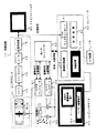
以下、図面を参照して本発明を説明するに、図1は本発明を適用した装置の一例の構成を示すブロック図である。 Hereinafter, the present invention will be described with reference to the drawings. FIG. 1 is a block diagram showing a configuration of an example of an apparatus to which the present invention is applied.
この図1において、撮像手段としての撮像装置10は全体としてビデオカメラを示し、被写体(図示せず)から到達する撮像光は、レンズブロック部11のレンズ、絞り等を通して固体撮像素子、例えばCCD12に結像される。そしてこのCCD12で、任意の視野映像が映像信号に変換された後、信号分離(サンプルホールド:SH)/自動利得制御(AGC)装置13に与えられる。
In FIG. 1, an image pickup apparatus 10 as an image pickup means shows a video camera as a whole, and image pickup light reaching from a subject (not shown) passes through a lens, a diaphragm, etc. of a
信号分離/自動利得制御装置13では、CCD12からの映像出力信号が、例えば所定の画素クロックに従ってサンプルホールドされると共に、例えばオートアイリス(AE)の制御信号によって所定のゲインを持つように自動利得制御が行われる。かくして得られた映像出力信号は、A/D変換装置14を介して信号処理装置15に供給される。
In the signal separation / automatic
信号処理装置15では、入力されてきた信号が、輝度、色差、ビデオ信号といった各信号に変換され、映像信号としてテレビジョンモニタ20や、パーソナルコンピュータ等の後述するコンピュータ装置30のビデオキャプチャーボード31に供給される。これによってこのビデオキャプチャーボード31に供給された映像信号が、順次コンピュータ装置30に取り込まれる。
In the
また、撮像装置10のレンズブロック部11は、変倍用のレンズを駆動することによって撮像する画角を変化させることが可能なズームレンズである。そして後述するカメラコントローラ41からの駆動命令によって、モータ、例えばズーム用ステッピングモータ16が回転されて、上述の変倍用のレンズが駆動される如く構成されている。
The
カメラコントローラ41は、撮像装置10のレンズ制御(フォーカス、ズーム)、露出制御(絞り、ゲイン、電子シャッタースピード)、ホワイトバランス制御、画質制御等を常時行うと共に、モードコントローラ42とのインターフェースが行われる。そして例えばズームの駆動要求に対しては、変倍用レンズを要求位置に駆動する制御信号がモータ16の駆動回路(図示せず)に出力されると共に、変倍用レンズの位置情報が常時モードコントローラ42に通信される。
The
さらに撮像装置10は、駆動手段として例えばパン(左右)及びチルト(上下)といった2軸の回転方向の自由度を持つ装置、例えば回転雲台50の上に設置される。そして後述するパンチルタコントローラ43からの駆動命令によって、モータ、例えばパン用ステッピングモータ51及びチルト用ステッピングモータ52が回転されて、回転雲台50が各方向に駆動される如く構成されている。
Further, the imaging device 10 is installed on a device having a degree of freedom in two-axis rotational directions, such as pan (left and right) and tilt (up and down), for example, as a driving unit, for example, a rotating
パンチルタコントローラ43では、モードコントローラ42とのインターフェースが行われる。そして例えばパン、チルトの各方向の駆動要求に対しては、回転雲台50を要求された方向に駆動する制御信号がモータ51、52の駆動回路(図示せず)に出力されると共に、回転雲台50の例えばパン、チルトの各方向の位置情報が常時モードコントローラ42に通信される。
In the
さらにモードコントローラ42は、撮像装置10及び回転雲台50の内部状態や、装置外部からのインターフェース情報に従ってシステム全体の制御を行う。そしてこのモードコントローラ42は、例えばRS232Cによってコンピュータ装置30に接続され、コンピュータ装置30からの絶対位置駆動要求に対して制御が行われる。
Further, the
すなわちモードコントローラ42では、コンピュータ装置30からの絶対位置駆動要求に対し、撮像装置10でその位置を撮像するべく、レンズブロック部11のモータ16及び回転雲台50のモータ51、52を駆動する駆動命令が、カメラコントローラ41及びパンチルタコントローラ43に振り分けられる。
That is, the
それと共に、これらのコントローラ41及び43からの位置情報やレンズ制御情報、露出制御情報、ホワイトバランス制御情報、画質制御情報等の各種の撮影条件がモードコントローラ42を通じてコンピュータ装置30に送信される。
At the same time, various shooting conditions such as position information, lens control information, exposure control information, white balance control information, and image quality control information from these
さらにこのコンピュータ装置30には、記憶装置32と画像処理装置33と制御装置34とが設けられ、これらの装置によってこのコンピュータ装置30は、例えばパノラマ画像の形成のための映像信号処理手段、及び制御手段として使用される。このコンピュータ装置30で形成された映像信号がコンピュータモニタ60に供給されてユーザーインターフェースとされ、この管面上にグラフィック表示される画像を用いて内部処理の条件等が決定される。
Further, the
さらに上述のビデオキャプチャーボード31では、取り込まれた映像信号を任意のクォリティでモニタ60に表示すると共に、キャプチャー信号により任意の画像フォーマット(例えばビットマップ形式、JPEG形式の静止画、動画等)に任意のクォリティでキャプチャーし、ハードディスク等の記憶装置32に記憶することができる。
Further, in the above-described
そしてこの際に、上述の映像信号がキャプチャーされた撮像時刻と、モードコントローラ42から提供された上述の各種の撮影条件が、キャプチャーされた映像信号と共に記憶装置32に記憶される。
At this time, the imaging time when the above-described video signal is captured and the above-described various shooting conditions provided from the
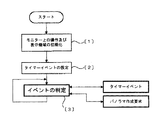
さらにこのコンピュータ装置30で実行される制御アルゴリズムについて図2を用いて説明する。
Further, a control algorithm executed by the
図2においてプログラムがスタートされると、まずステップ〔1〕で撮像映像とパノラマ画像の各々の表示領域をモニタ60上に設定する処理が行われる。これによってモニタ60上には、例えば図1中に示すように、撮像映像の表示領域61と、パノラマ画像の表示領域62とが設定される。そしてこの内の表示領域61に例えば撮像装置10から入力される映像信号が表示される。
When the program is started in FIG. 2, first, in step [1], a process of setting the display areas of the captured video and the panoramic image on the monitor 60 is performed. Thus, on the monitor 60, for example, as shown in FIG. 1, a captured
さらにステップ〔2〕で、例えばモードコントローラ42と周期的に通信を行うためのタイマーが設定される。そしてこれらの初期設定が完了すると、ステップ〔3〕で、各種の発生されるイベントの待機状態に推移される。なお発生されるイベントは、上述のステップ〔2〕で設定されたタイマーイベント(詳細は後述)と、後述のパノラマ画像の作成要求イベントである。
Furthermore, in step [2], for example, a timer for periodically communicating with the
ここでタイマーイベントの詳細について図4を用いて説明する。なおこのタイマーイベントは、例えばモードコントローラ42と周期的に通信を行うために発生されるイベントである。
Details of the timer event will be described with reference to FIG. Note that this timer event is an event that is generated in order to periodically communicate with the
そこでこのイベントが発生されると、ステップ〔11〕で通信ポートの設定が完了しているか否か判断され、初回のみ通信ポートの設定が完了していないのでステップ〔12〕で通信ポートの開設処理が行われる。なお、上述の装置では、通信ポートとして例えばコンピュータ装置30上のRS232Cポートの開設が行われる。
When this event occurs, it is determined in step [11] whether or not the communication port setting has been completed. Since the communication port setting has not been completed only for the first time, the communication port establishment process is performed in step [12]. Is done. In the above-described device, for example, an RS232C port on the
さらに2回目以降のタイマーイベントでは、ステップ〔13〕で受信データの有無が判断され、受信データが有る時はステップ〔14〕で受信データの解析処理が行われる。すなわちこのステップ〔14〕では、例えばモードコントローラ42との通信によって、レンズブロック部11の変倍用レンズの位置情報、回転雲台50のパン、チルトの各方向の位置情報が取得される。そしてこれらの情報からそれぞれズームの倍率情報、パン、チルトの角度情報が取り出される。
Further, in the second and subsequent timer events, the presence / absence of received data is determined in step [13], and when there is received data, the received data is analyzed in step [14]. That is, in this step [14], for example, the position information of the zoom lens of the
次にステップ〔15〕では、データの転送要求(Flag so)の有無が確認される。そして転送要求が有る(True)のときは、データはすでに送信バッファに格納されているので、ステップ〔16〕で直ちにこの送信バッファのデータを用いて転送処理が行われると共に、転送要求が無し(Flag so=False)にされる。 Next, in step [15], it is confirmed whether or not there is a data transfer request (Flag so). When there is a transfer request (True), since the data has already been stored in the transmission buffer, the transfer processing is immediately performed using the data in this transmission buffer in Step [16], and there is no transfer request ( Flag so = False).
そしてステップ〔15〕で転送要求が無い(False)のときは、ステップ〔17〕〔18〕〔19〕でそれぞれ内部カウンタ(req cnt)の値が判断される。ここで(req cnt=0)のときは、ステップ〔17〕からステップ〔20〕に進められて、回転雲台50のモータ51、52を駆動するための絶対位置駆動要求の通信データの転送処理が行われる。
If there is no transfer request (False) in step [15], the value of the internal counter (req cnt) is determined in steps [17] [18] [19]. Here, when (req cnt = 0), the process proceeds from step [17] to step [20] to transfer the communication data of the absolute position drive request for driving the motors 51 and 52 of the
また(req cnt=1)のときは、ステップ〔18〕からステップ〔21〕に進められて、レンズブロック部11のモータ16を駆動するための絶対位置駆動要求の通信データの転送処理が行われる。また(req cnt=2)のときは、ステップ〔19〕からステップ〔22〕に進められて、後述するパノラマ画像の作成処理が行われる。
When (req cnt = 1), the process proceeds from step [18] to step [21], and communication data transfer processing for absolute position drive request for driving the
そしてステップ〔20〕〔21〕が実行された後は、ステップ〔23〕で(req cnt)をカウントアップする処理が行われる。またステップ〔22〕が実行された後は、ステップ〔24〕で(req cnt)を0に戻す処理が行われる。これによって、これらのステップ〔20〕〔21〕〔22〕の処理が、各イベントの処理ごとに循環して実行される。 After steps [20] and [21] are executed, a process of counting up (req cnt) is performed in step [23]. After step [22] is executed, a process of returning (req cnt) to 0 is performed in step [24]. As a result, the processes of these steps [20], [21] and [22] are executed in a circulating manner for each event process.
さらに上述のパノラマ画像の作成処理は以下に述べるようにして行われる。すなわちこのパノラマ画像の作成処理は、例えば図3に示すステップ〔30〕において、パノラマ作成要求(Flag pa)が設定されることによって、上述のタイマーイベントのステップ〔22〕においてこの処理が実行される。 Further, the above panoramic image creation process is performed as described below. That is, this panorama image creation process is executed in step [22] of the above-described timer event by setting a panorama creation request (Flag pa) in step [30] shown in FIG. 3, for example. .
ここでパノラマ画像の作成処理の詳細について図5を用いて説明する。なおこの例では、処理の手順が、内部カウンタ(Pano cnt)に従って行われるものである。 Details of the panorama image creation process will be described with reference to FIG. In this example, the processing procedure is performed according to an internal counter (Pano cnt).
そこでまずステップ〔31〕〔32〕で内部カウンタ(Pano cnt)の値が判断される。ここで(Pano cnt=1)のときは、ステップ〔31〕からステップ〔33〕に進められて、撮像装置10の画角を最広角に設定するようにレンズブロック部11のモータ16を駆動する処理が行われると共に、(Pano cnt)をカウントアップする処理が行われる。なお、画角が最広角に設定されることで、より少ない回数の画像取得でパノラマ画像が形成される。
Therefore, first, in steps [31] and [32], the value of the internal counter (Pano cnt) is determined. Here, when (Pano cnt = 1), the process proceeds from step [31] to step [33], and the
また、(Pano cnt=2)のときは、ステップ〔32〕からステップ〔34〕に進められて、撮像装置10の撮像範囲をパノラマ画像の作成処理で最初に画像取得を行う位置に設定するように、回転雲台50のモータ51、52を駆動する処理が行われると共に、(Pano cnt)をカウントアップする処理が行われる。
When (Pano cnt = 2), the process proceeds from step [32] to step [34], and the imaging range of the imaging device 10 is set to a position where the first image acquisition is performed in the panorama image creation process. In addition, processing for driving the motors 51 and 52 of the
さらに(Pano cnt)が3以上のときは、ステップ〔35〕〔36〕で上述のステップ〔33〕〔34〕で設定されたズーム位置及び撮像範囲に移動されたことが確認される。そしてこれらの設定位置に到達した場合には、ステップ〔37〕で最初の画像取得が行われる。さらにステップ〔38〕で次の画像取得位置に回転雲台50のモータ51、52を駆動する処理が行われる。
Further, when (Pano cnt) is 3 or more, it is confirmed in steps [35] and [36] that the zoom position and the imaging range set in steps [33] and [34] are moved. When these set positions are reached, the first image acquisition is performed in step [37]. Further, in step [38], processing for driving the motors 51 and 52 of the
また、ステップ〔39〕で先に取得した画像の水平、垂直方向への圧縮処理等が行われ、ステップ〔40〕でパノラマ画像の作成状況がモニタ60の表示領域62に表示される。さらにステップ〔41〕で(Pano cnt)をカウントアップする処理が行われ、ステップ〔42〕でパノラマ画像が完成されたか否か判断され、完成していないときは以上の動作が繰り返される。 In step [39], the previously acquired image is compressed in the horizontal and vertical directions, and the panorama image creation status is displayed in the display area 62 of the monitor 60 in step [40]. Further, in step [41], a process of counting up (Pano cnt) is performed. In step [42], it is determined whether or not the panoramic image is completed. When the panorama image is not completed, the above operation is repeated.
そしてステップ〔42〕でパノラマ画像が完成されると、ステップ〔43〕でパノラマ作成要求(Flag pa)が無し(Flag pa=False)にされると共に、ステップ〔44〕で完成されたパノラマ画像が保存されて、動作が終了される。 When the panorama image is completed in step [42], the panorama creation request (Flag pa) is not made (Flag pa = False) in step [43], and the panorama image completed in step [44] is Saved and the operation is finished.
このようにして、例えば回転雲台50によって撮像装置10の撮像範囲が順次移動されながら取得された画像が圧縮処理されながら連結されて、パノラマ画像が形成される。なお、ここで回転雲台50は、指令される目標位置に対して常に同じ方向から進入するように動作される。これによって、例えば画像の連結の際に発生し得る駆動系の機構の遊び(ギアのバックラッシュ等)による連結画像のずれを補正することができるものである。
In this manner, for example, images acquired while the imaging range of the imaging device 10 is sequentially moved by the
そしてこの装置において、上述のパノラマ画像の形成で連結される元の映像信号は、撮像条件が一定でないために、そのまま連結すると露出やホワイトバランス等が部分によって不揃いになり、画質の均一なパノラマ画像を得ることができない。そこで上述の装置においては、コンピュータ装置30の画像処理装置33において画像処理を施し、画質の均一なパノラマ画像を得るようにしている。
In this apparatus, since the original video signals connected in the above-described panoramic image formation are not constant in imaging conditions, if they are connected as they are, the exposure, white balance, etc. will be uneven depending on the part, and the panoramic image with uniform image quality Can't get. Therefore, in the above-described apparatus, the
すなわち図6は、そのための画像処理の一例を示すものである。この図6において、パノラマ画像を形成する各撮像信号には、それぞれの撮像時刻や、位置情報レンズ制御情報、露出制御情報、ホワイトバランス制御情報、画質制御情報等の撮像条件が付属して記憶されている。 That is, FIG. 6 shows an example of image processing for that purpose. In FIG. 6, each imaging signal forming a panoramic image is stored with its imaging time, imaging information such as position information lens control information, exposure control information, white balance control information, and image quality control information. ing.
そこで図6のAに示すような連結される各映像信号から、例えば平均輝度情報を抽出し、それぞれの撮像条件に応じた重み付けをした後、予め設定されている基準輝度と比較して、各画素の補正量を決定(図6のB)する。この補正を実行することによって、パノラマ画像の全体としての露出が均一にされる。 Therefore, for example, average luminance information is extracted from each connected video signal as shown in FIG. 6A, weighted according to each imaging condition, and then compared with a preset reference luminance. The pixel correction amount is determined (B in FIG. 6). By executing this correction, the overall exposure of the panoramic image is made uniform.
さらにその後、例えば一定以上の輝度を持つ画素の赤(R)緑(G)青(B)の積分を求め、白からのずれ量を算出して、各画素に対してのホワイトバランスの調整(図6のC)を行う。これによって、例えば図6のDに示すような画質の均一なパノラマ画像を得ることができる。 After that, for example, the integration of red (R), green (G), and blue (B) of pixels having a certain luminance or higher is obtained, the amount of deviation from white is calculated, and white balance adjustment ( Perform C) of FIG. Thereby, for example, a panoramic image with uniform image quality as shown in FIG. 6D can be obtained.
従ってこの装置において、撮像手段の撮像範囲を変化させ、このような撮像手段からの映像信号を合成して広い画角を有する映像信号を形成すると共に、その際の撮像時刻及び/または撮像条件を記憶することによって、簡単な構成で、撮像時刻や撮像条件等の変化に対して違和感を生じることのないパノラマ画像を、高解像度で得ることができる。 Therefore, in this apparatus, the imaging range of the imaging means is changed, and the video signals from such imaging means are combined to form a video signal having a wide angle of view, and the imaging time and / or imaging conditions at that time are set. By storing, a panoramic image that does not cause a sense of incongruity with changes in imaging time, imaging conditions, and the like can be obtained with high resolution with a simple configuration.
これによって、従来の装置では、高価な広角系のレンズを用いても解像度が低下してしまう恐れがあり、また保存画像に嵌め込み合成してパノラマ画像を形成する方法では、例えば撮像時刻や撮像条件の変化に対して違和感を生じる等の問題があったものを、本発明によればこれらの問題点を解消することができる。 As a result, with conventional devices, the resolution may be lowered even when an expensive wide-angle lens is used, and in the method of forming a panoramic image by fitting into a stored image, for example, the imaging time and the imaging conditions According to the present invention, these problems can be solved in the case where there is a problem such as a sense of incongruity with respect to the change of.
さらに上述の装置において、作成されたパノラマ画像は、上述のコンピュータモニタ60のパノラマ画像の表示領域62に表示される。この場合にモニタ60上には、上述の表示領域61、62と共に、例えば図7に示すような操作ボタン63が表示される。
Further, in the above-described apparatus, the created panorama image is displayed in the panorama image display area 62 of the computer monitor 60 described above. In this case, an operation button 63 as shown in FIG. 7, for example, is displayed on the monitor 60 together with the
そしてこのようなコンピュータモニタ60上において、使用者が、ポインティングデバイス(マウス)等の入力手段によって表示領域62中の任意の画素を指示すると、例えば表示領域62の左上隅を原点として指示された画素の座標が取得され、取得された指示点の座標がコンピュータ装置30に転送される。
On such a computer monitor 60, when the user designates an arbitrary pixel in the display area 62 by an input means such as a pointing device (mouse), the designated pixel is set with the upper left corner of the display area 62 as an origin, for example. Are obtained, and the obtained coordinates of the designated point are transferred to the
そこでコンピュータ装置30では、転送された座標から指示点の画素を含む撮像領域を判別し、この撮像領域の座標と移動命令がモードコントローラ42に送信される。これによってモードコントローラ42では、上述のタイマーイベントのステップ〔14〕で受信されたデータが解析処理され、この解析されたデータに従って回転雲台50を駆動して、指示された画素を含む目標の撮像領域を撮像するように制御が行われる。
Therefore, the
すなわち使用者は、例えばコンピュータモニタ60上のパノラマ画像を確認しながら、ポインティングデバイス(マウス)等の入力手段を利用して、詳しく観察したい場所を指示する。この指示によって、撮像装置10は回転雲台50により指示された方向に向けられ、その場所の現在の映像が撮像映像の表示領域61に表示される。
That is, for example, while confirming a panoramic image on the computer monitor 60, the user uses an input means such as a pointing device (mouse) to instruct a place to be observed in detail. In response to this instruction, the imaging apparatus 10 is directed in the direction instructed by the
そして使用者は、この撮像映像の表示領域61に表示される画像を観察しながら、記録したい映像になったらモニタ60上の操作ボタン63の記録開始ボタンをポインティングデバイス(マウス)等で押すことによって、必要な映像をハードディスク等の記憶装置32に記憶(保存)することができる。
Then, the user observes the image displayed in the
なおこの保存される映像は、使用者が記録開始ボタンを押した瞬間の静止画であってもよいし、また任意の操作ボタン63の操作によって所望の長さの動画を保存することもできる。あるいは記憶装置32の容量に余裕がない場合には、静止画を利用した間欠動画を保存してもよい。そして、これらの静止画、動画、間欠動画の記憶(保存)の際にも、上述の撮像時刻や撮像条件のデータが付属して記憶される。
The stored image may be a still image at the moment when the user presses the recording start button, or a moving image having a desired length can be stored by operating any operation button 63. Or when there is no room in the capacity of the
そこで、さらにこのようにして記憶(保存)された映像を用いてのパノラマ画像の作成が次のようにして行われる。 Therefore, a panoramic image is created using the video stored (saved) in this manner as follows.
すなわち、上述の図7に示すようなコンピュータモニタ60の表示において、使用者が、ポインティングデバイス(マウス)等の入力手段によって表示領域62中の任意の画素を指示すると、例えば表示領域62の左上隅を原点として指示された画素の座標が取得され、取得された指示点の座標がコンピュータ装置30に転送される。
That is, in the display on the computer monitor 60 as shown in FIG. 7 described above, when the user designates an arbitrary pixel in the display area 62 by an input means such as a pointing device (mouse), for example, the upper left corner of the display area 62 The coordinates of the designated pixel are obtained with the origin as the origin, and the obtained coordinates of the designated point are transferred to the
そこでコンピュータ装置30では、転送された座標から指示点の画素を含む撮像領域を判別し、この撮像領域を含む部分画像が保存されている場合には、パノラマ画像上にその領域を例えば着色された境界線で囲う等によって表示すると共に、そこに保存された画像を表示する。これによってパノラマ画像上で所望の領域の保存画像を見ることができる。
Therefore, the
この場合に、パノラマ画像上では画像は圧縮されて表示されるので、詳細に見たい場合には表示領域62外に拡大して表示することもできる。その場合には、例えば撮像映像の表示領域61への表示や、拡大補完してモニタ60の画面全体に表示することもできる。
In this case, since the image is compressed and displayed on the panoramic image, the image can be enlarged and displayed outside the display area 62 when the user wants to see details. In this case, for example, the captured image can be displayed on the
また、上述の指示された同一の領域に複数の画像が保存されている場合には、例えばモニタ60上の操作ボタン63の操作によって所望の画像を検索することができる。この場合に画像の検索は、上述の映像信号と共に記憶された撮像時刻や撮像条件等を指定して行うことができる。 If a plurality of images are stored in the same designated area, a desired image can be searched by operating the operation button 63 on the monitor 60, for example. In this case, the image search can be performed by designating the imaging time, the imaging conditions, etc. stored together with the above video signal.
さらに上述のパノラマ画像上で保存画像を見る場合に、指定された領域の画像を単純にパノラマ画像に重ねて表示すると、その撮影条件に差異がある場合に不自然な画像となってしまう。そこでそのような場合には、上述の図6に示したと同様の処理を行うことで、画質の均一なパノラマ画像を得ることができる。 Further, when viewing a stored image on the above-described panoramic image, if an image of a specified area is simply displayed superimposed on the panoramic image, the image becomes unnatural when there is a difference in shooting conditions. In such a case, a panoramic image with uniform image quality can be obtained by performing the same processing as shown in FIG.
従ってこの装置において、形成された映像信号を表示する表示手段上で指示された部分領域の映像信号の撮像条件に従って他の部分領域の映像信号を補正することによって、パノラマ画像の一部分のみを変更した場合にも、撮像時刻や撮像条件等の変化に対して違和感を生じることのないパノラマ画像を得ることができる。 Therefore, in this apparatus, only a part of the panoramic image is changed by correcting the video signal of the other partial area according to the imaging condition of the video signal of the partial area instructed on the display means for displaying the formed video signal. Even in this case, it is possible to obtain a panoramic image that does not give a sense of incongruity to changes in imaging time, imaging conditions, and the like.
これによって、従来の装置では、高価な広角系のレンズを用いても解像度が低下してしまう恐れがあり、また例えば指示された部分領域の映像信号を嵌め込み合成してパノラマ画像を形成する方法では、例えば撮像時刻や撮像条件の変化に対して違和感を生じる等の問題があったものを、本発明によればこれらの問題点を解消することができる。 As a result, with conventional devices, there is a risk that the resolution will be lowered even if an expensive wide-angle lens is used, and for example, a method of forming a panoramic image by inserting and synthesizing the video signal of the designated partial area. For example, according to the present invention, these problems can be solved when there is a problem such as an uncomfortable feeling with respect to changes in imaging time or imaging conditions.
なお、上述の装置において、上述の図3のステップ〔30〕におけるパノラマ作成要求(Flag pa)の設定は、例えば使用者がモニタ60上に示されるボタンを操作したり、いわゆるリモートコントロールによって行うこともできるが、さらに撮影時刻の指定による設定や、画像認識(処理)、各種のセンサの検知等によって自動的に設定が行われるようにすることもできる。 In the above-described apparatus, the panorama creation request (Flag pa) in step [30] in FIG. 3 is set by, for example, a user operating a button shown on the monitor 60 or by so-called remote control. However, the setting can also be automatically performed by setting by specifying the photographing time, image recognition (processing), detection of various sensors, and the like.
すなわち、例えば撮影時刻の指定による設定を行う場合には、例えば図1のコンピュータ装置30に付属されるキーボードやいわゆるマウス等のポインティングデバイス等の入力装置35によってパノラマ撮影を行う時刻を設定することにより、その時刻が記憶装置32に保存される。
That is, for example, when setting is performed by specifying the shooting time, the panorama shooting time is set by the
そして例えば図2のイベント判定のステップ〔3〕において、コンピュータ装置30に内蔵された時計(図示せず)と保存された設定時刻とを比較し、両者が一致したときにパノラマ画像の作成要求が指令され、撮影が行われる。なお、時刻は複数を設定したり、また一定の時間間隔を指示することによって、自動的に連続撮影を行うことも可能である。
Then, for example, in the event determination step [3] of FIG. 2, a clock (not shown) built in the
あるいは、撮像装置10から得られる映像情報を現在と過去とで比較して、その差異を検出して自動的にパノラマ画像の作成要求が指令されるようにすることもできる。ここで得られる映像情報とは、画像の輝度、色差、輪郭、カラーバランス等である。 Alternatively, the video information obtained from the imaging device 10 can be compared between the present and the past, and the difference can be detected to automatically issue a panoramic image creation request. The video information obtained here is image brightness, color difference, contour, color balance, and the like.
そこで例えば輝度情報を利用する方法では、撮像装置10から現在映出されている画像の部分の輝度平均が、撮影されて記憶装置32に保存されているパノラマ画像の一部分の輝度平均と比較される。そしてその差が一定以上に開いたときにパノラマ画像の作成要求が指令され、撮影が行われる。そして作成されたパノラマ画像は直ちに、モニタ60等に映出される。
Therefore, for example, in a method using luminance information, the average luminance of the portion of the image currently displayed from the imaging device 10 is compared with the average luminance of a portion of the panoramic image that has been captured and stored in the
なおこの方法では、風景等の撮影において、時間経過と共に周囲の明るさが変化しているような場合に、自動的にパノラマ画像が撮影更新されるので、常に現在の撮像装置10で撮像されている映像に近いパノラマ画像を提供することが可能となるものである。 In this method, when shooting the scenery or the like, when the ambient brightness changes with time, the panoramic image is automatically captured and updated, so that the current imaging device 10 always captures the image. It is possible to provide a panoramic image that is close to the existing video.
また、例えば図8に示すように、撮像装置10で撮像されている被写体について代表点を指定し、その輝度と色差情報を組み合わせてモデル化して、その位置情報と共に記憶装置32に保存する。そして同一の範囲を撮像装置10により常に撮像し、被写体モデルの位置座標に差異が生じたときにパノラマ画像の作成要求が指令され、撮影を行うことが可能である。
For example, as shown in FIG. 8, a representative point is designated for the subject imaged by the imaging device 10, and the luminance and color difference information are combined and modeled, and stored in the
すなわち図8のAにおいて、元の被写体モデルの位置座標(X0、Y0)が、図8のBに示すように位置座標(X1、Y1)になったときに、X0≠X1またはY0≠Y1を判断して、図8のCに示すように被写体が移動したと認識し、パノラマ画像の作成要求を指令して、撮影を開始することができる。この方法によって、上述の装置を動態監視システムとして利用することができる。 That is, in A of FIG. 8, when the position coordinates (X0, Y0) of the original subject model become the position coordinates (X1, Y1) as shown in B of FIG. 8, X0 ≠ X1 or Y0 ≠ Y1 is set. As a result of the determination, it can be recognized that the subject has moved as shown in FIG. 8C, a panoramic image creation request can be instructed, and shooting can be started. By this method, the above-described apparatus can be used as a dynamic monitoring system.
この他、マイクロフォンのような音声情報を得られる手段を備え、音声の検出に伴ってパノラマ画像の作成要求を指令して撮影を開始することも可能である。この場合には、例えば図9に示すように、撮像装置10が回転雲台50等の駆動手段によって移動されて撮像可能な範囲に、例えば指向性マイクロフォンを複数設置する。これらの指向性マイクロフォンで収音された音声情報が図1のコンピュータ装置30に入力される。
In addition, it is also possible to provide a means for obtaining audio information such as a microphone, and start imaging by instructing a panoramic image creation request in accordance with detection of audio. In this case, for example, as shown in FIG. 9, for example, a plurality of directional microphones are installed in a range where the imaging apparatus 10 is moved by a driving unit such as a
そしてこのコンピュータ装置30では、マイクロフォンで収音された音声情報の中に特定の音声情報を検出すると、パノラマ画像の作成要求を指令すると共に、その音声情報を検出したマイクロフォンの指向性がどの方向であるか記憶し、必要ならばその方向から撮影を行ってパノラマ画像を更新することができる。
In the
このようにして、特定の音声情報の検出によって被写体の変化を認識し、パノラマ画像の作成要求を指令して、撮影を開始することができる。またこの方法では、同様に光センサや焦電センサ等の各種センサを用いて、それぞれ必要に応じた検出と、パノラマ画像の更新を行うことができるものである。 In this way, it is possible to recognize a change in the subject by detecting specific audio information, instruct a panoramic image creation request, and start shooting. In this method, similarly, various sensors such as an optical sensor and a pyroelectric sensor can be used to perform detection and update of a panoramic image as necessary.
さらに上述の図1の装置において、記録手段としての記憶装置32を設けたことによって、この装置は記録装置として実施することができる。なおこの場合に記憶装置32では、撮像装置10からの映像信号と共に、その撮像の際の撮像時刻や撮像条件が記録されるものである。
Further, in the apparatus of FIG. 1 described above, by providing the
従ってこの装置において、撮像手段の撮像範囲を変化させ、このような撮像手段からの映像信号と、その撮像の際の撮像時刻や撮像条件を記録することによって、簡単な構成で、撮像時刻や撮像条件等の変化に対して違和感を生じることのないパノラマ画像を、高解像度で記録することができるものである。 Therefore, in this apparatus, by changing the imaging range of the imaging means and recording the video signal from such imaging means and the imaging time and imaging conditions at the time of imaging, the imaging time and imaging can be made with a simple configuration. A panoramic image that does not give a sense of incongruity to changes in conditions or the like can be recorded with high resolution.
さらに上述の図1の装置において、映像信号の処理手段としての画像処理装置33を設けたことによって、この装置は処理装置として実施することができる。なおこの場合に画像処理装置33では、撮像装置10からの映像信号を連結してパノラマ画像を形成すると共に、撮像時刻や撮像条件等の変化に対して連結される映像信号の補正を行うものである。
Further, in the apparatus of FIG. 1 described above, the
従ってこの装置において、撮像手段の撮像範囲を変化させ、このような撮像手段からの映像信号と、その撮像の際の撮像時刻や撮像条件を記録することによって、簡単な構成で、撮像時刻や撮像条件等の変化に対して違和感を生じることのないパノラマ画像を、高解像度で形成することができるものである。 Therefore, in this apparatus, by changing the imaging range of the imaging means and recording the video signal from such imaging means and the imaging time and imaging conditions at the time of imaging, the imaging time and imaging can be made with a simple configuration. A panoramic image that does not give a sense of incongruity to changes in conditions or the like can be formed with high resolution.
さらに上述の図1の装置において、表示手段としてのコンピュータモニタ60を設けたことによって、この装置は表示装置として実施することができる。 Further, in the apparatus of FIG. 1 described above, by providing a computer monitor 60 as a display means, this apparatus can be implemented as a display apparatus.
従ってこの装置において、撮像手段の撮像範囲を変化させ、このような撮像手段からの映像信号を合成して広い画角を有する映像信号を形成すると共に、この映像信号を表示手段に表示することによって、簡単な構成で、撮像時刻や撮像条件等の変化に対して違和感を生じることのないパノラマ画像を、高解像度で観視することができるものである。 Therefore, in this apparatus, by changing the imaging range of the imaging means, combining the video signals from such imaging means to form a video signal having a wide angle of view, and displaying this video signal on the display means With a simple configuration, it is possible to view a panoramic image with high resolution that does not give a sense of incongruity to changes in imaging time, imaging conditions, and the like.
さらに上述の図1の装置において、再生手段としての記憶装置32を設けたことによって、この装置は再生装置として実施することができる。なおこの場合に記憶装置32では、撮像装置10からの映像信号と、その撮像の際の撮像時刻や撮像条件が記録されて再生されるものである。
Further, in the apparatus of FIG. 1 described above, by providing the
従ってこの装置において、撮像範囲が順次変化された映像信号、その撮像の際の撮像時刻や撮像条件を再生し、この再生映像信号を合成して広い画角を有する映像信号を形成することによって、簡単な構成で、撮像時刻や撮像条件等の変化に対して違和感を生じることのないパノラマ画像を、高解像度で再生することができるものである。 Therefore, in this apparatus, by reproducing the video signal in which the imaging range is sequentially changed, the imaging time and imaging conditions at the time of imaging, and synthesizing the reproduced video signal to form a video signal having a wide angle of view, With a simple configuration, a panoramic image that does not give a sense of incongruity to changes in imaging time, imaging conditions, etc. can be reproduced with high resolution.
さらに上述の図1の装置において、コンピュータ装置30からコンピュータモニタ60に送られる信号をモデム(図示せず)を介して、例えばインターネットのようなコンピュータネットワークに送出することによって、この装置は伝送装置として実施することができる。
Further, in the apparatus of FIG. 1 described above, a signal transmitted from the
すなわちこのようなコンピュータネットワークにおいて、遠隔地に設置された撮像装置10〜コンピュータ装置30〜回転雲台50の構成に対して、任意のコンピュータ装置と表示装置とモデムを有する使用者側の装置からネットワークを通じてアクセスを行う。これによって、その時の撮像画像と、例えばコンピュータ装置30の記憶装置32に保存されているパノラマ画像を、例えば図1のモニタ60と同様の画面構成で使用者側の表示装置に得ることができる。
That is, in such a computer network, with respect to the configuration of the imaging device 10 to the
従ってこの装置において、遠隔地に設置された撮像手段で撮像された映像信号を合成して広い画角を有する映像信号を形成することによって、簡単な構成で、天候や時間等の変化に対して違和感を生じることのないパノラマ画像を、高解像度で観視することができるものである。 Therefore, in this apparatus, by synthesizing the video signals picked up by the image pickup means installed at a remote place to form a video signal having a wide angle of view, it is possible to cope with changes in weather, time, etc. with a simple configuration. A panoramic image that does not cause a sense of incongruity can be viewed with high resolution.
さらに上述の図1の装置において、記憶装置32の記録媒体を着脱自在のものとし、この記録媒体を取り出すことによって、この装置は記録媒体として実施することができる。
Further, in the apparatus of FIG. 1 described above, the recording medium of the
従ってこの装置において、撮像手段の撮像範囲を変化させ、このような撮像手段からの映像信号と、その撮像の際の撮像時刻や撮像条件を記録することによって、この記録媒体を再生し連結することで、簡単な構成で、撮像時刻や撮像条件等の変化に対して違和感を生じることのないパノラマ画像を、高解像度で得ることができるものである。 Therefore, in this apparatus, by changing the imaging range of the imaging means and recording the video signal from such imaging means and the imaging time and imaging conditions at the time of imaging, this recording medium is reproduced and connected. Thus, it is possible to obtain a panoramic image with high resolution with a simple configuration and without causing a sense of incongruity with respect to changes in imaging time, imaging conditions, and the like.
またこれらの装置において、形成された映像信号を表示する表示手段上で指示された部分領域の映像信号の撮像条件に従って他の部分領域の映像信号を補正することによって、パノラマ画像の一部分のみを変更した場合にも、撮像時刻や撮像条件等の変化に対して違和感を生じることのないパノラマ画像を得ることができるものである。 In these devices, only a part of the panoramic image is changed by correcting the video signal of the other partial area according to the imaging condition of the video signal of the partial area instructed on the display means for displaying the formed video signal. Even in this case, it is possible to obtain a panoramic image that does not give a sense of incongruity to changes in imaging time, imaging conditions, and the like.
さらに上述の装置において、撮像の際の撮像時刻及び/または撮像条件等の情報を、撮像された映像信号と共に記憶する際には、例えば図10のAに示すように、通常の画像形式の先頭にこれらの情報を付加して保存する。あるいは、同図のBに示すように、各映像のファイルとは別に、撮像時刻及び/または撮像条件等の情報だけをまとめて記憶し、各映像ファイルと対応づける方法を用いることができる。 Furthermore, in the above-described apparatus, when storing information such as the imaging time and / or imaging conditions at the time of imaging together with the captured video signal, for example, as shown in FIG. This information is added to and stored. Alternatively, as shown in FIG. 7B, separately from each video file, only information such as the imaging time and / or imaging conditions can be stored together and associated with each video file.
なお、上述の装置においては、例えば撮像装置10の1台を回転雲台50によって撮像範囲を変化させてパノラマ画像の撮像を行うこととしたが、これはこのような手段に限られるものではない。すなわち、このようなパノラマ画像の撮像を行う手段としては、例えばデジタル静止画カメラを用いて撮像された一連の映像を基に、あるいはビデオカメラにより撮像された動画像を基にパノラマ画像を作成することができる。
In the above-described apparatus, for example, one imaging apparatus 10 is used to change the imaging range by the
また、回転雲台50を用いる代わりに、例えば複数台の撮像装置をパノラマ画像を形成する各方向に向けて配置し、これらの撮像装置からの映像信号を順次切り換えて駆動手段としても、同様の映像信号の取得を行うことができるものである。
Further, instead of using the
さらに上述の装置においては、記憶された撮像時刻や撮像条件等の情報を用いて撮像された映像信号の検索を迅速且つ容易に行うことができる。これによって、例えば上述のモニタ60上の操作ボタン63の操作によって所望の画像を検索する場合にも、検索を極めて円滑に行うことができるものである。 Further, in the above-described apparatus, it is possible to quickly and easily search for a video signal captured using information such as stored imaging time and imaging conditions. Thus, for example, when a desired image is searched for by operating the operation button 63 on the monitor 60 described above, the search can be performed very smoothly.
10…撮像装置、11…レンズブロック部、12…CCD、13…信号分離/自動利得制御装置、14…A/D変換装置、15…信号処理装置、16…ズーム用ステッピングモータ、20…テレビジョンモニタ、30…コンピュータ、31…ビデオキャプチャーボード、32…記憶装置、33…画像処理装置、34…制御装置、35…入力装置、41…カメラコントローラ、42…モードコントローラ、43…パンチルタコントローラ、50…回転雲台、51…パン用ステッピングモータ、52…チルト用ステッピングモータ、60…コンピュータモニタ、61…撮像映像の表示領域、62…パノラマ画像の表示領域
DESCRIPTION OF SYMBOLS 10 ... Imaging device, 11 ... Lens block part, 12 ... CCD, 13 ... Signal separation / automatic gain control device, 14 ... A / D conversion device, 15 ... Signal processing device, 16 ... Stepping motor for zoom, 20 ...
Claims (7)
上記撮像手段の撮像範囲を変化させる駆動手段と、
上記撮像手段からの映像信号が供給され上記撮像手段の一つの撮像範囲より広い画角を有するパノラマ映像信号を形成する映像信号処理手段と、
現在の上記映像信号と過去の上記映像信号との差異が所定以上になれば、上記撮像手段の撮像範囲を最広角に設定して撮影するように上記撮像手段を制御し、上記パノラマ映像信号を形成するように上記駆動手段を制御する制御手段と
を有する撮像装置。 Imaging means for generating a video signal;
Driving means for changing the imaging range of the imaging means;
Video signal processing means for supplying a video signal from the imaging means to form a panoramic video signal having a wider angle of view than one imaging range of the imaging means;
If the difference between the current video signal and the past video signal is greater than or equal to a predetermined value, the imaging means is controlled to set the imaging range of the imaging means to the widest angle, and the panoramic video signal is that an imaging device having a control means for controlling said drive means so as to form.
上記撮像手段の撮像範囲を湾曲させて上記撮像手段の本来の撮像範囲より広い画角の撮像を行わせる光学手段と、
上記撮像手段からの映像信号が供給され上記歪曲させて撮像された映像信号を正規化して上記撮像手段の本来の撮像範囲より広い画角を有するパノラマ映像信号を形成する映像信号処理手段と、
現在の上記映像信号と過去の上記映像信号との差異が所定以上になれば、上記撮像手段の撮像範囲を最広角に設定して撮影するように上記撮像手段を制御し、上記パノラマ映像信号を形成するように上記駆動手段を制御する制御手段と
を有する撮像装置。 Imaging means for generating a video signal;
An optical unit configured to bend the imaging range of the imaging unit and perform imaging with a wider angle of view than the original imaging range of the imaging unit;
Video signal processing means for normalizing the video signal supplied with the video signal from the imaging means and distorted to form a panoramic video signal having a wider angle of view than the original imaging range of the imaging means;
If the difference between the current video signal and the past video signal is greater than or equal to a predetermined value, the imaging means is controlled to set the imaging range of the imaging means to the widest angle, and the panoramic video signal is that an imaging device having a control means for controlling said drive means so as to form.
上記撮像手段の撮像範囲を変化させる駆動手段と、Driving means for changing the imaging range of the imaging means;
上記撮像手段からの映像信号が供給され上記撮像手段の一つの撮像範囲より広い画角を有するパノラマ映像信号を形成する映像信号処理手段と、Video signal processing means for supplying a video signal from the imaging means to form a panoramic video signal having a wider angle of view than one imaging range of the imaging means;
現在の上記映像信号と過去の上記映像信号との差異が所定以上になれば、上記撮像手段の撮像範囲を最広角に設定して撮影するように上記撮像手段を制御し、上記パノラマ映像信号を形成するように上記駆動手段を制御する制御手段と、If the difference between the current video signal and the past video signal is greater than or equal to a predetermined value, the imaging means is controlled to set the imaging range of the imaging means to the widest angle, and the panoramic video signal is Control means for controlling the drive means to form;
上記映像信号処理手段で形成された映像信号を表示する表示手段とDisplay means for displaying the video signal formed by the video signal processing means;
を有する表示装置。A display device.
上記撮像手段の撮像範囲を湾曲させて上記撮像手段の本来の撮像範囲より広い画角の撮像を行わせる光学手段と、
上記撮像手段からの映像信号が供給され上記歪曲させて撮像された映像信号を正規化して上記撮像手段の本来の撮像範囲より広い画角を有するパノラマ映像信号を形成する映像信号処理手段と、
現在の上記映像信号と過去の上記映像信号との差異が所定以上になれば、上記撮像手段の撮像範囲を最広角に設定して撮影するように上記撮像手段を制御し、上記パノラマ映像信号を形成するように上記駆動手段を制御する制御手段と、
上記映像信号処理手段で形成された映像信号を表示する表示手段と
を有する表示装置。 Imaging means for generating a video signal;
An optical unit configured to bend the imaging range of the imaging unit and perform imaging with a wider angle of view than the original imaging range of the imaging unit;
Video signal processing means for normalizing the video signal supplied with the video signal from the imaging means and distorted to form a panoramic video signal having a wider angle of view than the original imaging range of the imaging means;
If the difference between the current video signal and the past video signal is greater than or equal to a predetermined value, the imaging means is controlled to set the imaging range of the imaging means to the widest angle, and the panoramic video signal is Control means for controlling the drive means to form;
Viewing device that having a display means for displaying a video signal formed by the video signal processing means.
Priority Applications (1)
| Application Number | Priority Date | Filing Date | Title |
|---|---|---|---|
| JP2005254056A JP4148251B2 (en) | 2005-09-01 | 2005-09-01 | Imaging device and display device |
Applications Claiming Priority (1)
| Application Number | Priority Date | Filing Date | Title |
|---|---|---|---|
| JP2005254056A JP4148251B2 (en) | 2005-09-01 | 2005-09-01 | Imaging device and display device |
Related Parent Applications (1)
| Application Number | Title | Priority Date | Filing Date |
|---|---|---|---|
| JP09913497A Division JP3994469B2 (en) | 1997-04-16 | 1997-04-16 | Imaging device, display device, and recording device |
Related Child Applications (1)
| Application Number | Title | Priority Date | Filing Date |
|---|---|---|---|
| JP2008117861A Division JP2008236783A (en) | 2008-04-28 | 2008-04-28 | Control apparatus, control method, and monitoring system |
Publications (3)
| Publication Number | Publication Date |
|---|---|
| JP2005348449A JP2005348449A (en) | 2005-12-15 |
| JP2005348449A5 JP2005348449A5 (en) | 2006-02-09 |
| JP4148251B2 true JP4148251B2 (en) | 2008-09-10 |
Family
ID=35500324
Family Applications (1)
| Application Number | Title | Priority Date | Filing Date |
|---|---|---|---|
| JP2005254056A Expired - Fee Related JP4148251B2 (en) | 2005-09-01 | 2005-09-01 | Imaging device and display device |
Country Status (1)
| Country | Link |
|---|---|
| JP (1) | JP4148251B2 (en) |
Cited By (1)
| Publication number | Priority date | Publication date | Assignee | Title |
|---|---|---|---|---|
| CN107613195A (en) * | 2017-08-31 | 2018-01-19 | 清远市奇盛科技有限公司 | Mobile phone full-view image playing device |
Families Citing this family (2)
| Publication number | Priority date | Publication date | Assignee | Title |
|---|---|---|---|---|
| JP2008236783A (en) * | 2008-04-28 | 2008-10-02 | Sony Corp | Control apparatus, control method, and monitoring system |
| CN103561209A (en) * | 2013-10-21 | 2014-02-05 | 广东明创软件科技有限公司 | Method for shooting panoramic photos or videos based on mobile terminal and mobile terminal |
-
2005
- 2005-09-01 JP JP2005254056A patent/JP4148251B2/en not_active Expired - Fee Related
Cited By (2)
| Publication number | Priority date | Publication date | Assignee | Title |
|---|---|---|---|---|
| CN107613195A (en) * | 2017-08-31 | 2018-01-19 | 清远市奇盛科技有限公司 | Mobile phone full-view image playing device |
| CN107613195B (en) * | 2017-08-31 | 2020-02-18 | 清远市奇盛科技有限公司 | Mobile phone panoramic image playing device |
Also Published As
| Publication number | Publication date |
|---|---|
| JP2005348449A (en) | 2005-12-15 |
Similar Documents
| Publication | Publication Date | Title |
|---|---|---|
| JP4356689B2 (en) | CAMERA SYSTEM, CAMERA CONTROL DEVICE, PANORAMA IMAGE CREATION METHOD, AND COMPUTER PROGRAM | |
| CN110022431B (en) | Image pickup apparatus, image pickup method, display apparatus, and display method | |
| JP4396500B2 (en) | Imaging apparatus, image orientation adjustment method, and program | |
| JP2001251551A (en) | Electronic camera | |
| JP5578442B2 (en) | Imaging apparatus, image composition method, and program | |
| JP2002112008A (en) | Image processing system and recording medium recording image processing program | |
| JP5200821B2 (en) | Imaging apparatus and program thereof | |
| JP4957825B2 (en) | Imaging apparatus and program | |
| JP3798544B2 (en) | Imaging control apparatus and imaging control method | |
| JPH1118003A (en) | Panorama image-pickup device | |
| JP4583717B2 (en) | Imaging apparatus and method, image information providing system, program, and control apparatus | |
| JP3994469B2 (en) | Imaging device, display device, and recording device | |
| JP3948050B2 (en) | Imaging, storage, processing, display, playback, transmission device and recording medium | |
| JP4148251B2 (en) | Imaging device and display device | |
| JP3444281B2 (en) | IMAGE PROCESSING SYSTEM, IMAGING DEVICE, IMAGE PROCESSING METHOD, AND RECORDING MEDIUM CONTAINING PROCESSING PROGRAM OF THE METHOD | |
| JP2001036898A (en) | Camera system for generating panoramic video | |
| JP2005348449A5 (en) | ||
| JP3730630B2 (en) | Imaging apparatus and imaging method | |
| JP4293280B2 (en) | Control device, control method and monitoring system | |
| JP2008017198A (en) | Device and method for calculating light source color, and photographing device | |
| JP2005348448A (en) | Panorama imaging apparatus | |
| JP3957168B2 (en) | Motion control camera | |
| JP2006050655A (en) | Imaging apparatus and display device | |
| JP3826506B2 (en) | Information display method | |
| JP2008236783A (en) | Control apparatus, control method, and monitoring system |
Legal Events
| Date | Code | Title | Description |
|---|---|---|---|
| A521 | Request for written amendment filed |
Free format text: JAPANESE INTERMEDIATE CODE: A523 Effective date: 20050929 |
|
| A621 | Written request for application examination |
Free format text: JAPANESE INTERMEDIATE CODE: A621 Effective date: 20050929 |
|
| A521 | Request for written amendment filed |
Free format text: JAPANESE INTERMEDIATE CODE: A523 Effective date: 20051101 |
|
| A131 | Notification of reasons for refusal |
Free format text: JAPANESE INTERMEDIATE CODE: A131 Effective date: 20080226 |
|
| A521 | Request for written amendment filed |
Free format text: JAPANESE INTERMEDIATE CODE: A523 Effective date: 20080428 |
|
| TRDD | Decision of grant or rejection written | ||
| A01 | Written decision to grant a patent or to grant a registration (utility model) |
Free format text: JAPANESE INTERMEDIATE CODE: A01 Effective date: 20080603 |
|
| A01 | Written decision to grant a patent or to grant a registration (utility model) |
Free format text: JAPANESE INTERMEDIATE CODE: A01 |
|
| A61 | First payment of annual fees (during grant procedure) |
Free format text: JAPANESE INTERMEDIATE CODE: A61 Effective date: 20080616 |
|
| FPAY | Renewal fee payment (event date is renewal date of database) |
Free format text: PAYMENT UNTIL: 20110704 Year of fee payment: 3 |
|
| FPAY | Renewal fee payment (event date is renewal date of database) |
Free format text: PAYMENT UNTIL: 20110704 Year of fee payment: 3 |
|
| FPAY | Renewal fee payment (event date is renewal date of database) |
Free format text: PAYMENT UNTIL: 20110704 Year of fee payment: 3 |
|
| FPAY | Renewal fee payment (event date is renewal date of database) |
Free format text: PAYMENT UNTIL: 20120704 Year of fee payment: 4 |
|
| LAPS | Cancellation because of no payment of annual fees |