JP4147568B2 - Electromagnetic intake / exhaust system - Google Patents
Electromagnetic intake / exhaust system Download PDFInfo
- Publication number
- JP4147568B2 JP4147568B2 JP2000048598A JP2000048598A JP4147568B2 JP 4147568 B2 JP4147568 B2 JP 4147568B2 JP 2000048598 A JP2000048598 A JP 2000048598A JP 2000048598 A JP2000048598 A JP 2000048598A JP 4147568 B2 JP4147568 B2 JP 4147568B2
- Authority
- JP
- Japan
- Prior art keywords
- intake
- damper
- exhaust valve
- exhaust
- piston
- Prior art date
- Legal status (The legal status is an assumption and is not a legal conclusion. Google has not performed a legal analysis and makes no representation as to the accuracy of the status listed.)
- Expired - Fee Related
Links
Images


Landscapes
- Valve Device For Special Equipments (AREA)
- Output Control And Ontrol Of Special Type Engine (AREA)
- Magnetically Actuated Valves (AREA)
- Fluid-Damping Devices (AREA)
Description
【0001】
【発明の属する技術分野】
本発明は、内燃機関(以下、「内燃機関」をエンジンという)の吸気弁または排気弁を電磁力により駆動する電磁式吸排気装置に関する。
【0002】
【従来の技術】
従来より、エンジンの吸気弁または排気弁を電磁力により駆動する電磁式吸排気装置が知られている。このような電磁式吸排気装置においては、吸気弁または排気弁の開閉タイミングをエンジンの運転条件に応じて吸気または排気が良好に行われるように制御することにより、エンジンの安定性向上、燃費の向上、あるいは排気エミッションを低減することが可能である。
【0003】
例えばエンジンの低負荷時においては吸入空気量が少ないため、エンジンのシリンダ内に燃焼を悪化させる残留排気ガスが少ないことが望ましい。吸気弁および排気弁の弁部材が同時に開いている期間(オーバーラップ期間)において、吸気側はスロットルによって大気圧よりも低い圧力であり、排気側は大気圧よりも高い圧力であるので、排気ガスが吸気側に吹き返し、燃焼が悪化したり、失火したりする場合がある。このため、通常よりも排気弁の閉じる時期が早く、吸気弁の開く時期が遅いことが要求される。また、吸気弁の閉じる時期を遅くすることにより、ポンピングロスを低減し燃費を向上することができる。したがって、アイドル運転および始動時には、排気弁の閉じる時期が早く、吸気弁の開く時期が遅い基本位相に制御することが望ましい。
【0004】
また、エンジンの中負荷以上においてはEGR量を制御し、ポンピングロスの低減を内部EGRにより行い、燃費の向上と排気エミッションの低減をさせるため、吸気側の開弁時期を早くしたり、排気側の閉弁時期を遅くすることが望ましい。
【0005】
さらに、エンジンの全負荷においては、大量の空気をエンジンのシリンダ内に入れる必要があるため、低速域においては早く吸気弁を閉じてマニホールドへの逆流を防止し、高速域においては空気の慣性を利用して遅く吸気弁を閉じることが望ましい。また排気側は、排気脈動を最大限利用できる位相に排気弁を制御することが望ましい。
【0006】
【発明が解決しようとする課題】
電磁式吸排気装置は、電子制御装置(ECU)からの指示により前述したような吸気側および排気側のバルブタイミングの要求を満たすことができる。しかし、カム駆動式のバルブ駆動装置に比較し、騒音、信頼性、消費電力および製造コスト等において解決すべき課題は多い。
【0007】
特に、開弁および閉弁するときに弁部材がストッパおよび弁座に衝突するときに発生する音の低減が困難である。電磁式吸排気装置の弁部材の移動速度は、弁部材の質量、弁部材を付勢するスプリングの付勢力、印加電圧の電圧値および印加時期により決定される。印加電圧を制御しないとエンジン回転数に関わらず開閉時における弁部材の往復移動速度は一定であるから、アイドル運転時においても通常運転時と同程度の大きさの音が発生するので、衝突音を騒音と感じるようになる。
【0008】
そこで、往復移動部材が往復移動方向の両終端に近づく速度を低減するダンパ手段を用いて、開閉弁時における音の発生を低減する電磁式吸排気装置が提案されている。このような電磁式吸排気装置のダンパ手段においては、以下に述べる特徴を有している。
【0009】
(1) 吸排気弁開閉時における往復移動部材の往復移動方向の両終端に近づく速度を低減する。
(2) 流体圧力を利用したダンパ手段では、吸排気弁開閉時における往復移動部材が往復移動方向の両終端に近づくわずかな距離で作動し、往復移動部材を往復移動方向の両終端で係止するときに速度エネルギを吸収する区間と、流体圧力によるダンパ力と外力が釣り合う速度一定区間とが生じる。
(3) 上記(2)の速度一定区間中に往復移動部材を往復移動方向の両終端で係止することにより、係止速度を一定にする。
【0010】
しかしながら、上記従来の電磁式吸排気装置においては、ダンパ手段の構造についての提案はされているものの、エンジンの運転領域全域に対するダンパ手段のダンパ作用については考慮されていなかった。特に、エンジンの運転領域全域でダンパ手段のダンパ作用が発現すると、高速域で吸排気弁が全閉、全開になる前に次の動作に移る時間となり不都合が生じる場合があった。ダンパ手段の作動流体が流れる通路内にオリフィスを設けることで往復移動部材の戻り時間を制限することも考えられるが、高速域でダンパ作用を効かしたい場合があり、吸排気弁の制御が不十分であった。
【0011】
本発明は、このような問題を解決するためになされたものであり、吸排気弁開閉時における音の発生を低減するとともに、吸排気弁の制御を良好にする電磁式吸排気装置を提供することを目的とする。
【0012】
【課題を解決するための手段】
本発明の請求項1記載の電磁式吸排気装置によると、吸排気弁部材が往復移動するとき、往復移動の両終端に向かう吸排気弁部材の速度を低減するダンパ手段は、排気開弁側のダンパ作用の特性が排気閉弁側、吸気開弁側または吸気閉弁側のダンパ作用の特性と異なっている。このため、吸排気弁開閉時における音の発生を低減するとともに、吸気弁または排気弁の開閉タイミングをエンジンの運転条件に応じて吸気または排気が良好に行われるように制御することができ、エンジンの安定性向上、燃費の向上、あるいは排気エミッションを低減することができる。
【0013】
また、本発明の請求項1記載の電磁式吸排気装置によると、ダンパ手段は、排気開弁側のダンパ作用時のダンパ力が排気閉弁側、吸気開弁側または吸気閉弁側のダンパ作用時のダンパ力よりも大きいので、排気筒内残圧があるときのダンパ作用時当初の大きい速度による衝撃にダンパ手段が耐えることができる。したがって、排気開弁時における音の発生を確実に低減することができる。
【0014】
また、本発明の請求項1記載の電磁式吸排気装置によると、吸排気弁部材が往復移動方向の両終端に近づくとき、吸排気弁部材とともに可動部材が移動することにより作動流体が流体抵抗通路を流れる。したがって、吸排気弁部材が往復移動方向の両終端に近づく速度が低減されるので、吸排気弁部材を往復移動方向の両終端で係止するときに発生する音を低減することができる。
【0015】
さらに、作動流体が密封容器に密封されているので、ダンパ手段に作動流体を供給、ならびにダンパ手段から作動流体を排出する必要がない。したがって、ダンパ手段をモジュール化できるので、ダンパ手段の取付けが容易である。
【0016】
さらにまた、流体抵抗手段は、排気開弁側の流体抵抗通路の間隙が排気閉弁側、吸気開弁側または吸気閉弁側の流体抵抗通路の間隙よりも小さいので、排気開弁時における音の発生を確実に低減することができる。
【0017】
また、本発明の請求項1記載の電磁式吸排気装置によると、可動部材は、排気開弁側の移動開始位置が排気閉弁側、吸気開弁側または吸気閉弁側の移動開始位置よりも全開位置から遠いので、排気開弁時における音の発生を確実に低減することができる。
【0018】
本発明の請求項2記載の電磁式吸排気装置によると、吸排気弁部材は、エンジンの回転速度が大きい場合に全開位置まで開弁しないことを許容する。ダンパ手段が働いて排気弁が全開しなくなる量は全バルブリフトの0.5%未満であるため、エンジンの性能をほとんど低下させることなく、排気開弁時における音の発生を低減することができる。
【0019】
本発明の請求項3記載の電磁式吸排気装置によると、吸排気弁部材が往復移動するとき、往復移動の両終端に向かう吸排気弁部材の速度を低減するダンパ手段は、吸気閉弁側のダンパ作用の特性が吸気開弁側、排気閉弁側または排気開弁側のダンパ作用の特性と異なっている。このため、吸排気弁開閉時における音の発生を低減するとともに、吸気弁または排気弁の開閉タイミングをエンジンの運転条件に応じて吸気または排気が良好に行われるように制御することができ、エンジンの安定性向上、燃費の向上、あるいは排気エミッションを低減することができる。
【0020】
本発明の請求項4記載の電磁式吸排気装置によると、ダンパ手段は、エンジンの所定回転速度以上において吸気閉弁側のダンパ作用が発現しないように設定されている。このため、エンジン高回転時において吸気弁を早く閉じることができ、エンジンの圧縮行程移行時に混合気を速やかに圧縮することができる。
【0021】
本発明の請求項5記載の電磁式吸排気装置によると、吸排気弁部材が往復移動方向の両終端に近づくとき、吸排気弁部材とともに可動部材が移動することにより作動流体が流体抵抗通路を流れる。したがって、吸排気弁部材が往復移動方向の両終端に近づく速度が低減されるので、吸排気弁部材を往復移動方向の両終端で係止するときに発生する音を低減することができる。
【0022】
さらに、作動流体が密封容器に密封されているので、ダンパ手段に作動流体を供給、ならびにダンパ手段から作動流体を排出する必要がない。したがって、ダンパ手段をモジュール化できるので、ダンパ手段の取付けが容易である。
【0023】
さらにまた、可動部材とともにピストンが一方向に移動した後、ピストンは可動部材とともに反対方向に移動しない。付勢手段の付勢力により反対方向にピストンが付勢され、ピストンにより仕切られる流体室に発生する差圧により一方向オリフィス部材を作動流体が流れることによりピストンは元の位置に戻ろうとする。戻るときの速度は、作動流体の温度が同じであれば一方向オリフィスの流路面積および流路長により決定される。したがって、一方向オリフィスの流路面積および流路長を調整することにより、所望の速度でピストンを戻すことができる。ピストンの戻り速度が一定であれば、ピストンが戻る位置はピストンが戻り始め再び可動部材とともに一方向に移動を開始するまでの時間により決定される。この時間は往復移動部材および可動部材の往復移動速度により増減する。したがって、一方向オリフィスの流路面積および流路長を調整することにより、吸排気弁部材および可動部材の往復移動速度に応じ所望の位置にピストンを戻すことができる。
【0024】
本発明の請求項6記載の電磁式吸排気装置によると、ダンパ手段は、ピストンの移動速度が一定となる領域が確保されるように、ダンパ作用が発現するときのピストンの移動速度が制御される。したがって、印加電圧の印可時期を制御することで、吸排気弁部材の着座速度制御を良好に行うことができる。
【0025】
本発明の請求項7記載の電磁式吸排気装置によると、吸排気弁部材は、ダンパ手段のダンパ作用が発現するときのピストンの移動速度から制御速度範囲を変更することなく、着座するように制御される。したがって、吸排気弁を良好に制御することができる。
【0026】
【発明の実施の形態】
以下、本発明の実施の形態を示す実施例を図面に基づいて説明する。
本発明の一実施例による電磁式吸排気装置を図4に示す。本実施例の電磁式吸排気装置100は、エンジンの吸気弁を電磁力により駆動する電磁式吸排気装置である。図4は、無通電時のバルブボディ1が半開きの状態を示している。また、エンジンの排気弁を電磁力により駆動する電磁式吸排気装置は、図4に示す電磁式吸排気装置100におけるダンパ手段90のダンパ作用の特性を変更したものであり、その他の構成は図4に示す電磁式吸排気装置100と同様であるので、図示することを省略する。
【0027】
吸気弁部材としてのバルブボディ1は、エンジンの燃焼室2に燃料と空気を供給する吸気口3を所定のタイミングで開閉制御される。バルブボディ1は、エンジンブロック4に形成されるスプリング収容室40に向けて延長して形成されるステム11により軸方向上下に移動する。図5に示すように、ステム11の端部11aには、後述するバルブクリアランス調整部材81の端面81bに当接可能な端面11bと、軸方向に中空な空間を中心部に形成し後述するピン83が遊嵌合される内壁11cとが形成されている。またバルブボディ1は、軸方向の移動を案内するステムガイド5によりエンジンブロック4に対して摺動自在に保持されている。
【0028】
スプリング収容室40内には、第1のスプリング41および第2のスプリング71が収容されている。第1のスプリング41は、圧縮コイルスプリングであって、一方の端部が後述するロアハウジング63に形成されたスプリング溝64の内底面65にスプリング座66を介して当接し、他方の端部がアッパリテーナ42に当接している。アッパリテーナ42は後述するアーマチャシャフト22の端部11aにコッタ45により固定されているので、第1のスプリング41はバルブボディ1を弁開方向に付勢している。
【0029】
第2のスプリング71は、圧縮コイルスプリングであって、一方の端部がロアリテーナ72に当接し、他方の端部がスプリング収容室40の内底面46に当接している。ロアリテーナ72はバルブボディ1のステム11の端部11aにコッタ75により固定されているので、第2のスプリング71はバルブボディ1を弁閉方向に付勢している。また第2のスプリング71は、第1のスプリング41とは巻き方向が逆方向である。ここで、端面が円周方向に回転を規制されないコイルスプリングは伸びにともない、端面同士が巻き方向と反対側に互いに回転し、縮むときには巻き方向に互いに回転することが知られている。このため、向かい合う圧縮コイルスプリングのリテーナー側は、伸縮にともないお互いに反対方向に回転する。本実施例において、例えば第1のスプリング41を右巻き、第2のスプリング71を左巻きとする。上述のように、向かい合う圧縮コイルスプリングのリテーナー側は伸縮にともない互いに反対方向に回転するので、例えば第1のスプリング41が伸びるとき、バルブボディ1側から見てアッパリテーナ42およびアーマチャシャフト22は右に回転する方向に回転トルクが伝達される。このとき、互いに押し合っているロアリテーナ72およびバルブボディ1は、左向きに回転する方向に回転トルクが伝達される。
【0030】
図5に示すように、距離変更手段80は、バルブボディ1およびアーマチャシャフト22に生じる相対回転を利用してバルブボディ1とアーマチャシャフト22との間の距離を変更するものであって、バルブクリアランス調整部材81、第3のスプリング82および隙間ばめのピン83を有している。
【0031】
バルブクリアランス調整部材81は、バルブボディ1とアーマチャシャフト22との接続部に設けられており、概略中空円筒形状であって、一方の端部にアーマチャシャフト22のバルブボディ1側の端面22bに接触可能な螺旋状端面81aと、アーマチャシャフト22のバルブボディ1側の端部22aに形成される段差部22dに当接可能な段差部81dとを有し、他方の端部にバルブボディ1のアーマチャシャフト22側、すなわちステム11の端面11bに当接可能な端面81bを有している。螺旋状端面81aのつる巻角をθとすると、θはφ5mmのシャフト1周で1mm進む程度と小さいので、金属同士の摩擦係数を考慮すると通常の端面押し合いで滑ることはない。またバルブクリアランス調整部材81は、軸方向に中空の空間を中心部に形成する内壁81cを有しており、この内壁81cにピン83が遊嵌合している。
【0032】
第3のスプリング82は、ねじりコイルスプリングであって、一方の端部がアーマチャシャフト22に固定され、他方の端部がバルブクリアランス調整部材81に固定されている。第3のスプリング82は、段差部81dが段差部22dから離間する方向にバルブクリアランス調整部材81を付勢している。すなわち第3のスプリング82は、アーマチャシャフト22とバルブクリアランス調整部材81とを含めた見かけのシャフト長さが長くなる方向にバルブクリアランス調整部材81を付勢している。また、第3のスプリング82の付勢力は、第1および第2のスプリング41および71の付勢力に比べて無視できる程度に小さく設定されている。
【0033】
ピン83は、後述するアーマチャシャフト22の内壁22c、ステム11の内壁11cおよびバルブクリアランス調整部材81の内壁に遊嵌合している。したがってピン83は、バルブボディ1のステム11およびアーマチャシャフト22の軸の傾きを防止して摺動抵抗を低減することができ、バルブボディ1およびアーマチャシャフト22の往復運動による摩擦損失および消費電力を低減し、安定した作動を得ることができる。
【0034】
ハウジング60は、概略円筒形状のアッパハウジング61と、概略円筒形状のミドルハウジング62と、概略円筒形状のロアハウジング63とからなり、スプリング収容室40を形成するエンジンブロック4の内壁に嵌め込まれ固定されている。ハウジング60内には、アーマチャ20と、アッパコア30と、ロアコア50と、ダンパ手段90と、支持腕101とが収容されている。
【0035】
アーマチャ20は、アーマチャ本体21とアーマチャシャフト22とから構成される。アーマチャ本体21は、アッパコア30とロアコア50との間に配設され、円板状の鉄等の磁性材からなる。
【0036】
アーマチャシャフト22は、一方の端部がアーマチャ本体21の略中心部に嵌め込まれて後述する接続部材102を介して支持腕101に接合されており、他方の端部22aが距離変更手段80を介してバルブボディ1のステム11の端部11aに接続されている。
【0037】
アーマチャシャフト22のバルブボディ1側の端部22aには、バルブクリアランス調整部材81の螺旋状端面81aに接触可能な端面22bと、バルブクリアランス調整部材81の段差部81dに当接可能な段差部22dと、軸方向に中空の空間を中心部に形成しピン83が遊嵌合される内壁22cとが形成されている。端面22bおよび段差部22dは、端面22bが螺旋状端面81aに密着して螺旋状端面81aとの間に滑りが生じるように、螺旋状端面81aおよび段差部81dに対応した形状となっている。
【0038】
アッパコア30は、アッパハウジング61に収容されており、鉄等の磁性材により形成されている。アッパコア30の内部にアッパコイル31が巻回されている。アッパコイル31は通電されると、アッパコア30がアーマチャ本体21を吸引して弁閉方向にアーマチャ20およびバルブボディ1を移動させる電磁力を発生する。
【0039】
ロアコア50は、ロアハウジング63に収容されており、アーマチャ本体21を挟んでアッパコア30に対向して配設されている。ロアコア50は鉄等の磁性材により形成されている。ロアコア50の内部にロアコイル51が巻回されている。ロアコイル51は通電されると、ロアコア50がアーマチャ本体21を吸引して弁開方向にアーマチャ20およびバルブボディ1を移動させる電磁力を発生する。
【0040】
アッパコア30とロアコア50との間にはミドルハウジング62が配設されており、ミドルハウジング62の厚みにより、アーマチャ20の移動量が規制される。ここで、アーマチャ20と、アッパコア30と、アッパコイル31と、ロアコア50と、ロアコイル51とは、電磁駆動部を構成している。
【0041】
ダンパ手段90は、アーマチャ本体21がアッパコア30あるいはロアコア50に着座する直前にダンパ機能を発揮するものである。C字状に形成された環状部材97および98はアーマチャシャフト22の軸方向に所定間隔をおいて嵌合している。
【0042】
円筒状に形成されたハウジング91の外周壁に雄ねじ91aが形成されており、ハウジング91は図示しない支持部材とねじ結合している。外輪92は、上側部材113および下側部材114で形成されており、ハウジング91の内周壁に固定されている。内輪93は、上側部材116および下側部材117で形成されている。上側部材113と上側部材116との間に可動輪122が配設されている。ゴム材で形成された可動膜94は上側部材113と上側部材116と可動輪122とにそれぞれ焼き付けられている。下側部材114と下側部材117との間に可動輪123が配置されている。ゴム材で形成された可動膜95は下側部材114と下側部材117と可動輪123とそれぞれに焼き付けられている。外輪92、内輪93および可動膜94、95は密封容器を構成しており、この密封容器内に作動油が充填されている。
【0043】
可動筒96は、筒部131、下側フランジ部132、上側フランジ部135を有している。筒部131の軸方向ほぼ中央部に中心に向けて環状突部99が形成されている。上側フランジ部135が可動輪122に、下側フランジ部132が可動輪123に当接するように、下側フランジ部132と反対側の筒部131の外周に上側フランジ部135がねじ結合している。前述した可動膜94、95、可動輪122、123、可動筒96は可動部材を構成している。
【0044】
双方向オリフィス部材140の外周壁および内周壁はそれぞれ外輪92および内輪93に嵌合しており、可動膜94と可動膜95との間に収容されている。流体抵抗通路としての双方向オリフィス141は双方向オリフィス部材140をアーマチャシャフト22の移動方向に貫通して形成されており、第1作動油室160と第2作動油室161とを連通している。さらに双方向オリフィス部材140には、それぞれアーマチャシャフト22が往復移動する方向に向けて開口する凹部142が形成されている。双方向オリフィス141は径方向反対側に計2個、凹部142はアーマチャシャフト22が往復移動する各方向に向けて交互に開口し計6個形成されている。双方向オリフィス141と後述する摺動クリアランス163とを作動油が流れるときに生じるダンパ力がアーマチャシャフト22の軸上に働くように、双方向オリフィス141および摺動クリアランス163は形成されている。C字状のストッパ145、146は双方向オリフィス部材140の軸方向両端部にそれぞれ嵌合している。ストッパ145、146はスプリング155の付勢力によるピストン150の移動を規制する。
【0045】
ピストン150は、有底円筒状に形成されており、シリンダとしての凹部142に往復移動可能に支持されている。ピストン150の底部に貫通孔152が形成されている。スプリング155は、凹部142の内周底部に一端を当接し、長板状のスプリング座156に他端を当接している。スプリング座156に断面コ字状の板ばね157が接合されている。スプリング155がスプリング座156を付勢すると、逆止弁部材としての円板158は板ばね157によりピストン150の底部に向け付勢される。円板158がピストン150の底部に密着した状態において、貫通孔152および一方向オリフィス151は閉塞される。樹脂材で形成された一方向オリフィス部材159は貫通孔152に収容されている。一方向オリフィス部材159には、外周から中央部に向け矩形の一方向オリフィス151が形成されている。
【0046】
アーマチャシャフト22の反バルブボディ側の端部には支持腕101と接続部材102とが設けられている。支持腕101は、板バネ等の弾性部材からなり、一方の端部がアッパハウジング61の反エンジンブロック側の端部に固定され、他方の端部が接続部材102に固定されている。支持腕101は、アーマチャシャフト22の中心軸に対し点対称に設けられている。また、第1および第2のスプリング41および71の付勢力は、支持腕101の変形方向反転に伴う変形力のヒステリシスに比べて大きく設定されているので、支持腕101の変形力のヒステリシスは無視できる程度に小さい。したがって、支持腕101の変形力のヒステリシスは、従来の滑り軸受けのクーロン摩擦のヒステリシスよりも小さい。また、支持腕101のアッパハウジング61との取付部近傍には図示しないリフトセンサが設けられており、例えば歪ゲージ等のように、支持腕101の弾性変形量に基づいてアーマチャシャフト22の移動量を検出することができる。支持腕101にリフトセンサを配置することで、リフトセンサの特別な設置場所を確保しなくてよい。
【0047】
接続部材102は、アーマチャシャフト22と支持腕101とを接続しており、例えばアーマチャシャフト22に形成される図示しない円周溝に嵌合すること等により、アーマチャシャフト22の軸中心の回転を許容し、アーマチャシャフト22の支持腕101に対する軸方向の移動を規制している。このため、アーマチャシャフト22の軸方向のがたつきを防止し、作動の安定性を高めることができる。
【0048】
上記構成のバルブ駆動装置100において、アッパコイル31およびロアコイル51に無通電時、アーマチャ本体21がアッパコア30とロアコア50との略中間位置になるように、第1のスプリング41および第2のスプリング71のセット荷重が調整されている。このとき、バルブボディ1は、図4に示すように半開きの状態にある。そして、エンジン動作中は、アッパコイル31とロアコイル51とが交互に通電されて弁閉状態と弁開状態とを繰返す。
【0049】
バルブ駆動装置100は、アーマチャ20の上下方向の動き一対がバルブの閉開の動きに対応しており、上述のバルブボディ1とアーマチャシャフト22との間の距離変化から、バルブ駆動装置100の作動にともない、バルブボディ1とアーマチャシャフト22と間の距離が常に短くなる方向に動こうとする。
【0050】
バルブクリアランス調整部材81は、アーマチャシャフト22に対して相対的な動きが可能であるように取り付けられているので、バルブボディ1とアーマチャシャフト22とが第1および第2のスプリング41および71のサージにより相対的な回転を起こした場合にも、相対的な回転後の位置で上述のように、バルブボディ1とアーマチャシャフト22との間の距離が短くなる作用、およびバルブクリアランスがある場合(プラス)にバルブクリアランス調整部材81が回転してバルブクリアランスを塞ぐ作用は変わらず働く。したがって、バルブクリアランス調整部材81はバルブクリアランスがゼロの点を安定点として、相対的に回転し、ゼロラッシュアジャスタとして働く。すなわち、距離変更手段80は、バルブクリアランスをゼロにするラッシュアジャスタを構成している。
【0051】
また、エンジンブロック4、ハウジング60、バルブボディ1およびアーマチャシャフト22の熱膨張差によって生じるバルブクリアランスの増加は、エンジン停止後の降温によって元に戻る。この現象は距離変更手段80において、次回冷間始動時にマイナスのバルブクリアランスをもつのに相当する。このマイナスのバルブクリアランスを解消するため、エンジン停止後の冷間始動時におけるアッパコア30またはロアコア50がアーマチャ本体21を吸着するまでの期間を、例えば共振励起吸着の共振周波数を少し外すこと等により、エンジンの常温時よりも長くする。すなわち、冷間始動時の共振励起振動をエンジンの常温始動時よりも長期間実行することで、上記の降温によるマイナスのバルブクリアランスを解消することができる。
【0052】
次に、ダンパ手段90の作動について説明する。
(1) 弁開時、アーマチャシャフト22が図3の下方に移動すると、環状部材97が環状突部99に衝突する。そして、アーマチャシャフト22とともに可動筒96が図3の下方に移動する。すると、可動輪122および可動膜94が図3の下方に移動し、第1作動油室160の容積が減少する。また、可動輪123および可動膜95が図3の下方に移動し、第2作動油室161の容積が増加する。作動油は、第1作動油室160から双方向オリフィス141を通り第2作動油室161に移動する。
【0053】
また、可動筒96が図3の下方に移動すると、可動輪122に当接しているピストン150が図3の下方に移動し、ピストン室162の容積が減少する。ピストン室162内の作動油は、凹部142とピストン150との間に形成された流体抵抗通路としての摺動クリアランス163を通り第1作動油室160に移動する。
【0054】
このように、アーマチャシャフト22とともに可動筒96が図3の下方に移動するとき、作動油が双方向オリフィス141および摺動クリアランス163を流れ可動筒96がダンパ力を受けるので、アーマチャシャフト22および可動筒96の移動速度が低下する。
【0055】
(2) また弁閉時、図3の上方にアーマチャシャフト22が移動すると、図3に示すピストン150と反対方向に開口するピストン150と凹部142との間に形成された摺動クリアランス163および双方向オリフィス141を作動油が流れ可動筒96がダンパ力を受けるので、図3の上方に移動するアーマチャシャフト22および可動筒96の移動速度が低下する。このとき、アーマチャシャフト22および可動輪122とともに図3の下方に移動していたピストン150がスプリング155の付勢力により図3の上方に付勢されることにより、第1作動油室160の圧力がピストン室162の圧力よりも高くなるので、円板158はピストン150の底部から離れる。そして、一方向オリフィス151を通り第1作動油室160からピストン室162に作動油が流れることにより、ピストン150は図3の上方に戻る。ここで、ダンパ手段90はエンジンの吸気弁のダンパ手段に用いられるので、アーマチャシャフト22のダンパ手段90による終端までの移動時間は、エンジン回転速度によらず一定である。このことは、エンジン回転速度が大きい運転領域では、弁開角度または弁閉角度が長くなることに相当し望ましくない。これを避けるため、エンジン高回転時においてピストン150の戻り位置がストッパ145、146に係止される手前になるようにする。一方向オリフィス151の径を選定し、例えばエンジン回転速度が2000rpm以上ではストッパ145、146に係止される位置まで戻らないようにすることができる。
【0056】
また、アーマチャシャフト22の移動速度を低減するダンパ手段90の減衰特性は双方向オリフィス141の径および長さ、摺動クリアランス163のクリアランスおよび長さ、可動筒96のストローク長、ならびに作動油の粘度等により決定される。したがって、エンジンの排気弁を電磁力により駆動する電磁式吸排気装置のダンパ手段においては、双方向オリフィスの径および長さ、摺動クリアランスのクリアランスおよび長さ、可動筒のストローク長を変更することにより、排気筒内残圧があるときのダンパ作用時当初の大きい速度にダンパ手段が耐えることができるように、排気開弁側のダンパ作用時のダンパ力を排気閉弁側、吸気開弁側または吸気閉弁側のダンパ作用時のダンパ力よりも大きく設定することができる。なお、作動油の粘度は温度により増減するので、ダンパ手段の減衰特性は作動油の粘度変化により変動する。したがって、温度変化に伴う作動油の粘度変動に起因する減衰特性の変動を防止するため、熱膨張率の異なる材質で各部材を形成することは可能である。
【0057】
次に、ダンパ作用時のダンパ力と外力の関係について述べる。
アーマチャの運動方程式およびダンパピストン室圧力は近似的に以下の▲1▼式、▲2▼式および▲3▼式で表すことができる。
m・d2x/dt2+c・dx/dt+kx=−AP+FE−Ff ・・・▲1▼
dP/dt=KA/V・dX/dt−dQ/dt ・・・▲2▼
dQ/dt=πh3/12μL・(1−(e/h)2)・(P−P0) ・・・▲3▼
m:バネマス系質量、c:粘性係数、k:バネ定数、x:アーマチャ変位
A:ダンパピストン面積、P:ダンパピストン室圧力
dP/dt:ダンパピストン室圧力変化率、FE:電磁力、Ff:乾摩擦力
K:ダンパピストン室内作動油の体積弾性率、V:ダンパピストン室容積
dQ/dt:ダンパピストン隙間からの漏れ流量、h:ダンパピストン隙間
μ:ダンパピストン室内作動油の粘性、L:ダンパピストンシール長さ
e:離心量、P0:大気圧
ここで、▲2▼式および▲3▼式はダンパピストン当接後に成立する。
【0058】
上記の▲1▼式、▲2▼式および▲3▼式を用いてダンパ手段を備えた電磁式吸排気装置のシミュレーションを構築することができる。
ここで、図2に示すシミュレーション結果を用いて、ダンパ作用時にアーマチャが着座するときのリフト量、アーマチャ速度、ダンパピストン室圧力について説明する。図2には、ダンパピストン当たり始め速度0.6m/sおよび0.2m/sについて示した。バルブボディが開位置に保たれている状態からシミュレーションは開始される。このとき、バルブボディを開位置に保っているホールド電流をオフにすると、アーマチャとロアコアに発生していた渦電流の消滅とともに電磁力が減衰し、バネマス系の減衰運動が始まる。アーマチャが中立位置を過ぎた頃にバルブボディを閉位置に引きつけるための電磁力を発生すべく、アッパコイルに電圧を印加する。印加電圧により生じたキャッチ電流、キャッチ電磁力によりアーマチャはリフトしてバネマス系の減衰運動軌跡より大きく変位し、バネマス系はアッパコアに衝突する速度までエネルギが増加する。この増加エネルギを正確に制御し数cm/sの速度で失敗なく着座させるのがオール電子制御である。また、大きめの速度でダンパ手段に衝突させ、ダンパ手段のエネルギ吸収力を用いて数cm/sの速度で失敗なく着座させるのがダンパ制御である。
【0059】
図2に示すシミュレーション結果から以下のことがいえる。
a. ダンパピストン当たり始め速度が大きいほど、速度エネルギ吸収区間に要するダンパストロークが長くなり、一定速度ストロークが短くなる。
b. ダンパピストン当たり始め速度が大きいほど、ホールド電流をオフにした時点から着座するまでの時間が短くなる。
c. ダンパ手段による速度制御が効かなくなるエンジン回転速度は、速度エネルギ吸収区間中に着座する回転速度である(当たり始め速度が大きすぎると速度エネルギを吸収する前に着座してしまう)。
【0060】
さらに、前述の▲1▼式、▲2▼式および▲3▼式と図2に示すシミュレーション結果とから、以下のように考えられる。
図2に示す速度一定区間は、速度エネルギ吸収区間が終了し、▲1▼式で慣性項m・d2x/dt2が小さくなった後(項c・dx/dt、Ffは無視可能な程度に小さい)、kx=−AP+FEなる関係で決まるダンパピストン室圧力Pが現れる。xはダンパ作用が効いている位置では大きく変動しないことからほぼ一定値と考えてよく、P=1/A・(kx−FE)となる。ダンパピストン室圧力Pは電磁力FEがアーマチャのリフト量xのわずかな変位により変化することを受けて徐々に増加している。この圧力Pにより、ダンパピストン隙間からの漏れ流量dQ/dtが▲3▼式から決まるので▲2▼式で、dQ/dt=0と考えて、
V=dx/dt
=V/KA・dQ/dt
=πVh3/12μLKA
となり、
d. アーマチャ移動速度はピストンクリアランスの3乗に比例する。
【0061】
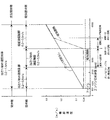
上記の考察をふまえて、図1について説明する。
まず、ダンパ手段を備えた電磁式吸排気装置のアーマチャ、バルブボディの着座速度目標値は、ダンパ手段を備えていない電磁式吸排気装置のバルブ着座速度と同等以下とする。この目標値に対して以下、その達成手段について述べる。
【0062】
ダンパ作用の特性を吸気閉弁側、吸気開弁側、排気閉弁側、排気開弁側で異なる設定とする。吸気閉弁側はエンジンの圧縮行程移行時に混合気を速やかに圧縮するため、速度一定区間が必要以上に伸びることがないようにする。このため、吸気閉弁側はエンジンの所定回転速度以上ではダンパ作用が発現しないように、ダンパピストンの戻りを制限する温度補償付きオリフィスを設ける。
【0063】
排気開弁側のダンパピストン隙間を排気閉弁側、吸気開弁側または吸気閉弁側のダンパピストン隙間よりも小さくし、ならびに/または排気開弁側のダンパピストン当たり始め位置を排気閉弁側、吸気開弁側または吸気閉弁側のダンパピストン当たり始め位置よりも近くなるようにし(ダンパストロークを大きくし)、排気筒内残圧があるときの大きなダンパピストン当たり始め速度による衝撃に耐えるようにする。ここで、図6に排気筒内残圧がある場合相当の電磁駆動部単体の着座制御結果を示す。図6からわかるように、排気筒内残圧は排気弁をバネ力により開弁させるとき、大きな抵抗となりバネの撓みとして蓄えていた位置エネルギ相当を損失させる。この損失エネルギを電磁力で補いつつ着座速度制御を行うのは非常に困難な課題である。ダンパ手段を備えた電磁式吸排気装置の場合、図6に示すように、大きなダンパピストン当たり始め速度に対し(ダンパストロークはわずかなので、ダンパピストン当たり始め速度も着座速度とほとんど同じ速度になる)、着座速度制御が可能となるようにダンパピストン隙間を小さくする。
【0064】
排気開弁側のダンパピストン隙間を排気閉弁側、吸気開弁側または吸気閉弁側のダンパピストン隙間よりも小さくし、ならびに/または排気開弁側のダンパピストン当たり始め位置を排気閉弁側、吸気開弁側または吸気閉弁側のダンパピストン当たり始め位置よりも近くなるようにすることにより、フル開弁までに長期間を要するため、フル開弁しない場合があっても許容する(フル開弁リフトを8mmとしたとき、ダンパストロークは高々100μm程度なので、エンジン性能にはほとんど影響を及ぼさない)。結果として、排気開弁側のアーマチャ着座速度は排気閉弁側、吸気開弁側または吸気閉弁側のアーマチャ着座速度よりも小さくなる。
【0065】
吸気閉弁側において、ダンパ手段による速度制御が効かなくなるエンジンの回転速度は、衝突速度吸収期間中に着座する回転速度であり、ピストンフル戻り回転速度よりも大きい回転速度になる。
【0066】
図2に示すシミュレーション結果より、速度エネルギ吸収区間の後に速度一定区間があり、この区間中に着座させることでダンパ速度制御を実現することは既に述べた通りである。これは、ダンパピストンが速度エネルギ吸収区間に必要なストローク分だけ戻ってきていれば、ダンパ速度制御が可能であるということであり、短い期間で(大きい回転速度で)実現できる。その場合、エンジンの回転速度はダンパピストン当たり始め速度に依存するので、小さい当たり始め速度にして着座速度制御に移行するようにする。ダンパストロークは高々0.1mmであるので、ダンパピストン当たり始め速度制御と同じ電圧印加時期制御の電圧オン時期で速度エネルギ吸収区間のダンパストロークが残っている区間の着座速度制御を行うことができる。
【0067】
以上説明した本発明の一実施例においては、吸気閉弁側のダンパ作用の特性が吸気開弁側、排気閉弁側または排気開弁側のダンパ作用の特性と異なっており、排気開弁側のダンパ作用の特性が排気閉弁側、吸気開弁側または吸気閉弁側のダンパ作用の特性と異なっている。このため、吸排気弁開閉時における音の発生を低減するとともに、吸気弁または排気弁の開閉タイミングをエンジンの運転条件に応じて吸気または排気が良好に行われるように制御することができ、エンジンの安定性向上、燃費の向上、あるいは排気エミッションを低減することができる。
【0068】
さらに本実施例においては、排気開弁側のダンパ作用時のダンパ力が排気閉弁側、吸気開弁側または吸気閉弁側のダンパ作用時のダンパ力よりも大きいので、排気筒内残圧があるときのダンパ作用時当初の大きい速度による衝撃にダンパ手段が耐えることができる。したがって、排気開弁時における音の発生を確実に低減することができる。
【0069】
さらにまた、本実施例においては、エンジンの所定回転速度以上において吸気閉弁側のダンパ作用が発現しないように設定されている。このため、エンジン高回転時において吸気弁を早く閉じることができ、エンジンの圧縮行程移行時に混合気を速やかに圧縮することができる。
【0070】
さらにまた、本実施例においては、ピストン150の移動速度が一定となる領域が確保されるように、ダンパ作用が発現するときのピストン150の移動速度が制御される。したがって、印加電圧の印可時期を制御することで、バルブボディ1の着座速度制御を良好に行うことができる。
【0071】
さらにまた、本実施例においては、ダンパ手段90のダンパ作用が発現するときのピストン150の移動速度から制御速度範囲を変更することなく、バルブボディ1が着座するように制御される。したがって、吸気弁を良好に制御することができる。
【0072】
以上説明した本発明の一実施例では、バルブクリアランス調整部材81のアーマチャシャフト22側の端部に螺旋状端面81aを形成したが、本発明では、バルブクリアランス調整部材のバルブボディ側の端部に螺旋状端面を形成してもよい。
【0073】
また本実施例では、ハウジング60、アーマチャ20の形状が円形のものについて説明したが、本発明では、ハウジング、アーマチャの形状が矩形であってもよい。
【0074】
また本実施例では、作動油を充填した密封容器を有するダンパ手段90を備えた電磁式吸排気装置100に本発明を適用した例について説明したが、本発明では、ダンパ手段に作動油を供給する手段、ならびにダンパ手段から作動油を排出する手段を備えたダンパ手段を備えた電磁式吸排気装置に適用することは可能である。
【図面の簡単な説明】
【図1】本発明の一実施例による電磁式吸排気装置のエンジン回転速度と吸排気弁の着座速度との関係を示すシミュレーション図である。
【図2】本発明の一実施例による電磁式吸排気装置の吸排気弁着座時のリフト量、移動速度およびダンパ手段内の流体圧力を示すシミュレーション図である。
【図3】本発明の一実施例による電磁式吸排気装置のダンパ手段を示す縦断面図である。
【図4】本発明の一実施例による電磁式吸排気装置の無通電時の状態を示す縦断面図である。
【図5】本発明の一実施例による電磁式吸排気装置の距離変更手段を示す縦断面図である。
【図6】本発明の一実施例による電磁式吸排気装置の排気開弁側のリフト量、電圧、ダンパ手段内の流体圧力、移動速度および電流を示すデータ図である。
【符号の説明】
1 バルブボディ(吸排気弁部材)
11 ステム
20 アーマチャ
21 アーマチャ本体
22 アーマチャシャフト
30 アッパコア
31 アッパコイル
41 第1のスプリング
50 ロアコア
51 ロアコイル
71 第2のスプリング
80 距離変更手段
81 バルブクリアランス調整部材
82 第3のスプリング
83 ピン
90 ダンパ手段
94、95 可動膜(可動部材、密封容器)
96 可動筒(可動部材)
100 電磁式吸排気装置
112 外輪(密封容器)
115 内輪(密封容器)
122、123 可動輪(可動部材、密封容器)
140 双方向オリフィス部材
141 双方向オリフィス(流体抵抗通路)
150 ピストン
155 スプリング(付勢手段)
158 円板(逆止弁部材)
159 一方向オリフィス部材
151 一方向オリフィス
163 摺動クリアランンス(流体抵抗通路)[0001]
BACKGROUND OF THE INVENTION
The present invention relates to an electromagnetic intake / exhaust device for driving an intake valve or an exhaust valve of an internal combustion engine (hereinafter referred to as an “internal combustion engine”) by electromagnetic force.
[0002]
[Prior art]
2. Description of the Related Art Conventionally, an electromagnetic intake / exhaust device that drives an intake valve or an exhaust valve of an engine with electromagnetic force is known. In such an electromagnetic intake / exhaust device, the opening / closing timing of the intake valve or the exhaust valve is controlled so that the intake or exhaust is satisfactorily performed according to the operating conditions of the engine, thereby improving the stability of the engine and improving the fuel efficiency. It is possible to improve or reduce exhaust emission.
[0003]
For example, since the intake air amount is small when the engine is under a low load, it is desirable that the residual exhaust gas that deteriorates combustion in the engine cylinder is small. Since the intake side is at a pressure lower than the atmospheric pressure by the throttle and the exhaust side is at a pressure higher than the atmospheric pressure during the period when the valve members of the intake valve and the exhaust valve are simultaneously open (overlap period), the exhaust gas May blow back to the intake side, causing combustion to worsen or misfire. For this reason, it is required that the timing of closing the exhaust valve is earlier than usual and the timing of opening the intake valve is later. Further, by delaying the closing timing of the intake valve, the pumping loss can be reduced and the fuel consumption can be improved. Therefore, during idle operation and start-up, it is desirable to control the basic phase so that the exhaust valve closes early and the intake valve opens late.
[0004]
In addition, the EGR amount is controlled at medium engine loads and higher, and the pumping loss is reduced by internal EGR, improving fuel efficiency and reducing exhaust emissions. It is desirable to delay the valve closing timing.
[0005]
Furthermore, since it is necessary to put a large amount of air into the engine cylinder at the full load of the engine, the intake valve is closed early in the low speed range to prevent backflow to the manifold, and the inertia of the air is increased in the high speed range. It is desirable to use and close the intake valve late. Further, on the exhaust side, it is desirable to control the exhaust valve so that the exhaust pulsation can be utilized to the maximum.
[0006]
[Problems to be solved by the invention]
The electromagnetic intake / exhaust device can satisfy the requirements of the intake side and exhaust side valve timings as described above by an instruction from an electronic control unit (ECU). However, there are many problems to be solved in terms of noise, reliability, power consumption, manufacturing cost, and the like as compared with a cam-driven valve driving device.
[0007]
In particular, it is difficult to reduce noise generated when the valve member collides with the stopper and the valve seat when the valve is opened and closed. The moving speed of the valve member of the electromagnetic intake / exhaust device is determined by the mass of the valve member, the urging force of the spring that urges the valve member, the voltage value of the applied voltage, and the application timing. If the applied voltage is not controlled, the reciprocating speed of the valve member during opening and closing is constant regardless of the engine speed, so a noise of the same magnitude as during normal operation is generated even during idle operation. You will feel noise.
[0008]
In view of this, an electromagnetic intake / exhaust device has been proposed that uses a damper means that reduces the speed at which the reciprocating member approaches both ends in the reciprocating direction, thereby reducing the generation of sound during the on-off valve. The damper means of such an electromagnetic intake / exhaust device has the following characteristics.
[0009]
(1) Reduce the speed of the reciprocating member approaching both ends in the reciprocating direction when opening and closing the intake / exhaust valve.
(2) In the damper means using fluid pressure, the reciprocating member when the intake / exhaust valve is opened / closed operates at a slight distance approaching both ends of the reciprocating direction, and the reciprocating member is locked at both ends of the reciprocating direction. In this case, a section for absorbing the speed energy and a constant speed section in which the damper force due to the fluid pressure and the external force are balanced are generated.
(3) The locking speed is fixed by locking the reciprocating member at both ends in the reciprocating direction during the constant speed section of (2) above.
[0010]
However, in the conventional electromagnetic intake / exhaust device, although the structure of the damper means has been proposed, the damper action of the damper means over the entire operation region of the engine has not been considered. In particular, when the damper action of the damper means is developed over the entire engine operating region, it may be inconvenient because it takes time to move to the next operation before the intake and exhaust valves are fully closed and fully opened in the high speed region. Although it may be possible to limit the return time of the reciprocating member by providing an orifice in the passage where the working fluid of the damper means flows, there is a case where the damper action may be effective at a high speed range, and the intake / exhaust valve control is insufficient. Met.
[0011]
The present invention has been made to solve such a problem, and provides an electromagnetic intake / exhaust device that reduces the generation of noise when the intake / exhaust valve is opened and closed, and that improves the control of the intake / exhaust valve. For the purpose.
[0012]
[Means for Solving the Problems]
According to the electromagnetic intake / exhaust device of the first aspect of the present invention, when the intake / exhaust valve member reciprocates, the damper means for reducing the speed of the intake / exhaust valve member toward both ends of the reciprocation is provided on the exhaust valve opening side. The characteristic of the damper action is different from the characteristic of the damper action on the exhaust valve closing side, intake valve opening side or intake valve closing side. Therefore, it is possible to reduce the generation of noise when the intake and exhaust valves are opened and closed, and to control the opening and closing timing of the intake valves or exhaust valves so that intake or exhaust is satisfactorily performed according to engine operating conditions. It is possible to improve the stability of the engine, improve the fuel consumption, or reduce the exhaust emission.
[0013]
Also,Claims of the invention1According to the described electromagnetic intake / exhaust device, the damper means has a larger damper force during the damper operation on the exhaust valve opening side than the damper force during the damper operation on the exhaust valve closing side, the intake valve opening side or the intake valve closing side Therefore, the damper means can withstand an impact caused by a large initial speed when the damper is operated when there is a residual pressure in the exhaust cylinder. Therefore, it is possible to reliably reduce the generation of sound when the exhaust valve is opened.
[0014]
Also,Claims of the invention1According to the electromagnetic intake / exhaust device described, when the intake / exhaust valve member approaches both ends in the reciprocating direction, the movable member moves together with the intake / exhaust valve member, so that the working fluid flows through the fluid resistance passage. Therefore, since the speed at which the intake / exhaust valve member approaches the both ends in the reciprocating direction is reduced, it is possible to reduce the noise generated when the intake / exhaust valve member is locked at both ends in the reciprocating direction.
[0015]
Further, since the working fluid is sealed in the sealed container, it is not necessary to supply the working fluid to the damper means and to discharge the working fluid from the damper means. Therefore, since the damper means can be modularized, it is easy to attach the damper means.
[0016]
Furthermore, the fluid resistance means has a smaller gap in the fluid resistance passage on the exhaust valve opening side than the fluid resistance passage on the exhaust valve closing side, the intake valve opening side or the intake valve closing side. Can be reliably reduced.
[0017]
Also,Claims of the invention1According to the electromagnetic intake / exhaust device described, the movable member has an exhaust opening position that is farther from the fully open position than the movement start position on the exhaust valve closing side, the intake valve opening side, or the intake valve closing side. The generation of sound when the valve is opened can be reliably reduced.
[0018]
Claims of the invention2According to the described electromagnetic intake / exhaust device, the intake / exhaust valve member allows the valve not to be opened to the fully open position when the rotational speed of the engine is high. Since the amount of the exhaust valve that does not fully open due to the damper means is less than 0.5% of the total valve lift, it is possible to reduce the generation of sound when the exhaust valve is opened without substantially degrading the engine performance. .
[0019]
Claims of the invention3According to the described electromagnetic intake / exhaust device, when the intake / exhaust valve member reciprocates, the damper means for reducing the speed of the intake / exhaust valve member toward both ends of the reciprocating movement has a damper action characteristic on the intake valve closing side. This is different from the damper action characteristics on the intake valve opening side, exhaust valve closing side or exhaust valve opening side. Therefore, it is possible to reduce the generation of noise when the intake and exhaust valves are opened and closed, and to control the opening and closing timing of the intake valves or exhaust valves so that intake or exhaust is satisfactorily performed according to engine operating conditions. It is possible to improve the stability of the engine, improve the fuel consumption, or reduce the exhaust emission.
[0020]
Claims of the invention4According to the described electromagnetic intake / exhaust device, the damper means is set so that the damper action on the intake valve closing side does not appear at a speed higher than the predetermined rotational speed of the engine. For this reason, the intake valve can be closed quickly at the time of high engine rotation, and the air-fuel mixture can be quickly compressed at the time of shifting to the compression stroke of the engine.
[0021]
Claims of the invention5According to the electromagnetic intake / exhaust device described, when the intake / exhaust valve member approaches both ends in the reciprocating direction, the movable member moves together with the intake / exhaust valve member, so that the working fluid flows through the fluid resistance passage. Therefore, since the speed at which the intake / exhaust valve member approaches the both ends in the reciprocating direction is reduced, it is possible to reduce the noise generated when the intake / exhaust valve member is locked at both ends in the reciprocating direction.
[0022]
Further, since the working fluid is sealed in the sealed container, it is not necessary to supply the working fluid to the damper means and to discharge the working fluid from the damper means. Therefore, since the damper means can be modularized, it is easy to attach the damper means.
[0023]
Furthermore, after the piston moves in one direction together with the movable member, the piston does not move in the opposite direction together with the movable member. The piston is urged in the opposite direction by the urging force of the urging means, and the piston tries to return to the original position when the working fluid flows through the unidirectional orifice member due to the differential pressure generated in the fluid chamber partitioned by the piston. The return speed is determined by the channel area and channel length of the unidirectional orifice if the temperature of the working fluid is the same. Therefore, the piston can be returned at a desired speed by adjusting the channel area and channel length of the unidirectional orifice. If the return speed of the piston is constant, the position where the piston returns is determined by the time until the piston starts returning and starts moving in one direction together with the movable member. This time varies depending on the reciprocating speed of the reciprocating member and the movable member. Therefore, the piston can be returned to a desired position according to the reciprocating speed of the intake / exhaust valve member and the movable member by adjusting the flow channel area and the flow channel length of the unidirectional orifice.
[0024]
Claims of the invention6According to the described electromagnetic intake / exhaust device, the damper means controls the moving speed of the piston when the damper action is exerted so as to secure a region where the moving speed of the piston is constant. Therefore, the seating speed control of the intake / exhaust valve member can be satisfactorily performed by controlling the application timing of the applied voltage.
[0025]
Claims of the invention7According to the described electromagnetic intake / exhaust device, the intake / exhaust valve member is controlled to be seated without changing the control speed range from the moving speed of the piston when the damper action of the damper means is exerted. Therefore, the intake / exhaust valve can be controlled well.
[0026]
DETAILED DESCRIPTION OF THE INVENTION
Hereinafter, examples showing embodiments of the present invention will be described with reference to the drawings.
FIG. 4 shows an electromagnetic intake / exhaust device according to an embodiment of the present invention. The electromagnetic intake /
[0027]
The
[0028]
A
[0029]
The
[0030]
As shown in FIG. 5, the distance changing means 80 changes the distance between the
[0031]
The valve
[0032]
The
[0033]
The
[0034]
The
[0035]
The
[0036]
One end portion of the
[0037]
The
[0038]
The
[0039]
The
[0040]
A
[0041]
The damper means 90 exhibits a damper function immediately before the
[0042]
A
[0043]
The
[0044]
The outer peripheral wall and the inner peripheral wall of the
[0045]
The
[0046]
A
[0047]
The
[0048]
In the
[0049]
In the
[0050]
Since the valve
[0051]
Further, the increase in the valve clearance caused by the difference in thermal expansion among the
[0052]
Next, the operation of the damper means 90 will be described.
(1) When the valve is opened, when the
[0053]
Further, when the
[0054]
Thus, when the
[0055]
(2) When the
[0056]
Further, the damping characteristic of the damper means 90 for reducing the moving speed of the
[0057]
Next, the relationship between the damper force and the external force during the damper action will be described.
The equation of motion of the armature and the pressure of the damper piston chamber can be approximately expressed by the following equations (1), (2) and (3).
m ・ d2x / dt2+ C · dx / dt + kx = −AP + FE-Ff・ ・ ・ ▲ 1 ▼
dP / dt = KA / V · dX / dt−dQ / dt ・ ・ ・ ▲ 2 ▼
dQ / dt = πhThree/ 12μL ・ (1- (e / h)2) ・ (PP0(3)
m: spring mass system mass, c: viscosity coefficient, k: spring constant, x: armature displacement
A: Damper piston area, P: Damper piston chamber pressure
dP / dt: Damper piston chamber pressure change rate, FE: Electromagnetic force, Ff: Dry friction force
K: Volumetric elastic modulus of damper piston chamber hydraulic oil, V: Damper piston chamber volume
dQ / dt: leakage flow rate from the damper piston gap, h: damper piston gap
μ: Viscosity of damper piston chamber hydraulic oil, L: Damper piston seal length
e: Eccentricity, P0:Atmospheric pressure
Here, the formulas (2) and (3) are established after the damper piston abuts.
[0058]
A simulation of the electromagnetic intake / exhaust device provided with the damper means can be constructed using the above formulas (1), (2) and (3).
Here, the lift amount, armature speed, and damper piston chamber pressure when the armature is seated during the damper operation will be described using the simulation results shown in FIG. FIG. 2 shows the initial speed per damper piston of 0.6 m / s and 0.2 m / s. The simulation is started from the state where the valve body is kept in the open position. At this time, when the hold current that keeps the valve body in the open position is turned off, the electromagnetic force is attenuated with the disappearance of the eddy current generated in the armature and the lower core, and the damping motion of the spring mass system starts. When the armature passes the neutral position, a voltage is applied to the upper coil in order to generate an electromagnetic force for attracting the valve body to the closed position. The armature is lifted by the catch current and catch electromagnetic force generated by the applied voltage and displaced more than the damping motion locus of the spring mass system, and the energy of the spring mass system increases to the speed at which it collides with the upper core. It is all electronic control that accurately controls this increased energy and makes it sit without failure at a speed of several cm / s. In addition, the damper control is caused to collide with the damper means at a higher speed and to sit without failure at a speed of several cm / s by using the energy absorbing power of the damper means.
[0059]
The following can be said from the simulation results shown in FIG.
a. The higher the starting speed per damper piston, the longer the damper stroke required for the speed energy absorption section and the shorter the constant speed stroke.
b. The higher the starting speed per damper piston, the shorter the time from when the hold current is turned off until it is seated.
c. The engine speed at which the speed control by the damper means becomes ineffective is the rotational speed at which the engine is seated during the speed energy absorption section (if the starting speed is too high, the engine is seated before absorbing the speed energy).
[0060]
Further, from the above-described equations (1), (2) and (3) and the simulation result shown in FIG.
In the constant speed section shown in FIG. 2, the speed energy absorption section ends, and the inertia term m · d2x / dt2Becomes smaller (term c · dx / dt, FfIs negligibly small), kx = −AP + FEThe damper piston chamber pressure P determined by the relationship Since x does not fluctuate greatly at the position where the damper action is effective, it may be considered to be almost constant, and P = 1 / A · (kx−FE) Damper piston chamber pressure P is electromagnetic force FEIs gradually increased in response to a change due to a slight displacement of the lift amount x of the armature. Because of this pressure P, the leakage flow rate dQ / dt from the damper piston gap is determined from the equation (3), so in the equation (2), dQ / dt = 0,
V = dx / dt
= V / KA · dQ / dt
= ΠVhThree/ 12μLKA
And
d. The armature moving speed is proportional to the third power of the piston clearance.
[0061]
Based on the above consideration, FIG. 1 will be described.
First, the seating speed target value of the electromagnetic intake / exhaust device provided with the damper means is set to be equal to or less than the valve seating speed of the electromagnetic intake / exhaust device not provided with the damper means. The means for achieving the target value will be described below.
[0062]
The damper action characteristics are set differently on the intake valve closing side, the intake valve opening side, the exhaust valve closing side, and the exhaust valve opening side. The intake valve closing side quickly compresses the air-fuel mixture at the time of transition to the compression stroke of the engine, so that the constant speed section is not extended more than necessary. For this reason, the intake valve closing side is provided with a temperature-compensated orifice for restricting the return of the damper piston so that the damper action does not appear at a predetermined rotational speed of the engine or higher.
[0063]
The damper piston gap on the exhaust valve opening side is made smaller than the damper piston gap on the exhaust valve closing side, intake valve opening side or intake valve closing side, and / or the start position of the damper valve on the exhaust valve opening side is the exhaust valve closing side In order to withstand the impact caused by the large starting speed per damper piston when there is a residual pressure in the exhaust cylinder, it should be closer to the starting position of the damper piston on the intake valve opening side or the intake valve closing side. To. Here, FIG. 6 shows the seating control result of the electromagnetic drive unit corresponding to the case where there is a residual pressure in the exhaust cylinder. As can be seen from FIG. 6, the exhaust cylinder residual pressure becomes a large resistance when the exhaust valve is opened by the spring force, and the potential energy stored as the spring deflection is lost. It is a very difficult task to control the seating speed while compensating for this loss energy with electromagnetic force. In the case of an electromagnetic intake / exhaust device having a damper means, as shown in FIG. 6, with respect to a large starting speed per damper piston (since the damper stroke is small, the starting speed per damper piston is almost the same as the seating speed). The damper piston clearance is reduced so that the seating speed can be controlled.
[0064]
The damper piston gap on the exhaust valve opening side is made smaller than the damper piston gap on the exhaust valve closing side, intake valve opening side or intake valve closing side, and / or the start position of the damper valve on the exhaust valve opening side is the exhaust valve closing side Because it takes a long time to fully open the valve by making it closer to the starting position of the damper piston on the intake valve opening side or intake valve closing side, even if the valve is not fully open, it is allowed (full When the valve lift is 8 mm, the damper stroke is at most 100 μm, so it has little effect on the engine performance). As a result, the armature seating speed on the exhaust valve opening side is smaller than the armature seating speed on the exhaust valve closing side, the intake valve opening side, or the intake valve closing side.
[0065]
On the intake valve closing side, the rotational speed of the engine at which the speed control by the damper means is not effective is the rotational speed at which the engine is seated during the collision speed absorption period, and is larger than the piston full return rotational speed.
[0066]
From the simulation results shown in FIG. 2, there is a constant speed section after the speed energy absorption section, and as described above, the damper speed control is realized by being seated in this section. This means that the damper speed can be controlled if the damper piston returns by the necessary stroke in the speed energy absorption section, and this can be realized in a short period (at a high rotational speed). In this case, since the rotational speed of the engine depends on the starting speed per damper piston, the seating speed control is shifted to a small starting speed. Since the damper stroke is at most 0.1 mm, it is possible to perform the seating speed control in the section where the damper stroke of the speed energy absorption section remains at the voltage-on timing of the same voltage application timing control as the start speed control per damper piston.
[0067]
In the embodiment of the present invention described above, the damper action characteristic on the intake valve closing side is different from the damper action characteristic on the intake valve opening side, the exhaust valve closing side or the exhaust valve opening side, and the exhaust valve opening side The characteristic of the damper action is different from the characteristic of the damper action on the exhaust valve closing side, intake valve opening side or intake valve closing side. Therefore, it is possible to reduce the generation of noise when the intake and exhaust valves are opened and closed, and to control the opening and closing timing of the intake valves or exhaust valves so that intake or exhaust is satisfactorily performed according to engine operating conditions. It is possible to improve the stability of the engine, improve the fuel consumption, or reduce the exhaust emission.
[0068]
Furthermore, in this embodiment, the damper force at the time of the exhaust valve opening side damper operation is larger than the damper force at the time of exhaust valve closing side, intake valve opening side or intake valve closing side damper operation, so that the exhaust cylinder residual pressure When there is a damper, the damper means can withstand the impact caused by the initial large speed. Therefore, it is possible to reliably reduce the generation of sound when the exhaust valve is opened.
[0069]
Furthermore, in this embodiment, it is set so that the damper action on the intake valve closing side does not appear above the predetermined rotational speed of the engine. For this reason, the intake valve can be closed quickly at the time of high engine rotation, and the air-fuel mixture can be quickly compressed at the time of shifting to the compression stroke of the engine.
[0070]
Furthermore, in this embodiment, the moving speed of the
[0071]
Furthermore, in this embodiment, the
[0072]
In the embodiment of the present invention described above, the
[0073]
In this embodiment, the
[0074]
In the present embodiment, the example in which the present invention is applied to the electromagnetic intake /
[Brief description of the drawings]
FIG. 1 is a simulation diagram showing the relationship between the engine speed of an electromagnetic intake / exhaust device according to an embodiment of the present invention and the seating speed of an intake / exhaust valve.
FIG. 2 is a simulation diagram showing a lift amount, a moving speed, and a fluid pressure in a damper means when an intake / exhaust valve is seated in an electromagnetic intake / exhaust device according to an embodiment of the present invention.
FIG. 3 is a longitudinal sectional view showing damper means of an electromagnetic intake / exhaust device according to an embodiment of the present invention.
FIG. 4 is a longitudinal sectional view showing a state of the electromagnetic intake / exhaust device according to one embodiment of the present invention when no power is supplied.
FIG. 5 is a longitudinal sectional view showing distance changing means of an electromagnetic intake / exhaust device according to an embodiment of the present invention.
FIG. 6 is a data diagram showing lift amount, voltage, fluid pressure in the damper means, moving speed, and current on the exhaust valve opening side of the electromagnetic intake / exhaust device according to one embodiment of the present invention.
[Explanation of symbols]
1 Valve body (intake / exhaust valve member)
11 stem
20 Armature
21 Armature body
22 Armature shaft
30 Upper core
31 Upper coil
41 First spring
50 lower core
51 Lower coil
71 Second spring
80 Distance change means
81 Valve clearance adjustment member
82 Third spring
83 pins
90 Damper means
94, 95 Movable membrane (movable member, sealed container)
96 Movable cylinder (movable member)
100 Electromagnetic intake / exhaust system
112 Outer ring (sealed container)
115 Inner ring (sealed container)
122, 123 Movable wheels (movable members, sealed containers)
140 Bidirectional Orifice Member
141 Bidirectional orifice (fluid resistance passage)
150 piston
155 Spring (biasing means)
158 Disc (check valve member)
159 Unidirectional orifice member
151 Unidirectional orifice
163 Sliding Clearance (fluid resistance passage)
Claims (7)
前記吸排気弁部材を駆動する電磁駆動部と、
前記吸排気弁部材が往復移動するとき、往復移動の両終端に向かう前記吸排気弁部材の速度を低減するダンパ手段とを備え、
前記ダンパ手段は、排気開弁側のダンパ作用の特性が排気閉弁側、吸気開弁側または吸気閉弁側のダンパ作用の特性と異なっており、
前記ダンパ手段は、排気開弁側のダンパ作用時のダンパ力が排気閉弁側、吸気開弁側または吸気閉弁側のダンパ作用時のダンパ力よりも大きく、
前記ダンパ手段は、
作動流体を密封している密封容器と、
前記吸排気弁部材が往復移動方向の両終端に近づくとき前記吸排気弁部材とともに移動することにより、前記密封容器内の作動流体を移動させる可動部材と、
前記密封容器内の作動流体が流れる流体抵抗通路を有し、前記可動部材が前記往復移動部材とともに移動することにより作動流体が前記流体抵抗通路を流れる流体抵抗手段とを備え、
前記流体抵抗手段は、排気開弁側の前記流体抵抗通路の間隙が排気閉弁側、吸気開弁側または吸気閉弁側の前記流体抵抗通路の間隙よりも小さく、
前記可動部材は、排気開弁側の移動開始位置が排気閉弁側、吸気開弁側または吸気閉弁側の移動開始位置よりも全開位置から遠いことを特徴とする電磁式吸排気装置。 An intake and exhaust valve member for intermittently connecting the intake passage or the exhaust passage of the internal combustion engine and the combustion chamber by reciprocating;
An electromagnetic drive unit for driving the intake / exhaust valve member;
Damper means for reducing the speed of the intake and exhaust valve members toward both ends of the reciprocation when the intake and exhaust valve members reciprocate;
The damper means has a damper action characteristic on the exhaust valve opening side that is different from a damper action characteristic on the exhaust valve closing side, the intake valve opening side or the intake valve closing side ,
The damper means is such that the damper force at the time of the damper action on the exhaust valve opening side is larger than the damper force at the time of the damper action on the exhaust valve closing side, the intake valve opening side or the intake valve closing side,
The damper means is
A sealed container that seals the working fluid;
A movable member that moves the working fluid in the sealed container by moving together with the intake / exhaust valve member when the intake / exhaust valve member approaches both ends in the reciprocating direction;
A fluid resistance passage through which the working fluid in the sealed container flows, and fluid resistance means in which the working fluid flows through the fluid resistance passage when the movable member moves together with the reciprocating member.
In the fluid resistance means, the gap of the fluid resistance passage on the exhaust valve opening side is smaller than the gap of the fluid resistance passage on the exhaust valve closing side, intake valve opening side or intake valve closing side,
The electromagnetic intake / exhaust device, wherein the movable member has a movement start position on the exhaust valve opening side that is farther from a fully open position than a movement start position on the exhaust valve closing side, the intake valve opening side, or the intake valve closing side.
前記吸排気弁部材を駆動する電磁駆動部と、An electromagnetic drive unit for driving the intake / exhaust valve member;
前記吸排気弁部材が往復移動するとき、往復移動の両終端に向かう前記吸排気弁部材の速度を低減するダンパ手段とを備え、Damper means for reducing the speed of the intake and exhaust valve members toward both ends of the reciprocation when the intake and exhaust valve members reciprocate;
前記ダンパ手段は、吸気閉弁側のダンパ作用の特性が吸気開弁側、排気閉弁側または排気開弁側のダンパ作用の特性と異なっていることを特徴とする電磁式吸排気装置。The damper means is characterized in that the damper action characteristic on the intake valve closing side is different from the damper action characteristic on the intake valve opening side, exhaust valve closing side or exhaust valve opening side.
作動流体を密封している密封容器と、
前記吸排気弁部材が往復移動方向の両終端に近づくとき前記吸排気弁部材とともに移動することにより、前記密封容器内の作動流体を移動させる可動部材と、
前記密封容器内の作動流体が流れる流体抵抗通路を有し、前記可動部材が前記往復移動部材とともに移動することにより作動流体が前記流体抵抗通路を流れる流体抵抗手段と、
前記可動部材とともに一方向に移動するピストンと、
前記密封容器内に収容され、前記ピストンを往復移動自在に支持し、前記可動部材とともに前記ピストンが一方向に移動する側が閉塞されているシリンダと、
前記ピストンが前記可動部材とともに一方向に移動する方向と反対方向に前記ピストンを付勢する付勢手段と、
前記ピストンを軸方向に貫通する貫通孔に取り付けられ、一方向オリフィスを有する一方向オリフィス部材と、
前記付勢手段により前記一方向オリフィス部材に向けて付勢され、作動流体が前記付勢手段の付勢方向に前記一方向オリフィスを流れることを防止する逆止弁部材と、
を備えることを特徴とする請求項4記載の電磁式吸排気装置。 The damper means is
A sealed container that seals the working fluid;
A movable member that moves the working fluid in the sealed container by moving together with the intake / exhaust valve member when the intake / exhaust valve member approaches both ends in the reciprocating direction;
A fluid resistance passage through which the working fluid in the sealed container flows, and a fluid resistance means in which the working fluid flows through the fluid resistance passage when the movable member moves together with the reciprocating member;
A piston that moves in one direction with the movable member ;
A cylinder which is housed in the sealed container, supports the piston so as to be reciprocally movable, and is closed on the side where the piston moves in one direction together with the movable member;
A biasing means for biasing the piston in a direction opposite to a direction in which the piston moves in one direction together with the movable member;
A one-way orifice member attached to a through-hole penetrating the piston in the axial direction and having a one-way orifice;
A check valve member that is biased by the biasing means toward the one-way orifice member and prevents the working fluid from flowing through the one-way orifice in the biasing direction of the biasing means;
The electromagnetic intake / exhaust device according to claim 4, further comprising:
Priority Applications (1)
| Application Number | Priority Date | Filing Date | Title |
|---|---|---|---|
| JP2000048598A JP4147568B2 (en) | 2000-02-25 | 2000-02-25 | Electromagnetic intake / exhaust system |
Applications Claiming Priority (1)
| Application Number | Priority Date | Filing Date | Title |
|---|---|---|---|
| JP2000048598A JP4147568B2 (en) | 2000-02-25 | 2000-02-25 | Electromagnetic intake / exhaust system |
Publications (2)
| Publication Number | Publication Date |
|---|---|
| JP2001234718A JP2001234718A (en) | 2001-08-31 |
| JP4147568B2 true JP4147568B2 (en) | 2008-09-10 |
Family
ID=18570665
Family Applications (1)
| Application Number | Title | Priority Date | Filing Date |
|---|---|---|---|
| JP2000048598A Expired - Fee Related JP4147568B2 (en) | 2000-02-25 | 2000-02-25 | Electromagnetic intake / exhaust system |
Country Status (1)
| Country | Link |
|---|---|
| JP (1) | JP4147568B2 (en) |
Families Citing this family (4)
| Publication number | Priority date | Publication date | Assignee | Title |
|---|---|---|---|---|
| KR100411120B1 (en) * | 2001-09-11 | 2003-12-18 | 현대자동차주식회사 | Oil control valve |
| CN109026633A (en) * | 2018-09-30 | 2018-12-18 | 海南汉地阳光石油化工有限公司 | A kind of compressor air-discharging quantity regulating device |
| CN111810701B (en) * | 2020-04-24 | 2021-11-05 | 浙江工业大学 | Method for realizing variable dynamic characteristics of electromagnetic valve at each stage by switching multiple voltage sources |
| CN111664288B (en) * | 2020-06-01 | 2021-11-30 | 浙江工业大学 | Method for considering both opening and closing dynamic characteristics and opening and closing buffer characteristics of high-speed switch valve |
-
2000
- 2000-02-25 JP JP2000048598A patent/JP4147568B2/en not_active Expired - Fee Related
Also Published As
| Publication number | Publication date |
|---|---|
| JP2001234718A (en) | 2001-08-31 |
Similar Documents
| Publication | Publication Date | Title |
|---|---|---|
| US7984701B2 (en) | Device for controlling the movement of a valve, in particular of an intake valve, of an internal combustion engine | |
| JPS6138323B2 (en) | ||
| US20100224156A1 (en) | Reciprocable member with anti-float arrangement | |
| JP4147568B2 (en) | Electromagnetic intake / exhaust system | |
| JPH0534484B2 (en) | ||
| JPH11508345A (en) | Fuel pump and operating method thereof | |
| JP4186141B2 (en) | Damper device and electromagnetic intake / exhaust device using the same | |
| JP2002285807A (en) | Lash adjuster | |
| US20040238773A1 (en) | Controlled leakage hydraulic damper | |
| JP2007182841A (en) | Valve driving device | |
| JP4134467B2 (en) | Valve drive device | |
| JP4968180B2 (en) | Injector | |
| JP2022517119A (en) | Engine valve mechanism parts that selectively reset lost motion | |
| JP2007205302A (en) | Intake air control device for engine | |
| JPH057451Y2 (en) | ||
| JP4378877B2 (en) | Hydraulic control valve and fuel injection valve | |
| US6817324B2 (en) | Control unit of electromagnetically driven valve and control method thereof | |
| JP2001132420A (en) | Valve system for internal combustion engine | |
| JP3796935B2 (en) | Fuel injection valve | |
| JP4378878B2 (en) | Hydraulic control valve and fuel injection valve | |
| JP4140184B2 (en) | Fuel injection device | |
| JPH04287814A (en) | Valve system of engine | |
| JPH11229833A (en) | Electromagnetic drive valve | |
| JP4120229B2 (en) | Solenoid valve | |
| JPH04171208A (en) | Hydraulic-actuation valve unit |
Legal Events
| Date | Code | Title | Description |
|---|---|---|---|
| A621 | Written request for application examination |
Free format text: JAPANESE INTERMEDIATE CODE: A621 Effective date: 20060207 |
|
| A977 | Report on retrieval |
Free format text: JAPANESE INTERMEDIATE CODE: A971007 Effective date: 20080303 |
|
| A131 | Notification of reasons for refusal |
Free format text: JAPANESE INTERMEDIATE CODE: A131 Effective date: 20080303 |
|
| A521 | Written amendment |
Free format text: JAPANESE INTERMEDIATE CODE: A523 Effective date: 20080425 |
|
| TRDD | Decision of grant or rejection written | ||
| A01 | Written decision to grant a patent or to grant a registration (utility model) |
Free format text: JAPANESE INTERMEDIATE CODE: A01 Effective date: 20080602 |
|
| A01 | Written decision to grant a patent or to grant a registration (utility model) |
Free format text: JAPANESE INTERMEDIATE CODE: A01 |
|
| A61 | First payment of annual fees (during grant procedure) |
Free format text: JAPANESE INTERMEDIATE CODE: A61 Effective date: 20080615 |
|
| FPAY | Renewal fee payment (event date is renewal date of database) |
Free format text: PAYMENT UNTIL: 20110704 Year of fee payment: 3 |
|
| R150 | Certificate of patent or registration of utility model |
Free format text: JAPANESE INTERMEDIATE CODE: R150 |
|
| LAPS | Cancellation because of no payment of annual fees |