JP4146017B2 - Near-field optical head - Google Patents
Near-field optical head Download PDFInfo
- Publication number
- JP4146017B2 JP4146017B2 JP00035499A JP35499A JP4146017B2 JP 4146017 B2 JP4146017 B2 JP 4146017B2 JP 00035499 A JP00035499 A JP 00035499A JP 35499 A JP35499 A JP 35499A JP 4146017 B2 JP4146017 B2 JP 4146017B2
- Authority
- JP
- Japan
- Prior art keywords
- recording medium
- slider
- minute
- optical head
- field optical
- Prior art date
- Legal status (The legal status is an assumption and is not a legal conclusion. Google has not performed a legal analysis and makes no representation as to the accuracy of the status listed.)
- Expired - Fee Related
Links
Images


Classifications
-
- G—PHYSICS
- G11—INFORMATION STORAGE
- G11B—INFORMATION STORAGE BASED ON RELATIVE MOVEMENT BETWEEN RECORD CARRIER AND TRANSDUCER
- G11B7/00—Recording or reproducing by optical means, e.g. recording using a thermal beam of optical radiation by modifying optical properties or the physical structure, reproducing using an optical beam at lower power by sensing optical properties; Record carriers therefor
- G11B7/12—Heads, e.g. forming of the optical beam spot or modulation of the optical beam
- G11B7/122—Flying-type heads, e.g. analogous to Winchester type in magnetic recording
-
- B—PERFORMING OPERATIONS; TRANSPORTING
- B82—NANOTECHNOLOGY
- B82Y—SPECIFIC USES OR APPLICATIONS OF NANOSTRUCTURES; MEASUREMENT OR ANALYSIS OF NANOSTRUCTURES; MANUFACTURE OR TREATMENT OF NANOSTRUCTURES
- B82Y10/00—Nanotechnology for information processing, storage or transmission, e.g. quantum computing or single electron logic
-
- Y—GENERAL TAGGING OF NEW TECHNOLOGICAL DEVELOPMENTS; GENERAL TAGGING OF CROSS-SECTIONAL TECHNOLOGIES SPANNING OVER SEVERAL SECTIONS OF THE IPC; TECHNICAL SUBJECTS COVERED BY FORMER USPC CROSS-REFERENCE ART COLLECTIONS [XRACs] AND DIGESTS
- Y10—TECHNICAL SUBJECTS COVERED BY FORMER USPC
- Y10S—TECHNICAL SUBJECTS COVERED BY FORMER USPC CROSS-REFERENCE ART COLLECTIONS [XRACs] AND DIGESTS
- Y10S977/00—Nanotechnology
- Y10S977/84—Manufacture, treatment, or detection of nanostructure
- Y10S977/849—Manufacture, treatment, or detection of nanostructure with scanning probe
- Y10S977/86—Scanning probe structure
- Y10S977/862—Near-field probe
-
- Y—GENERAL TAGGING OF NEW TECHNOLOGICAL DEVELOPMENTS; GENERAL TAGGING OF CROSS-SECTIONAL TECHNOLOGIES SPANNING OVER SEVERAL SECTIONS OF THE IPC; TECHNICAL SUBJECTS COVERED BY FORMER USPC CROSS-REFERENCE ART COLLECTIONS [XRACs] AND DIGESTS
- Y10—TECHNICAL SUBJECTS COVERED BY FORMER USPC
- Y10S—TECHNICAL SUBJECTS COVERED BY FORMER USPC CROSS-REFERENCE ART COLLECTIONS [XRACs] AND DIGESTS
- Y10S977/00—Nanotechnology
- Y10S977/84—Manufacture, treatment, or detection of nanostructure
- Y10S977/849—Manufacture, treatment, or detection of nanostructure with scanning probe
- Y10S977/86—Scanning probe structure
- Y10S977/873—Tip holder
Landscapes
- Physics & Mathematics (AREA)
- Optics & Photonics (AREA)
- Optical Head (AREA)
Abstract
Description
【0001】
【発明の属する技術分野】
この発明は、近視野光学ヘッドに関し、より詳しくは、近視野顕微鏡技術をハードディスクなどに代表される記録装置のヘッドに適用した近視野光学ヘッドに関する。
【0002】
【従来の技術】
近視野光を利用する光プローブを備えた近視野顕微鏡では、光の回折限界以上の高分解能にて試料を観測することができる。このような近視野顕微鏡では、当該光プローブの試料対向端部として、先鋭化した光ファイバー先端に設けた微小開口や異方性エッチングを施して形成されたシリコン基板上のチップに設けた微小開口を用いたり、光ファイバーの先鋭化された先端や当該チップによる微小突起を用いている。
【0003】
一方、このような観測原理を応用した、例えば(E. Betzig et al., Science 257,189(1992))に開示されているような近接場光学メモリも提案されている。このような応用例においては、記録または読取ヘッドに形成される微小開口または微小突起を記録媒体表面に伝搬光である照射光の波長以下に近接または当接させる必要がある。
【0004】
近接場光学メモリの記録/読取システムにおける多くの場合、ディスク状の記録媒体を回転させ、その表面をヘッドにより走査している。このため、記録媒体の回転に伴い、主面の面内方向(主面に平行な方向)および面外方向(主面に垂直な方向)に振動が発生する。記録/読取システムでは、ヘッドと被検出表面とを近接させる必要があるため、前記面外方向の振動が重要になる。面外方向の振動は、主に記録媒体主面の平面度、記録媒体と回転軸との取り付け精度、および回転軸の軸受け精度に起因する。一方、ヘッド側では、微小開口や微小突起を前記記録媒体の面外方向の振動に追従させる必要がある。
【0005】
一般的に、近接場光学メモリの記録/読取システムでは、微小開口または微小突起を有するカンチレバー構造を採るヘッドが用いられ、当該ヘッドをコンタクトAFM(原子力間力顕微鏡:Atomic Force Microscope )で動作させる場合には当該カンチレバーの撓みを、または、前記ヘッドをサイクリックコンタクト或いはシェアフォースにて動作させる場合にはその振動数、振幅および振動の位相などの変化を検出する距離検出機構が必要になる。さらに、その検出信号をフィードバックするフィードバック回路と、このフィードバック信号に基づいてカンチレバーと記録媒体との間隔を能動的に変化させる距離変位機構とが必要となる。
【0006】
【発明が解決しようとする課題】
しかしながら、上記従来の近接場光学メモリの記録/読取システムでは、距離検出機構、フィードバック回路および距離変位機構を必要とするため、構成が複雑化するという問題点があった。
【0007】
そこで、この発明は、上記に鑑みてなされたものであって、簡単な構造でしかも記録媒体とヘッドとの距離制御を簡略化できる近視野光学ヘッドを提供することを目的とする。
【0008】
【課題を解決するための手段】
上述の目的を達成するために、請求項1に係る近視野光学ヘッドは、負荷加重を与えるサスペンションアームにより支持されると共に記録媒体との相対運動により浮上力を得、前記負荷加重と前記浮上力との均衡により記録媒体との間に隙間をつくるスライダーと、当該スライダーから延出し、その端部に微小突起または微小開口を有するカンチレバーと、を備え、前記スライダーが浮上して傾くことで、前記微小突起または微小開口を前記記録媒体に接触させるものである。
【0009】
この近視野光学ヘッドは、浮上型ヘッド機構を用いるので、記録媒体に対する能動的な距離制御機構が不要になる。また、近視野光を利用することで光の回折限界以上の分解能が得られること、微小突起や微小開口を記録媒体にコンタクトさせる方式を採用していること、から微細なデータの録再が可能になり、データの転送速度が向上する。
【0010】
また、請求項2に係る近視野光学ヘッドは、負荷加重を与えるサスペンションアームにより支持されると共に記録媒体との相対運動により浮上力を得、前記負荷加重と前記浮上力との均衡により記録媒体との間に隙間をつくるスライダーと、微小突起または微小開口を有し、前記スライダーが記録媒体に接触状態にあるときは前記微小突起または微小開口が記録媒体に非接触状態になるように前記スライダーから延出したカンチレバーと、を備え、前記スライダーが浮上して傾いたとき、前記微小突起または微小開口が前記記録媒体に接触するものである。
【0011】
この近視野光学ヘッドは、浮上型ヘッド機構を用いるので、記録媒体に対する能動的な距離制御機構が不要になる。また、近視野光を利用することで光の回折限界以上の分解能が得られること、微小突起や微小開口を記録媒体にコンタクトさせる方式を採用していること、から微細なデータの録再が可能になり、データの転送速度が向上する。さらに、スライダーが浮上したときにのみ、微小突起または微小開口が記録媒体に接触し、静止状態では非接触になるので、微小突起または微小開口を有効に保護できる。
【0012】
また、請求項3に係る近視野光学ヘッドは、負荷加重を与えるサスペンションアームにより支持されると共に記録媒体との相対運動により浮上力を得、前記負荷加重と前記浮上力との均衡により記録媒体との間に隙間をつくるスライダーと、端部に微小突起または微小開口を有し、スライダーから延出すると共に前記微小突起または微小開口とスライダー底面との間に高低差を設けたカンチレバーと、を備え、前記スライダーが浮上して傾いたとき、前記微小突起または微小開口が前記記録媒体に接触するものである。
【0013】
この近視野光学ヘッドは、浮上型ヘッド機構を用いるので、記録媒体に対する能動的な距離制御機構が不要になる。また、近視野光を利用することで光の回折限界以上の分解能が得られること、微小突起や微小開口を記録媒体にコンタクトさせる方式を採用していること、から微細なデータの録再が可能になり、データの転送速度が向上する。さらに、前記微小突起または微小開口とスライダー底面との間に高低差を設けることにより、スライダーが浮上したときにのみ、微小突起または微小開口が記録媒体に接触するようになる。このため、微小突起または微小開口を有効に保護できる。
また、請求項4に係る近視野光学ヘッドは、負荷加重を与えるサスペンションアームにより支持されると共に記録媒体との相対運動により浮上力を得、前記負荷加重と前記浮上力との均衡により記録媒体との間に隙間をつくるスライダーと、当該スライダーから延出し、その端部に微小突起または微小開口を有するカンチレバーと、前記スライダーを前記記録媒体に対して垂直方向に移動させる移動機構と、を備え、前記移動機構により前記スライダーが前記記録媒体に接近して浮上したとき、前記微小突起または微小開口が前記記録媒体に接触するものである。
この近視野光学ヘッドは、浮上型ヘッド機構を用いるので、記録媒体に対する能動的な距離制御機構が不要になる。また、近視野光を利用することで光の回折限界以上の分解能が得られること、微小突起や微小開口を記録媒体にコンタクトさせる方式を採用していること、から微細なデータの録再が可能になり、データの転送速度が向上する。
また、請求項5に係る近視野光学ヘッドは、負荷加重を与えるサスペンションアームにより支持されると共に記録媒体との相対運動により浮上力を得、前記負荷加重と前記浮上力との均衡により記録媒体との間に隙間をつくるスライダーと、前記スライダーを前記記録媒体に対して垂直方向に移動させる移動機構と、微小突起または微小開口を有し、前記スライダーが記録媒体から離れた状態にあるときは前記微小突起または微小開口が記録媒体に非接触状態になるように前記スライダーから延出したカンチレバーと、を備え、前記スライダーが前記記録媒体に接近して浮上したとき、前記微小突起または微小開口が前記記録媒体に接触することを特徴とする近視野光学ヘッド。
この近視野光学ヘッドは、浮上型ヘッド機構を用いるので、記録媒体に対する能動的な距離制御機構が不要になる。また、近視野光を利用することで光の回折限界以上の分解能が得られること、微小突起や微小開口を記録媒体にコンタクトさせる方式を採用していること、から微細なデータの録再が可能になり、データの転送速度が向上する。さらに、スライダーが浮上したときにのみ、微小突起または微小開口が記録媒体に接触し、その他の状態では非接触になるので、微小突起または微小開口を有効に保護できる。
【0014】
また、請求項6に係る近視野光学ヘッドは、上記近視野光学ヘッドにおいて、前記微小開口を、カンチレバーの端部に設けたコンタクトパッドに形成したものである。
【0015】
現在、スライダー底面にコンタクトパットを設けて行うコンタクト方式が知られており(跳躍をしたときでも最大10nmの浮上量が得られる)、この発明は、このコンタクトパットに微小開口を形成したものである。特に、チップ先端とスライダー底面との高さ合わせが困難なときに有効な構成となる。また、コンタクトパット程度の大きさならば、チップが破壊しにくくなる。また、記録媒体との吸着が少なくなる。
【0016】
また、請求項7に係る近視野光学ヘッドは、上記近視野光学ヘッドにおいて、前記微小突起または微小開口を複数設け、分光器を用いて照射光を分光し、当該分光光を前記各微小突起または微小開口に対応する記録媒体部分に照射するようにしたものである。
【0017】
このように、分光器を用いて照射光を分光すれば、単一の光源でマルチ化できる。このため、ヘッドサイズをコンパクトにできる。
【0018】
【発明の実施の形態】
以下、この発明につき図面を参照しつつ詳細に説明する。なお、この実施の形態によりこの発明が限定されるものではない。
【0019】
(実施の形態1)
図1は、この発明の実施の形態1による近視野光学ヘッドを示す概略構成図である。より詳しくは、記録媒体の断面構造とともに当該記録媒体にアクセスする際の姿勢を示すものである。スライダー1は、サスペンションアーム(図示省略)により支持される。これらサスペンションアームとスライダー1とによって浮上ヘッド機構が構成される。サスペンションアームは、ボイスコイルモータ(図示省略)を駆動源とし揺動軸を中心に揺動する。スライダー1の走査方位には、テーパ1aが設けてある。このテーパ1aとスライダー底面1bおよび記録媒体4の表面とにより、くさび膜形状の流路1cを形成する。スライダー1には、サスペンションアームおよびジンバルバネにより、記録媒体4側への負荷加重が与えられている。スライダー1は、シーク制御およびフォローイング制御により記録媒体4のトラック上に位置決めされている。
【0020】
カンチレバー2は、スライダー1から走査方向に沿って延出している。また、カンチレバー2はその先端にチップ3を有する。チップ3は、先鋭化処理によってくびれたように鋭くなっている。このため、カンチレバー2が記録媒体4に吸着しにくい。また、チップ3とスライダー底面1bとの間には、高低差がある。カンチレバー2は、Siプロセスによりスライダー1と一体成形する。Siプロセスにより一体成形すれば、スライダー底面1bとチップ3との高さを精密に制御できる。このため、非常に先鋭なチップ3であってもその先端を破壊することがない。
【0021】
記録媒体4の表面には、ビット9が形成されている。記録媒体4の裏面には、光源(図示省略)が配置されている。なお、本例では全反射によるコレクションの場合を示したが、全反射を用いない場合(暗視野照明など)や、イルミネーションでも良い。また、カンチレバー2上方には、集光レンズ5と受光素子6とが配置してある。受光素子6は、光電変換した信号を処理する信号処理系(図示省略)に接続されている。
【0022】
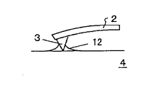
つぎに、この近視野光学ヘッド100の動作について説明する。記録媒体4が回転していないときは、スライダー1が浮上せず記録媒体4に接地している。この状態では、図2に示すように、カンチレバー2が記録媒体4にコンタクトすることはない。つぎに、記録媒体4が回転することにより記録媒体4表面上の空気10がくさび膜形状の流路1cに押し込まれると、当該流路1cに圧力が発生してスライダー1が浮上する。一方、スライダー1には、サスペンションアームによって負荷加重が与えられている。この負荷加重と前記浮上圧力が均衡して、スライダー1と記録媒体4との間に流路1cが生じる。スライダー1は傾いて浮上するから、カンチレバー2のチップ3が記録媒体4にコンタクトする。コンタクトは、図3に示すように記録媒体4に押し付けた状態でも、図4に示すように記録媒体表面4の吸着層12により引きつけられている状態でもよい。但し、押し付けている場合は、その荷重は少ない方がよい。
【0023】
記録媒体4の表面には、光源による光7の照射によって近視野光が発生している。スライダー1が浮上してカンチレバー2のチップ3が記録媒体4にコンタクトすると、近視野光が散乱し伝搬光11が発生する。この伝搬光11は、集光レンズ5によって集光され、受光素子6により受光される。伝搬光11の強度その他の状態はビット9の有無により変化するため、これに従い、光電変換した信号の強度が変化する。信号処理系では、信号強度をデータ変換して記録媒体上の情報を再生する。
【0024】
なお、カンチレバー2の長さや厚さ(バネ定数に対応する)は、スライダー底面1bとチップ3との高低差や浮上時のスライダー1の傾きなどに基づき、コンタクト状態でもチップが破壊しないようにバネ定数を小さく設定する。また、カンチレバー2の質量を小さくして応答速度を向上させるようにする。
【0025】
以上、この近視野光学ヘッド100によれば、カンチレバー2がスライダー1に支持されているため、記録媒体4の回転による面外振動成分のうち大部分がサスペンションアームにより吸収される。また、スライダー1側で吸収できない、例えば記録媒体表面の微小な凹凸やスライダー1の振動によって加振されるカンチレバー2の振動成分は、コンタクトモードによって吸収可能である。従って、従来のような能動的距離変位機構が不要になる。また、簡単な構成で記録媒体4の表面にカンチレバー2を追従させることができる。さらに、カンチレバーは記録媒体にコンタクトする方式を採用するため、微細なデータの録再が可能になり、データの転送速度が向上する。
【0026】
また、上記では、カンチレバーの先端に微小突起を形成したが、通常のAFMカンチレバーに開口が開いている、いわゆる微小開口付きのカンチレバーを用いても良い。
【0027】
(実施の形態2)
図5は、この発明の実施の形態2に係る近視野光学ヘッドを示す概略構成図である。この実施の形態2に係る近視野光学ヘッド200は、カンチレバー22先端に微小開口24を持つコンタクトパッド23を設けた点に特徴がある。その他の構成は実施の形態1の近視野光学ヘッド100と同様であるので、当該構成の説明は省略する。スライダー21から延出したカンチレバー型光プローブ(以下、単に「カンチレバー」という)22の先端には、コンタクトパッド23が設けてある。このコンタクトパッド23はHDDのコンタクトスライダーに使用されるような形状になっている。スライダー21をセラミックで製作する場合、スライダーとチップとが別体となり、これらの高さ合わせが困難になる。このため、記録媒体に対してチップを押し込む状態でコンタクトさせることになって当該チップを破損させるおそれがあるが、微小開口24を有するコンタクトパッド23を用いることで前記破壊を防止することができる。
【0028】
コンタクトパッド23の先端には微小開口24が形成されている。図6に、微小開口24を示す拡大断面図を示す。この微小開口24は、異方性エッチングにより形成する。微小開口24は、漏斗形状をしており底には開口部25を有する。また、コンタクトパッド23の先端は、記録媒体4との吸着を防止するため、面積を小さくするのが好ましい。その一方、記録媒体4の凹凸に追従するには吸着層で引っ張られるだけの面積が必要である。また、カンチレバーのバネ定数(押し込み力)が小さいと摩耗しにくくなるが、小さすぎると記録媒体4の凹凸により跳躍するので、両条件を満たす適当なバネ定数を設定する必要がある。
【0029】
つぎに、この近視野光学ヘッド200の動作について説明する。記録媒体4が回転していないときは、スライダー21が浮上せず記録媒体4に接地している。この状態では、コンタクトパッド23が記録媒体4にコンタクトすることはない。つぎに、記録媒体4が回転することにより記録媒体4表面上の空気10がくさび膜形状の流路21cに押し込まれると、当該流路21cに圧力が発生してスライダー21が浮上する。一方、スライダー21には、サスペンションアーム(図示省略)によって負荷加重が与えられている。この負荷加重と前記浮上圧力が均衡して、スライダー21と記録媒体4との間に流路21cが生じる。スライダー21は傾いて浮上するから、微小開口24を持つコンタクトパッド23が記録媒体4にコンタクトする。ここで、コンタクトパッド23の信頼性を向上させる必要があるが、サスペンション荷重やパッド質量などを最適に設定することで磨耗を略ゼロにすることができる。
【0030】
記録媒体4の表面には、光源による光7の照射によって近視野光が発生している。スライダー21が浮上して微小開口24が記録媒体4にコンタクトすると、近視野光が散乱し伝搬光11が発生する。この伝搬光11は、集光レンズ5によって集光され、受光素子6により受光される。伝搬光11の強度その他の状態はビット9の有無により変化するため、これに従い、光電変換した信号の強度が変化する。信号処理系では、信号強度をデータ変換して記録媒体上の情報を再生する。
【0031】
コンタクトパッド23を持つカンチレバー22としては、導波路が形成されたものでも、光源や受光素子、集光系などと一体化されているものでも良く、記録再生可能なヘッドとして機能させることができる。また、導波路や光源などが一体化されたカンチレバーを用いれば、マルチ化することができる。マルチ化することで、同時に複数系統の記録再生ができるようになる。
【0032】
マルチ化近視野光学ヘッドは、図7に示すような構成により実現できる。 すなわち、図6に示した漏斗形状の微小開口32、開口部33をコンタクトパッド31に複数形成し、各微小開口32の上方に光源(図示省略)を配置するようにする。光源から微小開口に向けて光35を照射することにより、記録媒体34面に近視野光が発生する。この近視野光を散乱させて伝搬光を得、記録媒体34の下方に配置した受光素子(図示省略)によってこの伝搬光を受光し、当該伝搬光のビット36による強度変化から記録情報を再生する。
【0033】
(実施の形態3)
上述したヘッドのマルチ化は、次のような構成によっても実現できる。図8に、かかるマルチ化ヘッドの概略構成を示す。複数のチップ43は、対応する複数のカンチレバー42の先端に形成される。各カンチレバー42はスライダー(図示省略)から延出している。スライダーは、図1と同様に流体潤滑の原理に基づいて浮上する。スライダーが傾いて浮上することにより、各チップ43が同時に記録媒体44の表面にコンタクトする。各カンチレバー42の上方には、それぞれレンズアレイ45が設けてある。レンズアレイ45は、チップ43毎に得られる散乱光を個々に集光して光学フィルタアレイ48に導く。光学フィルタアレイ48を通過した光は、受光素子アレイ46で受光する。
【0034】
照明光は、分光器47により、λ1〜λ4の波長を持つ光に分割する。分光した各波長の光は、記録媒体44の裏面であって前記各チップ43に対応する部分に照射される。なお、分光器47には、例えばグレーティングや三角プリズムなどを用いる。光学フィルタアレイ48は、波長λ1〜λ4の波長成分を持つ光のみを透過させる。このため、各受光素子は、各チップ43に対応する散乱光のみを受光できる。以上のように、分光器47を用いてマルチヘッドを構成すれば、各チップ毎に光源を設置する必要がないので、比較的コンパクトにまとめることができる。
(実施の形態4)
以上に述べた実施例は、スライダーが浮上して傾くことで先鋭なチップやコンタクトパッドが記録媒体に接触し、スライダーが浮上せず停止している場合にはチップやコンタクトパッドは記録媒体から離れていた。このチップやコンタクトパッドの記録媒体への接触・非接触を制御する方法には、スライダーの浮上による傾きを利用するだけではなく、他の方法によっても可能である。
図9は、この発明の実施の形態4に係る近視野光学ヘッドを示す概略構成図である。この実施の形態4に係る近視野光学ヘッド300は、サスペンションアーム50を記録媒体4に対して垂直方向に移動させるz方向移動機構52を設けた点に特徴がある。その他の構成は実施の形態1の近視野光学ヘッド100と同様であるので、当該構成の説明は省略する。
次に、この近視野光学ヘッド300の動作について説明する。記録媒体4が回転している場合には、z方向移動機構52により、サスペンションアーム50につながるスライダー61が記録媒体4に接近した状態となり、実施の形態1と同様にスライダー61は浮上する。このとき、スライダー61から延びたカンチレバー62の先端に設けたチップ63は、チップ63とスライダー61の底面との間に高低差を設けて、記録媒体4に必ず接触するようにしている。ただし、カンチレバー62のバネ定数が十分柔らかいので、チップ63が破壊されることはない。
また、記録媒体4が回転していない場合、z方向移動機構52により、サスペンションアーム50につながるスライダー61が記録媒体4から離れた状態となり、チップ63やスライダー61は記録媒体4から離れる。そのため、チップ63やスライダー61は記録媒体4と吸着することがなくなる。
このように、z方向移動機構によりチップ63の記録媒体への接触・非接触を制御することができる。その結果、スライダー61の浮上時には実施の形態1で示したと同様に、チップ63を破壊することなく接触した状態を保つことができる。また、停止時には、スライダー61やチップ63を記録媒体4から離した状態に保つことができるため、スライダー61やチップ63の記録媒体4への吸着や破壊を防止することができる。
ここで、近視野光学ヘッド300としては、チップ63がカンチレバー62先端近傍に形成されている場合だけではなく、実施の形態2に示したように、チップ63の代わりにコンタクトパッドが形成されていても良いことは言うまでもない。
また、サスペンションアーム50を記録媒体4に対して垂直に移動させるz方向移動機構52として、図10に示すように、スライダー61が回転軸51を中心に記録媒体4の半径方向に移動した場合、ガイドなどにより垂直方向にも移動する機構であっても良い。例えば、スライダー61が記録媒体4から半径方向に離れた場合(実線の状態)、スライダー61はガイド64により記録媒体4から垂直方向に離れる。逆に、スライダー61が記録媒体4の半径方向に近づいた場合(点線の状態)、スライダー61はガイド64により記録媒体4に垂直方向に接近する。
【0035】
なお、上記各実施の形態では、記録媒体の面外方向における変動に対してヘッドと記録媒体との能動的な距離制御機構を全く持たないという点について説明をしたが、本発明は、かかる機構を補助的な役目としてヘッドに組み合わせることを全て排除するものではない。この他にも、上記実施の形態においては種々の手段、部材ないしは構造を限定的に説明したが、当業者の設計可能な範囲にて適宜改変することも可能である。
【0036】
【発明の効果】
以上説明したように、この発明の近視野光学ヘッド(請求項1)によれば、浮上型ヘッド機構を構成するスライダーにカンチレバーを設けたので、記録媒体に対する能動的な距離制御機構が不要になる。また、近視野光を利用することで光の回折限界以上の分解能が得られること、微小突起や微小開口を記録媒体にコンタクトさせる方式を採用していること、から微細なデータの録再が可能になり、データの転送速度が向上する。
【0037】
また、この発明の近視野光学ヘッド(請求項2)では、浮上型ヘッド機構を構成するスライダーにカンチレバーを設けたので、記録媒体に対する能動的な距離制御機構が不要になる。また、近視野光を利用することで光の回折限界以上の分解能が得られること、微小突起や微小開口を記録媒体にコンタクトさせる方式を採用していること、から微細なデータの録再が可能になり、データの転送速度が向上する。さらに、スライダーが静止した状態でカンチレバーが記録媒体に非接触になるので、先端の微小突起または微小開口を有効に保護できる。
【0038】
また、この発明の近視野光学ヘッド(請求項3)では、微小突起または微小開口とスライダー底面との間に高低差を設けたので、スライダーが浮上したときにのみ、微小突起または微小開口が記録媒体に接触するようになる。このため、微小突起または微小開口を有効に保護できる。また、上記同様に近視野光と浮上型ヘッド機構とを組み合わせたことにより、記録媒体に対する能動的な距離制御機構が不要になり、データの転送速度が向上する。
また、この発明の近視野光学ヘッド(請求項4)では、サスペンションアームを記録媒体に垂直方向に移動させる移動機構を設けたので、サスペンションアームを記録媒体に接近させたときにのみ、微小突起または微小開口が記録媒体に接触するようになる。このため、微小突起または微小開口を有効に保護できる。また、上記同様に近視野光と浮上型ヘッド機構とを組み合わせたことにより、記録媒体に対する能動的な距離制御機構が不要になり、データの転送速度が向上する。
また、この発明の近視野光学ヘッド(請求項5)では、サスペンションアームが記録媒体から離れた状態では、微小突起または微小開口が記録媒体に非接触で、先端の微小突起または微小開口を有効に保護できる。そして、サスペンションアームを記録媒体に接近させたときにのみ、微小突起または微小開口が記録媒体に接触するようになる。そのため、上記同様に近視野光と浮上型ヘッド機構とを組み合わせたことにより、記録媒体に対する能動的な距離制御機構が不要になり、データの転送速度が向上する。
【0039】
また、この発明の近視野光学ヘッド(請求項6)では、微小開口を、カンチレバーの端部に設けたコンタクトパッドに形成したので、チップが破壊しにくくなる。また、記録媒体との吸着が少なくなる。特に、チップ先端とスライダー底面との高さ合わせが困難なときに有効な構成となる。
【0040】
また、この発明の近視野光学ヘッド(請求項7)では、微小突起または微小開口を複数設け、分光器を用いて照射光を分光し、当該分光光を前記各微小突起または微小開口に対応する記録媒体部分に照射するようにしたので、単一の光源でマルチ化できる。このため、ヘッドサイズをコンパクトにできる。
【図面の簡単な説明】
【図1】 この発明の実施の形態1による近視野光学ヘッドを示す概略構成図である。
【図2】 記録媒体が回転していない状態を示す説明図である。
【図3】 チップのコンタクト状態を示す説明図である。
【図4】 チップのコンタクト状態を示す説明図である。
【図5】 この発明の実施の形態2に係る近視野光学ヘッドを示す概略構成図である。
【図6】 図5に示した微小開口を示す拡大断面図である。
【図7】 ヘッドをマルチ化した場合の構成例を示す概略構成図である。
【図8】 この発明の実施の形態3に係る近視野光学ヘッドを示す概略構成図である。
【図9】 この発明の実施の形態4に係る近視野光学ヘッドを示す概略構成図である。
【図10】 この発明の実施の形態4に係る近視野光学ヘッドの水平方向の動きを示す概略構成図である。
【符号の説明】
100 近視野光学ヘッド
1 スライダー
1a テーパ
1b スライダー底面
1c 流路
2 カンチレバー
3 チップ
4 記録媒体
5 集光レンズ
6 受光素子
7 光
9 記録ビット
10 空気
11 散乱光
12 吸着層
200 近視野光学ヘッド
21 スライダー
22 カンチレバー
23 コンタクトパッド
24 微小開口
25 開口部
31 コンタクトパッド
32 微小開口
33 開口部
34 記録媒体
35 光
36 ビット
42 カンチレバー
43 チップ
44 記録媒体
45 レンズアレイ
46 受光素子アレイ
47 分光器
48 フィルターアレイ
300 近視野光学ヘッド
50 サスペンションアーム
51 回転軸
52 z方向移動機構
61 スライダー
62 カンチレバー
63 チップ
64 ガイド[0001]
BACKGROUND OF THE INVENTION
The present invention relates to a near-field optical head, and more particularly to a near-field optical head in which a near-field microscope technique is applied to a head of a recording apparatus represented by a hard disk or the like.
[0002]
[Prior art]
In a near-field microscope equipped with an optical probe that uses near-field light, a sample can be observed with a high resolution that exceeds the diffraction limit of light. In such a near-field microscope, as a sample facing end of the optical probe, a minute opening provided at a sharpened optical fiber tip or a minute opening provided on a chip on a silicon substrate formed by anisotropic etching is provided. Used, or a sharpened tip of an optical fiber or a minute protrusion formed by the chip.
[0003]
On the other hand, a near-field optical memory as disclosed in, for example, (E. Betzig et al., Science 257, 189 (1992)) using such an observation principle has also been proposed. In such an application example, it is necessary to bring a minute opening or minute projection formed in the recording or reading head close to or in contact with the surface of the recording medium below the wavelength of irradiation light as propagating light.
[0004]
In many cases, a near-field optical memory recording / reading system rotates a disk-shaped recording medium and scans its surface with a head. For this reason, with the rotation of the recording medium, vibrations are generated in the in-plane direction (direction parallel to the main surface) and the out-of-plane direction (direction perpendicular to the main surface). In the recording / reading system, it is necessary to bring the head and the surface to be detected close to each other, so the vibration in the out-of-plane direction is important. The vibration in the out-of-plane direction is mainly caused by the flatness of the main surface of the recording medium, the mounting accuracy between the recording medium and the rotating shaft, and the bearing accuracy of the rotating shaft. On the other hand, on the head side, it is necessary to cause the minute openings and minute protrusions to follow the vibration in the out-of-plane direction of the recording medium.
[0005]
Generally, in a recording / reading system for a near-field optical memory, a head having a cantilever structure having a minute opening or a minute protrusion is used, and the head is operated by a contact AFM (Atomic Force Microscope). Requires a distance detection mechanism that detects the change in frequency, amplitude, phase of vibration, etc. when the cantilever is bent, or when the head is operated by cyclic contact or shear force. Furthermore, a feedback circuit that feeds back the detection signal and a distance displacement mechanism that actively changes the distance between the cantilever and the recording medium based on the feedback signal are required.
[0006]
[Problems to be solved by the invention]
However, the conventional near-field optical memory recording / reading system requires a distance detection mechanism, a feedback circuit, and a distance displacement mechanism.
[0007]
SUMMARY OF THE INVENTION The present invention has been made in view of the above, and an object thereof is to provide a near-field optical head that has a simple structure and can simplify the distance control between the recording medium and the head.
[0008]
[Means for Solving the Problems]
In order to achieve the above-described object, a near-field optical head according to claim 1 is supported by a suspension arm that applies load load, and obtains a levitating force by a relative motion with a recording medium, and the load load and the levitating force are obtained. And a cantilever extending from the slider and having a minute protrusion or a minute opening at its end, and the slider floats and tilts, A minute protrusion or minute opening is brought into contact with the recording medium.
[0009]
Since this near-field optical head uses a floating head mechanism, an active distance control mechanism for the recording medium is not required. In addition, by using near-field light, resolution higher than the diffraction limit of light can be obtained, and a method of contacting minute projections and minute apertures with the recording medium makes it possible to record and reproduce minute data. Thus, the data transfer speed is improved.
[0010]
The near-field optical head according to
[0011]
Since this near-field optical head uses a floating head mechanism, an active distance control mechanism for the recording medium is not required. In addition, by using near-field light, resolution higher than the diffraction limit of light can be obtained, and a method of contacting minute projections and minute apertures with the recording medium makes it possible to record and reproduce minute data. Thus, the data transfer speed is improved. Further, only when the slider floats, the minute protrusion or minute opening contacts the recording medium and becomes non-contact in the stationary state, so that the minute protrusion or minute opening can be effectively protected.
[0012]
The near-field optical head according to claim 3 is supported by a suspension arm that applies load load, obtains a floating force by relative movement with the recording medium, and has a recording medium balance by the balance between the load load and the floating force. And a cantilever having a minute protrusion or minute opening at the end, extending from the slider and providing a height difference between the minute protrusion or minute opening and the bottom of the slider. When the slider floats and tilts, the minute protrusions or minute openings come into contact with the recording medium.
[0013]
Since this near-field optical head uses a floating head mechanism, an active distance control mechanism for the recording medium is not required. In addition, by using near-field light, resolution higher than the diffraction limit of light can be obtained, and a method of contacting minute projections and minute apertures with the recording medium makes it possible to record and reproduce minute data. Thus, the data transfer speed is improved. Further, by providing a height difference between the minute protrusion or minute opening and the slider bottom surface, the minute protrusion or minute opening comes into contact with the recording medium only when the slider floats. For this reason, it is possible to effectively protect the minute protrusions or the minute openings.
The near-field optical head according to
Since this near-field optical head uses a floating head mechanism, an active distance control mechanism for the recording medium is not required. In addition, by using near-field light, resolution higher than the diffraction limit of light can be obtained, and a method of contacting minute projections and minute apertures with the recording medium makes it possible to record and reproduce minute data. Thus, the data transfer speed is improved.
The near-field optical head according to claim 5 is supported by a suspension arm that applies load load, obtains a floating force by relative movement with the recording medium, and has a recording medium balance by the load load and the floating force. A slider that creates a gap between the slider, a moving mechanism that moves the slider in a direction perpendicular to the recording medium, a minute protrusion or a minute opening, and when the slider is away from the recording medium, A cantilever extending from the slider so that the minute protrusion or minute opening is not in contact with the recording medium, and when the slider floats close to the recording medium, the minute protrusion or minute opening is A near-field optical head which is in contact with a recording medium.
Since this near-field optical head uses a floating head mechanism, an active distance control mechanism for the recording medium is not required. In addition, by using near-field light, resolution higher than the diffraction limit of light can be obtained, and a method of contacting minute projections and minute apertures with the recording medium makes it possible to record and reproduce minute data. Thus, the data transfer speed is improved. Further, only when the slider is lifted, the minute protrusions or minute openings are in contact with the recording medium and are not contacted in other states, so that the minute protrusions or minute openings can be effectively protected.
[0014]
According to a sixth aspect of the present invention, in the near-field optical head, the minute opening is formed in a contact pad provided at an end of the cantilever.
[0015]
At present, there is known a contact method in which a contact pad is provided on the bottom surface of the slider (a flying height of 10 nm at the maximum can be obtained even when jumping), and the present invention is such that a minute opening is formed in this contact pad. . In particular, this configuration is effective when it is difficult to align the tip end and the slider bottom surface. Further, if the size is about the contact pad, the chip is difficult to break. Further, the adsorption with the recording medium is reduced.
[0016]
Further, in the near-field optical head according to claim 7, in the near-field optical head, a plurality of the minute protrusions or minute openings are provided, the irradiation light is dispersed using a spectroscope, and the spectral light is divided into the minute protrusions or The recording medium portion corresponding to the minute aperture is irradiated.
[0017]
As described above, if the irradiation light is separated using a spectroscope, it can be multi-casted with a single light source. For this reason, the head size can be made compact.
[0018]
DETAILED DESCRIPTION OF THE INVENTION
Hereinafter, the present invention will be described in detail with reference to the drawings. Note that the present invention is not limited to the embodiments.
[0019]
(Embodiment 1)
FIG. 1 is a schematic configuration diagram showing a near-field optical head according to Embodiment 1 of the present invention. More specifically, the posture of accessing the recording medium is shown together with the cross-sectional structure of the recording medium. The slider 1 is supported by a suspension arm (not shown). The suspension arm and the slider 1 constitute a flying head mechanism. The suspension arm swings around a swing shaft using a voice coil motor (not shown) as a drive source. A taper 1 a is provided in the scanning direction of the slider 1. The taper 1a, the
[0020]
The
[0021]
[0022]
Next, the operation of the near-field
[0023]
Near-field light is generated on the surface of the
[0024]
The length and thickness of the cantilever 2 (corresponding to the spring constant) are based on the height difference between the
[0025]
As described above, according to the near-field
[0026]
In the above description, a minute protrusion is formed at the tip of the cantilever. However, a cantilever with a so-called minute opening in which a normal AFM cantilever has an opening may be used.
[0027]
(Embodiment 2)
FIG. 5 is a schematic diagram showing a near-field optical head according to
[0028]
A
[0029]
Next, the operation of the near-field
[0030]
Near-field light is generated on the surface of the
[0031]
The
[0032]
The multi-field near-field optical head can be realized by the configuration as shown in FIG. That is, a plurality of funnel-shaped
[0033]
(Embodiment 3)
The above-described multi-head can be realized by the following configuration. FIG. 8 shows a schematic configuration of such a multi-head. The plurality of
[0034]
The illumination light is split by the spectroscope 47 into light having wavelengths of λ1 to λ4. The split light of each wavelength is applied to the portion corresponding to each
(Embodiment 4)
In the embodiment described above, when the slider floats and tilts, the sharp tip or contact pad comes into contact with the recording medium, and when the slider stops without floating, the chip or contact pad is separated from the recording medium. It was. As a method for controlling the contact / non-contact of the chip and the contact pad to the recording medium, not only the inclination due to the flying of the slider but also other methods can be used.
FIG. 9 is a schematic diagram showing a near-field optical head according to
Next, the operation of the near-field
When the
In this way, the contact / non-contact of the
Here, as the near-field
Also, a z-direction moving machine that moves the
[0035]
In each of the above-described embodiments, it has been described that there is no active distance control mechanism between the head and the recording medium with respect to fluctuations in the out-of-plane direction of the recording medium. It is not excluded to combine the head with the head as an auxiliary role. In addition to the above, various means, members, or structures have been described in a limited manner in the above embodiment, but can be appropriately modified within a range that can be designed by those skilled in the art.
[0036]
【The invention's effect】
As described above, according to the near-field optical head of the present invention (Claim 1), since the cantilever is provided on the slider constituting the floating head mechanism, an active distance control mechanism for the recording medium is not required. . In addition, by using near-field light, resolution higher than the diffraction limit of light can be obtained, and a method of contacting minute projections and minute apertures with the recording medium makes it possible to record and reproduce minute data. Thus, the data transfer speed is improved.
[0037]
Further, in the near-field optical head of the present invention (Claim 2), since the cantilever is provided on the slider constituting the floating head mechanism, an active distance control mechanism for the recording medium becomes unnecessary. In addition, by using near-field light, resolution higher than the diffraction limit of light can be obtained, and a method of contacting minute projections and minute apertures with the recording medium makes it possible to record and reproduce minute data. Thus, the data transfer speed is improved. Furthermore, since the cantilever is not in contact with the recording medium while the slider is stationary, the minute protrusion or minute opening at the tip can be effectively protected.
[0038]
Further, in the near-field optical head according to the present invention (Claim 3), since the height difference is provided between the minute protrusion or minute opening and the bottom surface of the slider, the minute protrusion or minute opening is recorded only when the slider floats. It comes in contact with the medium. For this reason, it is possible to effectively protect the minute protrusions or the minute openings. Further, by combining the near-field light and the floating head mechanism as described above, an active distance control mechanism for the recording medium becomes unnecessary, and the data transfer speed is improved.
In the near-field optical head of the present invention (claim 4), since the moving mechanism for moving the suspension arm in the direction perpendicular to the recording medium is provided, only when the suspension arm is brought close to the recording medium, The minute opening comes into contact with the recording medium. For this reason, it is possible to effectively protect the minute protrusions or the minute openings. Further, by combining the near-field light and the floating head mechanism as described above, an active distance control mechanism for the recording medium becomes unnecessary, and the data transfer speed is improved.
In the near-field optical head of the present invention (claim 5), when the suspension arm is separated from the recording medium, the minute protrusion or minute opening is not in contact with the recording medium, and the minute protrusion or minute opening at the tip is effectively used. Can protect. Only when the suspension arm is brought close to the recording medium, the minute protrusions or minute openings come into contact with the recording medium. Therefore, by combining the near-field light and the floating head mechanism as described above, an active distance control mechanism for the recording medium becomes unnecessary, and the data transfer speed is improved.
[0039]
Further, in the near-field optical head of the present invention (Claim 6), since the minute opening is formed in the contact pad provided at the end of the cantilever, the chip is difficult to break. Further, the adsorption with the recording medium is reduced. In particular, this configuration is effective when it is difficult to align the tip end and the slider bottom surface.
[0040]
In the near-field optical head of the present invention (Claim 7), a plurality of minute protrusions or minute apertures are provided, the irradiation light is dispersed using a spectroscope, and the spectral light corresponds to each of the minute protrusions or minute apertures. Since it irradiates the recording medium portion, it can be multi-plied with a single light source. For this reason, the head size can be made compact.
[Brief description of the drawings]
FIG. 1 is a schematic configuration diagram showing a near-field optical head according to Embodiment 1 of the present invention.
FIG. 2 is an explanatory diagram showing a state where a recording medium is not rotating.
FIG. 3 is an explanatory view showing a contact state of a chip.
FIG. 4 is an explanatory diagram showing a contact state of a chip.
FIG. 5 is a schematic configuration diagram showing a near-field optical head according to
6 is an enlarged cross-sectional view showing the minute opening shown in FIG. 5;
FIG. 7 is a schematic configuration diagram showing a configuration example when a head is multi-configured.
FIG. 8 is a schematic configuration diagram showing a near-field optical head according to Embodiment 3 of the present invention.
FIG. 9 is a schematic configuration diagram showing a near-field optical head according to
FIG. 10 shows horizontal movement of a near-field optical head according to
[Explanation of symbols]
100 Near-field optical head
1 Slider
1a Taper
1b Slider bottom
1c flow path
2 Cantilever
3 chips
4 recording media
5 Condensing lens
6 Light receiving element
7 Light
9 Recording bits
10 Air
11 Scattered light
12 Adsorption layer
200 Near-field optical head
21 Slider
22 Cantilever
23 Contact pads
24 Small aperture
25 opening
31 Contact pad
32 Small aperture
33 opening
34 Recording media
35 light
36 bits
42 Cantilever
43 chips
44 recording media
45 Lens array
46 Photodetector array
47 Spectrometer
48 Filter array
300 Near-field optical head
50 Suspension arm
51 Rotating shaft
52 z-direction moving mechanism
61 Slider
62 Cantilever
63 chips
64 Guide
Claims (6)
前記スライダーを支持すると共に前記スライダーに負荷荷重を与えるサスペンションアームと、
前記スライダーから延出し、端部に微小突起または微小開口を有するカンチレバーと、を備え、
前記微小突起または前記微小開口と、前記スライダーの底面との間に高低差を設けることにより、
前記記録媒体が回転している時のみ、前記スライダーが、前記浮上力と前記負荷荷重との均衡により前記記録媒体より傾いて浮上し、前記微小突起または前記微小開口は、前記記録媒体にコンタクトすることを特徴とする近視野光学ヘッド。 A slider that obtains levitation force by relative movement with the recording medium;
A suspension arm that supports the slider and applies a load to the slider;
A cantilever extending from the slider and having a microprotrusion or microopening at the end,
By providing a height difference between the minute protrusion or the minute opening and the bottom surface of the slider,
Only when the recording medium is rotating, the slider floats inclining from the recording medium due to the balance between the flying force and the load, and the minute protrusions or the minute openings contact the recording medium. A near-field optical head characterized by that.
前記スライダーを支持すると共に前記スライダーに負荷荷重を与えるサスペンションアームと、
前記スライダーから延出し、端部に微小突起または微小開口を有するカンチレバーと、
前記スライダーを前記記録媒体に対して垂直方向に移動させる移動機構と、を備え、
前記微小突起または前記微小開口と、前記スライダーの底面との間に高低差を設けることにより、
前記記録媒体が回転している時、前記スライダーは、前記移動機構により移動させられ
前記記録媒体に接近した状態となると共に前記記録媒体より傾いて浮上し、前記微小突起または前記微小開口は、前記記録媒体にコンタクトすることを特徴とする近視野光学ヘッド。 A slider that obtains levitation force by relative movement with the recording medium;
A suspension arm that supports the slider and applies a load to the slider;
A cantilever extending from the slider and having a microprotrusion or microopening at the end;
A moving mechanism for moving the slider in a direction perpendicular to the recording medium,
By providing a height difference between the minute protrusion or the minute opening and the bottom surface of the slider,
When the recording medium is rotating, the slider is moved by the moving mechanism.
The near-field optical head , wherein the near-field optical head is in a state of being close to the recording medium and is inclined and floated from the recording medium, and the minute protrusions or the minute openings are in contact with the recording medium .
Priority Applications (5)
| Application Number | Priority Date | Filing Date | Title |
|---|---|---|---|
| JP00035499A JP4146017B2 (en) | 1998-03-24 | 1999-01-05 | Near-field optical head |
| DE69926962T DE69926962T2 (en) | 1998-03-24 | 1999-03-19 | OPTICAL CLOUD HEAD |
| EP99909246A EP0986057B1 (en) | 1998-03-24 | 1999-03-19 | Near-field optical head |
| PCT/JP1999/001377 WO1999049463A1 (en) | 1998-03-24 | 1999-03-19 | Near-field optical head |
| US09/423,849 US6625109B1 (en) | 1998-03-24 | 1999-03-19 | Near-field optical head and head support assembly having near-field optical head |
Applications Claiming Priority (3)
| Application Number | Priority Date | Filing Date | Title |
|---|---|---|---|
| JP10-75419 | 1998-03-24 | ||
| JP7541998 | 1998-03-24 | ||
| JP00035499A JP4146017B2 (en) | 1998-03-24 | 1999-01-05 | Near-field optical head |
Publications (2)
| Publication Number | Publication Date |
|---|---|
| JPH11339308A JPH11339308A (en) | 1999-12-10 |
| JP4146017B2 true JP4146017B2 (en) | 2008-09-03 |
Family
ID=26333322
Family Applications (1)
| Application Number | Title | Priority Date | Filing Date |
|---|---|---|---|
| JP00035499A Expired - Fee Related JP4146017B2 (en) | 1998-03-24 | 1999-01-05 | Near-field optical head |
Country Status (5)
| Country | Link |
|---|---|
| US (1) | US6625109B1 (en) |
| EP (1) | EP0986057B1 (en) |
| JP (1) | JP4146017B2 (en) |
| DE (1) | DE69926962T2 (en) |
| WO (1) | WO1999049463A1 (en) |
Cited By (1)
| Publication number | Priority date | Publication date | Assignee | Title |
|---|---|---|---|---|
| JP7409244B2 (en) | 2020-07-10 | 2024-01-09 | 三菱マテリアル株式会社 | ball end mill |
Families Citing this family (5)
| Publication number | Priority date | Publication date | Assignee | Title |
|---|---|---|---|---|
| JP4020229B2 (en) * | 1998-05-11 | 2007-12-12 | セイコーインスツル株式会社 | Near-field optical head |
| US20020067683A1 (en) * | 2000-12-05 | 2002-06-06 | Imation Corp. | Temperature sensitive patterned media transducers |
| JP3793430B2 (en) * | 2001-07-18 | 2006-07-05 | 株式会社日立製作所 | Optical device using near-field light |
| DE10260905A1 (en) * | 2002-12-20 | 2004-07-01 | Deutsche Thomson-Brandt Gmbh | Flexible slider loading mechanism |
| US9324351B2 (en) | 2013-11-07 | 2016-04-26 | Seagate Technology Llc | Contact pad for recording heads |
Family Cites Families (21)
| Publication number | Priority date | Publication date | Assignee | Title |
|---|---|---|---|---|
| US4605977A (en) * | 1983-12-14 | 1986-08-12 | Sperry Corporation | Air bearing head displacement sensor and positioner |
| JPS62250570A (en) * | 1986-04-22 | 1987-10-31 | インタ−ナショナル ビジネス マシ−ンズ コ−ポレ−ション | Converter for memory |
| JP2629838B2 (en) * | 1988-06-06 | 1997-07-16 | ブラザー工業株式会社 | Optical head |
| JPH0291831A (en) * | 1988-09-28 | 1990-03-30 | Sony Corp | Optical reproducing pickup |
| EP0551814B1 (en) * | 1992-01-10 | 1997-04-02 | Hitachi, Ltd. | Surface observing apparatus and method |
| JP2895694B2 (en) * | 1992-12-08 | 1999-05-24 | シャープ株式会社 | Information recording / reproducing slider, method of manufacturing information recording / reproducing slider, and information recording / reproducing apparatus |
| JP3047030B2 (en) | 1993-11-05 | 2000-05-29 | セイコーインスツルメンツ株式会社 | Scanning near-field atomic force microscope |
| US5497359A (en) * | 1994-08-30 | 1996-03-05 | National Business Machines Corporation | Optical disk data storage system with radiation-transparent air-bearing slider |
| JP3189244B2 (en) * | 1994-09-13 | 2001-07-16 | 日本電信電話株式会社 | Near field microscope |
| JP3157083B2 (en) * | 1994-10-05 | 2001-04-16 | セイコーインスツルメンツ株式会社 | Optical recording device |
| JPH0922538A (en) * | 1995-07-04 | 1997-01-21 | Hitachi Ltd | Evanescent optical head and optical information recording and reproducing device |
| US5625617A (en) | 1995-09-06 | 1997-04-29 | Lucent Technologies Inc. | Near-field optical apparatus with a laser having a non-uniform emission face |
| JPH09231608A (en) * | 1995-12-19 | 1997-09-05 | Mitsubishi Electric Corp | Optical information system and near-field optical microscope |
| US5689480A (en) * | 1996-08-13 | 1997-11-18 | The Board Of Trustees Of The Leland Stanford Junior University | Magneto-optic recording system employing near field optics |
| JPH10170523A (en) * | 1996-12-12 | 1998-06-26 | Nikon Corp | Scanning probe microscope, and cantilever for scanning probe microscope |
| JP3639684B2 (en) * | 1997-01-13 | 2005-04-20 | キヤノン株式会社 | Evanescent wave detection microprobe and method for manufacturing the same, probe including the microprobe and method for manufacturing the same, evanescent wave detection device including the microprobe, near-field scanning optical microscope, and information reproducing device |
| JPH10293134A (en) * | 1997-02-19 | 1998-11-04 | Canon Inc | Optical detection or irradiation probe, near field optical microscope, recorder/placer and aligner employing it, and manufacture of probe |
| JP3522487B2 (en) * | 1997-03-21 | 2004-04-26 | 日本電信電話株式会社 | Polarized near-field light detection head and optical information recording / reproducing device using the same |
| US6078468A (en) * | 1997-05-01 | 2000-06-20 | Fiske; Orlo James | Data storage and/or retrieval methods and apparatuses and components thereof |
| DE19782290T1 (en) * | 1997-07-23 | 2000-07-06 | Seagate Technology | Otic positive pressure slider with side pads at the rear end |
| US6069853A (en) * | 1998-08-21 | 2000-05-30 | Terastor Corporation | Head including a heating element for reducing signal distortion in data storage systems |
-
1999
- 1999-01-05 JP JP00035499A patent/JP4146017B2/en not_active Expired - Fee Related
- 1999-03-19 US US09/423,849 patent/US6625109B1/en not_active Expired - Fee Related
- 1999-03-19 EP EP99909246A patent/EP0986057B1/en not_active Expired - Lifetime
- 1999-03-19 DE DE69926962T patent/DE69926962T2/en not_active Expired - Fee Related
- 1999-03-19 WO PCT/JP1999/001377 patent/WO1999049463A1/en active IP Right Grant
Cited By (1)
| Publication number | Priority date | Publication date | Assignee | Title |
|---|---|---|---|---|
| JP7409244B2 (en) | 2020-07-10 | 2024-01-09 | 三菱マテリアル株式会社 | ball end mill |
Also Published As
| Publication number | Publication date |
|---|---|
| US6625109B1 (en) | 2003-09-23 |
| DE69926962T2 (en) | 2006-03-02 |
| EP0986057A1 (en) | 2000-03-15 |
| EP0986057A4 (en) | 2000-07-12 |
| WO1999049463A1 (en) | 1999-09-30 |
| EP0986057B1 (en) | 2005-08-31 |
| DE69926962D1 (en) | 2005-10-06 |
| JPH11339308A (en) | 1999-12-10 |
Similar Documents
| Publication | Publication Date | Title |
|---|---|---|
| US6304527B1 (en) | Near-field optical head and manufacturing method thereof and optical recording/readout system using near-field optical head | |
| US7301888B2 (en) | Recording apparatus | |
| KR100441894B1 (en) | Micro-integrated near-field optical recording head and optical recording system using the same | |
| JP4421742B2 (en) | Optical head | |
| JP4146017B2 (en) | Near-field optical head | |
| JP4485012B2 (en) | Optical head | |
| KR20020054111A (en) | High speed/density optical storage system equipped with a multi-functional probe column | |
| JP4020229B2 (en) | Near-field optical head | |
| US6429419B1 (en) | Near-field optical head | |
| JP2003296963A (en) | Optical recording/reproducing device | |
| KR20000038345A (en) | Near-field optical recorder / playback device | |
| JP4213757B2 (en) | Near-field optical head | |
| KR100324268B1 (en) | Reproductive Apparatus OF High Density Recording Medium | |
| KR100400761B1 (en) | flying slider head and method for fabricating the same | |
| JP4482254B2 (en) | Optical head | |
| KR100425684B1 (en) | Air buoyancy slider head for information storage device and manufacturing method thereof | |
| US20090072660A1 (en) | Slider That Utilizes Surface Acoustic Waves | |
| JP2001184751A (en) | Recording and reproducing method, optical recording and reproducing device and optical recording medium | |
| JPH11142777A (en) | Galvanomirror | |
| JP2000260050A (en) | Optical recording/reproducing device | |
| JPH0386956A (en) | Magneto-optical storage device | |
| JPH11142776A (en) | Galvanomirror |
Legal Events
| Date | Code | Title | Description |
|---|---|---|---|
| RD01 | Notification of change of attorney |
Free format text: JAPANESE INTERMEDIATE CODE: A7421 Effective date: 20040302 |
|
| A521 | Written amendment |
Free format text: JAPANESE INTERMEDIATE CODE: A523 Effective date: 20051221 |
|
| A621 | Written request for application examination |
Free format text: JAPANESE INTERMEDIATE CODE: A621 Effective date: 20051221 |
|
| A131 | Notification of reasons for refusal |
Free format text: JAPANESE INTERMEDIATE CODE: A131 Effective date: 20080219 |
|
| A521 | Written amendment |
Free format text: JAPANESE INTERMEDIATE CODE: A523 Effective date: 20080409 |
|
| TRDD | Decision of grant or rejection written | ||
| A01 | Written decision to grant a patent or to grant a registration (utility model) |
Free format text: JAPANESE INTERMEDIATE CODE: A01 Effective date: 20080617 |
|
| A01 | Written decision to grant a patent or to grant a registration (utility model) |
Free format text: JAPANESE INTERMEDIATE CODE: A01 |
|
| A61 | First payment of annual fees (during grant procedure) |
Free format text: JAPANESE INTERMEDIATE CODE: A61 Effective date: 20080619 |
|
| R150 | Certificate of patent or registration of utility model |
Free format text: JAPANESE INTERMEDIATE CODE: R150 |
|
| FPAY | Renewal fee payment (event date is renewal date of database) |
Free format text: PAYMENT UNTIL: 20110627 Year of fee payment: 3 |
|
| RD01 | Notification of change of attorney |
Free format text: JAPANESE INTERMEDIATE CODE: A7421 Effective date: 20091108 |
|
| FPAY | Renewal fee payment (event date is renewal date of database) |
Free format text: PAYMENT UNTIL: 20110627 Year of fee payment: 3 |
|
| RD03 | Notification of appointment of power of attorney |
Free format text: JAPANESE INTERMEDIATE CODE: R3D03 |
|
| FPAY | Renewal fee payment (event date is renewal date of database) |
Free format text: PAYMENT UNTIL: 20120627 Year of fee payment: 4 |
|
| FPAY | Renewal fee payment (event date is renewal date of database) |
Free format text: PAYMENT UNTIL: 20130627 Year of fee payment: 5 |
|
| FPAY | Renewal fee payment (event date is renewal date of database) |
Free format text: PAYMENT UNTIL: 20130627 Year of fee payment: 5 |
|
| LAPS | Cancellation because of no payment of annual fees |