JP4145960B2 - Compressed air actuated disc brake for vehicles - Google Patents
Compressed air actuated disc brake for vehicles Download PDFInfo
- Publication number
- JP4145960B2 JP4145960B2 JP52732998A JP52732998A JP4145960B2 JP 4145960 B2 JP4145960 B2 JP 4145960B2 JP 52732998 A JP52732998 A JP 52732998A JP 52732998 A JP52732998 A JP 52732998A JP 4145960 B2 JP4145960 B2 JP 4145960B2
- Authority
- JP
- Japan
- Prior art keywords
- brake
- compressed air
- disc brake
- cylinder
- partial region
- Prior art date
- Legal status (The legal status is an assumption and is not a legal conclusion. Google has not performed a legal analysis and makes no representation as to the accuracy of the status listed.)
- Expired - Fee Related
Links
Images


Classifications
-
- F—MECHANICAL ENGINEERING; LIGHTING; HEATING; WEAPONS; BLASTING
- F16—ENGINEERING ELEMENTS AND UNITS; GENERAL MEASURES FOR PRODUCING AND MAINTAINING EFFECTIVE FUNCTIONING OF MACHINES OR INSTALLATIONS; THERMAL INSULATION IN GENERAL
- F16D—COUPLINGS FOR TRANSMITTING ROTATION; CLUTCHES; BRAKES
- F16D65/00—Parts or details
- F16D65/14—Actuating mechanisms for brakes; Means for initiating operation at a predetermined position
- F16D65/16—Actuating mechanisms for brakes; Means for initiating operation at a predetermined position arranged in or on the brake
- F16D65/18—Actuating mechanisms for brakes; Means for initiating operation at a predetermined position arranged in or on the brake adapted for drawing members together, e.g. for disc brakes
-
- B—PERFORMING OPERATIONS; TRANSPORTING
- B60—VEHICLES IN GENERAL
- B60T—VEHICLE BRAKE CONTROL SYSTEMS OR PARTS THEREOF; BRAKE CONTROL SYSTEMS OR PARTS THEREOF, IN GENERAL; ARRANGEMENT OF BRAKING ELEMENTS ON VEHICLES IN GENERAL; PORTABLE DEVICES FOR PREVENTING UNWANTED MOVEMENT OF VEHICLES; VEHICLE MODIFICATIONS TO FACILITATE COOLING OF BRAKES
- B60T8/00—Arrangements for adjusting wheel-braking force to meet varying vehicular or ground-surface conditions, e.g. limiting or varying distribution of braking force
- B60T8/32—Arrangements for adjusting wheel-braking force to meet varying vehicular or ground-surface conditions, e.g. limiting or varying distribution of braking force responsive to a speed condition, e.g. acceleration or deceleration
- B60T8/321—Arrangements for adjusting wheel-braking force to meet varying vehicular or ground-surface conditions, e.g. limiting or varying distribution of braking force responsive to a speed condition, e.g. acceleration or deceleration deceleration
- B60T8/3255—Systems in which the braking action is dependent on brake pedal data
- B60T8/327—Pneumatic systems
-
- B—PERFORMING OPERATIONS; TRANSPORTING
- B60—VEHICLES IN GENERAL
- B60T—VEHICLE BRAKE CONTROL SYSTEMS OR PARTS THEREOF; BRAKE CONTROL SYSTEMS OR PARTS THEREOF, IN GENERAL; ARRANGEMENT OF BRAKING ELEMENTS ON VEHICLES IN GENERAL; PORTABLE DEVICES FOR PREVENTING UNWANTED MOVEMENT OF VEHICLES; VEHICLE MODIFICATIONS TO FACILITATE COOLING OF BRAKES
- B60T8/00—Arrangements for adjusting wheel-braking force to meet varying vehicular or ground-surface conditions, e.g. limiting or varying distribution of braking force
- B60T8/32—Arrangements for adjusting wheel-braking force to meet varying vehicular or ground-surface conditions, e.g. limiting or varying distribution of braking force responsive to a speed condition, e.g. acceleration or deceleration
- B60T8/34—Arrangements for adjusting wheel-braking force to meet varying vehicular or ground-surface conditions, e.g. limiting or varying distribution of braking force responsive to a speed condition, e.g. acceleration or deceleration having a fluid pressure regulator responsive to a speed condition
- B60T8/36—Arrangements for adjusting wheel-braking force to meet varying vehicular or ground-surface conditions, e.g. limiting or varying distribution of braking force responsive to a speed condition, e.g. acceleration or deceleration having a fluid pressure regulator responsive to a speed condition including a pilot valve responding to an electromagnetic force
- B60T8/3615—Electromagnetic valves specially adapted for anti-lock brake and traction control systems
- B60T8/3675—Electromagnetic valves specially adapted for anti-lock brake and traction control systems integrated in modulator units
- B60T8/368—Electromagnetic valves specially adapted for anti-lock brake and traction control systems integrated in modulator units combined with other mechanical components, e.g. pump units, master cylinders
-
- F—MECHANICAL ENGINEERING; LIGHTING; HEATING; WEAPONS; BLASTING
- F16—ENGINEERING ELEMENTS AND UNITS; GENERAL MEASURES FOR PRODUCING AND MAINTAINING EFFECTIVE FUNCTIONING OF MACHINES OR INSTALLATIONS; THERMAL INSULATION IN GENERAL
- F16D—COUPLINGS FOR TRANSMITTING ROTATION; CLUTCHES; BRAKES
- F16D65/00—Parts or details
- F16D65/14—Actuating mechanisms for brakes; Means for initiating operation at a predetermined position
- F16D65/28—Actuating mechanisms for brakes; Means for initiating operation at a predetermined position arranged apart from the brake
-
- F—MECHANICAL ENGINEERING; LIGHTING; HEATING; WEAPONS; BLASTING
- F16—ENGINEERING ELEMENTS AND UNITS; GENERAL MEASURES FOR PRODUCING AND MAINTAINING EFFECTIVE FUNCTIONING OF MACHINES OR INSTALLATIONS; THERMAL INSULATION IN GENERAL
- F16D—COUPLINGS FOR TRANSMITTING ROTATION; CLUTCHES; BRAKES
- F16D65/00—Parts or details
- F16D65/38—Slack adjusters
- F16D65/40—Slack adjusters mechanical
- F16D65/52—Slack adjusters mechanical self-acting in one direction for adjusting excessive play
- F16D65/56—Slack adjusters mechanical self-acting in one direction for adjusting excessive play with screw-thread and nut
- F16D65/567—Slack adjusters mechanical self-acting in one direction for adjusting excessive play with screw-thread and nut for mounting on a disc brake
-
- F—MECHANICAL ENGINEERING; LIGHTING; HEATING; WEAPONS; BLASTING
- F16—ENGINEERING ELEMENTS AND UNITS; GENERAL MEASURES FOR PRODUCING AND MAINTAINING EFFECTIVE FUNCTIONING OF MACHINES OR INSTALLATIONS; THERMAL INSULATION IN GENERAL
- F16D—COUPLINGS FOR TRANSMITTING ROTATION; CLUTCHES; BRAKES
- F16D65/00—Parts or details
- F16D65/38—Slack adjusters
- F16D2065/386—Slack adjusters driven electrically
-
- F—MECHANICAL ENGINEERING; LIGHTING; HEATING; WEAPONS; BLASTING
- F16—ENGINEERING ELEMENTS AND UNITS; GENERAL MEASURES FOR PRODUCING AND MAINTAINING EFFECTIVE FUNCTIONING OF MACHINES OR INSTALLATIONS; THERMAL INSULATION IN GENERAL
- F16D—COUPLINGS FOR TRANSMITTING ROTATION; CLUTCHES; BRAKES
- F16D2121/00—Type of actuator operation force
- F16D2121/02—Fluid pressure
- F16D2121/12—Fluid pressure for releasing a normally applied brake, the type of actuator being irrelevant or not provided for in groups F16D2121/04 - F16D2121/10
-
- F—MECHANICAL ENGINEERING; LIGHTING; HEATING; WEAPONS; BLASTING
- F16—ENGINEERING ELEMENTS AND UNITS; GENERAL MEASURES FOR PRODUCING AND MAINTAINING EFFECTIVE FUNCTIONING OF MACHINES OR INSTALLATIONS; THERMAL INSULATION IN GENERAL
- F16D—COUPLINGS FOR TRANSMITTING ROTATION; CLUTCHES; BRAKES
- F16D2123/00—Multiple operation forces
-
- F—MECHANICAL ENGINEERING; LIGHTING; HEATING; WEAPONS; BLASTING
- F16—ENGINEERING ELEMENTS AND UNITS; GENERAL MEASURES FOR PRODUCING AND MAINTAINING EFFECTIVE FUNCTIONING OF MACHINES OR INSTALLATIONS; THERMAL INSULATION IN GENERAL
- F16D—COUPLINGS FOR TRANSMITTING ROTATION; CLUTCHES; BRAKES
- F16D2125/00—Components of actuators
- F16D2125/18—Mechanical mechanisms
- F16D2125/20—Mechanical mechanisms converting rotation to linear movement or vice versa
- F16D2125/22—Mechanical mechanisms converting rotation to linear movement or vice versa acting transversely to the axis of rotation
- F16D2125/28—Cams; Levers with cams
-
- Y—GENERAL TAGGING OF NEW TECHNOLOGICAL DEVELOPMENTS; GENERAL TAGGING OF CROSS-SECTIONAL TECHNOLOGIES SPANNING OVER SEVERAL SECTIONS OF THE IPC; TECHNICAL SUBJECTS COVERED BY FORMER USPC CROSS-REFERENCE ART COLLECTIONS [XRACs] AND DIGESTS
- Y10—TECHNICAL SUBJECTS COVERED BY FORMER USPC
- Y10S—TECHNICAL SUBJECTS COVERED BY FORMER USPC CROSS-REFERENCE ART COLLECTIONS [XRACs] AND DIGESTS
- Y10S303/00—Fluid-pressure and analogous brake systems
- Y10S303/02—Brake control by pressure comparison
- Y10S303/03—Electrical pressure sensor
-
- Y—GENERAL TAGGING OF NEW TECHNOLOGICAL DEVELOPMENTS; GENERAL TAGGING OF CROSS-SECTIONAL TECHNOLOGIES SPANNING OVER SEVERAL SECTIONS OF THE IPC; TECHNICAL SUBJECTS COVERED BY FORMER USPC CROSS-REFERENCE ART COLLECTIONS [XRACs] AND DIGESTS
- Y10—TECHNICAL SUBJECTS COVERED BY FORMER USPC
- Y10S—TECHNICAL SUBJECTS COVERED BY FORMER USPC CROSS-REFERENCE ART COLLECTIONS [XRACs] AND DIGESTS
- Y10S303/00—Fluid-pressure and analogous brake systems
- Y10S303/10—Valve block integrating pump, valves, solenoid, accumulator
Landscapes
- Engineering & Computer Science (AREA)
- General Engineering & Computer Science (AREA)
- Mechanical Engineering (AREA)
- Physics & Mathematics (AREA)
- Electromagnetism (AREA)
- Transportation (AREA)
- Fluid Mechanics (AREA)
- Braking Arrangements (AREA)
Description
【0001】
本発明は、請求項1の前提部分による圧縮空気作動型ディスクブレーキに関する。
【0002】
通常のディスクブレーキが、DE 40 32 885 A1によって知られている。この刊行物に示された商用車両用ディスクブレーキは、凹凸があって且つ構造的に単純なことが製造コストの削減のために望ましいことを本来示している。同様なことが、DE 16 55 103 B2及びDE OS 16 55 103 B2に開示されたブレーキ装置にとって重要である。
【0003】
種々の型式の圧縮空気シリンダが、例えば”ボッシュ自動車技術ハンドブック”22版、ISBN3−19−419122−2によって知られている。この刊行物は655頁に信頼性のある標準例としてピストン構造でもありダイヤフラム構造でもあるシリンダ、及び複合型一室式ばね付きシリンダを挙げている。
【0004】
前述のシリンダは、同様にそれ自体として実績のあるものであり、且つ全ブレーキシステムの全体として信頼性のある構成部品である。本発明は、この出発点において、ディスクブレーキ、詳しく言えば全ブレーキシステム、の個々の部品、特にシリンダ、の調和を最新型の電子制御式ブレーキ装置(EBSブレーキシステム)に考慮し且つ最適化すると言う考え方と共にある。
【0005】
本発明は、請求項1のものによってこれらの目的を達成する。本発明によるディスクブレーキは、普通のディスクブレーキと比較して、ブレーキにおいて、及び/又はそれに属するブレーキシリンダにおいて、少なくとも1個の制御モジュールが電子構成部品及び流体機構の構成部品(特に完全にEBS車輪モジュール)と一体化していることを特徴としている。本発明は更に、その目的を達成するが、ここでは普通のブレーキシリンダにおいて、ブレーキシリンダのハウジング部分の一つに直接、制御モジュールを配置している。
【0006】
本発明は、独自のディスクブレーキ、特にそのブレーキシリンダとの制御モジュールの有利な且つコスト的に見合う一体化を実現し、そして、それによって、今までは別々の部品(制御モジュールを備えたディスクブレーキのブレーキシリンダや他の部品)を一つの構造的なユニットに統合する。
【0007】
全ての電子制御要素及び機械制御要素を車輪ブレーキに一体化する(これに配置する)という最新型電子ブレーキシステムの実現の下に、知識化された車両ブレーキに対する要望が最近増大している。取り分け、これは車両における取り付け費用を大幅に削減するであろう。
【0008】
ここにおいて、その電子部品及び流体部品を有用に互いに結合するという車輪関連の制御モジュールの考えが芽生えた。例えば、そのようなモジュールは、圧縮空気導管と電子制御ケーブルがそのモジュールに導かれて、制御モジュールの流体部品及び電子部品により、「ブレーキシリンダ内の圧力を調節する」及び「圧力を低下する」という機能が少なくとも実現可能になるように配置される。そのために、制御モジュールは、例えば、リレーバルブ、そのリレーバルブに連絡した好ましくは数個の電磁弁、圧力センサ、母線ライン、圧縮空気ライン等を有している。好ましくは、異なる車輪の制御モジュールは互いに、制御装置を介してであれ或いは直接的にであれ、連絡可能とされる。
【0009】
今、本発明に従って制御モジュールがディスクブレーキ及び/又はブレーキシリンダに結合されて一つの構成部品となれば、取り付け費用及び配管費用は減少する、というのは数個の分かれている要素が今や一つの構成部品にすぎなくなって、ホイールブレーキの組み込み空間の中に一体化され且つ組み込まれるようにされるからである。
【0010】
本発明の特に好ましい変形例は、ブレーキシリンダとディスクブレーキが一つの構造的な統一体を形成していることを特徴としている。本発明のこの変形例はディスクブレーキの構造を更に大きく単純化する(つまり場合によっては、制御モジュールがディスクブレーキにおいて一体化されないときにも、又同様である。)。制御モジュールの一体化は、先ず、そうでなければ必要とされる電子結合導体及び流体結合導体と追加的なハウジングの削除をもたらす。ブレーキシリンダのブレーキ構造への追加的な一体化は更に尚、ブレーキシリンダ及びディスクブレーキの部品間のそうでなければ必要な連結、これは修理及び取り付けにおいて常に追加的に可能性のあるミスの原因をもたらすが、を無くすようにする。
【0011】
本発明の特に好適で実際的な変形例によれば、ブレーキシリンダは更にブレーキキャリパの中に一体化される。これにより、ブレーキシリンダが交換されるときに、ブレーキキャリパの中に如何なるゴミも入らない。ブレーキシリンダを交換するためには、ブレーキシリンダの内部部品(ピストン、ピストンロッド等)を有しているインサートを交換することがむしろ必要なだけである。追加的なシールが不要となり、そしてブレーキの内部空間の全部が常にブレーキシステムからの乾燥圧縮空気にのみに曝される可能性が存在し、これは又腐食の危険性を低減する。これは詳しくは、図面の記載から明らかになる。
【0012】
本発明は更に、異なった挿入目的に適合させる必要が最早無い標準化されたブレーキシリンダの可能性を達成する。これは、特に、制御モジュールが完全なEBS機能をもって実現されるように配置されるときに価値がある。特に、これに関連して更に、そうでなければ流体的に作動するブレーキの電動調整モータとの調整が行われるときに効果がある。電動調整モーターと適当なソフトウエアにより、更に調整機構を特に廉価にすることができる。シリンダをピストンシリンダにする構成により、特にコンパクトな構造にする可能性が更に生ずる。
【0013】
本発明の別の特に好適な実施例によれば、制御モジュールはベント空間用ハウジング部分に直接取り付けられる。制御モジュールは、それが非本質的にのみ変更されなければならないブレーキの1部品に、制御モジュールをそれに組み込むように利点があり且つ単純なやり方で配置される。本発明のこの変形例は、更に、直接的に且つ別の内側又は外側供給管の必要性が無く制御モジュールがブレーキシリンダの部品に取り付けられるという特別の利点を有するが、それはシリンダのベント空間への直接的なアクセスを備えている。これにより、ピストン作用用空気が、ピストンの直ぐ後に導入されることを可能にする。それにより、他の構成部品、例えば制御モジュールをハウジングに取り付けたときにおいて、残りの構成部品であるキャップ、ピストン、及びダイヤフラムが、従来の構造と比較してブレーキシリンダに制御モジュールを具備させるために更に変更する必要がないという更なる利点がある。本発明のこの変形例の利点は、ブレーキへのフランジ接合、好ましくはトラック用の圧縮空気作動型ディスクブレーキへのフランジ接合が、一体的なモジュールのために、適用する必要がないという点にある。本発明の別の本質的な利点は、一般的に複雑でなく、従来型のブレーキ系を持つ車種シリーズにEBSブレーキ系を取り付けるのが他の部品を要せずに可能である点に見いだされる。制御モジュールの変形は、場合によってはハウジングが簡単な態様で適合されれば、その他の点では更なる費用を要せずに行われる。記述すべき利点として、従来技術の圧縮空気シリンダのキャップが商用車用ブレーキの最も簡単に変えられる部品であることが最後にある。
【0014】
本発明の他の有利な実施形態が、下位の請求項から察知される。
【0015】
次に本発明が図面に関連して、詳しく説明される。
【0016】
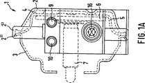
図1Aは、本発明によるダイヤフラム型ブレーキシリンダの部分断面図を示し、
図1Bは、図1Aに対して90度回転し、図1Aに対応している図式図を示し、
図2Aは、本発明による複合型ブレーキシリンダの別の実施例の部分断面図を示し、
図2Bは、図2Aに対して90度回転し、図2Aに対応している図式図を示し、
図3は、一体化されたブレーキシリンダを備えたディスクブレーキの実施例を示し、
図4は、図1のディスクブレーキ用に適当な制御モジュールの斜視図を示し、
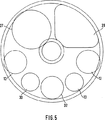
図5は、図4の制御モジュールの上面図を示し、そして
図6は、図3によるブレーキのための図4の制御モジュールを備えたブレーキキャリパの斜視図を示す。
【0017】
図1は商用車の圧縮空気作動型ディスクブレーキ用ダイヤフラム型ブレーキシリンダ1を示しており、これは本質的に2つのハウジング部分(締結部分2′を備えたキャップ2と挿入されたばねリング2″で、これは下側部分3の突起3′囲んでいる。)を有し、これによりハウジング部分の一方、ここではキャップ2、が圧縮空気給排用ベント空間4を囲んでいる。ダイヤフラム型シリンダの流体作動は通常の態様で行われる、即ちブレーキの作動及び解除の際に、ダイヤフラム5はピストン6及びピストンロッド7と共に往復動をする。ベント空間を閉じているシリンダ1のキャップ2に直接制御モジュール8が形成され、これは電子制御部分及び空圧機構の制御部分を有し、これによってブレーキシリンダへ空気圧力が調節自在に導入され、且つ内部が低圧になり得る。この目的のために、制御モジュール8は更に2個の空圧ジョイント(9,10)を有しており、ここにおいてブレーキシリンダ1の空圧ジョイント9は、完全な−従来の設計で構成された−空気戻り、つまり戻り面(図示せず。)に連結され、そして空圧ジョイント10は、制御モジュール8のための圧縮空気供給を行う。
【0018】
制御モジュール8は、ここにおいて1個のリレーバルブ11、種々の機能を実現するための複数の電磁弁12(そのうち一つが図1Bの断面図に示されている。)、圧力センサ13及びディスクブレーキのライニング摩耗センサへの接続部14を有していて、これによりシュー摩耗センサ及び圧力センサ13の情報は、プラグプレート15の母線ラインを経由して(図示されていない)制御装置へ導かれ、一方制御装置から制御モジュールへの制御信号は、対応の多心ケーブル(図示されていない。)を経由して電気プラグ16に供給される。制御モジュール8における空圧要素及び電子要素の詳細な構造及び回路構成はそれぞれの要求形状に依存し、当業者によって更なる手段無しに任意に実施することができる。
【0019】
制御モジュールは中央の支持フレーム部分17を有し、これはキャップ2のハウジングと一体的に形成されると共に制御モジュールの個々の要素が装着されている空所を有し、単純で有利な態様で追加的にプラグプレート15と包囲体18によって外側から囲まれている。
【0020】
図1A及び図1Bに別々に、空圧ジョイント及び電気プラグが互いに峻別されていることが留意される(図1Aにおいて上側に空圧ジョイントが設けられ、図1Bにおいてこれらが下側にある。)。図1に似た制御モジュールの配置がその他の点でピストンシリンダについて実現可能である。
【0021】
図2A及び図2Bが本質的に3つのハウジング部分(キャップ200′、中間部分19、下側部分3′)から組み立てられているピストンシリンダ1′を示しており、ハウジング部分の一つ−ここでは中間部分19−がベント空間4′を囲んでいる。ダイヤフラム型シリンダ部分Aとばね負荷−ピストンシリンダ部分Bとを備えたピストンシリンダの空圧機構機能は、本発明に基づき従来の配置に反せずに変更されねばならない。制御モジュール8は再び、ベント空間を取り囲むハウジング部分、ここでは中間部分19、に直接配置され、ここにおいて制御モジュール8はその機能構成において図1の実施例に対応している。本発明のこの実施形態の主たる利点は再び、中間部分19の軽微な変更のみが必要であり、且つシリンダ1の他の部品が本発明に基づいて変更される必要が無いという点にある。
【0022】
図3は、摩擦板24の方向へのブレーキシュー22、25のクランプのための作動機構21を具備した商用車用圧縮空気作動型ディスクブレーキ20を示している。特に、ブレーキシリンダ1′が一体化しているブレーキキャリパ23(図6も参照)の洗練されたレイアウトが好ましい。好ましくは一体構造のブレーキキャリパ23は、このために本質的に3個の部分領域:ブレーキシリンダ1′の外側ハウジングを形成し且つピストンシリンダの従来の内部部品(ピストンロッド7、プラスチックピストン7′、ばね7″)を内蔵している第1の部分領域23a、これに接して形成され内部にディスクブレーキ20の作動機構21が配置されている第2の部分領域23b、及び第2の部分領域23bに接して形成されると共に摩擦板24と2個のブレーキシュー22、25を取り囲んでおり、ディスクブレーキの作動側(又、作動機構21の側)から受動側へクランプ力を伝えるように機能する第3の部分領域23c:を有している。代替として、ディスクブレーキの重量を更に低減するために、この第3の部分領域23bを、摩擦板24とブレーキシュー22、25を取り囲む、分割バンド又は本体の型に従って形成することも考えれる(図示されない。)。
【0023】
ブレーキキャリパ23内へのブレーキシリンダ1′の一体化により、制御ユニットを受け入れるシリンダ第2室のブレーキ内部空間(領域23b)に対するシールの必要性が低下する。このシールは、ブレーキシリンダ1′及び領域23bの2次室の自動的或いは制御されたベントシステムによって置換され、これは((図示しない弁を介して)圧縮空気システムから流入空気を受け入れ、そして周囲環境へ流出空気を放出する。こうして、ブレーキの内部空間において常に乾燥空気のみが(場合によってはある圧力以下であって)コンプレッサ出口から入り、他のカプセルが必要ないという特に前述した利点が得られる。これは、種々の制御要素が湿度感受性があり、そのようにして湿度から確実に防護されるので、効果において特別なものである。二次室及び領域23b内の圧力は、ゲージ圧で約20−50ミリバールにあるのが推奨される。このようにして、ブレーキ内部空間全体が簡単なやり方で腐食から確実に保護される。
【0024】
更に、制御モジュール8′(破線で外形が示されている。)を図4及び図5のようにブレーキキャリパの第1部分領域23a及び/又は第2部分領域23b並びにブレーキシリンダ1′に連結一体化することは特に有利である。これは、制御モジュール8′が図4のように円形の基盤26(突出縁26′を具備)をプラスチックの支持体として有し、これに制御モジュール8′の個々のセクター状に且つ機能的に配設されて収容されることによって驚く程簡単なやり方で可能となる。
【0025】
図4の実施例において、基盤26の上に例えば電磁弁(例えばABS−ダイヤフラム型弁)27、排気マフラー28、2個の比例弁29a,29b、圧力調整弁30、差圧センサ31、及び摩耗センサ或いはこの機能を持ち旦つ更に調整を可能とする電子伝達調整モータ32が配置される。調整モータ32は、2本スピンドル型ブレーキ(書き入れていない。)の両調整スピンドル間の同期作動に作用し、そして例えば歯車を介して同期チェーン、歯付きベルト又は同期歯車列を駆動する。
【0026】
シリンダ1′のピストンロッドがそこを貫通して延びる穴26″を基盤26の中心領域に備えている、図4及び図5のような個別部品のセクター状配置の特別の利点は、それに取り付けられる部品を含む基盤26が個別部品の一部…特に相対的に長く延びている比例電磁弁29a、29b…が、第1の部分領域23aから第2の部分領域23bへ突入するように、ブレーキキャリパ23の第1の部分領域23a(つまりブレーキシリンダハウジング)の中に取り付けられ、そしてこれにより、普通の技術レベルでは使用されていない空間が使用されることが予測できないやり方で可能になっている点にある。その上に、制御モジュールは、ブレーキの寸法が増大すること無しに、ブレーキ機構の内部に完全に収容され且つ機械的に保護される。その上に、電子調整モータに接続しているブレーキキャリパ23とブレーキシリンダ1′の付加的な一体化により、そうでなければ必要な、純粋に機械的な調整装置が省略され、空間の必要性は更に低下する。第2の部分領域23bの中央セクションは、シリンダのピストンロッド6の動き用及び偏心クランプを作動するための回転レバーの動き用空間として在来のやり方で使用できる。図4の実施例において、回転レバーは確かに、レバー端33′の回転軸に偏心して取り付けられた偏心軸35の上方にでなく、2スピンドル型ブレーキのクランプトラバース36に直接作用し、ここにおいて偏心軸35は、ブレーキキャリパ23に対して支持ために機能する。ハンガー37は、作動機構21を一緒に支持し、事前に取り付けられたユニットとしてのブレーキキャリパ領域23bへの作動機構21の挿入を可能にする。
【0027】
要約するに、図1及び図2の変形例によってEBS機能を備えた現存のディスクブレーキシステムの複雑でない部品供給の可能性が生ずる。図3によれば、それ以上に標準化可能でコスト的に有利なディスクブレーキが得られ、これは外形的にコンパクトであり、制御モジュールも事前に取り付けられているユニットとしての作動機構も迅速に且つ複雑でなく一体化される。
【図面の簡単な説明】
【図1A】図1Aは、本発明によるダイヤフラム型ブレーキシリンダの部分断面図を示す。
【図1B】図1Bは、図1Aに対して90度回転し、図1Aに対応している図式図を示す。
【図2A】図2Aは、本発明による複合型ブレーキシリンダの別の実施例の部分断面図を示す。
【図2B】図2Bは、図2Aに対して90度回転し、図2Aに対応している図式図を示す。
【図3】図3は、一体化されたブレーキシリンダを備えたディスクブレーキの実施例を示す。
【図4】図4は、図1のディスクブレーキ用に適当な制御モジュールの斜視図を示す。
【図5】図5は、図4の制御モジュールの上面図を示す。
【図6】図6は、図3によるブレーキのための図4の制御モジュールを備えたブレーキキャリパの斜視図を示す。
【符号の説明】
1 ダイヤフラム型ブレーキシリンダ
2 キャップ
3 下側部分
4 ベント空間
5 ダイヤフラム
6 ピストン
7 ピストンロッド
7′ ピストン
7″ ばね
8 制御モジュール
9,10 空圧ジョイント
11 リレーバルブ
12 電磁弁
13 圧力センサ
14 接続部
15 プラグプレート
16 プラグ
17 支持フレーム部分
18 包囲体
19 中間部分
A ダイヤフラム型シリンダ部分
B ばね付き−ピストンシリンダ部分
20 ディスクブレーキ
21 作動機構
22,25 ブレーキシュー
23 ブレーキキャリパ
24 摩擦板
26 基盤
27 ABS−ダイヤフラム弁
28 排気マフラー
29a,b 比例弁
30 圧力調整弁
31 差圧センサ
32 伝達調整モータ
33 回転レバー
34 偏心クランプ
35 偏心軸
36 クランプトラバース
37 圧縮空気配管[0001]
The invention relates to a compressed air actuated disc brake according to the premise of claim 1.
[0002]
A conventional disc brake is known from DE 40 32 885 A1. The commercial vehicle disc brakes shown in this publication inherently show that it is desirable to be uneven and structurally simple to reduce manufacturing costs. The same is important for the braking devices disclosed in
[0003]
Various types of compressed air cylinder, for example, "Bosch Automotive Technology Handbook" 22 Edition, known by ISBN3-19-419122-2. This publication lists on page 655 a reliable standard example of a cylinder that is both a piston structure and a diaphragm structure, and a combined single-chambered cylinder with a spring.
[0004]
The aforementioned cylinders are likewise proven themselves and are reliable components of the entire brake system as a whole. The present invention, in the starting point, disc brakes, considering the detail speaking all braking systems, the individual components, in particular the cylinder, state-of-the-art electronic control brake system in harmony (EBS brake system) and optimization It is with the idea to say that.
[0005]
The invention achieves these objects by means of claim 1. Disk brake according to the present invention, as compared to the normal disk brakes, in the brake, and / or in the brake cylinders belonging to it, at least one control module electronic components and the flow body Organization components (especially full And EBS wheel module). The present invention further achieves that objective, in which a control module is arranged directly in one of the housing parts of the brake cylinder in a conventional brake cylinder.
[0006]
The present invention realizes an advantageous and cost-effective integration of the control module with its own disc brake, in particular its brake cylinder, and so far a separate component (disc brake with control module). Brake cylinders and other parts) into a single structural unit.
[0007]
Under the implementation of all the electronic control elements and machine 械制 integrating control element to the wheel brake (arranged to) that latest electronic braking system, a need for a vehicle brake, which is knowledge of the recent increase ing. In particular, this will greatly reduce the installation costs in the vehicle.
[0008]
Here, the sprouted idea of wheel-related control module that usefully coupled together the electronic components and the flow body part products. For example, such a module is guided compressed air conduit and electronic control cables in the module, the flow body parts and electronic components of the control module, "to adjust the pressure in the brake cylinder" and "pressure It is arranged so that at least the function of “decrease” can be realized. For this purpose, the control module comprises, for example, a relay valve, preferably several solenoid valves in communication with the relay valve, a pressure sensor, a bus line, a compressed air line and the like. Preferably, the control modules of the different wheels are able to communicate with each other, either via a control device or directly.
[0009]
Now, if the control module is combined with the disc brake and / or brake cylinder as a single component in accordance with the present invention, the installation and piping costs are reduced, because several separate elements are now one. This is because it is only a component and is integrated and incorporated in the installation space of the wheel brake.
[0010]
A particularly preferred variant of the invention is characterized in that the brake cylinder and the disc brake form one structural unit. This variation of the present invention greatly simplifies the structure of the disc brake (i.e., in some cases also when the control module is not integrated in the disc brake). Integration of the control module, first, to cod also deletion of additional housing and The required electronic coupling conductor and the flow body binding conductor otherwise. The additional integration of the brake cylinder into the brake structure is still a necessary connection between the brake cylinder and disc brake components, which always causes additional mistakes in repair and installation. If you also, but to eliminate the.
[0011]
According to a particularly preferred and practical variant of the invention, the brake cylinder is further integrated in the brake caliper . This ensures that no debris enters the brake caliper when the brake cylinder is replaced. In order to replace the brake cylinder, it is only necessary to replace the insert with the brake cylinder internal parts (piston, piston rod, etc.). There is no need for an additional seal and there is a possibility that the entire interior space of the brake is always exposed only to dry compressed air from the brake system, which also reduces the risk of corrosion. This will become clear from the description of the drawings.
[0012]
The present invention further achieves the possibility of a standardized brake cylinder that no longer needs to be adapted for different insertion purposes. This is particularly valuable when the control module is arranged to be implemented with full EBS functionality. In particular, in this connection, it is also advantageous when adjustments are made with an electrically adjustable motor of a brake that is otherwise fluidly operated. The adjustment mechanism can be made particularly cheap by means of an electric adjustment motor and suitable software. The construction of the cylinder as a piston cylinder further gives rise to the possibility of a particularly compact structure.
[0013]
According to another particularly preferred embodiment of the invention, the control module is mounted directly on the housing part for the vent space. The control module is advantageously and simply arranged in one part of the brake, where it only has to be changed essentially, to incorporate the control module in it. This variant of the invention also has the particular advantage that the control module is attached to the brake cylinder parts directly and without the need for a separate inner or outer supply pipe, but it is in the vent space of the cylinder. Has direct access. This allows the piston working air to be introduced immediately after the piston. As a result, when other components such as the control module are mounted on the housing, the remaining components such as the cap, the piston, and the diaphragm are provided with the control module in the brake cylinder as compared with the conventional structure. There is a further advantage that no further changes are required. An advantage of this variant of the invention is that a flange connection to the brake, preferably a flange connection to a compressed air actuated disc brake for trucks, does not need to be applied because of the integral module. . Another essential advantage of the present invention is found to be that it is generally not complex and that it is possible to install an EBS brake system in a vehicle series having a conventional brake system without the need for other components. . The modification of the control module is performed at no additional cost if the housing is adapted in a simple manner. Finally, the advantage to be mentioned is that the cap of the prior art compressed air cylinder is the most easily changed part of a commercial vehicle brake.
[0014]
Other advantageous embodiments of the invention can be seen from the subclaims.
[0015]
The invention will now be described in detail with reference to the drawings.
[0016]
FIG. 1A shows a partial cross-sectional view of a diaphragm type brake cylinder according to the present invention,
1B shows a schematic diagram corresponding to FIG. 1A, rotated 90 degrees relative to FIG.
FIG. 2A shows a partial sectional view of another embodiment of a composite brake cylinder according to the invention,
2B shows a schematic diagram corresponding to FIG. 2A, rotated 90 degrees relative to FIG.
FIG. 3 shows an embodiment of a disc brake with an integrated brake cylinder,
4 shows a perspective view of a control module suitable for the disc brake of FIG.
5 shows a top view of the control module of FIG. 4 and FIG. 6 shows a perspective view of a brake caliper with the control module of FIG. 4 for the brake according to FIG.
[0017]
FIG. 1 shows a diaphragm brake cylinder 1 for a compressed air actuated disc brake of a commercial vehicle, which essentially consists of two housing parts (a cap 2 with a fastening part 2 'and an inserted spring ring 2 ". , Which surrounds the projection 3 'of the lower part 3), whereby one of the housing parts, here the cap 2, surrounds the compressed air supply / exhaust vent space 4. The diaphragm cylinder Fluid actuation takes place in the normal manner, i.e., when the brake is actuated and released, the
[0018]
The
[0019]
The control module has a central
[0020]
Separately in FIGS. 1A and 1B, it pneumatic joint provided on the upper side (FIG. 1A is noted that the pneumatic joint and electrostatic Kipu lugs are distinguished from each other, it is in the lower side in FIG. 1B .) A control module arrangement similar to that of FIG. 1 is otherwise possible for the piston cylinder.
[0021]
2A and 2B show a piston cylinder 1 'assembled from essentially three housing parts (cap 200',
[0022]
FIG. 3 shows a compressed air actuated
[0023]
The integration of the brake cylinder 1 'in the
[0024]
Further, the control module 8 '(the outline is indicated by a broken line) is integrally connected to the first
[0025]
In the embodiment of FIG. 4, for example, an electromagnetic valve (for example, ABS-diaphragm type valve) 27, an
[0026]
The special advantage of the sectoral arrangement of individual parts, such as in FIGS. 4 and 5, where the piston rod of the cylinder 1 ′ is provided with a
[0027]
In summary, the variant of FIGS. 1 and 2 gives rise to the possibility of an uncomplicated component supply of an existing disc brake system with EBS function. According to FIG. 3, an even more standardized and cost-effective disc brake is obtained, which is compact in shape, has a control module as well as a pre-installed operating mechanism quickly and It is not complicated and integrated.
[Brief description of the drawings]
FIG. 1A shows a partial cross-sectional view of a diaphragm type brake cylinder according to the present invention.
FIG. 1B shows a schematic diagram corresponding to FIG. 1A, rotated 90 degrees with respect to FIG. 1A.
FIG. 2A shows a partial cross-sectional view of another embodiment of a composite brake cylinder according to the present invention.
2B shows a schematic diagram corresponding to FIG. 2A, rotated 90 degrees relative to FIG. 2A.
FIG. 3 shows an embodiment of a disc brake with an integrated brake cylinder.
FIG. 4 shows a perspective view of a control module suitable for the disc brake of FIG.
FIG. 5 shows a top view of the control module of FIG. 4;
6 shows a perspective view of a brake caliper with the control module of FIG. 4 for the brake according to FIG. 3;
[Explanation of symbols]
DESCRIPTION OF SYMBOLS 1 Diaphragm type brake cylinder 2
Claims (13)
a)摩擦板(24)の方向へブレーキシュー(22,25)をクランプするための作動機構(21)と、
b)圧縮空気の作用により該作動機構を介してブレーキ作用を始めるブレーキシリンダ(1、1′)とを備えている形式のものにおいて、
c)該ディスクブレーキ及び該ブレーキシリンダ(1、1′)、又は該ディスクブレーキもしくは該ブレーキシリンダ(1、1′)の中にそれぞれ単一電子部品及び空圧機構を有する単一部品を備えた、ブレーキシリンダ内の空気圧力を調節するための少なくとも一つの制御モジュールが一体化されており、
d)該制御モジュールが更に電動調整モータを有しており、
e)該ブレーキシリンダ(1′)とディスクブレーキとが構造的なユニットを形成している
ことを特徴とする車両用圧縮空気作動型ディスクブレーキ。A compressed air actuated disc brake (20),
a) an actuating mechanism (21) for clamping the brake shoes (22, 25) in the direction of the friction plate (24);
b) in a type comprising a brake cylinder (1, 1 ') which starts a braking action via the operating mechanism by the action of compressed air;
c) the disc brake and the brake cylinder (1, 1 ') or the disc brake or the brake cylinder (1, 1') with a single electronic component and a single component having a pneumatic mechanism, respectively. Integrated with at least one control module for adjusting the air pressure in the brake cylinder,
d) the control module further comprises an electric adjustment motor;
e) A compressed air-operated disc brake for vehicles, wherein the brake cylinder (1 ') and the disc brake form a structural unit.
該ブレーキシリンダ(1′)の外側ハウジングを形成している第1の部分領域(23a)、
それに接触して形成され、内部に該作動機構(21)が配置されている第2の部分領域(23b)、及び
該第2の部分領域(23b)に接触して形成され、摩擦板(24)と2つのブレーキシュー(22,25)を取り囲み、作動側から受動側へクランプ力を伝達するように機能する第3の部分領域(23c)、
を有することを特徴とする前記請求項2記載の車両用圧縮空気作動型ディスクブレーキ。A first partial area (23a) in which the brake caliper (23) essentially forms three partial areas, namely the outer housing of the brake cylinder (1 ');
The friction plate (24) is formed in contact with the second partial region (23b) in which the actuating mechanism (21) is disposed, and in contact with the second partial region (23b). ) And two brake shoes (22, 25) and a third partial region (23c) which functions to transmit the clamping force from the operating side to the passive side,
The compressed air actuated disc brake for a vehicle according to claim 2, characterized by comprising:
Applications Claiming Priority (3)
| Application Number | Priority Date | Filing Date | Title |
|---|---|---|---|
| DE19652806 | 1996-12-18 | ||
| DE19652806.2 | 1996-12-18 | ||
| PCT/EP1997/007099 WO1998026968A1 (en) | 1996-12-18 | 1997-12-18 | Brake cylinder for compressed-air brakes |
Publications (3)
| Publication Number | Publication Date |
|---|---|
| JP2001506352A JP2001506352A (en) | 2001-05-15 |
| JP2001506352A5 JP2001506352A5 (en) | 2008-05-01 |
| JP4145960B2 true JP4145960B2 (en) | 2008-09-03 |
Family
ID=7815225
Family Applications (1)
| Application Number | Title | Priority Date | Filing Date |
|---|---|---|---|
| JP52732998A Expired - Fee Related JP4145960B2 (en) | 1996-12-18 | 1997-12-18 | Compressed air actuated disc brake for vehicles |
Country Status (6)
| Country | Link |
|---|---|
| US (1) | US6234587B1 (en) |
| EP (1) | EP0944511B1 (en) |
| JP (1) | JP4145960B2 (en) |
| BR (1) | BR9714405A (en) |
| DE (2) | DE59712372D1 (en) |
| WO (1) | WO1998026968A1 (en) |
Families Citing this family (34)
| Publication number | Priority date | Publication date | Assignee | Title |
|---|---|---|---|---|
| DE59712372D1 (en) * | 1996-12-18 | 2005-08-25 | Knorr Bremse Systeme | Air-operated disc brake |
| DE19953805C1 (en) * | 1999-11-09 | 2001-06-21 | Daimler Chrysler Ag | Combined service and spring brake cylinder and brake device for commercial vehicles |
| DE10021571B4 (en) * | 2000-05-03 | 2010-04-29 | Knorr-Bremse Systeme für Nutzfahrzeuge GmbH | Air-operated disc brake with pressure elements |
| WO2002014711A2 (en) | 2000-08-17 | 2002-02-21 | Knorr-Bremse Systeme für Nutzfahrzeuge GmbH | Disc brake comprising a synchronised adjusting system |
| DE10109305A1 (en) * | 2001-02-26 | 2002-09-05 | Daimler Chrysler Ag | Electromechanical vehicle brake |
| DE10148480A1 (en) | 2001-10-01 | 2003-04-17 | Knorr Bremse Systeme | Parking brake device and method for actuating the parking brake |
| DE10150047A1 (en) * | 2001-10-10 | 2003-06-26 | Knorr Bremse Systeme | Control method for disc brakes |
| DE10152248B4 (en) * | 2001-10-23 | 2006-03-16 | Knorr-Bremse Systeme für Nutzfahrzeuge GmbH | Disc brake with electric motor operated adjustment system |
| DE10156503B4 (en) | 2001-11-16 | 2006-06-14 | Knorr-Bremse Systeme für Nutzfahrzeuge GmbH | Control method for controlling a readjustment system of a disc brake and control device |
| DE10252301B4 (en) * | 2002-02-13 | 2006-01-05 | Knorr-Bremse Systeme für Nutzfahrzeuge GmbH | Disc brake with electrically driven adjusting device |
| DE50301230D1 (en) | 2002-02-13 | 2005-10-27 | Knorr Bremse Systeme | DISC BRAKE WITH ELECTRIC MOTORIZED ADJUSTING DEVICE AND METHOD FOR CONTROLLING A DISC BRAKE |
| JP2005521835A (en) | 2002-02-13 | 2005-07-21 | クノル−ブレムゼ ジステーメ フューア ヌッツファールツォイゲ ゲゼルシャフト ミット ベシュレンクテル ハフツング | Disc brake with electric drive type adjustment device |
| US7720910B2 (en) * | 2002-07-26 | 2010-05-18 | International Business Machines Corporation | Interactive filtering electronic messages received from a publication/subscription service |
| US9124447B2 (en) * | 2002-07-26 | 2015-09-01 | International Business Machines Corporation | Interactive client computer communication |
| EP1546571B1 (en) * | 2002-09-23 | 2006-04-12 | KNORR-BREMSE SYSTEME FÜR NUTZFAHRZEUGE GmbH | Pneumatically actuated disk brake comprising an adjustment device |
| US6755233B2 (en) * | 2002-11-05 | 2004-06-29 | Haldex Brake Corporation | Method and apparatus for positioning an end of a push rod of a brake actuator |
| DE10320607B3 (en) | 2003-05-08 | 2004-07-01 | Knorr-Bremse Systeme für Nutzfahrzeuge GmbH | Integrated electronic control system for disk brake of utility vehicle has housing for control circuit mounted on brake saddle connected to brake application cylinder and tire air pressure sensor |
| GB0312459D0 (en) * | 2003-05-30 | 2003-07-09 | Meritor Heavy Vehicle Braking | Air brake assembly |
| RU2003124598A (en) * | 2003-08-07 | 2005-02-10 | Александр Николаевич Марти (RU) | PNEUMATIC DISK BRAKE |
| US20050110342A1 (en) * | 2003-11-24 | 2005-05-26 | Eberling Charles E. | Brake actuator with integral antilock modulator |
| DE10359040B4 (en) * | 2003-12-17 | 2006-03-23 | Knorr-Bremse Systeme für Nutzfahrzeuge GmbH | Electronically controlled braking system |
| DE102004045952B3 (en) * | 2004-09-22 | 2006-01-19 | Knorr-Bremse Systeme für Nutzfahrzeuge GmbH | Disc brake with electric motor operated adjustment system |
| US7493993B2 (en) * | 2005-08-26 | 2009-02-24 | Haldex Brake Products Ab | Brake system having a reduced length and an axially mounted actuator |
| US20080047787A1 (en) * | 2006-08-23 | 2008-02-28 | Bendix Spicer Foundation Brake, Llc | Disc brake actuator mounting arrangement |
| GB2457224B (en) | 2007-12-24 | 2012-03-28 | Meritor Heavy Vehicle Braking | Brake actuator |
| DE102009031559A1 (en) * | 2008-07-04 | 2010-01-07 | Knorr-Bremse Systeme für Nutzfahrzeuge GmbH | Pneumatically actuated disc brake and brake cylinder |
| DE102008051118A1 (en) | 2008-10-09 | 2010-06-17 | Knorr-Bremse Systeme für Nutzfahrzeuge GmbH | Vehicle brake cylinder with tilting of a stiff brake piston tolerant seal assembly |
| JP5366753B2 (en) * | 2009-10-09 | 2013-12-11 | 日野自動車株式会社 | Disc brake device |
| WO2015040652A1 (en) * | 2013-09-19 | 2015-03-26 | 株式会社Tbk | Disc brake device |
| EP2995834B1 (en) * | 2014-09-15 | 2020-02-26 | Meritor Heavy Vehicle Braking Systems (UK) Limited | A brake assembly and a method of assembling said brake assembly |
| FR3031249B1 (en) * | 2014-12-31 | 2018-05-25 | Foundation Brakes France | ELECTRIC MOTORIZATION DEVICE FOR BRAKE ACTUATOR, METHOD FOR COMMUNICATING SUCH A MOTORIZATION DEVICE, AND METHOD FOR INDUSTRIALIZING SUCH A MOTORIZATION DEVICE |
| DE102016117593A1 (en) | 2016-09-19 | 2018-03-22 | Knorr-Bremse Systeme für Nutzfahrzeuge GmbH | Pneumatic disc brake |
| CN112682440A (en) * | 2019-10-17 | 2021-04-20 | 威伯科印度有限公司 | Spring brake actuator comprising an integrated valve unit |
| DE102022117597A1 (en) | 2022-07-14 | 2024-01-25 | Miro Gudzulic | Brake system for at least one vehicle axle of a truck |
Family Cites Families (21)
| Publication number | Priority date | Publication date | Assignee | Title |
|---|---|---|---|---|
| FR1506522A (en) | 1966-11-08 | 1967-12-22 | Saviem | Advanced spring brake |
| DE1655854A1 (en) | 1967-11-30 | 1971-08-12 | Westinghouse Bremsen Und Appba | Safety device for spring brake cylinder |
| US3768875A (en) * | 1970-09-25 | 1973-10-30 | Bendix Corp | Adaptive control for fluid pressure braking system |
| DE2101573A1 (en) * | 1971-01-14 | 1972-07-27 | Graubremse Gmbh, 6900 Heidelberg | Air cylinder |
| US3799297A (en) * | 1971-01-21 | 1974-03-26 | Honeywell Inc | Pneumatic brake system |
| GB1319202A (en) * | 1971-03-27 | 1973-06-06 | Fiat Spa | Tractor and trailer combination |
| AT331660B (en) * | 1971-09-17 | 1976-08-25 | Graubremse Gmbh | DEVICE FOR QUICKLY REGULATING THE PRESSURE IN THE INDIVIDUAL PNEUMATIC BRAKE CYLINDER OF VEHICLE BRAKING SYSTEMS WITH ANTI-SKID CONTROL |
| GB1359487A (en) | 1971-09-24 | 1974-07-10 | Mullard Ltd | Brake antilock mechanism |
| US3980348A (en) * | 1971-11-13 | 1976-09-14 | Girling Limited | Fluid flow control valves |
| DE2524427A1 (en) * | 1975-06-03 | 1976-12-09 | Wabco Westinghouse Gmbh | ANTI-SKID CONTROL SYSTEM |
| DE2541563A1 (en) * | 1975-09-18 | 1977-03-24 | Bosch Gmbh Robert | Anti blocking dual circuit air brake - with large diameter venting duct by having modulating valve directly on brake cylinder |
| US4014579A (en) * | 1975-12-17 | 1977-03-29 | Wabco Westinghouse Gmbh | Spring actuated brake cylinder with release piston lockout means |
| DE2627284C2 (en) * | 1976-06-18 | 1982-11-11 | Wabco Fahrzeugbremsen Gmbh, 3000 Hannover | Anti-lock control system for pressure medium-operated vehicle brakes, in particular for road vehicles |
| DE3236535A1 (en) * | 1982-10-02 | 1984-04-05 | Robert Bosch Gmbh, 7000 Stuttgart | CONTROL OR REGULATION SYSTEM |
| DE4032885A1 (en) | 1990-10-17 | 1992-04-23 | Knorr Bremse Ag | DISC BRAKE FOR VEHICLES, IN PARTICULAR ROAD VEHICLES |
| DE4100966A1 (en) | 1991-01-15 | 1992-07-16 | Teves Gmbh Alfred | WHEEL BRAKE ASSEMBLY FOR MODULAR BRAKE SYSTEM |
| US5118165A (en) * | 1991-01-29 | 1992-06-02 | Allied-Signal Inc. | Electro-pneumatic spring and service brake actuator |
| DE4314720A1 (en) * | 1993-05-04 | 1994-11-10 | Knorr Bremse Ag | Air operated disc brake |
| DE19515063C2 (en) * | 1995-04-27 | 2002-06-06 | Knorr Bremse Systeme | Disc brake for vehicles, in particular road vehicles |
| DE19518513C2 (en) * | 1995-05-19 | 2002-09-26 | Knorr Bremse Systeme | Bremszuspannvorrichtung |
| DE59712372D1 (en) * | 1996-12-18 | 2005-08-25 | Knorr Bremse Systeme | Air-operated disc brake |
-
1997
- 1997-12-18 DE DE59712372T patent/DE59712372D1/en not_active Expired - Lifetime
- 1997-12-18 DE DE19756519A patent/DE19756519A1/en not_active Ceased
- 1997-12-18 WO PCT/EP1997/007099 patent/WO1998026968A1/en active IP Right Grant
- 1997-12-18 JP JP52732998A patent/JP4145960B2/en not_active Expired - Fee Related
- 1997-12-18 EP EP97954923A patent/EP0944511B1/en not_active Expired - Lifetime
- 1997-12-18 US US09/330,013 patent/US6234587B1/en not_active Expired - Lifetime
- 1997-12-18 BR BR9714405-3A patent/BR9714405A/en not_active IP Right Cessation
Also Published As
| Publication number | Publication date |
|---|---|
| WO1998026968A1 (en) | 1998-06-25 |
| DE59712372D1 (en) | 2005-08-25 |
| JP2001506352A (en) | 2001-05-15 |
| BR9714405A (en) | 2000-04-18 |
| EP0944511A1 (en) | 1999-09-29 |
| DE19756519A1 (en) | 1998-10-15 |
| US6234587B1 (en) | 2001-05-22 |
| EP0944511B1 (en) | 2005-07-20 |
Similar Documents
| Publication | Publication Date | Title |
|---|---|---|
| JP4145960B2 (en) | Compressed air actuated disc brake for vehicles | |
| JP2001506352A5 (en) | ||
| USRE38874E1 (en) | Disc brake for vehicles having insertable actuator | |
| CA1323847C (en) | Stroke indicator for air operated diaphragm spring brakes | |
| CA2099388A1 (en) | Brake monitoring system | |
| RU2506180C2 (en) | Air-driven disc brake mechanism and brake cylinder | |
| EP1167147A3 (en) | Vehicle braking system using stored vehicle parameters for electronic control of braking | |
| WO2013048631A1 (en) | Parking brake chamber internal breathing system | |
| US6068091A (en) | Externally mounted bracket system for disc brakes | |
| RU2041091C1 (en) | Device to control electrically controlled brake circuit of multicircuit brake system | |
| US10626939B2 (en) | Adhesive attachment of the disc brake pushrod plate to the diaphragm | |
| US6549126B2 (en) | Dry interface corner actuator single sensor for lining wear and low reservoir detection | |
| US10663025B2 (en) | Bushing assembly for a spring brake actuator of a vehicle air braking system | |
| US5031404A (en) | Pressurized air booster | |
| JPH09508336A (en) | Pressure regulator for hydraulic brake system with slip control | |
| US5099965A (en) | Rail braking actuation device | |
| US4884403A (en) | Modular brake actuator | |
| US5957032A (en) | Air-operated brake actuator mounting | |
| US3747705A (en) | Compact adaptive braking system | |
| US2084416A (en) | Brake | |
| KR100444459B1 (en) | disk brake of vehicles | |
| WO2008094122A1 (en) | Brake device for synchronizing of gears in a gear box and gear box provided therewith | |
| CA2339343A1 (en) | Intelligent disk brake assembly | |
| KR100217675B1 (en) | Wheel cylinder having adjusting device for brake shoe clearance | |
| KR100257012B1 (en) | Brake cam driving device of air brake system |
Legal Events
| Date | Code | Title | Description |
|---|---|---|---|
| A621 | Written request for application examination |
Free format text: JAPANESE INTERMEDIATE CODE: A621 Effective date: 20040929 |
|
| A131 | Notification of reasons for refusal |
Free format text: JAPANESE INTERMEDIATE CODE: A131 Effective date: 20070327 |
|
| A601 | Written request for extension of time |
Free format text: JAPANESE INTERMEDIATE CODE: A601 Effective date: 20070625 |
|
| A602 | Written permission of extension of time |
Free format text: JAPANESE INTERMEDIATE CODE: A602 Effective date: 20070813 |
|
| A521 | Written amendment |
Free format text: JAPANESE INTERMEDIATE CODE: A523 Effective date: 20070725 |
|
| A02 | Decision of refusal |
Free format text: JAPANESE INTERMEDIATE CODE: A02 Effective date: 20071106 |
|
| A524 | Written submission of copy of amendment under section 19 (pct) |
Free format text: JAPANESE INTERMEDIATE CODE: A524 Effective date: 20080226 |
|
| A72 | Notification of change in name of applicant |
Free format text: JAPANESE INTERMEDIATE CODE: A721 Effective date: 20080201 |
|
| A911 | Transfer to examiner for re-examination before appeal (zenchi) |
Free format text: JAPANESE INTERMEDIATE CODE: A911 Effective date: 20080321 |
|
| TRDD | Decision of grant or rejection written | ||
| A01 | Written decision to grant a patent or to grant a registration (utility model) |
Free format text: JAPANESE INTERMEDIATE CODE: A01 Effective date: 20080521 |
|
| A01 | Written decision to grant a patent or to grant a registration (utility model) |
Free format text: JAPANESE INTERMEDIATE CODE: A01 |
|
| A61 | First payment of annual fees (during grant procedure) |
Free format text: JAPANESE INTERMEDIATE CODE: A61 Effective date: 20080619 |
|
| R150 | Certificate of patent or registration of utility model |
Free format text: JAPANESE INTERMEDIATE CODE: R150 |
|
| FPAY | Renewal fee payment (event date is renewal date of database) |
Free format text: PAYMENT UNTIL: 20110627 Year of fee payment: 3 |
|
| FPAY | Renewal fee payment (event date is renewal date of database) |
Free format text: PAYMENT UNTIL: 20120627 Year of fee payment: 4 |
|
| FPAY | Renewal fee payment (event date is renewal date of database) |
Free format text: PAYMENT UNTIL: 20130627 Year of fee payment: 5 |
|
| R250 | Receipt of annual fees |
Free format text: JAPANESE INTERMEDIATE CODE: R250 |
|
| R250 | Receipt of annual fees |
Free format text: JAPANESE INTERMEDIATE CODE: R250 |
|
| R250 | Receipt of annual fees |
Free format text: JAPANESE INTERMEDIATE CODE: R250 |
|
| LAPS | Cancellation because of no payment of annual fees |