JP4145035B2 - Scale with weighing compartment - Google Patents
Scale with weighing compartment Download PDFInfo
- Publication number
- JP4145035B2 JP4145035B2 JP2001299473A JP2001299473A JP4145035B2 JP 4145035 B2 JP4145035 B2 JP 4145035B2 JP 2001299473 A JP2001299473 A JP 2001299473A JP 2001299473 A JP2001299473 A JP 2001299473A JP 4145035 B2 JP4145035 B2 JP 4145035B2
- Authority
- JP
- Japan
- Prior art keywords
- panel
- scale
- panels
- guide
- side wall
- Prior art date
- Legal status (The legal status is an assumption and is not a legal conclusion. Google has not performed a legal analysis and makes no representation as to the accuracy of the status listed.)
- Expired - Fee Related
Links
Images


Classifications
-
- G—PHYSICS
- G01—MEASURING; TESTING
- G01G—WEIGHING
- G01G21/00—Details of weighing apparatus
- G01G21/28—Frames, Housings
- G01G21/286—Frames, Housings with windshields
Landscapes
- General Physics & Mathematics (AREA)
- Physics & Mathematics (AREA)
- Operating, Guiding And Securing Of Roll- Type Closing Members (AREA)
- Power-Operated Mechanisms For Wings (AREA)
- Measurement Of Force In General (AREA)
- Refuse Collection And Transfer (AREA)
- Closures For Containers (AREA)
- Handcart (AREA)
- Golf Clubs (AREA)
- Weight Measurement For Supplying Or Discharging Of Specified Amounts Of Material (AREA)
- Ventilation (AREA)
- Fertilizing (AREA)
- Catching Or Destruction (AREA)
- Feeding And Watering For Cattle Raising And Animal Husbandry (AREA)
- Main Body Construction Of Washing Machines And Laundry Dryers (AREA)
- Sampling And Sample Adjustment (AREA)
- Casings For Electric Apparatus (AREA)
- Conveying And Assembling Of Building Elements In Situ (AREA)
- Physical Deposition Of Substances That Are Components Of Semiconductor Devices (AREA)
- Transmission Devices (AREA)
- Detail Structures Of Washing Machines And Dryers (AREA)
- Transition And Organic Metals Composition Catalysts For Addition Polymerization (AREA)
- Float Valves (AREA)
Abstract
Description
【0001】
【発明の背景】
本発明は、秤の固定部に接する計量区画を備え、計量区画が少なくとも一つの側壁と、前壁と、上部カバーパネルで囲まれ、計量区画を開閉するため少なくとも一つの壁および/または上部カバーパネルが案内装置でスライド自在に動く秤に関する。
【0002】
この種の公知の秤は、たとえばヨーロッパ特許出願EP−A−0 234 008に記載の実施例のように、計量皿と、この計量皿をすべての方向から囲む計量区画を備え、固定の前面ガラスと、後方へスライドする側壁と、後方へスライドする上部カバーパネルと、側壁を上部カバーパネルに接続するコネクタを有している。このコネクタは、側壁および/または上部カバーパネルの開閉時に、側壁および/または上部カバーパネルとともに動き、計量区画へのアクセスが側面のフレーム部材に邪魔されずに自由に行えるように構成されている。さらに、側壁は別々にまたは一緒に開閉し、同時に上部カバーパネルと一緒にまたは別々に動くようになっている。駆動はモータか手動で行う。手動で行う場合、動かそうとする壁はモータ駆動機構から分離される。
【0003】
ヨーロッパ特許出願EP−A−0 574 668は、手動ロック装置で着脱可能な上部カバーパネルを有するドラフト保護ハウジングを備えた秤を開示している。上部カバーパネルが外された後、前壁と側壁をハウジングから完全に取り外して清掃できる。秤のこの公知の構造において、上部カバーパネルは、ドラフト保護ハウジングを一緒に保持するフレームの一部を成す。ある程度まではフレーム部材は壁の邪魔にならないので、オペレータは秤の内部をよく見られるが、用途によっては、この設計でも十分でない。欠点の一つはフレームの上部が必要な要素であることであり、また、ロック要素は、高精度に組み立てなければならないが、受け側の凹部と一直線上に並べるために巧妙な取扱いを要するからである。
【0004】
従来技術の秤では、フレキシブルで変更可能な構成において、導管やホースなどの結合手段を計量区画に導入しなければならない場合、計量工程の間、スライド可能な側壁か上部カバーパネルを少なくとも一部分開けたままにしておく必要があった。なぜなら、剛性のあるフレームや複雑な案内装置を用いると、個別に簡単にアクセス可能な導管を壁に設けることができないからである。しかし、壁を開けたままにしておくと計量結果に誤差が生じることがある。
【0005】
基本的に、公知の秤は、計量区画へ自由にアクセスすることと計量皿への視界を遮らないことを同時には行えないという欠点を有する。側方からと上方からのアクセスを同時に行うことはできず、特に導管やホースなどの接続部へのアクセス性に問題がある。さらに、計量区画は清掃が難しい。
【0006】
【発明の目的】
したがって、本発明の目的は、計量皿が邪魔されずに見えるようにすると同時に、いかなる状況でも常に良好なアクセス性を有する秤を提供することにある。また、この目的は、ユーザの操作を容易にする単純な思想により達成される。計量区画は壁が開放された状態で、計量皿に試料を置くためにアクセスが容易で、また、壁が完全に閉まった状態でも導管やケーブルが通るようにしなければならない。また、複雑な操作なしで簡単に清掃できなければならない。
【0007】
【発明の要約】
本発明は、秤の固定部に部分的に接しているか、あるいは、少なくとも一つの側壁と、前面パネルと、上面カバーパネルに囲まれた計量区画を備え、上記計量区画を開閉するために上記壁および/または上面カバーパネルの一つを案内装置によってスライド自在にした秤について、上記の問題を解決する方法を提案する。本発明によれば、上記少なくとも一つのスライド自在の壁パネルを保持する機構は上記案内装置と一体に設けられ、固定された壁パネルの各々を保持する機構は秤の固定部と一体に設けられている。壁パネルはそれぞれ、対応するホルダーで所定の位置に取り外し可能に保持されており、このホルダーは、上記壁パネルおよび/または上記保持機構に力を加えるだけで作動する形状ロック閉鎖装置を係合、解放することによりロック、アンロックが可能である。
【0008】
側壁と前壁と上面カバーパネルは、手で動かして外向きにわずかに傾ければ秤から分離可能であり、たとえば、通常ガラス製である壁プレートの清掃が簡単になる。側壁と前壁と上面カバーパネルは、作動位置にある場合には、所定の位置にしっかりロックされている。これらの壁の各々をアンロックするためには、同様に手で押して動かす。スライド可能な壁のホルダーを案内装置と一体に形成するという構成により、清掃のために計量区画を簡単に分解できるだけでなく、計量区画への自由なアクセスが可能になり、視界を遮るフレーム部材がなくなるので、計量区画が閉鎖されているときでも計量皿が邪魔されずに見えるようになる。
【0009】
ホルダーを構成する部材の少なくとも一つは、壁パネルのそれぞれに自動的にスナップ留め式に接続するためのスナップ留め式閉鎖部材を備えている。上記スナップ留め式閉鎖部材は計量区画の後壁に取り付け、側壁の保持と案内を行うようにするのが好ましい。
【0010】
少なくとも一つのスナップ留め式閉鎖部材を用いて、たとえば側壁を作動位置に保持するという思想は、フレーム部材を用いない設計において特に好ましい。従来技術で要求されるこの種の支持フレームは、本発明による秤には不要である。上記スナップ留め式閉鎖部材は、手で扱うことができるので、手で壁を押せば壁の取り付けが、手で引っ張れば壁の取り外しが、それぞれ可能である。スナップ留め式閉鎖部材は、壁を所定の位置に戻すことより引き出すことのほうに大きな力を要するように設計される。スナップ留め式閉鎖部材を特殊な形状に形成し、プラスチック製品として一体に成形するという設計により、費用対効果が特に優れている。
【0011】
計量区画の壁同士を接続する係合部に風が入らないように、本発明による秤の別の実施例は縁部で係合し、一方の壁の縁部を他方の壁の凹部に嵌め込むか、二つの壁の間の係合部に生じる隙間を一方の壁に設けた縁部ストリップで塞ぐようにしている。
【0012】
秤の好ましい実施例は、上記少なくとも一つのスライド可能な壁パネルの駆動手段を有する。この駆動手段は、コードで滑車を動かす方式が好ましい。
【0013】
スライド可能の壁は、個々の壁パネルの案内装置を駆動手段に着脱可能にするカプラーあるいはクラッチにより、案内装置に着脱可能に取り付けられている。カプラーにはレバーが取り付けられているので、手で操作できる。その結果、側壁パネルおよび/または上部カバーパネルは、別々にまたは一緒にまたはいくつかを組み合わせて、駆動することができる。たとえば、一つの側壁だけあるいは上部カバーパネルだけでも開閉できる。カプラー機構は、係合位置を自動的に検出する移動式カプラー要素を含んでいることが好ましい。たとえば、側壁が駆動装置から離れた場合、側壁上のカプラーアクチュエータを押せば、側壁上の移動式カプラー要素が壁パネル上の相手要素に達するとすぐに、側壁は駆動装置に接続される。
【0014】
本発明の好ましい実施例では、駆動装置は一つのモータだけで動かすのが好ましい。
【0015】
本発明の別の実施例によれば、開位置と閉位置の間の移動距離を上部カバーパネルと側壁とで異なるようにし、異なる移動距離に応じた伝導率を用いて各駆動装置を同期させてもよい。したがって、側壁と上部カバーパネルの駆動に同一のモータを用いてもよい。
【0016】
秤には支持ハンドルを設けるのが好ましい。したがって、たとえばテーブルから秤を片手で持ち上げて、秤の下になっていたテーブル表面をもう一方の手で清掃することが可能である。本発明の特徴として、上記支持ハンドルは、上記カバーパネルの案内要素のための案内レールの役目と同時に、ハンドル上に取り付けた案内装置の役目を果たす。好ましい実施例では、案内装置の上部に少なくとも一つのギヤラックが、案内装置の下部に平行ギヤラックが設けられる。案内要素の垂直本体は、垂直軸上に固定され上記ギヤラックに沿って回転する一対の同型ギヤを含み、案内要素は整列した状態で保持され、前後に動く際に引っ掛からないようになっている。案内要素をこのように垂直に配置することにより、上部カバーパネルの案内装置の長さを最小にできる。
【0017】
本発明による秤の特に好ましい実施例において、導管とケーブルのための切欠開口部は、計量区画の側壁と前壁と上部カバーパネルおよび/または後壁に設けられている。この切欠開口部は、クリップ留め式カバーで風(エアドラフト)が入らないように閉鎖できる。この思想は、計量区画の中で実験を行い、その実験の一部として重量の変化の観察(たとえば、計量皿に載せたビーカーに試薬を注ぐことや化学反応について調べること)を行う場合、多くの用途に応用できる可能性がある。縁部沿いにフレーム部材をもたず、壁を秤から取り外さずに外側に傾けることができるので、切欠開口部を介して電線とケーブルあるいは液体やガスの導管を単純な方法で通した上、切欠開口部内でケーブルと導管をしっかり固定し、風が入らないように特別なクリップ留め式ホルダーを用いて切り欠き通路を閉鎖することが可能である。たとえばホルダー要素としてのクリップ留め式ホルダーの特別な構造により、広い用途に用いることができる。
【0018】
本発明による秤の特別な実施例は、たとえば秤の後部に補助装置を備えている。この補助装置は、電源装置および/または制御装置を含む。この補助装置に接続されるケーブルは、ハウジングに沿った特別の案内チャンネルを介して切り欠き通路まで延ばすことが可能なので、ケーブルは側壁の動きの邪魔にならない。
【0019】
【好ましい実施例の詳細な説明】
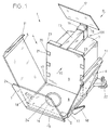
図1による秤は、秤の作動装置の一部を収容した床区画2を有する固定部と、駆動機構を収容したハウジング3と、計量区画4を有する。後壁9と、計量区画4の床8は、固定部で形成されている。計量区画4は、ドラフトシールドの役目を果たし、さらに側壁5、6と、前壁7と、上部カバーパネル12で囲まれている。床8は、計量皿10の受け部が通る開口部を有する。しかし、計量皿は、並行するスイス特許出願CH−1957/00が開示しているように、計量区画の後壁を通るカップリング機構に接続されたL字形カンチレバーアームによって支持してもよい。上記特許出願に開示されている計量皿の別の設計および/または計量区画の特徴も、同様に本発明の秤に適用可能である。
【0020】
秤1は、三本の脚22で支持するのが好ましい。
【0021】
側壁5、6と、前壁7と、上記カバーパネル12は、透明の材料好ましくはガラスから成る。特に悪い環境で秤をより安全に使用できるようにあるいは壁の取扱いにあまり神経を使わずにすみ、たとえば機械で洗浄することができるように、強化ガラスを用いてもよい。
【0022】
側壁5、6と上部カバーパネル12は、たとえばコードを引く(プルコード)駆動方式など、計量区画の開閉を行う駆動機構によりスライド可能である。側壁5、6のそれぞれと上部カバーパネル12は、案内装置17、120と一体に形成されたホルダーにより案内装置17、120に着脱可能に接続されている。前壁7も、ホルダー要素19により、同様に着脱可能に接続されている。
【0023】
側壁5、6と、前壁7と、上部カバーパネル12は、わずかに傾ければ、ホルダーから簡単に取り外して清掃できる。
【0024】
側壁5、6と上部カバーパネル12は、開放状態において、ハウジング3を囲んでいる。これが可能なのは、ハウジング3の幅と高さが計量区画4より小さいからである。
【0025】
側壁5、6と上部カバーパネル12の案内装置17、120は、側壁5、6と上部カバーパネル12を駆動機構のプルコードに接続するカップリング要素(図示せず)を有する。側壁5、6はそれぞれ、上部カバーパネル12と同様に、カップリング要素のための別々のアクチュエータハンドル18を有する(カバーパネルのそれは図1には示さない)。カップリング要素と駆動機構の機能は以下に述べる。これにより、側壁5、6と上部カバーパネル12を、別々にあるいはどれか二つを組み合わせてあるいは全部同時に、開閉することができる。
【0026】
秤1は、ハウジング3の上部に支持ハンドル13を備えている。このハンドル13は、持ち運び用だけでなく、上部カバーパネル12の開閉用の案内トラックとしても使われる。案内装置120の案内要素14は、この案内トラックに沿って動く。上部カバーパネル12は、ホルダー15を介して案内要素14に接続されている。上記のとおり、上部カバーパネル12のホルダー15は、たとえば清掃のために上部カバーパネル12を単に傾けるだけで取り外せるように設計されている。
【0027】
側壁5、6の上縁部は、この上縁部をスナップ留め式閉鎖要素(図1には示さず、図6参照)で保持する内側に傾斜した縁取り部材11で縁取られており、後壁9と前壁7の傾斜したコーナー部分23、24にそれぞれ載っている。縁取り部材11の傾斜した部分は、外気に対する一種のバッフルシールを形成するように側壁5、6と上部カバーパネル12の上縁部にそれらが互いに形が異なっていても重なり合うことができ、計量区画への風の侵入を普通のドラフトシールドよりも効果的にブロックすることができる。縁取り部材11は透明な材料で形成するのがより好ましい。
【0028】
たとえば側壁5、6の後縁部と前縁部および前壁7の側縁部と上縁部などの縁部を特殊な形状に形成し、計量区画4へ風が侵入する可能性をさらに小さくすると、さらに有益である。この構成は、二つの直角に交わる壁の一方に、他方の壁が嵌まる長方形の断面を有する溝182を設ければ実現できる。この例として、前壁7が側壁6と交わる縁部183を図2aに示す。あるいは、直角に曲がった縁部カバー材180が壁の縁部を全長にわたってカバーし、この部材が取り付けられる壁厚より長く延びることにより、計量区画が閉鎖されている状態で二つの壁の間に隙間181があってもこの縁部カバー材180でその隙間を閉鎖するようにしてもよい。縁部カバー材は、計量区画4の内部の見通しが悪くならないように透明のプラスチック製としてもよい。図2bは、図2aと同じ縁部を示しているが、計量区画4の縁部が有する別の構造を備えている。言うまでもなく、壁5、6、12の一つを傾けて各ホルダーから抜き出すためには、まず壁を少し開けて溝から引き出すか縁部カバー材がカバーしている範囲から引き出す必要がある。
【0029】
図3a〜3cは、前壁7が床区画2に取り付けられた状態からどのように取り外されるかを示している。前壁7を着脱する機構は、もちろん、側壁5、6と上部カバーパネル12の着脱にも用いられる。図3cからわかるように、ホルダー要素19の一部は、前壁パネル7の下縁部に取り付けられている(図1も参照)。このホルダー要素19は、底部にフォーク状凹部50を有する。ホルダー要素19の上部には突起49があり、突起49の背後には切込み47がある。突起49は、ホルダー要素19の固定部である。前壁7を取り付けるためには、フォーク状凹部50を床区画2の壁に設けたロッド48に嵌める(図3b)。次に、ロッド48を中心にして前壁7を反時計回りに回動させ、図3aに示す位置まで動かす。ラッチレバー44を備えた板ばね45とローラ46が、床8の下側に配置されている。前壁7が図3bの傾斜位置から図3aの直立位置まで持ち上げられると、突起49の斜面がローラ46に係合し、ローラ46が突起49を乗り越えるところまでラッチレバー44が押し上げられ、図3aが示すように切込み47に嵌まる。その結果、前壁パネル7は、固定手段48、50の係合、および同時に固定手段48、50から離れた位置での固定手段47、46の係合により、所定の位置にしっかり保持される。図面と以上の説明からわかるように、前壁7(および計量区画4の他のパネル5、6、12)を所定の位置に保持するためには、クランプ式ホルダーを締めたり緩めたりするための特別な作動装置は必要ない。それゆえ、以上の説明から、図示したホルダー要素19と以下に説明するホルダー要素は、固定手段を用いずに動作位置にしっかり取り付けることができる。
【0030】
図3a〜3cに示したばねとクランプを用いた接続は、好ましい構成である。それはまず、清掃しにくい溝が不要だからであり、さらに、離して配置した二対の固定手段50、48と固定手段47、46を用いた接続が非常に強固だからである。しかし、図4と図5が示すように、多くの変形例が可能で、これらを実際に使用することも可能である。たとえば、図4の構成は、床区画2の壁に溝またはチャンネル51を設けている。チャンネル51の垂直方向の側面の一方または両方には、ストリップ材52が長手方向に嵌まる凹部が形成されている。ストリップ材52は、たとえばポリマーなどの適切な弾性材料で形成したリップ53を有する。リップ53は、水平に配置することも可能だが、図4が示すように下向きに配置するのが好ましい。前壁パネル7(または、同様に、側壁パネル5、6または上部カバーパネル12)はホルダー要素19´を有する。リップ53は、前壁パネル7の表面から突出しているホルダー要素19´の側面を押す。前壁パネル7がチャンネル51内に押し込まれると、リップ53は突出した側面の後端に嵌まる。前壁パネル7をチャンネル51から引っ張り出す時にリップ53によって加えられる抵抗の大きさは、克服しなけれならない摩擦の大きさを決定するリップの角度と寸法を変えることで簡単に調節できる。
【0031】
図5のチャンネル51´は傾いた側面54を有する。前壁パネル7がチャンネル51´内の所定の位置にセットされた後、前壁パネル7と傾いた側面54の間に一つかそれ以上の締めローラ55が、前壁パネル7を支持面56に対してしっかり押し付けるために挿入される。この接続の安定性は、支持面56の高さと、チャンネル51´の底面からのローラ55の高さによって決まる。
【0032】
前壁パネル7を取り付けるための上記の各構成は、側壁パネル5、6の取り付けにも使用することも可能であるが、図6〜図9に示す構成は、壁パネルを動作位置でしっかり締め付けた状態で、それぞれの案内装置17(図1参照)によりスライド可能であるという利点を有する。
【0033】
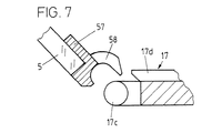
図6は秤1を正面から見た図であり、計量区画の後壁9を示す。左側の側壁パネル5は解放位置にある一方、右側の側壁パネル6は取付位置にあって案内装置に接続されている。案内装置17は、案内チャンネル17aと支持面17bを有する。
【0034】
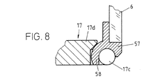
図7(図6の部分VIIの拡大図)と図8(図6の部分VIIIの拡大図)が示すように、案内装置は(図6の見る方向に対して)その前端と後端に円筒形のピボットピン17cを有する外向きの突起17dを備えている。ピボットピン17cの後方には十分な余地があり、このピボットピン17cにより鉤形の蝶番部58を係合できる。蝶番部58は、側壁パネル5に取り付けられた縁部ストリップ57の構成要素である。同様の構成が側壁パネル6においてもとられる。図7は、縁部ストリップ57の中央部分の断面を示しており、縁部ストリップ57の両端には、ピボットピン17cを有する上記の突起17dの位置に対応して蝶番部58がある。図8は、鉤形の蝶番部58の一つがピボットピン17cに係合している状態を示す縁部ストリップ57の端部の断面を示す。
【0035】
計量室の床8の下側に二対の固定手段50、48と47、46を取り付けるという図3の設計思想と異なり、図6〜図9が示す側壁パネルのホルダーの構成では、二対の固定手段の一方を壁パネルの上部で、図6のように後壁9の前側か、あるいは後側に取り付けている。
【0036】
第二の固定手段の対(図6の部分IX、図9に拡大して示す)は、好ましくは一体に射出形成されたポリマー製の部品であるフレーム状のスナップ留め式閉鎖部材59を備えた、特殊な設計のスナップ留め式閉鎖装置125を用いている。スナップ留め式閉鎖部材59は、ほぼ水平に延びる舌部61を有するほぼ垂直な支持部60を有する。舌部61はスナップ留め式閉鎖部材59を回転自在に支持する支点穴62を有する。しかし、回転範囲は、後壁9に取り付けられ舌部61の動きを制限するボルト64で制限される。ばね部材63が、舌部61から舌部61とほぼ平行に延び、ボルト64を押し付けている。ばね部材63は比較的硬いので、スナップ留め式閉鎖部材59が時計回りに回転しようとするのに抗する。舌部61に加え、二本の平行な弾性を有するアーム68が支持部60から水平に延び、支持部60の反対側で垂直脚部67により互いに接続されている。支持部60と垂直脚部67に近い水平アーム68の端部は、舌部61に近いばね部材63の屈曲部より薄くかつ長く形成することにより、一対の水平な弾性アーム68がばね部材63より弱い弾力を有するようにするのが好ましい。
【0037】
垂直脚部67は上向きに延びて、傾斜した上部70を有するポスト69を形成している。傾斜した上面70は、対向位置にある縁取り部材11の傾斜面71と協働する。縁取り部材11は、側壁パネル5、6の上端に取り付けられており(図1と図6参照)、好ましくは透明な材料で形成されている。側壁パネル5、6の蝶番部58を、図6の左部分(および部分VIIの拡大図である図7)が示すようにピボットピン17cに係合させ、次に図6の右部分が示すように直立した閉鎖位置までパネルを回動させると、対向位置にある傾斜面71がポスト69の傾斜した上部70に沿って滑ることにより、スナップ留め式閉鎖部材59に力を加える。スナップ留め式閉鎖部材59に加えられる水平方向の分力は、後壁9に吸収される。垂直脚部67とポスト69を有する弾性アーム68は、垂直方向の分力を受けて下向きに撓み、対向傾斜面71が傾斜した上部70を乗り越えて、ポスト69が対向傾斜面71の後方の溝72に係合するまで動く。これは、図9が示すように、スナップ留め式閉鎖装置125が係合した状態である。
【0038】
ポスト69を対向傾斜面71の後方の溝72にスナップ留め式に係合させるためには、アーム68のばね力が弱いため比較的小さな力しか必要としないが、この係合状態を解除するためにはかなり大きな力を要する。側壁パネル6が図6の右部分が示す垂直位置から蝶番部17c、58を中心にして時計回りに引っ張られるとき、溝72の左側の垂直側面がポスト69を押す。水平に押す力が支点穴62に対し偏心的にかかるとき、スナップ留め式閉鎖部材59にトルクが加わる。しかし、水平方向に押す力は短いレバーアームを有しているうえに、ばね部材63からさらに抗力が加わることもあり、支点穴62を中心として閉鎖部材59を回転させるためには比較的大きな力を要する。スナップ留め式閉鎖部材59に加わるトルクが十分大きくなると、スナップ留め式閉鎖部材59がばね部材63の力に抗して支点穴62を中心として反時計回りに回転し、平行移動しかできないように制限されているポスト69が溝72から外れることにより、側壁パネル5、6が解放される。支え穴62より上方にあるスナップ留め式閉鎖部材59の当接面65が後壁9の上縁部に当接しているので、側壁が外れた後にばね部材63が反対方向に戻り過ぎるのを防ぐ。もちろん、ばね部材63の代わりに、たとえば磁性要素などの力発生装置を用いることも考えうる。しかし、ばね部材63をスナップ留め式閉鎖部材59と、特に射出成形によって一体に形成すれば、製造コストを抑えられるので、ばね部材63を用いる構成が好ましい。
【0039】
この構成の利点は、壁パネルの取り外しより取り付けのほうが小さい力で行えることと、案内装置17による側壁5、6の移動が溝72に係合したポスト69により確実に案内されることにある。言うまでもなく、「左」「右」「上」「下」という言い方は相対的なものである。たとえば、図6が示す二つのスナップ留め式閉鎖部材59は対称の位置にあるので、この左右の位置関係は反対にもできる。また、スナップ留め式閉鎖部材59は、製造の観点では射出成形で一体に形成するのが好ましいが、複数の部品で組み立ててもよい。また、二つの弾性アーム68で脚部67を平行に案内する構成ではなく、単一の弾性アームを用いてもよいが、この場合、ポスト69は、より大きな水平方向の遊びを溝72の中で必要とするため、溝に係合したポスト69が同じ精度で案内することはできなくなる。また、ポスト69を脚部67の別の部位か弾性アーム68に接続し、一本か複数のポストをスライドする壁パネルに接続し、溝を固定部に設けることによってポスト69と溝72の関係を逆にすることも考えられる。
【0040】
図10は、図1の矢印IIの方向から見た秤において、ハウジング3の一部を切り欠いて、計量区画4を閉鎖した状態を示す。側壁5、6と上部カバーパネル12は、手動または動力で、好ましくは単一のモータ28で、別々か一緒に動かすことによって、計量区画の両方か片方の側面および/または上面を、任意の状況で必要に応じて開閉可能である。図10は、特に、パネル5、6、12を動かすための駆動機構を示しており、この駆動機構は三つのレベル25、26、27と別のレベル36に設けられている。この実施例の駆動機構は、コード・プーリ式駆動装置である(その詳細は、図15について説明する)。レベル26にある上側のコード・プーリ式駆動装置(図示せず)は上部カバーパネルを移動させ、レベル36にある下側のコード・プーリ式駆動装置(図示せず)は側壁5、6を動かす。
【0041】
図10は、さらに、上部カバーパネル12の案内機構を示す。支持ハンドル13は、支持ハンドル13に沿って動く上部カバーパネル12のホルダー15の案内要素14のための案内レールの役目も果たす。支持ハンドル13は、接続材34を介してレベル26に接続されている。ハウジング3の二つの保持部材32(図10は取り外した状態を示す)は、接続材34と後壁9の間に配置されている。案内要素14の下部33は、保持部材32の下方に配置され、狭いコネクタ41を介して上部カバーパネル12のホルダー15に接続されている(詳細は図13が示す)。
【0042】
コードカプラーレバー16は、上部カバーパネル12を上側のコード・プーリ式駆動装置38に接続したり離したりする(図14参照)。
【0043】
図11は、秤1の床区画2の断面を示す。参照記号42は秤1の計量部を示し、この計量部には計量皿10が公知の仕方で取り付けられている。上記のとおり、秤の別の構成では、計量部42もハウジング3内部に収容してもよく、計量皿をL字形支持部材で計量部42に取り付けてもよい。
【0044】
計量部42の両側で床区画2に接続された固定部品として、案内要素43が秤1の全長にわたって延びている。案内要素43は、上縁部の外側に、案内装置17の案内チャンネル17aに係合した四角形の突起150を有する(図11の左部分に示す)。
【0045】
案内要素43の長さの一部だけをカバーする別の案内チャンネル151が、案内要素43の底面に形成されている。チャンネル151には、ボルトブラケット40aで案内装置17に接続された案内ボルト40が係合している。案内ボルト40の位置と、この案内ボルトに対する案内チャンネル151の位置と長さが、案内チャンネル151内の案内ボルト40の移動範囲を決める。案内要素43の他の凹部または空洞は、側壁5、6を動かす役目を果たす下側のコード・プーリ式駆動装置39用のものである。
【0046】
側壁5、6の案内装置17は、クラッチアクチュエータ18で動作する爪ロック式側壁カプラー119(図11の右部分と図12に示す)を介して、コード・プーリ式駆動装置39に対して着脱される。レバー18は、ばね要素155のための二つの爪ロック位置156を有する。側壁は、レバー18が直立位置にあるとき、コード・プーリ式駆動装置に接続される。レバー18が傾斜位置まで押されるとき、ばね要素155が下側の爪ロック位置156に係合し、曲がったレバー要素153にロッド152が押し付けられ、レバー要素153がピボット軸157を中心に揺動し、移動カプラー要素106からカプラーばね154が持ち上げられる。このことは、図12a〜dに詳しく示す。図12aは、移動カプラー要素106を斜めから見た図である。図12bは、曲がったレバー要素153とカプラーばね154を備えたカプラー要素を真上から見た図である。図12cと図12dは、係合位置(図12c)と非係合位置(図12d)にあるカップリング機構を横から見た図である。
【0047】
コード・プーリ式駆動装置39に固定され、コードを溝158に保持している移動カプラー要素106は、その両端部から中央部の方へ高くなる傾斜路107、107´を有する。カプラーレバー18が係合位置にある場合、移動カプラー要素106がその移動範囲に沿って異なる位置にあったとしても、カプラーばね154の舌159がまず傾斜路107か107´の一方で押し上げられ、続いて二つの傾斜路の間にある切込み108に嵌まるので、移動カプラー要素106は、コード・プーリ式駆動装置が動いている間に、自動的にカプラーばねに接続される。側壁5、6は、それぞれコード・プーリ式駆動装置に接続されると、自動的に所望の位置へ移動する。接続されていない状態では、側壁5、6は手で動かすこともできる。カプラー要素106は、案内装置17の案内レールに沿って動く溝チャンネル141を有する。
【0048】
図13は、上部カバーパネル12(図示せず)の案内装置120の断面を示す。案内要素14の本体78は、側方に突出した隆起79を有しており、この隆起にプレート77がねじ80で取り付けられている。プレート77の上部(図示省略)は、上部カバーパネル12のホルダー機構15(図示せず)に接続されている。案内要素14の本体78の上部は、支持ハンドル13に囲まれている。支持ハンドル13の内部と中央から左寄りのところに、上側のギヤ73aに係合する上側のギヤラック73がある。同様の構成が、案内要素14の下部33において、下側のギヤラック74と下側のギヤ74aに用いられている。ギヤ73aと74aは、垂直ギヤシャフト66によって互いに接続されている。横方向に遊びが生じないように、上側のギヤ73aと下側のギヤ74aのそれぞれの隣に案内ローラ75と76が配置され、案内要素14が常にまっすぐ進み、支持ハンドル13と正しく位置合わせされている。案内要素14に加わる垂直方向の力は、滑り要素124で受け止められる。しかし、案内要素14は、一個か複数のローラ上を進むようにしてもよい。案内要素14の下側の底面は、図16に示す構成によって、上側のコード・プーリ式駆動装置38に接続されている。案内要素14の本体78は、コード・プーリ式駆動装置38によって、ギヤラック73、74に沿って移動される。案内要素14の本体78の狭いコネクタ部分41は、ハウジング3の二つの縁取り部材32の間にあるスロット81を通る(図10も参照)。スロット81は、薄膜、シールリップ、ブラシなどを重ね合わせて、埃が入らないようにシールしてもよい。
【0049】
図14は、図10と図13を補足するもので、上部カバーパネル12の駆動機構を横から見た図である。駆動源は、図10が示すように、レベル25と26の二段に配置されているが、モータ28は図示されていない。カプラーレバー16は、支持ハンドル13の後端部に配置され、ギヤ82とプーリ29との接続を着脱するクラッチ118(図示せず)を制御し、上部カバーパネルとモータ28とが選択的に接続または非接続状態になるようにしている。コード・プーリ式駆動装置が前進および後退できるようにするためにモータ28を可逆モータとするか、可逆ギヤボックスを用いてもよい。ギヤボックスは手動で逆回転させてもよく、あるいは、案内要素14が終端部に達したとき逆方向に転ずるように電気リミットスイッチのごとく作動するアクチュエータを設けてもよい。駆動力は、スパーベルトによりモータ28からギヤ30へ伝導され、ギヤ30は、ピニオンギヤ89を介してギヤ82を駆動する。
【0050】
図面からわかるように、レベル26は高い柱83に載る水平プレートで形成され、レベル25は短い柱84によりレベル26で支持された小さい方のプレートで形成されている。下側のギヤラック74は、簡単に図示したように、柱85(一方だけを図示)によりレベル26で同じように支持してもよい。下側のギヤラック74と、上側のギヤラック73(図13が示すように、支持ハンドル13の内部に設けられている)と、接続材34と、後壁9は、一緒になって、スライド可能な上部カバーパネル12を正確に位置合わせする硬いフレームを構成する。上部カバーパネル12はホルダー15に接続され、ホルダー15は、図10が示すように、プレート77によって案内要素14の本体78(図示せず)に接続されている。案内要素14の下部33は、下側のギヤラック74に沿って案内される。ピン状コネクタ86が、案内要素14の下側から突き出ており、案内要素14を上側のコード・プーリ式駆動装置38に接続する役目を果たしている。コードはプーリ29、87、88で案内されており、公知の仕方で駆動プーリ29の周囲に巻き付けられている。駆動プーリ29は、たとえばボールベアリング90上で支持してもよい。
【0051】
スパーベルト(図10参照)を介してモータ28で駆動されるギヤ30は、シャフト35を介してピニオンギヤ89に接続される(図14)。シャフト35は、組み立てと分解の際、上方から簡単に挿入と取り外しが可能なように設計されている。ピニオンギヤ89は、位置を上下させることが可能であるシャフト91に取り付けられたギヤ82に噛み合う。シャフト91の位置をギヤ82と一緒に変更することにより、ギヤ82がプーリ29につながったり離れたりする。ギヤ82とプーリ29のクラッチは公知のさまざまな構成に従って設計すればよいが、図12の思想に類似のロックばね要素を備えた傾斜路92の構成を用いるのが好ましい。ギヤ82とプーリ29のクラッチは、ギヤ82とプーリ29の間の狭いスペースに位置しているので、連結ばねの位置決め爪は、上端面が傾斜した二つのボルトで形成される。
【0052】
上部パネルクラッチ118は、図10の説明で既に示したクラッチレバー16で作動する。オペレータはレバー16を操作することにより、上部カバーパネル12を手で動かすか、あるいは上部カバーパネル12を動かさずに側壁5、6だけを動かすためにプーリ29とモータ付き駆動装置28、82との係合を選択的に解除することが可能である。クラッチレバー16は、接続材34で保持された軸94を中心にレバー16と一緒に回転するカムディスク93に接続されている。プッシュロッド95は、接続材34の内部で垂直方向に動くように案内されている。二つのアームを有するレバー97は、ロッド95を上向きに押し、カムディスク93に押しつける。
【0053】
二つのアームを有するレバー97は、ギヤ82が取り付けられているシャフト91の下端を支えている。レベル25に取り付けられたばね98が、シャフト91の上端を押し、シャフト91を下向きに付勢してレバー97のアームの一方に押し付けている。このことにより、支点穴96の反対側にあるレバーアームは、ロッドを上向きに押し、カムに押し付ける。したがって、クラッチレバー16を反時計回りに動かすと、カム93がロッド95をばね98の力に逆らって下向きに押し、二つのアームを有するレバー97を時計回りに傾ける。これにより、他方のレバーアームがシャフト91をギヤ82とともに持ち上げるので、ギヤ82とプーリ29の係合が外れる。ギヤ82は、非係合位置において、ピニオンギヤ89と噛み合っている。手動によるクラッチの代わりに、たとえば電磁式作動部材により、自動にしてもよい。
【0054】
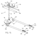
図15は、上部コード・プーリ式駆動装置38と下部コード・プーリ式駆動装置39を備えた駆動装置の全体を示す。スパーベルトのモータ28とギヤ30は示されていない(図10参照)。ピニオンギヤ89は、軸受102、103に支持された駆動シャフト35に接続されており、下側のコード・プーリ式駆動装置39に駆動運動を伝達する。上側の駆動装置38のコードは、図示されているように、駆動プーリ29の全周にループ状に巻き付けられ、続いてプーリ87、88の周囲を通り、駆動プーリ29に戻る。プーリ87とプーリ88の間にあるコードの直線部分は、上部カバーパネルの案内装置の案内要素14の底部に接続されている(図14参照)。この接続は、固定手段86により適当な部位で行われている。固定手段86の好ましい設計は図16が示しており、これについては以下に説明する。
【0055】
シャフト35の下端に取り付けられたピニオンギヤ104は、プーリ105に固定されているギヤ99を介して下側のコード・プーリ式駆動装置39を駆動する。上側のコード・プーリ式駆動装置38と同様に、上側の駆動装置39のコードは、図示されているように、駆動プーリ105の全周にループ状に巻き付けられ、続いてプーリ100、101の周囲を通り、駆動プーリ105に戻る。プーリ100とプーリ101の間にあるコードの直線部分は、側壁5、6を動かす移動カプラー要素106に接続されている(図12a〜12d参照)。
【0056】
すでに述べたように、図16はコードの取り付け方法の例を示すもので、図16aは側方から見た状態で、図16bは正面から見た状態で示している。取付装置は、コード38を受けるスロット111を有する本体117から成る。取付装置の本体117上部の内側には、ねじ山が切られている。取付装置の本体117にスリーブ110がかぶせられ、ねじ116がスリーブでコードを固定できるだけ十分深くねじ山にねじ込まれている。
【0057】
側壁5、6と上部カバーパネル12は、すでに述べたように、単一のモータ28によりスライド可能である。秤の構成の仕方によっては、壁5、6、12は、それぞれの開位置から閉位置まで、異なる距離を移動する場合がある。たとえば、上部カバーパネル12の移動距離が、側壁5、6より長い場合もあれば、短い場合もある。コード・プーリ式駆動装置38、39を備えた駆動装置の構成と、複数のギヤを介したモータとの接続により、設計に融通性が生まれ、それぞれに応じた伝導率を簡単に設定することが可能であるので、側壁5、6と上部カバーパネル12は、駆動装置に接続されたとき同期して動く。
【0058】
また、オペレータが側壁5、6または上部カバーパネル12の適当な場所を手で押して所望の方向へ動かそうとするとき、側壁5、6と上部カバーパネル12の所望の移動方向を認識するように駆動機構を設計してもよい。たとえば、クラッチアクチュエータ18、16が係合状態で押されたり引かれたりする場合、移動方向をセンサで検出して、所望の方向への移動のためにモータを作動するようにしてもよい。また、CD−ROMドライブが押す力に反応して閉まるように、側壁5、6と上部カバーパネル12が、閾値を越える力で押されたときに動き始めるようにしてもよい。
【0059】
図1ですでに示したように、計量区画の後壁9は、ハウジング3より幅広で背も高い。このことにより、後壁(図1参照)の両側と上縁に沿って切欠開口部20を設けることが可能である。切欠開口部20は、クリップ留め式カバー21で閉鎖しておいて、たとえばクリップ留め式カバー21を一つまたは複数の切欠開口部20から取り外し、電線および/または計量対象の液体を通す管などの供給ラインの通路として使うこともできる。このようにすれば、実験を計量区画の内部で行うと同時に、計量区画を解放して計量エラーの発生のリスクを冒す必要なく重量の変化を観察することが可能である。もちろん、切欠開口部20は、側壁5、6および/または上部カバーパネル12に設けてもよい。
【0060】
図17は、後壁9に設けた切欠開口部20を上から見た図であり、その使い方の例を示す。切欠開口部は通常、風が入らないようにクリップ留め式カバーで閉鎖されているが、クリップ留め式カバーを取り外して、開口部を導管やホースなどの通路として使用することも可能である。図17は、液体を容器121から切欠開口部20を通る導管123を介して計量用容器122に供給する例を示す。切欠開口部20を完全に開いたままにするかわりに、特別なU字形クリップ留め式装置21′(詳細図A参照)を用いて導管をよりしっかり保持するようにしてもよい。
【0061】
図18は、切欠開口部20に挿入されるクリップ留め式装置の別の使い方として、計量区画4の内部まで延びる器具ホルダー130を備えたクリップ留め式装置21″の例を示す。このように取り付けられた器具ホルダー130は、導管、管、温度計131および/または計量区画4の内部で実験を行う際に必要なあらゆる種類の用具を融通のきく取り外し可能な状態に配置するために用いることができる。
【0062】
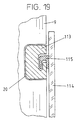
切欠開口部の別の例を図19に示す。側壁114の高さが異なる秤の構成を用いることが可能である。本発明による駆動機構で異なる高さの側壁パネル114を動かすためには、壁パネル114の上部に案内を設ける必要がある。この構成は、切欠開口部20に挿入された適当なクリップ留め式装置113を用いることにより実現する。壁パネル114にはクリップ留め式装置113でスライド可能に案内されたホルダーレール115が接続されている。もちろん、秤からのパネル114の取り外しは、すでに述べた壁パネル5、6の取り外しと同様に単純な方法で行える。
【0063】
図20が示すように、付属品ユニット140を、たとえばローレットヘッドねじなどの単純な固定手段により、秤の後部に取り外し可能に取り付けてもよい。付属品ユニット140は、電池のような電源ユニットや電子制御モジュールを有していてもよい。付属品ユニット140は、さまざまな種類のコネクタのための開口部147を有している。このことにより、計量区画4内部の供給装置などの実験装置を付属品ユニット140と電気的に接続できる。電線や導管は、クリップ留め式装置21′に類似した特別なクリップ式ホルダーが設けられている切欠開口部20から計量区画4に挿入される。電線や、図17の導管123のような導管が、ハウジング3に沿ってスライド移動する側壁5、6の邪魔にならないように、後壁9は、ハウジング3の両側に案内チャンネル143を取り付けるための凹部142を有している。さらに、案内チャンネルは、付属品ユニット140のホルダー側壁144のスロット148により、所定の位置に保持されている。案内チャンネル143は、たとえば金属製やポリマー材料製としてもよい。図20が示すように、案内チャンネルは、さまざまな設計をとることが可能である。たとえば、案内チャンネル143′の上部を覆うことにより、チューブ状にしてもよい。また、案内チャンネルは、ハウジング3に取り付けられ一つのまたは複数の切欠開口部20の上を延びる側面取付モジュールとして設計してもよい。さらに、特に付属品ユニット140を有していない実施例において、案内チャンネルの中に単純な電子モジュールまたはモジュールの一部を配置するようにしてもよい。
【0064】
案内チャンネル143は、側壁5、6が自由に移動できるのに適した幅より広くしてはならない。案内チャンネル143の両端は、案内チャンネルを後壁とホルダー装置144にそれぞれ取り付けるためのコネクタ145、146になっている。この構成の利点は、たとえば前述の特許出願CH−1957/00などに詳しく開示された種類の実験装置が計量区画4の内部で供給を受けて作動しているとき、計量区画4を外部に対して閉鎖したままにすることができる点にある。
【0065】
もちろん、基本的に駆動機構で占められているハウジング3と、付属品ユニット140とを、共通のハウジングにまとめて収容してもよい。導管と電線のための案内チャンネル143をこの共通のハウジングの側壁に一体に形成し、特別なカバーで外部から閉鎖してもよい。
【図面の簡単な説明】
【図1】本発明による秤の正面図
【図2】2aと2bは、二つの壁が係合する区域における計量区画の縁部の断面図
【図3】3a〜3cは、三つの異なる位置における計量区画の前壁の取り付け状態を示す断面図
【図4】壁の取り付けの第一の構成の断面図
【図5】壁の取り付けの第二の構成の断面図
【図6】図1の矢印VIの方向から見た計量区画を示す図
【図7】図6の細部VIIを示す図
【図8】図6の細部VIIIを示す図
【図9】図6の細部IXを示す図
【図10】図1の矢印IIの方向から見た秤の斜視図(ハウジングを外した状態)
【図11】正面から見た秤の下部の詳細図
【図12】12a〜12dは、異なる方向から見た側壁のカプラー要素を示す図
【図13】上部カバーパネルの案内機構と駆動機構の断面図
【図14】上部カバーパネルの駆動機構の側面図
【図15】駆動機構全体の略図
【図16】16a、16bは、コードの固定方法を側面(16a)と正面(16b)から見た図
【図17】後壁の開口部の使用例を示す図(上側から見た図)
【図18】クリップ式要素の使用例を示す図(正面から見た図)
【図19】低くした壁パネルを用いた秤の実施例においてクリップ式要素の使用例を示す図(断面図)
【図20】付属品ユニットとホルダー装置と案内チャンネルを取り付けた状態で後方から斜めに見た秤を示す図(三次元的に示す図)
【符号の説明】
1 秤
2 床区画
3 ハウジング
4 計量区画
5 側壁パネル
6 側壁パネル
7 前壁パネル
8 床
9 後壁
10 計量皿
11 縁取り部材
12 上部カバーパネル
13 支持ハンドル
14 案内要素
15 上部カバーパネルのホルダー要素
16 カプラーレバー
17 案内装置
17a 案内チャンネル
17b 支持面
17c ピボットピン
17d 突起
18 アクチュエータハンドル
19、19´ 前壁パネルのホルダー
20 切欠開口部
21、21´、21″ クリップ留め装置
22 脚
23、24 傾斜したコーナー部分
25、26、27 レベル
28 モータ
29 プーリ
30 スパーベルトギヤ
32 保持部材
33 案内要素の下部
34 接続材
35 回転シャフト
36 レベル
38 上側のコード・プーリ式駆動装置
39 下側のコード・プーリ式駆動装置
40 案内ボルト
40a ボルトブラケット
41 接続部
42 計量部
43 案内要素
44 ラッチレバー
45 板ばね
46 ローラ
47 切込み
48 ロッド
49 突部
50 フォーク状凹部
51、51´ チャンネル
52 ストリップ材
53 リップ
54 傾いた側面
55 ローラ
56 支持面
57 縁部ストリップ
58 蝶番部
59 スナップ留め式閉鎖部材
60 支持部
61 舌部
62 支点穴
63 ばね部材
64 ボルト
65 当接面
66 垂直ギヤシャフト
67 垂直脚部
68 弾性を有するアーム
69 ポスト
70 ポストの傾斜した上面
71 対向傾斜面
72 溝
73 上側のギヤラック
73a 上側のギヤ
74 下側のギヤラック
74a 下側のギヤ
75 上側の案内ローラ
76 下側の案内ローラ
77 プレート
78 案内要素の本体
79 隆起
80 ねじ
81 スロット
82 ギヤ
83 高い柱
84 短い柱
85 柱
86 固定手段
87 プーリ
88 プーリ
89 ピニオンギヤ
90 ボールベアリング
91 シャフト
92 傾斜路
93 カムディスク
94 軸
95 プッシュロッド
96 支点穴
97 二つのアームを有するレバー
98 ばね
99 ギヤ
100 プーリ
101 プーリ
102 軸受
103 軸受
105 プーリ
106 移動カプラー要素
107、107´ 傾斜路
108 切込み
110 スリーブ
111 スロット
113 クリップ留め式装置
114 側壁パネル
115 ホルダーレール
116 ねじ
117 取付装置の本体
118 上部カバーパネルのクラッチ
119 側壁カプラー
120 案内装置
121 容器
122 計量用容器
123 導管
124 滑り要素
125 スナップ留め式閉鎖部材
130 器具ホルダー
131 温度計
140 付属品ユニット
141 溝チャンネル
142 凹部
143、143´ 案内チャンネル
144 ホルダー装置
145 コネクタ
146 コネクタ
147 付属品ユニットの開口部
148 スロット
150 突起
151 案内チャンネル
152 ロッド
153 曲がったレバー要素
154 カプラーばね
155 ばね要素
156 爪ロック位置
157 ピボット軸
158 溝
159 舌部
180 縁部カバー材
181 隙間
182 溝
183 縁部[0001]
BACKGROUND OF THE INVENTION
The invention comprises a weighing compartment in contact with the fixed part of the scale, the weighing compartment being surrounded by at least one side wall, a front wall and an upper cover panel, at least one wall and / or top cover for opening and closing the weighing compartment The present invention relates to a scale in which a panel is slidable by a guide device.
[0002]
A known scale of this type comprises a weighing pan and a weighing compartment that surrounds the weighing pan in all directions, as in the example described in European patent application EP-A-0 234 008, for example. And a side wall that slides backward, an upper cover panel that slides backward, and a connector that connects the side wall to the upper cover panel. The connector is configured to move together with the side wall and / or the upper cover panel when the side wall and / or the upper cover panel is opened and closed, and to freely access the measuring section without being obstructed by the side frame member. In addition, the side walls can be opened and closed separately or together and simultaneously move with or separately from the top cover panel. Driving is done by motor or manually. When done manually, the wall to be moved is separated from the motor drive mechanism.
[0003]
European patent application EP-A-0 574 668 discloses a scale with a draft protective housing having a top cover panel that is removable with a manual locking device. After the top cover panel is removed, the front and side walls can be completely removed from the housing and cleaned. In this known construction of the balance, the top cover panel forms part of a frame that holds the draft protective housing together. To some extent, the frame member does not get in the way of the wall, so the operator can often look inside the scale, but for some applications this design is not sufficient. One of the disadvantages is that the upper part of the frame is a necessary element, and the locking element must be assembled with high precision, but it requires clever handling to align with the recess on the receiving side. It is.
[0004]
Prior art scales have at least partially opened a slidable side wall or top cover panel during the metering process when in a flexible and changeable configuration coupling means such as conduits or hoses have to be introduced into the metering compartment It was necessary to leave. This is because, if a rigid frame or a complicated guide device is used, it is not possible to provide individual easily accessible conduits on the wall. However, if the wall is left open, errors may occur in the weighing results.
[0005]
Basically, the known scales have the disadvantage that they cannot simultaneously access the weighing compartment and do not obstruct the view to the weighing pan. Access from the side and from the top cannot be performed simultaneously, and there is a problem in the accessibility to connections such as conduits and hoses. In addition, the weighing compartment is difficult to clean.
[0006]
OBJECT OF THE INVENTION
Accordingly, it is an object of the present invention to provide a scale that makes the weighing pan look unobtrusive and always has good accessibility in any situation. Further, this object is achieved by a simple idea that facilitates the user's operation. The weighing compartment must be easy to access to place the sample on the weighing pan with the walls open, and allow the conduits and cables to pass through even when the walls are completely closed. It must also be easy to clean without complicated operations.
[0007]
SUMMARY OF THE INVENTION
The present invention comprises a measuring section that is partially in contact with the fixed part of the scale, or is surrounded by at least one side wall, a front panel, and a top cover panel, the wall for opening and closing the measuring section A method for solving the above problems is proposed for a scale in which one of the upper cover panels is slidable by a guide device. According to the present invention, the mechanism for holding the at least one slidable wall panel is provided integrally with the guide device, and the mechanism for holding each of the fixed wall panels is provided integrally with the fixing portion of the scale. ing. Each wall panel is removably held in place by a corresponding holder, which engages a shape lock closure device that operates simply by applying a force to the wall panel and / or the holding mechanism; It can be locked and unlocked by releasing it.
[0008]
The side wall, the front wall, and the top cover panel can be separated from the scale if they are moved by hand and tilted slightly outward. For example, it is easy to clean a wall plate, which is usually made of glass. The side wall, front wall, and top cover panel are securely locked in place when in the activated position. To unlock each of these walls, push and move it as well. The structure in which the holder for the slidable wall is formed integrally with the guide device allows not only easy disassembly of the weighing compartment for cleaning, but also free access to the weighing compartment, and a frame member that blocks the view. As a result, the weighing pan can be seen unobstructed even when the weighing compartment is closed.
[0009]
At least one of the members constituting the holder comprises a snap-on closure member for automatically snap-connecting to each of the wall panels. The snap closure member is preferably attached to the rear wall of the metering section for holding and guiding the side wall.
[0010]
The idea of using at least one snap-on closure member, for example to hold the side wall in the operating position, is particularly preferred in designs that do not use a frame member. Such a support frame as required in the prior art is not necessary for the scale according to the invention. The snap closure member can be handled by hand, so that the wall can be attached by pushing the wall with the hand, and the wall can be removed by pulling with the hand. The snap-on closure member is designed to require greater force to pull out than to return the wall to place. The design of the snap-on closure member in a special shape and integrally molded as a plastic product is particularly cost-effective.
[0011]
Another embodiment of the scale according to the invention engages at the edge so that wind does not enter the engaging part connecting the walls of the weighing compartment, and the edge of one wall is fitted into the recess in the other wall. Or the gap formed in the engaging portion between the two walls is closed with an edge strip provided on one wall.
[0012]
A preferred embodiment of the scale has a drive means for the at least one slidable wall panel. This drive means is preferably a system in which the pulley is moved by a cord.
[0013]
The slidable wall is detachably attached to the guide device by a coupler or a clutch that allows the guide device of each wall panel to be attached to and detached from the driving means. Since the lever is attached to the coupler, it can be operated by hand. As a result, the sidewall panel and / or the top cover panel can be driven separately or together or in combination. For example, it can be opened and closed with only one side wall or top cover panel. The coupler mechanism preferably includes a movable coupler element that automatically detects the engaged position. For example, if the sidewall is away from the drive, pressing the coupler actuator on the sidewall will connect the sidewall to the drive as soon as the movable coupler element on the sidewall reaches the mating element on the wall panel.
[0014]
In the preferred embodiment of the invention, the drive is preferably operated by only one motor.
[0015]
According to another embodiment of the present invention, the moving distance between the open position and the closed position is made different between the upper cover panel and the side wall, and the respective driving devices are synchronized using the conductivity according to the different moving distance. May be. Therefore, the same motor may be used for driving the side wall and the upper cover panel.
[0016]
The scale is preferably provided with a support handle. Thus, for example, it is possible to lift the scale from the table with one hand and clean the table surface under the scale with the other hand. As a feature of the present invention, the support handle serves as a guide rail mounted on the handle as well as a guide rail for the guide element of the cover panel. In a preferred embodiment, at least one gear rack is provided at the top of the guide device and a parallel gear rack is provided at the bottom of the guide device. The vertical body of the guide element includes a pair of identical gears that are fixed on a vertical axis and rotate along the gear rack, so that the guide elements are held in alignment and are not caught when moving back and forth. By arranging the guide elements vertically in this way, the length of the guide device of the upper cover panel can be minimized.
[0017]
In a particularly preferred embodiment of the balance according to the invention, notch openings for the conduits and cables are provided in the side and front walls, the upper cover panel and / or the rear wall of the metering compartment. The cutout opening can be closed with a clip-on cover so that wind (air draft) does not enter. This concept is often used when conducting experiments in a weighing compartment and observing changes in weight as part of the experiment (for example, pouring reagents into a beaker placed on a weighing pan or examining chemical reactions). There is a possibility that it can be applied to other applications. Since there is no frame member along the edge and the wall can be tilted outward without removing it from the scale, the wire and cable or liquid or gas conduit is passed through the notch opening in a simple manner, It is possible to secure the cable and conduit within the notch opening and to close the notch passage using a special clip-on holder to prevent wind. For example, the special structure of the clip-on holder as a holder element allows it to be used in a wide range of applications.
[0018]
A special embodiment of the balance according to the invention comprises, for example, an auxiliary device at the rear of the balance. The auxiliary device includes a power supply device and / or a control device. The cable connected to this auxiliary device can be extended through a special guide channel along the housing to the notch passage so that the cable does not interfere with the movement of the side walls.
[0019]
Detailed Description of the Preferred Embodiment
The scale according to FIG. 1 has a fixed part having a
[0020]
The
[0021]
The
[0022]
The
[0023]
If the
[0024]
The
[0025]
The
[0026]
The
[0027]
The upper edges of the
[0028]
For example, the edges such as the rear edge and the front edge of the
[0029]
FIGS. 3 a to 3 c show how the
[0030]
The connection using springs and clamps shown in FIGS. 3a-3c is a preferred configuration. First, it is because a groove that is difficult to clean is unnecessary, and furthermore, the connection using the two pairs of fixing means 50 and 48 and the fixing means 47 and 46 that are arranged apart from each other is very strong. However, as FIG. 4 and FIG. 5 show, many variations are possible and these can be used in practice. For example, the configuration of FIG. 4 provides a groove or
[0031]
The
[0032]
Each of the above-described configurations for attaching the
[0033]
FIG. 6 is a front view of the
[0034]
As shown in FIG. 7 (enlarged view of part VII in FIG. 6) and FIG. 8 (enlarged view of part VIII in FIG. 6), the guide device is cylindrical at its front and rear ends (relative to the viewing direction of FIG. 6). There is an
[0035]
Unlike the design concept of FIG. 3 in which two pairs of fixing means 50, 48 and 47, 46 are attached to the lower side of the
[0036]
The second pair of securing means (part IX in FIG. 6, shown enlarged in FIG. 9) comprises a frame-like snap-on
[0037]
The
[0038]
In order to engage the
[0039]
The advantage of this configuration is that the attachment can be performed with a smaller force than the removal of the wall panel, and the movement of the
[0040]
FIG. 10 shows a state in which the weighing
[0041]
FIG. 10 further shows a guide mechanism for the
[0042]
The
[0043]
FIG. 11 shows a cross section of the
[0044]
As a fixed part connected to the
[0045]
Another
[0046]
The
[0047]
The moving
[0048]
FIG. 13 shows a cross section of the
[0049]
FIG. 14 supplements FIGS. 10 and 13 and is a view of the drive mechanism of the
[0050]
As can be seen, the
[0051]
The
[0052]
The
[0053]
A
[0054]
FIG. 15 shows the entire drive device including the upper cord / pulley
[0055]
A
[0056]
As described above, FIG. 16 shows an example of a method of attaching the cord, FIG. 16a shows a state seen from the side, and FIG. 16b shows a state seen from the front. The attachment device comprises a
[0057]
The
[0058]
Further, when the operator tries to move the
[0059]
As already indicated in FIG. 1, the
[0060]
FIG. 17 is a view of the
[0061]
FIG. 18 shows an example of a clip-on
[0062]
Another example of the notch opening is shown in FIG. It is possible to use a scale configuration with
[0063]
As FIG. 20 shows, the
[0064]
The
[0065]
Of course, the
[Brief description of the drawings]
FIG. 1 is a front view of a scale according to the present invention.
2a and 2b are cross-sectional views of the edge of the weighing compartment in the area where the two walls engage
FIGS. 3a to 3c are cross-sectional views showing the attachment state of the front wall of the measuring section at three different positions;
FIG. 4 is a cross-sectional view of a first configuration for wall mounting.
FIG. 5 is a cross-sectional view of a second configuration of wall mounting.
FIG. 6 is a diagram showing a weighing section viewed from the direction of arrow VI in FIG.
7 shows detail VII in FIG.
FIG. 8 shows detail VIII of FIG.
FIG. 9 is a diagram showing a detail IX in FIG. 6;
10 is a perspective view of the balance as seen from the direction of arrow II in FIG. 1 (with the housing removed).
FIG. 11 is a detailed view of the lower part of the scale as seen from the front.
FIGS. 12a to 12d show the coupler elements on the side walls as seen from different directions.
FIG. 13 is a cross-sectional view of the guide mechanism and drive mechanism of the upper cover panel.
FIG. 14 is a side view of the drive mechanism of the upper cover panel.
FIG. 15 is a schematic view of the entire drive mechanism.
FIGS. 16a and 16b are views of the fixing method of the cord as seen from the side surface (16a) and the front surface (16b).
FIG. 17 is a view showing an example of use of the opening of the rear wall (viewed from above).
FIG. 18 is a diagram showing an example of using a clip-type element (view from the front)
FIG. 19 shows an example of the use of clip-type elements in an embodiment of a scale using a lowered wall panel (cross-sectional view).
FIG. 20 is a view showing the scale obliquely viewed from the rear with the accessory unit, the holder device, and the guide channel attached (a three-dimensional view).
[Explanation of symbols]
1 scale
2 floor sections
3 Housing
4 Weighing compartment
5 Side panel
6 Side panel
7 Front wall panel
8 floors
9 Rear wall
10 Weighing pan
11 Border member
12 Top cover panel
13 Support handle
14 Guide elements
15 Holder element for upper cover panel
16 Coupler lever
17 Guide device
17a Information channel
17b Support surface
17c Pivot pin
17d protrusion
18 Actuator handle
19, 19 'Front wall panel holder
20 Notch opening
21, 21 ', 21 "clip fastening device
22 legs
23, 24 Inclined corners
25, 26, 27 levels
28 Motor
29 pulley
30 Spur belt gear
32 Holding member
33 Lower part of guide element
34 Connecting material
35 Rotating shaft
36 levels
38 Upper cord pulley drive
39 Lower cord pulley drive
40 guide bolt
40a bolt bracket
41 connections
42 Weighing section
43 Guidance elements
44 Latch lever
45 leaf spring
46 Laura
47 depth of cut
48 rod
49 Projection
50 Fork-shaped recess
51, 51 'channels
52 Strip material
53 Lip
54 Inclined side
55 Laura
56 Support surface
57 Edge Strip
58 Hinge
59 Snap closure closure
60 Supporting part
61 Tongue
62 fulcrum hole
63 Spring member
64 volts
65 Contact surface
66 Vertical gear shaft
67 Vertical leg
68 Elastic arm
69 post
70 Post sloped top surface
71 Opposing inclined surface
72 groove
73 Upper gear rack
73a Upper gear
74 Lower gear rack
74a Lower gear
75 Upper guide roller
76 Lower guide roller
77 plates
78 Body of guide element
79 Uplift
80 screws
81 slots
82 Gear
83 high pillar
84 Short pillar
85 pillars
86 Fixing means
87 pulley
88 pulley
89 Pinion gear
90 ball bearing
91 shaft
92 Ramp
93 cam disc
94 axes
95 push rod
96 fulcrum hole
97 Lever with two arms
98 spring
99 gear
100 pulley
101 pulley
102 Bearing
103 Bearing
105 pulley
106 Moving coupler element
107, 107 'ramp
108 notches
110 sleeve
111 slots
113 Clip-on device
114 Side panel
115 Holder rail
116 screw
117 Body of the mounting device
118 Clutch on top cover panel
119 Sidewall coupler
120 Guide device
121 containers
122 Weighing container
123 conduit
124 Sliding element
125 Snap closure member
130 Instrument holder
131 thermometer
140 Accessory unit
141 groove channel
142 Recess
143, 143 'guide channel
144 Holder device
145 connector
146 connector
147 Accessory unit opening
148 slots
150 protrusions
151 Information channel
152 Rod
153 Bent lever element
154 Coupler spring
155 Spring element
156 Claw lock position
157 Pivot shaft
158 groove
159 tongue
180 Edge cover material
181 Clearance
182 groove
183 edge
Claims (34)
Applications Claiming Priority (2)
| Application Number | Priority Date | Filing Date | Title |
|---|---|---|---|
| CH20001958/00 | 2000-10-04 | ||
| CH19582000 | 2000-10-04 |
Related Child Applications (2)
| Application Number | Title | Priority Date | Filing Date |
|---|---|---|---|
| JP2007216219A Division JP4764388B2 (en) | 2000-10-04 | 2007-08-22 | Scale with weighing compartment |
| JP2007216207A Division JP4620094B2 (en) | 2000-10-04 | 2007-08-22 | Scale with weighing compartment |
Publications (3)
| Publication Number | Publication Date |
|---|---|
| JP2002195874A JP2002195874A (en) | 2002-07-10 |
| JP2002195874A5 JP2002195874A5 (en) | 2007-11-22 |
| JP4145035B2 true JP4145035B2 (en) | 2008-09-03 |
Family
ID=4566916
Family Applications (3)
| Application Number | Title | Priority Date | Filing Date |
|---|---|---|---|
| JP2001299473A Expired - Fee Related JP4145035B2 (en) | 2000-10-04 | 2001-09-28 | Scale with weighing compartment |
| JP2007216219A Expired - Fee Related JP4764388B2 (en) | 2000-10-04 | 2007-08-22 | Scale with weighing compartment |
| JP2007216207A Expired - Lifetime JP4620094B2 (en) | 2000-10-04 | 2007-08-22 | Scale with weighing compartment |
Family Applications After (2)
| Application Number | Title | Priority Date | Filing Date |
|---|---|---|---|
| JP2007216219A Expired - Fee Related JP4764388B2 (en) | 2000-10-04 | 2007-08-22 | Scale with weighing compartment |
| JP2007216207A Expired - Lifetime JP4620094B2 (en) | 2000-10-04 | 2007-08-22 | Scale with weighing compartment |
Country Status (7)
| Country | Link |
|---|---|
| US (3) | US6686545B2 (en) |
| EP (3) | EP1312902B1 (en) |
| JP (3) | JP4145035B2 (en) |
| CN (2) | CN1233993C (en) |
| AT (2) | ATE324575T1 (en) |
| DE (2) | DE50109632D1 (en) |
| HK (1) | HK1046545B (en) |
Cited By (5)
| Publication number | Priority date | Publication date | Assignee | Title |
|---|---|---|---|---|
| JP2010266436A (en) * | 2009-05-13 | 2010-11-25 | Mettler-Toledo Ag | Draft protection device for laboratory instrument |
| JP2015152481A (en) * | 2014-02-17 | 2015-08-24 | アンリツ産機システム株式会社 | Weighing instrument |
| JP2019194575A (en) * | 2018-04-17 | 2019-11-07 | メトラー−トレド ゲーエムベーハー | Experimental balance including electric wind protection |
| JP2019215318A (en) * | 2018-04-17 | 2019-12-19 | メトラー−トレド ゲーエムベーハー | Experimental balance including electrically-driven slide top wall of windshield |
| JP2019219388A (en) * | 2018-06-07 | 2019-12-26 | メトラー−トレド ゲーエムベーハー | Weighing device comprising movable mounting unit |
Families Citing this family (43)
| Publication number | Priority date | Publication date | Assignee | Title |
|---|---|---|---|---|
| US6603081B2 (en) * | 2000-10-04 | 2003-08-05 | Mettler-Toledo Gmbh | Balance with a weighing compartment |
| US6686545B2 (en) * | 2000-10-04 | 2004-02-03 | Mettler-Toledo Gmbh | Balance with a weighing compartment |
| US6949710B2 (en) * | 2002-03-01 | 2005-09-27 | Bowe Bell + Howell Postage Systems Company | Mail weighing system and scale apparatus |
| DE10214954C1 (en) * | 2002-04-04 | 2003-09-04 | Mettler Toledo Gmbh | Precision weighing device with wind shield having sliding walls for opening and closing weighing chamber operated via pairs of grip elements |
| CN100359298C (en) * | 2003-11-07 | 2008-01-02 | 邓志明 | Food processor with weighing device |
| EP1617191B1 (en) * | 2004-07-16 | 2011-04-20 | Mettler-Toledo AG | Wind guard device for a balance |
| JP4403912B2 (en) * | 2004-07-30 | 2010-01-27 | 株式会社島津製作所 | Electronic balance |
| PL1674840T3 (en) * | 2004-12-23 | 2009-07-31 | Mettler Toledo Gmbh | Filling system in a balance |
| US7732720B2 (en) * | 2005-02-18 | 2010-06-08 | Ohaus Corporation Usa | Draft protection device for a balance and having a friction reduction device |
| US7193164B2 (en) * | 2005-02-18 | 2007-03-20 | Ohaus Corporation Usa | Draft protection for a scale with side panels that slide through groves of both the hinged flip top and a partial front rear top frame |
| EP3279739A1 (en) | 2006-02-21 | 2018-02-07 | Nikon Corporation | Exposure apparatus, exposure method, and device manufacturing method |
| JP5062879B2 (en) * | 2007-02-23 | 2012-10-31 | 株式会社エー・アンド・デイ | Windshield for weighing device |
| JP5062880B2 (en) * | 2007-03-05 | 2012-10-31 | 株式会社エー・アンド・デイ | Detachable windshield for weighing device |
| US20080257612A1 (en) * | 2007-03-07 | 2008-10-23 | Eternal Voyage Inc. | Scale accessory |
| EP2060885A1 (en) * | 2007-11-19 | 2009-05-20 | Mettler-Toledo AG | Laboratory device with a protected work chamber |
| DE102008008486A1 (en) * | 2008-02-11 | 2009-08-13 | Mettler-Toledo Ag | Windbreak for a scale |
| US20090205877A1 (en) * | 2008-02-19 | 2009-08-20 | Rubbermaid Incorporated | Digital Scale with Detachable Platform |
| JP5317747B2 (en) * | 2009-02-16 | 2013-10-16 | 株式会社エー・アンド・デイ | Electronic scale with static elimination function |
| EP2259032B1 (en) * | 2009-05-13 | 2013-06-19 | Mettler-Toledo AG | Wind protection device for a laboratory device |
| US20110151874A1 (en) * | 2009-12-17 | 2011-06-23 | Telefonaktiebolaget Lm Ericsson (Publ) | Link report relay in access division multiplexing systems |
| US8796565B2 (en) | 2010-11-05 | 2014-08-05 | Rubbermaid Commercial Products, Llc | Scale with dishwasher safe cover |
| DE102010061096B4 (en) | 2010-12-08 | 2015-07-16 | Sartorius Lab Instruments Gmbh & Co. Kg | Removable windscreen for a precision balance |
| DE102011001354B4 (en) | 2011-03-17 | 2014-06-26 | Sartorius Lab Instruments Gmbh & Co. Kg | Windbreak for a precision balance |
| DE102011056400B3 (en) * | 2011-12-14 | 2013-05-29 | Sartorius Weighing Technology Gmbh | Storage for a side window of a balance, assembly for a windbreak of a balance and method for disassembly of a side window of such a module |
| PL222565B1 (en) * | 2012-05-25 | 2016-08-31 | Lewandowski Witold Radwag Wagi Elektroniczne | Analytical balance chamber |
| CN102798451A (en) * | 2012-08-03 | 2012-11-28 | 昆山旭虹精密零组件有限公司 | Detachable electronic balance |
| CN103674215B (en) * | 2012-08-30 | 2018-03-30 | 梅特勒-托利多有限公司 | Hurricane globe for balance |
| PL223292B1 (en) | 2012-09-10 | 2016-10-31 | Lewandowski Witold Radwag Wagi Elektroniczne | Mechanism of automatic door opening for the weighing chamber of an analytical balance |
| DE102013112998B4 (en) * | 2013-11-25 | 2021-10-21 | Sartorius Lab Instruments Gmbh & Co. Kg | Cover of a draft shield of a precision balance and a draft shield for a precision balance |
| DE102013113006B4 (en) | 2013-11-25 | 2018-05-09 | Sartorius Lab Instruments Gmbh & Co. Kg | Windscreen for a precision balance and suspension guide for a windscreen of a windscreen |
| CN105547448B (en) * | 2015-11-30 | 2018-06-08 | 蚌埠大洋传感系统工程有限公司 | A kind of weighing sensor is easy to the display instrument of heat dissipation with water proof and dust proof |
| CN108007547A (en) * | 2018-01-17 | 2018-05-08 | 蚌埠市龙子湖区金力传感器厂 | A kind of weighing-appliance with dust-proof dusting function |
| PL3557198T3 (en) * | 2018-04-17 | 2021-05-31 | Mettler-Toledo Gmbh | Laboratory balance with a cantilevered weighing pan |
| EP3557199B1 (en) * | 2018-04-17 | 2021-01-06 | Mettler-Toledo GmbH | Laboratory balance with a weighing chamber rear wall of modular construction |
| WO2020129189A1 (en) * | 2018-12-19 | 2020-06-25 | 株式会社 エー・アンド・デイ | Electronic balance |
| DE102019102811B4 (en) | 2019-02-05 | 2021-07-15 | Sartorius Lab Instruments Gmbh & Co. Kg | Gravimetric measuring system |
| DE102019102805B4 (en) * | 2019-02-05 | 2021-07-15 | Sartorius Lab Instruments Gmbh & Co. Kg | Gravimetric measuring system |
| DE102019102801B8 (en) * | 2019-02-05 | 2021-07-15 | Sartorius Lab Instruments Gmbh & Co. Kg | Gravimetric measuring system |
| DE102019102810B8 (en) * | 2019-02-05 | 2021-07-15 | Sartorius Lab Instruments Gmbh & Co. Kg | Gravimetric measuring system |
| PL3705858T3 (en) * | 2019-03-07 | 2022-01-31 | Mettler-Toledo Gmbh | A weighing balance having a mounting unit for carrying replacable accessories |
| DE102020104518B4 (en) | 2020-02-20 | 2021-12-09 | Sartorius Lab Instruments Gmbh & Co. Kg | Gravimetric measuring device |
| CN114010026A (en) * | 2021-11-16 | 2022-02-08 | 新晃侗族自治县易同云网科技有限公司 | Circulating display device is used in building material sale |
| CN115876566A (en) * | 2022-11-24 | 2023-03-31 | 嘉兴市中元德丰建材股份有限公司 | Efficient detection device and detection method for compressive strength of concrete product |
Family Cites Families (23)
| Publication number | Priority date | Publication date | Assignee | Title |
|---|---|---|---|---|
| DE3508873C1 (en) * | 1985-03-13 | 1986-06-05 | Sartorius GmbH, 3400 Göttingen | Upper pan scales |
| CH666550A5 (en) * | 1985-04-12 | 1988-07-29 | Mettler Instrumente Ag | PRECISION SCALE WITH ELECTRONIC SIGNAL PROCESSING. |
| CH669257A5 (en) | 1986-02-28 | 1989-02-28 | Mettler Instrumente Ag | PRECISION SCALE. |
| US4714121A (en) * | 1987-02-03 | 1987-12-22 | Kroll William P | Wheel scale assembly |
| CH673528A5 (en) * | 1988-02-15 | 1990-03-15 | Mettler Instrumente Ag | |
| CH677029A5 (en) * | 1988-08-05 | 1991-03-28 | Mettler Toledo Ag | |
| CH680164A5 (en) * | 1990-05-23 | 1992-06-30 | Mettler Toledo Ag | |
| GB9016361D0 (en) | 1990-07-25 | 1990-09-12 | Gec Avery Technology | Draught shield for analytical balances |
| JPH0754820Y2 (en) * | 1990-10-29 | 1995-12-18 | 株式会社エー・アンド・デイ | Electronic balance with windshield |
| CH681391A5 (en) * | 1991-02-01 | 1993-03-15 | Mettler Toledo Ag | |
| JP2514190Y2 (en) * | 1991-10-15 | 1996-10-16 | 株式会社エー・アンド・デイ | Electronic balance with windshield |
| CH683563A5 (en) | 1992-05-19 | 1994-03-31 | Mettler Toledo Ag | Precision balance. |
| CH685173A5 (en) * | 1993-02-09 | 1995-04-13 | Mettler Toledo Ag | Upper pan precision balance with a windbreak. |
| DE9407984U1 (en) | 1994-05-13 | 1994-07-28 | Sartorius Gmbh | Draft shield for a precision balance |
| JP3327690B2 (en) * | 1994-08-18 | 2002-09-24 | 住友電装株式会社 | Weight inspection device |
| JP3327691B2 (en) * | 1994-08-18 | 2002-09-24 | 住友電装株式会社 | Weight inspection device |
| JP3491399B2 (en) * | 1995-06-30 | 2004-01-26 | 株式会社島津製作所 | Balance with draft shield |
| US5773767A (en) * | 1996-08-27 | 1998-06-30 | Ncr Corporation | Scale with reset extender bar |
| DE19849399A1 (en) * | 1998-10-27 | 2000-05-04 | Mettler Toledo Gmbh | Draft shield for a balance and balance with a draft shield |
| DE19850416C1 (en) * | 1998-11-02 | 2000-05-11 | Sartorius Gmbh | Balance with windshield has operating buttons assigned to wall panels in learning mode |
| DE20018310U1 (en) * | 1999-11-08 | 2001-03-29 | Sartorius Gmbh | Analytical balance for weighing electrostatically charged goods |
| US6686545B2 (en) * | 2000-10-04 | 2004-02-03 | Mettler-Toledo Gmbh | Balance with a weighing compartment |
| DE10115788A1 (en) * | 2001-03-29 | 2002-10-17 | Mettler Toledo Gmbh | Scale with underbody cable storage |
-
2001
- 2001-09-21 US US09/957,933 patent/US6686545B2/en not_active Expired - Lifetime
- 2001-09-24 EP EP02102677.8A patent/EP1312902B1/en not_active Expired - Lifetime
- 2001-09-24 DE DE50109632T patent/DE50109632D1/en not_active Expired - Lifetime
- 2001-09-24 AT AT02102676T patent/ATE324575T1/en not_active IP Right Cessation
- 2001-09-24 EP EP02102676A patent/EP1312901B1/en not_active Expired - Lifetime
- 2001-09-24 AT AT01203643T patent/ATE237799T1/en not_active IP Right Cessation
- 2001-09-24 DE DE50100173T patent/DE50100173D1/en not_active Expired - Lifetime
- 2001-09-24 EP EP01203643A patent/EP1195585B1/en not_active Expired - Lifetime
- 2001-09-26 CN CNB011313498A patent/CN1233993C/en not_active Expired - Lifetime
- 2001-09-26 CN CNB2005101285964A patent/CN100565135C/en not_active Expired - Lifetime
- 2001-09-28 JP JP2001299473A patent/JP4145035B2/en not_active Expired - Fee Related
-
2002
- 2002-10-31 HK HK02107929.9A patent/HK1046545B/en not_active IP Right Cessation
-
2003
- 2003-12-05 US US10/729,665 patent/US6909058B2/en not_active Expired - Lifetime
- 2003-12-05 US US10/729,717 patent/US6849809B2/en not_active Expired - Lifetime
-
2007
- 2007-08-22 JP JP2007216219A patent/JP4764388B2/en not_active Expired - Fee Related
- 2007-08-22 JP JP2007216207A patent/JP4620094B2/en not_active Expired - Lifetime
Cited By (8)
| Publication number | Priority date | Publication date | Assignee | Title |
|---|---|---|---|---|
| JP2010266436A (en) * | 2009-05-13 | 2010-11-25 | Mettler-Toledo Ag | Draft protection device for laboratory instrument |
| JP2015152481A (en) * | 2014-02-17 | 2015-08-24 | アンリツ産機システム株式会社 | Weighing instrument |
| JP2019194575A (en) * | 2018-04-17 | 2019-11-07 | メトラー−トレド ゲーエムベーハー | Experimental balance including electric wind protection |
| JP2019215318A (en) * | 2018-04-17 | 2019-12-19 | メトラー−トレド ゲーエムベーハー | Experimental balance including electrically-driven slide top wall of windshield |
| JP7198134B2 (en) | 2018-04-17 | 2022-12-28 | メトラー-トレド ゲーエムベーハー | Laboratory balance with motorized sliding top wall of draft shield |
| JP7211868B2 (en) | 2018-04-17 | 2023-01-24 | メトラー-トレド ゲーエムベーハー | Laboratory balance with motorized draft shield |
| JP2019219388A (en) * | 2018-06-07 | 2019-12-26 | メトラー−トレド ゲーエムベーハー | Weighing device comprising movable mounting unit |
| JP7196017B2 (en) | 2018-06-07 | 2022-12-26 | メトラー-トレド ゲーエムベーハー | Weighing device with movable mounting unit |
Also Published As
| Publication number | Publication date |
|---|---|
| US20040079559A1 (en) | 2004-04-29 |
| EP1195585B1 (en) | 2003-04-16 |
| JP4620094B2 (en) | 2011-01-26 |
| JP4764388B2 (en) | 2011-08-31 |
| US20040079558A1 (en) | 2004-04-29 |
| EP1312902B1 (en) | 2013-08-28 |
| US6849809B2 (en) | 2005-02-01 |
| ATE237799T1 (en) | 2003-05-15 |
| US6686545B2 (en) | 2004-02-03 |
| HK1046545A1 (en) | 2003-01-17 |
| DE50109632D1 (en) | 2006-06-01 |
| CN1776378A (en) | 2006-05-24 |
| EP1312902A1 (en) | 2003-05-21 |
| EP1312901A1 (en) | 2003-05-21 |
| HK1046545B (en) | 2006-07-07 |
| CN100565135C (en) | 2009-12-02 |
| EP1312901B1 (en) | 2006-04-26 |
| JP2007327973A (en) | 2007-12-20 |
| CN1233993C (en) | 2005-12-28 |
| CN1346969A (en) | 2002-05-01 |
| US6909058B2 (en) | 2005-06-21 |
| JP2002195874A (en) | 2002-07-10 |
| DE50100173D1 (en) | 2003-05-22 |
| ATE324575T1 (en) | 2006-05-15 |
| US20020040814A1 (en) | 2002-04-11 |
| EP1195585A1 (en) | 2002-04-10 |
| JP2007327972A (en) | 2007-12-20 |
Similar Documents
| Publication | Publication Date | Title |
|---|---|---|
| JP4145035B2 (en) | Scale with weighing compartment | |
| JP5535087B2 (en) | Windshield for balance | |
| US8658096B2 (en) | Rack transport system | |
| JP4230687B2 (en) | Scale with weighing compartment | |
| KR0137486B1 (en) | Electric cleaner | |
| EP2261674B1 (en) | Portable analyzer | |
| KR20060099871A (en) | Electronic appliance having display unit | |
| CN213600730U (en) | Sample introduction device and sample analyzer | |
| JPH04121282U (en) | reagent supply device | |
| CN113631929A (en) | Interlock unit and automatic analyzer provided with same | |
| CN110870742A (en) | Cover plate device of dish-washing machine and dish-washing machine | |
| CN217084668U (en) | Spectrophotometer | |
| JP3545961B2 (en) | Phone holder | |
| CN218316253U (en) | Fuel combination meter installation device | |
| CN110870733A (en) | Dish washer cover plate device and dish washer | |
| CN217338435U (en) | Cardboard subassembly, dust bag module and cleaning device | |
| CN209884066U (en) | Dish washer cover plate device and dish washer | |
| WO2020208919A1 (en) | Automatic analyzing device | |
| CN209884067U (en) | Cover plate device of dish washing machine and dish washing machine | |
| CN220599537U (en) | Sliding door guide assembly of shower room | |
| CN115163899A (en) | Tap | |
| JPH0441325Y2 (en) | ||
| TWI383670B (en) | Image sensor holder | |
| JP2009060956A (en) | Game machine frame of pachinko game machine | |
| JP2574271Y2 (en) | Mounting device |
Legal Events
| Date | Code | Title | Description |
|---|---|---|---|
| A621 | Written request for application examination |
Free format text: JAPANESE INTERMEDIATE CODE: A621 Effective date: 20060602 |
|
| A521 | Request for written amendment filed |
Free format text: JAPANESE INTERMEDIATE CODE: A523 Effective date: 20071005 |
|
| TRDD | Decision of grant or rejection written | ||
| A01 | Written decision to grant a patent or to grant a registration (utility model) |
Free format text: JAPANESE INTERMEDIATE CODE: A01 Effective date: 20080610 |
|
| A01 | Written decision to grant a patent or to grant a registration (utility model) |
Free format text: JAPANESE INTERMEDIATE CODE: A01 |
|
| A61 | First payment of annual fees (during grant procedure) |
Free format text: JAPANESE INTERMEDIATE CODE: A61 Effective date: 20080617 |
|
| R150 | Certificate of patent or registration of utility model |
Ref document number: 4145035 Country of ref document: JP Free format text: JAPANESE INTERMEDIATE CODE: R150 Free format text: JAPANESE INTERMEDIATE CODE: R150 |
|
| FPAY | Renewal fee payment (event date is renewal date of database) |
Free format text: PAYMENT UNTIL: 20110627 Year of fee payment: 3 |
|
| FPAY | Renewal fee payment (event date is renewal date of database) |
Free format text: PAYMENT UNTIL: 20110627 Year of fee payment: 3 |
|
| FPAY | Renewal fee payment (event date is renewal date of database) |
Free format text: PAYMENT UNTIL: 20120627 Year of fee payment: 4 |
|
| R250 | Receipt of annual fees |
Free format text: JAPANESE INTERMEDIATE CODE: R250 |
|
| FPAY | Renewal fee payment (event date is renewal date of database) |
Free format text: PAYMENT UNTIL: 20120627 Year of fee payment: 4 |
|
| FPAY | Renewal fee payment (event date is renewal date of database) |
Free format text: PAYMENT UNTIL: 20130627 Year of fee payment: 5 |
|
| R250 | Receipt of annual fees |
Free format text: JAPANESE INTERMEDIATE CODE: R250 |
|
| R250 | Receipt of annual fees |
Free format text: JAPANESE INTERMEDIATE CODE: R250 |
|
| R250 | Receipt of annual fees |
Free format text: JAPANESE INTERMEDIATE CODE: R250 |
|
| R250 | Receipt of annual fees |
Free format text: JAPANESE INTERMEDIATE CODE: R250 |
|
| R250 | Receipt of annual fees |
Free format text: JAPANESE INTERMEDIATE CODE: R250 |
|
| R250 | Receipt of annual fees |
Free format text: JAPANESE INTERMEDIATE CODE: R250 |
|
| S531 | Written request for registration of change of domicile |
Free format text: JAPANESE INTERMEDIATE CODE: R313531 |
|
| S533 | Written request for registration of change of name |
Free format text: JAPANESE INTERMEDIATE CODE: R313533 |
|
| R350 | Written notification of registration of transfer |
Free format text: JAPANESE INTERMEDIATE CODE: R350 |
|
| R250 | Receipt of annual fees |
Free format text: JAPANESE INTERMEDIATE CODE: R250 |
|
| R250 | Receipt of annual fees |
Free format text: JAPANESE INTERMEDIATE CODE: R250 |
|
| R250 | Receipt of annual fees |
Free format text: JAPANESE INTERMEDIATE CODE: R250 |
|
| LAPS | Cancellation because of no payment of annual fees |