JP4144936B2 - Vehicle antitheft device - Google Patents
Vehicle antitheft device Download PDFInfo
- Publication number
- JP4144936B2 JP4144936B2 JP16288398A JP16288398A JP4144936B2 JP 4144936 B2 JP4144936 B2 JP 4144936B2 JP 16288398 A JP16288398 A JP 16288398A JP 16288398 A JP16288398 A JP 16288398A JP 4144936 B2 JP4144936 B2 JP 4144936B2
- Authority
- JP
- Japan
- Prior art keywords
- time
- alarm
- turned
- main switch
- setting
- Prior art date
- Legal status (The legal status is an assumption and is not a legal conclusion. Google has not performed a legal analysis and makes no representation as to the accuracy of the status listed.)
- Expired - Lifetime
Links
Images


Description
【0001】
【発明の属する技術分野】
この発明は、車両用盗難防止装置、特に、警報音の発生時間を変更できる盗難防止装置に関するものである。
【0002】
【従来の技術】
従来から、自動二輪車の盗難防止のために、駐車中の車体の姿勢変化を検出して警報を発するように構成されたものがある(例えば、特開平6ー312647号、特開平6ー305397号公報等参照)。
【0003】
【発明が解決しようとする課題】
しかしながら、このような従来のものにあっては、盗難防止装置本体につまみを設けて、このつまみを操作することにより、警報音が発生している時間を変更することも考えられるが、つまみを盗難防止装置本体に設けると、防水構造が必要となり、構造が複雑となる。
【0004】
また、各操作を行うためのリモコンを有する場合に、このリモコンにて設定変更可能にもできるがボタン数の増加等を招き、特に自動二輪車の乗車時に着用する手袋を介してのリモコン操作時に誤操作を招く等、操作性の悪化を伴う。
【0005】
そこで、この発明は、盗難防止装置本体に防水構造等を施すことなく、又、リモコンを有する場合でも、その操作性の悪化を伴うことなく、警報音の発生時間を変更できる車両用盗難防止装置を提供することを課題としている。
【0006】
【課題を解決するための手段】
かかる課題を達成するために、請求項1に記載の発明は、車体の姿勢変化を検出する車体姿勢変化検出手段と、警報を発する警報発生手段とを有し、前記車体姿勢変化検出手段からの信号により、車体の姿勢変化が検出された時に、前記警報発生手段にて警報を発生するように構成された車両用盗難防止装置において、電源が投入されたことを検知する電源投入検知手段と、メインスイッチのONからOFFまでの時間を検出する時間検出手段と、前記警報発生手段から警報が発生している時間を設定する警報発生時間設定手段とを設けると共に、前記電源投入検知手段からの信号により、電源が投入されたことを検知した後、前記メインスイッチがONされた時からOFFされるまでの間警報を発生させると共に、前記時間検出手段からの信号によりONからOFFまでの時間を検出して、前記警報発生時間設定手段の設定時間を当該検出時間に書き換える制御手段とを設けた車両用盗難防止装置としたことを特徴とする。
【0008】
【発明の実施の形態】
以下、この発明の実施の形態について説明する。
【0009】
図1乃至図13には、この発明の実施の形態を示す。
【0010】
まず構成を説明すると、この実施の形態の盗難防止装置は、盗難防止装置本体1、一対の「車体姿勢変化検出手段」としてのセンサ2,3、「警報発生手段」としてのサイレン4、インジケータランプ5及びリモコン6等から構成されている(図2及び図5等参照)。
【0011】
その盗難防止装置本体1は、リモコン6からの命令を受信し、システムのセット、解除、インジケーターランプ5等の制御及び、センサ2,3からの信号、或いはメインスイッチ8の不正操作(システムの解除を伴わない操作)でサイレン4を作動させるように制御する。
【0012】
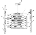
また、この盗難防止装置本体1は、図2に示すように、ケース1aから複数本のリード線1bが延長され、図1に示すように、車両側のバッテリー電源7、メインスイッチ8及びエンジンの点火回路9と、インジケータランプ5と、サイレン4と、一対のセンサ2,3とが接続されると共に、リモコン6からの指令信号が受信されるようになっている。これらリード線1bは、図示していないが、一本毎にゴム質のグロメットに挿通され、このグロメットがケース1aに嵌合されてシールされるようになっている。さらに、そのケース1aには図示していないが、一部に開口が設けられ、この開口を閉塞するように、水は通過しないが空気は通過する膜を設けて呼吸できるように構成されている。
【0013】
ちなみに、防水の為、樹脂で盗難防止装置本体1をモールドする方法も考えられるが、電波の受信回路の部分をモールドしてしまうと浮遊容量が変化してしまい、受信できなくなってしまう。
【0014】
さらに、乗車中重要である点火回路9の制御部分に、振動に強いFETを採用し、イグナイタ点火カットの制御をFETにて行う。
【0015】
リレーを用いると振動によるチャタリングが発生し、最悪の場合、エンジンが停止してしまう虞があるが、FETを用いることにより、これを防止できる。
【0016】
さらにまた、前記リモコン6は、図3に示すように、リモコン本体6aに、システムをセット、解除、或いはサイレン4を止める為の第1押しボタン6bと、サイレン4を止めたり、システムの自動セットを不作動とする第2押しボタン6cとが設けられると共に、電池の状態を表示するLEDランプ6dが設けられている。
【0017】
そのリモコン本体6aの前記ボタン6b,6cが配設された配設面部6eには、第1押しボタン6bの配設部分に凹所6fが形成され、この凹所6fにより、段差形状に形成され、この段差による高さの異なる配設面部6eに各押しボタン6b,6cが配置されている。
【0018】
また、サイレン4は、盗難防止装置本体1の制御により、警報音を所定時間発生するようになっている。この発生時間は、初期状態では15秒に設定されているが、3〜60秒までの任意の時間に変更することが出来るようになっている(詳細は後述する)。
【0019】
さらに、センサ2は、車両の左右方向の傾きを検出するようになっており、又、センサ3は、車両の前後方向の傾きを検出するようになっている。
【0020】
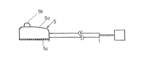
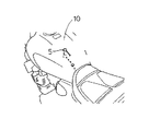
さらにまた、インジケータランプ5は、点灯、点滅により、システムのセット、解除などの状態を表示するように構成されており、図4に示すように、インジケータランプ本体5aの図中上面部に発光部5bが設けられ、底面には、両面テープ5cが設けられている。そして、インジケータランプ5は、図5に示すように、両面テープ5cにより、燃料タンク10の上面に貼り付けられている。
【0021】
このインジケータランプ5の表示と、システムの作動状態とは、図6に示すように盗難防止装置本体1により制御されるようになっている。
【0022】
そして、この盗難防止装置には、以下のような機能が設けられている。
【0023】
(1)基本機能
▲1▼アラーム機能
車両の姿勢変化をセンサ2,3が検知したときや、メインスイッチ8の不正操作(システムの解除を伴わない操作)などがあったときに警報音を発生する。
【0024】
これにより、車両を揺らしたり、移動するなどのいたずらに対し警報するようにしている。
【0025】
▲2▼イモビライザー機能
システムがセットされると、エンジンの点火回路9を遮断し、エンジンが作動できないようにする。
【0026】
これにより、リモコンによる解除操作を行わない限り、メインスイッチ8の不正操作、配線直結などを行ってもエンジンが始動できないこととなる。
【0027】
▲3▼作動表示機能
システムの作動状態をインジケーターランプ5で上述のように表示する。
【0028】
これにより、システムが作動中であることを表示し、車両に対するいたずらを抑止する。
【0029】
(2)その他の機能
▲1▼サイレン作動時間の変更
メインスイッチ8の操作によりサイレン作動時間を設定する(詳細は後述する)。
【0030】
これにより、サイレン作動時間を3〜60秒までの任意の時間に設定できる。
【0031】
▲2▼スリープ機能
システムを24時間以上継続使用したときに消費電流を低減する。図7に示すように、システム作動開始から24時間以内では、アラーム機能、イモビライザー機能、リモコン操作、インジケータランプ表示が可能であるが、24時間経過すると、スリープ状態となり、アラーム機能及びイモビライザー機能は作動可能であるが、リモコン操作及びインジケータランプの表示はできない。
【0032】
これにより、システムを長時間使用する場合、自動二輪車のバッテリーの負担を軽減する。
【0033】
次に、盗難防止装置本体1の構成等を作用と共に説明する。
【0034】
(1)システムをセットする。
【0035】
自動二輪車のメインスイッチ8をOFFすることにより、システムは自動的にセットされる。また、リモコン6による手動セットも可能である。
【0036】
▲1▼自動セット
図8に示すように、自動二輪車のメインスイッチ8をOFFにすると、盗難防止装置本体1の自動セット手段12により、インジケータランプ5が60秒間点灯される。これが準備状態であり、その後、インジケータランプ5が約2秒に1回、点滅する。これで、システムがセット状態となる。
【0037】
▲2▼リモコン6によるセット
図9に示すように、メインスイッチ8をOFFにした後、リモコン6の第1押しボタン6bを押すと、盗難防止装置本体1により、インジケータランプ5が2秒間に4回点滅した後、2秒間に1回の点滅に変わる。これで、システムがセット状態となる。この場合には、自動セットの場合と異なり、60秒間待たずにセットが可能となる。
【0038】
(2)システムを解除する。
【0039】
自動二輪車のメインスイッチ8をOFFにすると、システムは自動的にセットされているため、自動二輪車に乗る前に解除する必要がある。
【0040】
システム解除は、以下のようにして行う(図10参照)。
【0041】
リモコン6の第1押しボタン6bを押すと、盗難防止装置本体1により、インジケータランプ5の点滅が点灯に変わる。なお、システムが作動中にサイレン4が鳴った経歴がある場合には点滅から点灯に変わる前に2回点滅する。
【0042】
そして、自動二輪車のメインスイッチ8をONにすると、インジケータランプ5が消灯する。この状態で、エンジンをかけることが出来る。
【0043】
(3)システムを自動セット不能とする。
【0044】
ガソリンスタンドで給油する場合や自動二輪車を整備する場合など、システムを自動的にセットさせたくない場合がある。
【0045】
そのような場合に、以下の操作をすることにより、自動セットされないようにすることが出来る(図11参照)。
【0046】
▲1▼ メインスイッチ8がONの状態で、リモコン6の第2押しボタン6cを押すと、このリモコン6から自動セット不作動指令信号が盗難防止装置本体1のリモコン受信手段13に受信され、このリモコン受信手段13からの信号が制御手段11に入力され、この制御手段11により、前記自動セット手段12が不作動とされ、インジケーターランプ5が2回点滅した後消灯する。この状態で、メインスイッチ8をOFFにしてもアラーム(システム)の自動セットが不能となる。
【0047】
これにより、ガソリンを給油するときなどに、サイレン4が不用意に鳴るようなことがない。
【0048】
(4)スリープ機能の解除
スリープ機能が働いている間は、上述のように、リモコン6によるシステムの解除が出来ないが、アラーム機能やイモビライザー機能は作動中であるため、乗車する前に以下の操作で、システムを解除する(図12参照)。
【0049】
▲1▼リモコン受信手段13を構成する受信回路への電源供給をON/OFFするスイッチ回路14が設けられており、このスイッチ回路14によりOFF状態に設定されている状態、つまり、スリープ機能が働いている状態から、メインスイッチ8をONすると、スイッチ回路14によりリモコン受信手段13を構成する受信回路への電源供給がOFF状態からON状態へ移行し、インジケーターランプが2秒に1回点滅する。これにより、スリープ機能が解除され、システムがセット状態となると共に、この場合、システムの解除を伴わないメインスイッチ8の操作であるが、サイレン4が鳴らないように制御手段11により制御される。
【0050】
このようにすれば、スリープ機能により、消費電力を削減できると共に、メインスイッチ8をONすることによりスリープ機能を解除しても不用意にサイレン4が鳴るようなことがない。
【0051】
その後、リモコン6の第1押しボタン6b又は第2押しボタン6cを押すと、インジケーターランプ5が消灯する。これにより、システムのセット状態が解除され、この状態で、エンジンをかけることが出来る。
【0052】
(5)サイレン4を止める。
【0053】
リモコン6の第1押しボタン6b、又は第2押しボタン6cを押すことにより、サイレン4を止めることが出来る。第1押しボタン6bを押した場合には、サイレン4が止まった後、システムが解除され、1分後に再セットされることとなる。
【0054】
(6)サイレン4の作動時間を変更する。
【0055】
サイレン4の作動時間、つまり、サイレン4から警報が発生している時間は、盗難防止装置本体1の警報発生時間設定手段16により設定されており、ここでは、例えば初期状態で15秒に設定されているが、以下の操作を行うことにより、変更することが出来る。このサイレン4の作動時間(警報発生時間)は、3〜60秒までの任意の時間に設定することが出来る。
【0056】
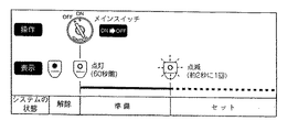
▲1▼図13に示すように、メインスイッチ8をOFFにする。
【0057】
▲2▼バッテリ電源に接続されているコネクタを一旦外して、再度接続する。これにより、バッテリ電源が投入されたことが盗難防止装置本体1の電源投入検知手段15により検知されると共に、インジケータランプ5が点灯する。
【0058】
▲3▼メインスイッチ8をONにすると、サイレン4が鳴り、設定したい時間が経過したら、メインスイッチ8をOFFにする。すると、サイレン4が止まる。
【0059】
これにより、電源投入検知手段15からの信号により、バッテリー電源7が投入されたことを検知した後、メインスイッチ8がONされた時からOFFされるまでの時間を時間検出手段17にて検出して、前記警報発生時間設定手段16の設定時間を当該検出時間に制御手段11にて書き換える。
【0060】
従って、このメインスイッチ8ONにしてからOFFにするまでの間(サイレン4が鳴っている時間)が設定時間となる。
【0061】
なお、設定し直す場合には、上記操作を再度行うことにより、設定できる。
【0062】
このように、コネクタを断・接操作し、メインスイッチ8をON・OFFすることにより、設定時間を変更できるため、盗難防止装置本体1につまみ或いは電源ON/OFFスイッチ等を設ける必要がなく、防水構造を施す必要がない。
【0063】
一方、そのリモコン本体6aの各ボタン6b,6cは、段差による高さの異なる配設面部6eに配置されているため、触覚的に何れのボタン6b,6cであるか判断でき、操作性が良好である。また、そのボタン6b,6cは、比較的大型で押し易いと共に、リモコン本体6aの角部は丸みを帯びており、手になじみ易い。
【0064】
また、インジケータランプ5は、略水平面である燃料タンク10の上面に両面テープ5cにより貼り付けるようにしているため、車体側にステイ等を配設する必要なく、部品点数を削減できると共に、配設作業性を向上させることができる。また、貼付け場所はハンドルクラウン上面、メーター周囲で、他のインジケータ近傍等でも良い。
【0065】
【発明の効果】
以上説明してきたように、請求項に記載された発明によれば、メインスイッチの操作により、警報音の発生時間を変更できるため、盗難防止装置本体に時間変更用のつまみを設ける必要なく、防水構造を施す必要がない。また、リモコンを有する場合でも、設定変更に際しては、これを用いないので、ボタン数の増加等を招かず操作性の悪化を伴わない、という実用上有益な効果を発揮する。
【図面の簡単な説明】
【図1】この発明の実施の形態に係る車両用盗難防止装置のブロック図である。
【図2】同実施の形態に係る盗難防止装置の分解斜視図である。
【図3】同実施の形態に係る盗難防止装置のリモコンを示す図で、(a)は正面図、(b)は平面図、(c)は底面図、(d)は右側面図である。
【図4】同実施の形態に係るインジケーターランプの正面図である。
【図5】同実施の形態に係るインジケーターランプの配設状態を示す斜視図である。
【図6】同実施の形態に係る作動状態とインジケーターランプの表示との関係を示す図である。
【図7】同実施の形態に係るスリープ時の機能が制限される状態を示す図である。
【図8】同実施の形態に係るシステムの自動セットを説明するための図である。
【図9】同実施の形態に係るシステムのリモコンによるセットの状態を示す図である。
【図10】同実施の形態に係るシステムを解除する場合の説明図である。
【図11】同実施の形態に係るシステムの自動セットを不作動とする場合の説明図である。
【図12】同実施の形態に係るスリープ機能を解除する場合の説明図である。
【図13】同実施の形態に係るサイレン作動時間を変更する場合の説明図である。
【符号の説明】
1 盗難防止装置本体
2,3 センサ(車体姿勢変化検出手段)
4 サイレン(警報発生手段)
5 インジケーターランプ
5a インジケーターランプ本体
5b 発光部
5c 両面テープ
6 リモコン
6a リモコン本体
6b 第1押しボタン
6c 第2押しボタン
6e 配設面部
7 バッテリー電源
8 メインスイッチ
10 燃料タンク
11 制御手段
12 自動セット手段
13 リモコン受信手段
14 スイッチ回路
15 電源投入検知手段
16 警報発生時間設定手段
17 時間検出手段[0001]
BACKGROUND OF THE INVENTION
The present invention relates to a vehicle antitheft device, and more particularly to an antitheft device capable of changing the generation time of an alarm sound.
[0002]
[Prior art]
Conventionally, in order to prevent theft of a motorcycle, there is one configured to detect a change in the posture of a vehicle body while parked and issue an alarm (for example, Japanese Patent Laid-Open Nos. 6-31647 and 6-305397). (See publications).
[0003]
[Problems to be solved by the invention]
However, in such a conventional device, it may be possible to change the time during which the alarm sound is generated by providing a knob on the anti-theft device body and operating this knob. If the anti-theft device body is provided, a waterproof structure is required, and the structure becomes complicated.
[0004]
Also, if you have a remote control for each operation, you can change the setting with this remote control, but it will increase the number of buttons, etc., especially when operating the remote control through gloves worn when riding a motorcycle Operability is deteriorated.
[0005]
Therefore, the present invention provides a vehicle antitheft device that can change the alarm sound generation time without providing a waterproof structure or the like to the antitheft device main body, and without deteriorating its operability even when it has a remote control. It is an issue to provide.
[0006]
[Means for Solving the Problems]
In order to achieve such an object, the invention described in
[0008]
DETAILED DESCRIPTION OF THE INVENTION
Embodiments of the present invention will be described below.
[0009]
1 to 13 show an embodiment of the present invention.
[0010]
First, the structure will be described. The anti-theft device of this embodiment includes an
[0011]
The
[0012]
Further, as shown in FIG. 2, the
[0013]
Incidentally, a method of molding the anti-theft device
[0014]
Further, an FET resistant to vibration is adopted as a control part of the ignition circuit 9 which is important during riding, and the igniter ignition cut is controlled by the FET.
[0015]
When a relay is used, chattering due to vibration occurs, and in the worst case, the engine may stop, but this can be prevented by using an FET.
[0016]
Further, as shown in FIG. 3, the
[0017]
A
[0018]
Further, the siren 4 generates an alarm sound for a predetermined time under the control of the
[0019]
Further, the
[0020]
Furthermore, the
[0021]
The display of the
[0022]
The anti-theft device has the following functions.
[0023]
(1) Basic function (1) Alarm function Generates an audible alarm when
[0024]
As a result, a warning is given for mischief such as shaking or moving the vehicle.
[0025]
(2) When the immobilizer function system is set, the engine ignition circuit 9 is shut off so that the engine cannot be operated.
[0026]
As a result, unless the release operation is performed by the remote controller, the engine cannot be started even if the main switch 8 is illegally operated or the wiring is directly connected.
[0027]
(3) Operation display function The operation state of the system is displayed by the
[0028]
As a result, it is displayed that the system is operating, and mischief with respect to the vehicle is suppressed.
[0029]
(2) Other functions (1) Change of siren operating time The siren operating time is set by operating the main switch 8 (details will be described later).
[0030]
Thereby, the siren operation time can be set to any time from 3 to 60 seconds.
[0031]
(2) Reduce current consumption when the sleep function system is used continuously for more than 24 hours. As shown in Fig. 7, the alarm function, immobilizer function, remote control operation and indicator lamp display are possible within 24 hours from the start of system operation, but after 24 hours, the sleep function is entered and the alarm function and immobilizer function are activated. Although it is possible, remote control operation and indicator lamp display are not possible.
[0032]
This reduces the burden on the motorcycle battery when the system is used for a long time.
[0033]
Next, the configuration and the like of the anti-theft device
[0034]
(1) Set the system.
[0035]
The system is automatically set by turning off the main switch 8 of the motorcycle. Manual setting by the
[0036]
(1) Automatic setting As shown in FIG. 8, when the main switch 8 of the motorcycle is turned off, the
[0037]
(2) Set by
[0038]
(2) Cancel the system.
[0039]
When the main switch 8 of the motorcycle is turned off, the system is automatically set, so it is necessary to release it before getting on the motorcycle.
[0040]
The system is released as follows (see FIG. 10).
[0041]
When the
[0042]
When the main switch 8 of the motorcycle is turned on, the
[0043]
(3) Disable automatic system setting.
[0044]
There are cases where you do not want to set the system automatically, such as when refueling at a gas station or when servicing a motorcycle.
[0045]
In such a case, it is possible to prevent automatic setting by performing the following operation (see FIG. 11).
[0046]
(1) When the
[0047]
As a result, the siren 4 does not ring carelessly when refueling.
[0048]
(4) Canceling the sleep function While the sleep function is working, the
[0049]
(1) A
[0050]
In this way, power consumption can be reduced by the sleep function, and even if the sleep function is canceled by turning on the main switch 8, the siren 4 is not inadvertently sounded.
[0051]
Thereafter, when the
[0052]
(5) Stop the siren 4.
[0053]
By pressing the
[0054]
(6) Change the operation time of the siren 4.
[0055]
The operation time of the siren 4, that is, the time during which an alarm is generated from the siren 4 is set by the alarm generation time setting means 16 of the
[0056]
(1) As shown in FIG. 13, the main switch 8 is turned off.
[0057]
(2) Disconnect the connector connected to the battery power supply and connect it again. Thereby, the power-on detection means 15 of the
[0058]
(3) When the main switch 8 is turned on, the siren 4 sounds, and when the time to be set has elapsed, the main switch 8 is turned off. Then, the siren 4 stops.
[0059]
Thus, the time detection means 17 detects the time from when the main switch 8 is turned on to when it is turned off after detecting that the battery power supply 7 is turned on by a signal from the power-on detection means 15. Then, the
[0060]
Therefore, the time from when the main switch 8 is turned on to when it is turned off (the time during which the siren 4 is ringing) is the set time.
[0061]
In addition, when resetting, it can set by performing the said operation again.
[0062]
In this way, the setting time can be changed by turning on / off the connector and turning on / off the main switch 8, so there is no need to provide a knob or a power ON / OFF switch on the
[0063]
On the other hand, since the
[0064]
Further, since the
[0065]
【The invention's effect】
As described above, according to the invention described in the claims, since the alarm sound generation time can be changed by operating the main switch, it is not necessary to provide a time change knob on the anti-theft device main body, There is no need to apply structure. Even in the case of having a remote control, since this is not used when changing the setting, a practically beneficial effect of not causing an increase in the number of buttons or the like and not deteriorating operability is exhibited.
[Brief description of the drawings]
FIG. 1 is a block diagram of a vehicle antitheft device according to an embodiment of the present invention.
FIG. 2 is an exploded perspective view of the anti-theft device according to the embodiment.
3A and 3B are diagrams showing a remote controller of the antitheft device according to the embodiment, where FIG. 3A is a front view, FIG. 3B is a plan view, FIG. 3C is a bottom view, and FIG. .
FIG. 4 is a front view of the indicator lamp according to the embodiment.
FIG. 5 is a perspective view showing an arrangement state of the indicator lamp according to the embodiment.
FIG. 6 is a diagram showing a relationship between an operating state and display of an indicator lamp according to the embodiment.
FIG. 7 is a diagram showing a state where functions at the time of sleep according to the embodiment are restricted;
FIG. 8 is a diagram for explaining automatic setting of the system according to the embodiment;
FIG. 9 is a diagram showing a set state by the remote controller of the system according to the embodiment;
FIG. 10 is an explanatory diagram for releasing the system according to the embodiment;
FIG. 11 is an explanatory diagram when the automatic setting of the system according to the embodiment is deactivated;
FIG. 12 is an explanatory diagram for canceling a sleep function according to the embodiment;
FIG. 13 is an explanatory diagram when changing the siren operating time according to the embodiment;
[Explanation of symbols]
1
4 Siren (alarm generating means)
5 Indicator lamp
5a Indicator lamp body
5b Light emitter
5c Double-
6a Remote control unit
6b First push button
6c Second push button
6e Arrangement surface 7 Battery power supply 8 Main switch
10 Fuel tank
11 Control means
12 Automatic setting means
13 Remote control receiving means
14 Switch circuit
15 Power-on detection means
16 Alarm generation time setting method
17 Time detection means
Claims (1)
Priority Applications (1)
| Application Number | Priority Date | Filing Date | Title |
|---|---|---|---|
| JP16288398A JP4144936B2 (en) | 1998-05-27 | 1998-05-27 | Vehicle antitheft device |
Applications Claiming Priority (1)
| Application Number | Priority Date | Filing Date | Title |
|---|---|---|---|
| JP16288398A JP4144936B2 (en) | 1998-05-27 | 1998-05-27 | Vehicle antitheft device |
Publications (2)
| Publication Number | Publication Date |
|---|---|
| JPH11334664A JPH11334664A (en) | 1999-12-07 |
| JP4144936B2 true JP4144936B2 (en) | 2008-09-03 |
Family
ID=15763084
Family Applications (1)
| Application Number | Title | Priority Date | Filing Date |
|---|---|---|---|
| JP16288398A Expired - Lifetime JP4144936B2 (en) | 1998-05-27 | 1998-05-27 | Vehicle antitheft device |
Country Status (1)
| Country | Link |
|---|---|
| JP (1) | JP4144936B2 (en) |
Families Citing this family (2)
| Publication number | Priority date | Publication date | Assignee | Title |
|---|---|---|---|---|
| US6268794B1 (en) * | 2000-01-21 | 2001-07-31 | Harley-Davidson Motor Company Group, Inc. | Integrated security, tip-over, and turn signal system |
| JP3988926B2 (en) | 2002-07-31 | 2007-10-10 | ヤマハ発動機株式会社 | Apparatus for detecting tire pressure and other conditions in a motorcycle |
-
1998
- 1998-05-27 JP JP16288398A patent/JP4144936B2/en not_active Expired - Lifetime
Also Published As
| Publication number | Publication date |
|---|---|
| JPH11334664A (en) | 1999-12-07 |
Similar Documents
| Publication | Publication Date | Title |
|---|---|---|
| JP2007084948A (en) | Wearing-type air bag device | |
| JP2001247067A (en) | System integrated with security, tipover and direction indicating signal | |
| US5705976A (en) | Antitheft alarm system for a car and a car stereo having a removable panel | |
| WO2015107485A1 (en) | Child protection system and apparatus | |
| JP4144937B2 (en) | Vehicle antitheft device | |
| JP4154032B2 (en) | Vehicle antitheft device | |
| JP4144936B2 (en) | Vehicle antitheft device | |
| JP3001514B2 (en) | Vehicle safety device | |
| ITRM20000701A1 (en) | TOASTED SOYBEAN FOOD PRODUCT SUITABLE TO PREPARE A HOT DRINK AND ITS PROCEDURE OF OBTAINING. | |
| JP3668388B2 (en) | Vehicle antitheft device | |
| JP2645291B2 (en) | Motorcycle ignition control device | |
| US7095332B2 (en) | Alarm device | |
| JP2004086680A (en) | Burglar alarm of on-vehicle electronic equipment | |
| JP2610850B2 (en) | Vehicle power input device | |
| US20110156892A1 (en) | On-board equipment and control method thereof | |
| KR0117126Y1 (en) | Equipment of preventing sleeping of driver | |
| JP2000016363A (en) | Bicycle lamp having burglar alarm | |
| JP2007112405A (en) | Anti-theft device for vehicle | |
| JP3780890B2 (en) | Car burglar alarm device | |
| JP7083286B2 (en) | Work vehicle | |
| CN206752340U (en) | A kind of parking stall alarming device | |
| KR100534320B1 (en) | Device for preventing the theft of car using the clock equipped with instrument panel | |
| JPH0542929Y2 (en) | ||
| JP2584707Y2 (en) | Car stereo | |
| JPH10273016A (en) | Device to prevent window from being left open |
Legal Events
| Date | Code | Title | Description |
|---|---|---|---|
| A621 | Written request for application examination |
Free format text: JAPANESE INTERMEDIATE CODE: A621 Effective date: 20050203 |
|
| A977 | Report on retrieval |
Free format text: JAPANESE INTERMEDIATE CODE: A971007 Effective date: 20070830 |
|
| A131 | Notification of reasons for refusal |
Free format text: JAPANESE INTERMEDIATE CODE: A131 Effective date: 20070904 |
|
| A521 | Written amendment |
Free format text: JAPANESE INTERMEDIATE CODE: A523 Effective date: 20071105 |
|
| TRDD | Decision of grant or rejection written | ||
| A01 | Written decision to grant a patent or to grant a registration (utility model) |
Free format text: JAPANESE INTERMEDIATE CODE: A01 Effective date: 20080520 |
|
| A01 | Written decision to grant a patent or to grant a registration (utility model) |
Free format text: JAPANESE INTERMEDIATE CODE: A01 |
|
| A61 | First payment of annual fees (during grant procedure) |
Free format text: JAPANESE INTERMEDIATE CODE: A61 Effective date: 20080617 |
|
| R150 | Certificate of patent or registration of utility model |
Free format text: JAPANESE INTERMEDIATE CODE: R150 |
|
| FPAY | Renewal fee payment (event date is renewal date of database) |
Free format text: PAYMENT UNTIL: 20110627 Year of fee payment: 3 |
|
| FPAY | Renewal fee payment (event date is renewal date of database) |
Free format text: PAYMENT UNTIL: 20120627 Year of fee payment: 4 |
|
| FPAY | Renewal fee payment (event date is renewal date of database) |
Free format text: PAYMENT UNTIL: 20130627 Year of fee payment: 5 |
|
| R250 | Receipt of annual fees |
Free format text: JAPANESE INTERMEDIATE CODE: R250 |
|
| R250 | Receipt of annual fees |
Free format text: JAPANESE INTERMEDIATE CODE: R250 |
|
| R250 | Receipt of annual fees |
Free format text: JAPANESE INTERMEDIATE CODE: R250 |
|
| R250 | Receipt of annual fees |
Free format text: JAPANESE INTERMEDIATE CODE: R250 |
|
| R250 | Receipt of annual fees |
Free format text: JAPANESE INTERMEDIATE CODE: R250 |
|
| EXPY | Cancellation because of completion of term |