JP4144929B2 - Mobile transformer equipment - Google Patents
Mobile transformer equipment Download PDFInfo
- Publication number
- JP4144929B2 JP4144929B2 JP08648598A JP8648598A JP4144929B2 JP 4144929 B2 JP4144929 B2 JP 4144929B2 JP 08648598 A JP08648598 A JP 08648598A JP 8648598 A JP8648598 A JP 8648598A JP 4144929 B2 JP4144929 B2 JP 4144929B2
- Authority
- JP
- Japan
- Prior art keywords
- voltage
- circuit breaker
- low
- side wall
- transformer
- Prior art date
- Legal status (The legal status is an assumption and is not a legal conclusion. Google has not performed a legal analysis and makes no representation as to the accuracy of the status listed.)
- Expired - Lifetime
Links
Images


Landscapes
- Housings And Mounting Of Transformers (AREA)
- Stand-By Power Supply Arrangements (AREA)
Description
【0001】
【発明の属する技術分野】
本発明は、既設変圧器の無停電交換工事や災害時等に使用される移動変圧器設備に関するものである。
【0002】
【従来の技術】
既設変圧器を無停電で交換する場合や、災害等で既設変圧器が使用できなくなった場合には、トラック等の移動用車両に搭載されて工事現場や災害現場に運ばれる移動変圧器設備が用いられる。従来の移動変圧器設備は、手動で操作されるタップ切換器を備えた移動変圧器と、既設変圧器の一次側の各線に高圧側ケーブルを介してそれぞれ接続される高圧側端子と、この高圧側端子と移動変圧器の一次側端子との間に配置された高圧側遮断器と、既設変圧器の二次側の各線に低圧側ケーブルを介してそれぞれ接続される低圧側端子と、この低圧側端子と移動変圧器の二次側端子との間に配置された低圧側遮断器と、低圧側遮断器の投入条件を判定して少なくとも低圧遮断器の投入を制御する制御装置とが、専用のトラックの荷台上に構築された大型の収納ケースの内部に収納された構造を有している。また収納ケースには、高圧側ケーブル及び低圧側ケーブルを収納するケーブル収納室も設けられている。
【0003】
【発明が解決しとする課題】
しかしながら従来は、専用のトラックの荷台上に大型の収納ケースを構築するという発想の下に移動変圧器設備を構成していたので、特に設備をコンパクト化する必要がなかった。そのため収納ケースの内部に収納する各機器の配置に関してもコンパクト化のための格別な工夫がなされていないのが現状であった。
【0004】
本発明の目的は、専用のトラックを用意するのではなく、一般的なトラックで搬送可能な小型の移動変圧器設備を提供することにある。
【0005】
本発明の他の目的は、小型でしかも組み立ての容易な移動変圧器設備を提供することにある。
【0006】
本発明の他の目的は、小型でしかも操作の安全性に優れた移動変圧器設備を提供することにある。
【0007】
本発明の更に他の目的は、小型化してしかも高圧側ケーブル及び低圧側ケーブルを併せて搬送できる移動変圧器設備を提供することにある。
【0008】
【課題を解決するための手段】
本発明が改良の対象とする移動変圧器設備は、手動で操作されるタップ切換器を備えた移動変圧器と、既設変圧器の一次側(高圧側)の各線に高圧側ケーブルを介してそれぞれ接続される高圧側端子と、高圧側端子と移動変圧器の一次側端子との間に配置された高圧側遮断器と、既設変圧器の二次側(低圧側)の各線に低圧側ケーブルを介してそれぞれ接続される低圧側端子と、低圧側端子と移動変圧器の二次側端子との間に配置された低圧側遮断器と、低圧側遮断器の投入条件を判定して少なくとも低圧側遮断器の投入を制御する制御装置とを具備している。そして少なくとも移動変圧器、高圧側遮断器、低圧側遮断器及び制御装置が移動可能な収納ケースに収納されている。なお高圧側端子及び低圧側端子は収納ケースの内部または外部に配置することができる。
【0009】
本発明においては、移動変圧器を、第1の側面にタップ切換器の手動操作部を有し、第1の側面と対向する第2の側面に一次側端子を備え、第1の側面と第2の側面との間に位置する第3の側面に二次側端子を備えた構造とする。また収納ケースは、第1の開口部を有する第1の側壁部と、第2の開口部を有して第1の側壁部と対向する第2の側壁部と、第1及び第2の側壁部の間に位置する第3の側壁部と、第3の側壁部と対向する第4の側壁部とを備えた構造とする。なお第3の側壁部には第3の開口部を設けてもよい。更に収納ケースの第1乃至第3の開口部に対しては、それぞれ開閉扉を設ける。
【0010】
そして移動変圧器は、第1の側面が第1の側壁部と対向し、第2の側面が第2の側壁部と対向し、第3の側面が前記第3の側壁部と対向するように収納ケースの内部に配置する。また収納ケースの内部には第1の側壁部の第1の開口部を通して操作可能な位置に制御装置の操作部と低圧側遮断器とを配置する。更に収納ケースの内部の第2の側壁部と移動変圧器の第2の側面との間の空間内に高圧側遮断器を配置する。そして更に収納ケースの内部には第3の側壁部の第3の開口部を通して接続可能な位置に高圧側端子と低圧側端子が配置し、第3の開口部内において、高圧側端子を収納ケースの第2の側壁部側に配置し、また低圧側端子を第1の側壁部側に配置する。第3の開口部を設けない場合には、第3の側壁部の外側に高圧側端子及び低圧側端子を設ければよく、その場合にも高圧側端子を収納ケースの第2の側壁部側に配置し、また低圧側端子を第1の側壁部側に配置する。
【0011】
本発明のように、移動変圧器の第1の側面側にタップ切換器の手動操作部と、制御装置の操作部と低圧側遮断器を配置して、収納ケースの第1の開口部からタップ切換器の手動操作部と制御装置の操作部とを操作できるようにし、また移動変圧器の第1の側面と反対側の第2の側面側に高圧側遮断器を配置して収納ケースに設けた第2の開口部を通して高圧側遮断器にアクセスできるようにし、更に収納ケースの第3の側壁部に設けた第3の開口部を通して接続可能な位置に配置した高圧側端子及び低圧側端子を(または第3の側壁部の外側に配置した高圧川端子及び低圧側端子を)、高圧側端子は収納ケースの第2の側壁部側に配置し、低圧側端子は第1の側壁部側に配置することにより、移動変圧器の両側に低圧側機器と高圧側機器とを別けて配置することができて、収納ケースの第3の側壁部と第4の側壁部との間の距離を短くしても、各機器を収納ケースの内部に収納することができる。したがって収納ケースを従来よりも大幅に小型化することができる。また収納ケースの内部における低圧側の電気的な接続と高圧側の電気的な接続とを、短い配線で且つ配線が複雑にならずに、簡単に行うことができる。また低圧側遮断器と高圧側遮断器とを移動変圧器の両側に別けて配置すると、手動操作により低圧側遮断器と高圧側遮断器とを操作する場合に、低圧側と高圧側を誤って操作する可能性が低くなる。
【0012】
特に、移動変圧器の第2の側面に、高圧側遮断器と高圧側端子との間に設けられる限流ヒューズを固定し、高圧側遮断器を限流ヒューズの下方に配置すると、限流ヒューズを固定するための構造物が不要になるだけでなく、限流ヒューズと高圧側遮断器の設置スペースを小さくすることができて、収納ケースの更なる小型化を図ることができる。
【0013】
また移動変圧器の第3の側面に、低圧側遮断器を固定すると、低圧側遮断器を固定するための構造物が不要になるだけでなく、低圧側遮断器の設置スペースを小さくすることができる。
【0014】
更に移動変圧器の第3の側面に、移動変圧器の二次側端子と低圧側遮断器とを接続するケーブルに装着されて電流を測定する変流器を固定すると、変流器を固定するためだけの構造物が不要になるだけでなく、変流器の設置スペースを小さくすることができる。
【0015】
収納ケースの上部に、高圧側ケーブル及び低圧側ケーブルを収納するケーブル収納部を設けると、収納ケースの高さが若干高くなるだけで、収納ケースの横断面形状を大きくする必要がない。そのため収納ケースが小型化を図ることができる。なおケーブル収納部は、ケーブルを完全に収納する構造を有している必要はなく、少なくとも上方が開口した形状を有しているのが好ましい。
【0016】
【発明の実施の形態】
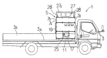
以下図面を参照して本発明の実施の形態の一例を詳細に説明する。図1〜図4は、本発明の移動変圧器設備5をトラック3の荷台に搭載したトラック搭載型移動変圧器設備1の左側面図、平面図、右側面図及び背面図である。このトラック3は市販の2トン積みトラックであり、トラック3の荷台3a上の前方寄り(運転席側寄り)の部分に、移動変圧器設備5が搭載されている。
【0017】
図1〜図3を見ると分かるように、移動変圧器設備5はトラック3の荷台3aの前方側に搭載された状態で荷台3aの後方側に作業スペースを残すことができる大きさに構成されている。そして移動変圧器設備5はトラック3の荷台上に所定の固定具を用いて固定されている。市販のトラックであるため、移動変圧器設備5を使用する際には、荷台3aの側方に回転自在に取付けられた側板3b及び3cを外側に開いて、荷台3aの下側に垂らし状態にする。なお理解を容易にするために、図1,図3及び図4においては、側板3b及び3dを透明なものとして描いてある。
【0018】
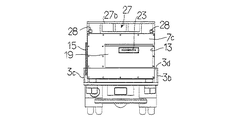
移動変圧器設備5を構成する機器は、すべて収納ケース7の内部に収納されている。収納ケース7は、鉄製のフレーム枠の上に複数枚の鉄板が装着されて構成された箱体構造を有している。収納ケース7は、トラック3の荷台3aの一方の側方側(トラック3を正面から見たときの右側面側)に開口する第1の開口部9を有する第1の側壁部7a(図3参照)と、トラック3の荷台3aの他方の側方側(トラック3を正面から見たときの左側面側)に開口する第2の開口部11を有して第1の側壁部7aと対向する第2の側壁部7b(図1参照)と、第1及び第2の側壁部7a及び7bの間に位置してトラック3の荷台3aの後方側に向かって開口する第3の開口部13を有する第3の側壁部7c(図4参照)と、第3の側壁部7cと対向しトラック3の運転席側に位置する第4の側壁部7d(図1及び図3参照)とを備えている。そして第1乃至第3の開口部9,11,13に対してそれぞれ第1乃至第3の開閉扉15,17,19が設けられている。
【0019】
図3及び図4に示すように第1の開閉扉15及び第3の開閉扉19は、上下方向にスライドするスライド式扉であり、図1に示す第2の開閉扉17は蝶番によって開閉する形式の蝶番式扉である。第1の開口部9の位置は、第1の開閉扉15を上にスライドしたときに第1の開口部9を開き、下にスライドしたときに第1の開口部9が閉じられるように定められている。また第3の開口部13の位置は、第3の開閉扉19を下にスライドしたときに第3の開口部13を開き、上にスライドしたときに第3の開口部13が閉じられるように定められている。なお開閉扉15及び19には、開閉時に掴むハンドル21及び23が設けられている。また第2の開閉扉17にも、扉の開閉時に操作されるレバー25が設けられている。図3には図示していないが、第1の開閉扉15に関しては、スライドの途中で複数段階に別けて扉を停止または固定することができるように、第1の開口部9と第1の開閉扉15の双方に係止構造が設けられている。
【0020】
収納ケース7の天板7eの外周部には4つの柵部材27a〜27dが固定されて、ケーブルを収納するケーブル収納部27が構成されている。また収納ケース7の天板7eの四隅には吊り上げ用の係止金具28が固定されている。
【0021】
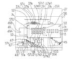
移動変圧器設備5をトラック3の荷台3aの前方側に搭載された状態で荷台3aの後方側に作業スペースを残すことができる大きさに構成するためには、移動変圧器設備5をコンパクト化しなければならない。この例では、次の様にして移動変圧器設備5をコンパクト化した。図5乃至図9は、移動変圧器設備5の収納ケース7の内部の構造を示している。なおこれらの図においては、収納ケースの外枠だけを実線で示してある。またこれらの図においては、理解を容易にするために主要部の配線ケーブルだけを図示してある。またこの装置の回路図は、図10に示してある。
【0022】
これらの図において、29は移動変圧器である。この移動変圧器29は、横長の変圧器ケース31の内部に容量の異なる変圧器コイル(例えば50kW,30kW)が2台横に並ぶように(トラック3の荷台の左右の方向に並ぶように)収納されている。そして収納ケース7の高さをあまり高くしないようにするために、移動変圧器29は収納ケース7の底部を構成するフレームによって形成される孔部に落とし込まれた状態でフレームに固定されている。移動変圧器29は、収納ケース7の第1の側壁部7aと対向する変圧器ケース31の第1の側面31aにタップ切換器の手動操作部(ハンドル)33を有している(図6及び図7参照)。図7に破線で示したように、この手動操作部(ハンドル)33は収納ケース7に設けた第1の開口部9を通して操作可能な位置に設けられている。移動変圧器29の電圧を調整する際に、手動操作部(ハンドル)33は手動によって操作される。
【0023】
図6及び図8に示すように移動変圧器29の変圧器ケース31の第1の側面31aと対向する第2の側面31bには3つの三相の一次側端子(高圧側)35R,35S,35Tが配置されている。また図5及び図8に示すように、変圧器ケース31の第1の側面31aと第2の側面31bとの間に位置する第3の側面31cには、三相の出力端子と中性点端子とを含む4本の二次側端子37U,37V,37W,37Nを備えている。
【0024】
図5,図6及び図8に示すように、収納ケース7の内部には、収納ケース7の第2の側壁部7bと移動変圧器29の変圧器ケース31の第2の側面31bとの間の空間の下側部分内に高圧側遮断器39が配置されている。この高圧側遮断器39については後に詳しく説明する。そして図6及び図8に示すように移動変圧器29の変圧器ケース31の第2の側面31bには、一次側端子35R,35S,35Tの下の位置に、高圧側遮断器39と後に説明する高圧側端子との間に設けられる限流ヒューズ41R,41S,41Tを固定するための支持体43(図8参照)が固定されている。このように限流ヒューズ41R,41S,41Tを変圧器ケース31に固定すると、限流ヒューズ41R,41S,41Tを固定するための特別の構造物が不要になる。また限流ヒューズ41R,41S,41Tの下に高圧側遮断器39を配置すると設置スペースを小さくすることができて、収納ケース7の更なる小型化を図ることができる。
【0025】
高圧側遮断器39は、電動で投入と遮断とを行うことができ、しかも投入後は電力の供給がなくても投入状態を維持できるラッチ機構付の電動式高圧遮断器または高圧電磁接触器である。この種の電動式高圧遮断器としては、例えば株式会社安川電機がロータリアーク高圧電磁接触器HGR−951C−Cの製品名で販売するものを用いることができる。なおこの実施の形態では、図5及び図8に示すように、この市販の高圧電磁接触器の操作軸には手動で高圧側遮断器39の投入を行うための投入レバー45を取付けている。またこの高圧側遮断器39には、ラッチ機構を手動で外すための引き外しレバー46が予め設けられている。投入レバー45及び引き外しレバー46は、図1に示した収納ケース7の第2の側壁部7bに設けた第2の開閉扉17によって塞がれた第2の開口部11を通して操作される。このように第1の開口部9とは別の第2の開口部11を通して投入レバー45及び引き外しレバー46を操作できる位置に高圧側遮断器39を配置すれば、作業員が誤ってこれらのレバー45及び46を操作することを極力防止できる。
【0026】
また図5〜図7に示すように、収納ケース7の内部には、収納ケース7の第1の側壁部7aの第1の開口部9を通して操作可能な位置に制御装置の表示機能付き操作装置47及び手動操作部を含む制御装置固定側本体部48(操作部)と低圧側遮断器49が配置されている。これら表示機能付き操作装置47及び制御装置固定側本体部48は、移動変圧器29の変圧器ケース31の第1の側面31aに固定されている。特に表示機能付き操作装置47は、表示手段と操作指令を高圧側遮断器39及び低圧側遮断器49のそれぞれの駆動回路に出力する操作指令出力手段を含んで持ち運び可能に構成されている。この例では、表示機能付き操作装置47の内部にマイクロコンピュータが内蔵されていて、制御装置で行う判断のすべてをこの内蔵マイクロコンピュータで実行している。また表示機能付き操作装置47の表示手段は、液晶のタッチパネルにより構成されており、表示機能の他にスイッチ機能を備えている。したがって作業者は、表示手段の画面に表示されたスイッチ表示をタッチするだけで、すべての操作指令を入力できる。このような構造になっているため、この例では表示機能付き操作装置47が制御装置の主要部分を構成している。
【0027】
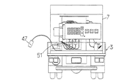
図5に示すように、変圧器ケース31の第1の側面31aには、表示機能付き操作装置47を取り外し自在に固定する操作装置固定部51が設けられている。操作装置固定部51は、表示機能付き操作装置47が操作装置固定部51に固定された状態で収納ケース7の第1の開口部9を通して外部から表示手段を見ることができてしかも表示機能付き操作装置47を操作できる位置に設けられている。表示機能付き操作装置47のケースの両端には、頭部と捩子付の首部を有する係止用捩子部材47cが設けられている。捩子付の首部は表示機能付き操作装置47のケースに捩子結合されている。そして操作装置固定部51を構成する一対の板部材51a,51aには、係止用捩子部材47cの首部が嵌合される溝部51b,51bが形成されている。係止用捩子部材47cの頭部を回して、締め付け力を緩めれば、表示機能付き操作装置47を操作装置固定部51から外すことができる。また表示機能付き操作装置47を操作装置固定部51に取付けた状態で、表示機能付き操作装置47の取付角度を調節することもできる。
【0028】
また制御装置固定側本体部48は、非常時等に高圧側遮断器39を遮断状態にするために高圧側遮断器39の駆動回路に遮断指令信号を出力する非常停止スイッチSW1を含んでいる。そして制御装置固定側本体部48も、収納ケース7の第1の開口部9を通して操作可能な位置に設けられている。表示機能付き操作装置47により高圧側遮断器39及び低圧側遮断器49の両方を操作する場合に、表示機能付き操作装置47に非常停止スイッチを設けて表示機能付き操作装置47側で高圧側遮断器を非常遮断できるようにすると、非常時以外のときに誤って高圧側遮断器39を非常遮断させてしまい、停電事故が発生するおそれがある。そこでこの例では、高圧側遮断器39を電動で遮断するための操作指令を出力する非常停止スイッチSW1を、表示機能付き操作装置47とは別に、制御装置固定側本体部48に設けている。なお制御装置固定側本体部48に設けたスイッチSW2は、制御装置の制御電源スイッチである。
【0029】
図9に示すように、この例では表示機能付き操作装置47は、ケーブルを介して制御装置の制御装置固定側本体部48に接続されている。この例のように制御装置の操作部の一部を構成する表示機能付き操作装置47を持ち運び可能に(可搬に)設けると、トラック3の周囲に十分なスペースがない場合や周囲の見通しが悪い場合に、作業員は表示機能付き操作装置47を持って任意の位置に移動し、任意の位置で高圧側遮断器39及び低圧側遮断器49の操作をすることができる。したがって作業員の負担が大幅に軽減できる。
【0030】
低圧側遮断器49は、移動変圧器29の変圧器ケース31の第3の側面31cに固定された取付フレーム52に固定されている。低圧側遮断器49は、電動で投入と遮断の制御が可能なもので、この例では寺崎電機株式会社がXS400NSの製品名で販売する配線用遮断器を用いている。この低圧側遮断器49は、ケーブル接続端子箱49Aと遮断器本体49Bとにより構成されており、遮断器本体49Bには、故障時の操作を考慮して遮断用の手動操作ハンドルと工具挿入口とが設けられ、また手動投入スイッチも設けられている。低圧側遮断器49は、高圧側遮断器39と異なってラッチ機構を有していないため、故障していない限り、電源がなくなると自動的に遮断する。なお後に説明するように、低圧側遮断器49は、高圧側遮断器39を投入した後に、制御装置(47)により低圧側遮断器49の投入条件の判定が実施されて、制御装置(47)から投入指令が出力されると投入状態になる。
【0031】
収納ケース7の内部には、収納ケース7の第3の側壁部7cに設けた第3の開口部13を通して接続可能な位置にケーブル端子盤53が配置されている。ケーブル端子盤53には、図示しない既設変圧器の一次側の各線に図示しない高圧側ケーブルを介してそれぞれ接続される高圧側端子55R,55S,55Tと、既設変圧器の二次側の各線に図示しない低圧側ケーブルを介してそれぞれ接続される低圧側端子57U1 ,57U2 ,57N1 ,57N2 ,57V1 ,57V2 ,57W1 ,57W2 と、接地端子58とが設けられている。この例では、低圧側端子57U1 〜57W2 を各相について2個ずつ設けている。これは各相について2本ずつのケーブルを用いることにより電流容量を2倍にするためである。なお各相の2つの低圧側端子は、それぞれ収納ケース7の内部で共通の端子部に電気的に接続されている。なお電流容量の大きい高価なケーブルを用いる場合には、低圧側端子を各相について1個ずつ設ければよいのは勿論である。図5に示されるように、高圧側端子55R,55S,55Tは収納ケース7の第2の側壁部7b側に配置され、また低圧側端子57U1 〜57W2 は収納ケース7の第1の側壁部7a側に配置されている。
【0032】
高圧側端子55R,55S,55Tは、図8及び図10に示すように、限流ヒューズ41R〜41Tの高圧側に接続されている。そして限流ヒューズ41R〜41Tの低圧側は高圧側遮断器39の入力端子に接続され、高圧側遮断器39の出力端子は移動変圧器29の一次側端子35R〜35Tに接続されている。また低圧側端子57U1 〜57W2 は、図6,図8及び図10に示すように、低圧側遮断器49のケーブル接続端子箱49Aの出力端子にそれぞれ電気的に接続されている。そして低圧側遮断器49のケーブル接続端子箱49Aの入力端子は、移動変圧器29の二次側端子37U〜37Wにそれぞれ接続されている。図5、図8及び図10に示すように移動変圧器29の二次側端子37U〜37Wと低圧側遮断器49とを接続する4本のケーブルのうち2本のケーブルには移動変圧器29の出力電流を測定するための変流器59及び61が配置されている。これらの変流器59及び61は、移動変圧器29の変圧器ケース31の第3の側面31cに固定した取付板63に固定されている。このようにすると、変流器を固定するためだけの構造物が不要になるだけでなく、変流器の設置スペースを小さくすることができる。
【0033】
この例のように、移動変圧器29の第1の側面31a側にタップ切換器の手動操作部33と、制御装置の操作部(47,48)と低圧側遮断器49を配置して、収納ケース7の第1の開口部9からタップ切換器の手動操作部33と制御装置の操作部(47,48)とを操作できるようにし、また移動変圧器29の第1の側面31aと反対側の第2の側面31b側に高圧側遮断器39を配置して収納ケース7に設けた第2の開口部11を通して高圧側遮断器39にアクセスできるようにし、更に収納ケース7の第3の側壁部7cに設けた第3の開口部13を通して接続可能な位置に配置した高圧側端子55R,55S,55Tを第3の開口部13内において収納ケース7の第2の側壁部7b側に配置し、また低圧側端子57U1 〜57W2 を収納ケース7の第1の側壁部7a側に配置すると、移動変圧器29の両側に低圧側機器と高圧側機器とを別けて配置することができて、収納ケース7の第3の側壁部7cと第4の側壁部7dとの間の距離を短くしても、各機器を収納ケース7の内部に収納することができる。したがって収納ケース7を従来よりも大幅に小型化することができる。またこのように配置すると、収納ケース7の内部における低圧側の電気的な接続と高圧側の電気的な接続とを、短い配線で且つ配線が複雑にならずに、簡単に行うことができる。更に低圧側遮断器49と高圧側遮断器39とを移動変圧器29の両側に別けて配置すると、手動操作により低圧側遮断器49と高圧側遮断器39とを操作する場合に、低圧側と高圧側を誤って操作する可能性が低くなる。
【0034】
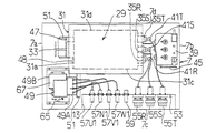
収納ケース7の第1の開口部9を通してアクセスできる位置即ち低圧側遮断器49の下側のスペースには、バッテリ(二次電池)65とバッテリ65の充電器67が配置されている。このバッテリ65は、制御装置(47,48)の電源回路の電源の一部を構成しており、制御装置(47,48)は高圧側遮断器39が投入されるまでは、バッテリ65を電源として動作するように構成されている。このようにバッテリ65を搭載すると、定常運転時の制御電源となる移動変圧器29が充電されていない段階でも、制御装置(47,48)を動作状態にすることができる。そのため高圧側遮断器39を投入する前に低圧側ケーブルの欠相及び接地の不良を検出することができるので、作業の安全性を高めることができる。充電器67の内部には、移動変圧器29の出力を整流してバッテリ65を充電する充電回路が内蔵されており、充電器67は移動変圧器29の運転時にバッテリ65を充電する。また図10を見ると分かるように、バッテリ65は充電端子66を通して100Vの商用電源によっても充電可能である。なお高圧側遮断器39が投入された後は、制御装置(47,48)は充電器67の出力を電源として動作する。そしてこの例では高圧側遮断器39の駆動電力を低圧側遮断器49の出力側即ち既設変圧器の低圧側から得ているが、バッテリ65から高圧側遮断器39の駆動電力を得るようにしてもよいのは勿論である。このようにすると停電時に移動変圧器を使用する場合でも、高圧側遮断器39を電動で駆動することができる。
【0035】
図10に示した回路において、69は高圧側遮断器39の駆動回路であり、71は低圧側遮断器49の駆動回路である。また47aは、表示機能付き操作装置47の内部に収納された制御回路であり、その主要部はマイクロコンピュータによって構成されている。また47bは表示機能付き操作装置47の表示手段であって、この例では液晶タッチパネルにより表示手段47bが構成されている。制御装置の制御回路47aは、移動用変圧器29の二次側出力の電圧U2〜N2と電流を入力として測定した移動用変圧器29の二次側線間電圧及び位相と低圧側端子57U1 〜57W2 を通して入力された既設変圧器の二次側の電圧U1〜N1を測定して得た既設変圧器の二次側の線間電圧及び位相との電圧差及び位相差を検出し、これらの電圧差及び位相差が許容範囲に入っているか否かを判定して、その結果を表示手段47bに表示させる機能(検相機能)を有している。なおこのような検相に関する技術の一例は、実公平5−40681号公報等に詳しく説明されている。
【0036】
また制御回路47aは,電圧U2〜N2及び電圧U1〜N1に基づいて、高圧側ケーブルが高圧側端子55R〜55Tに接続されているか否か及び低圧側ケーブルが低圧側端子57U1 〜57W2 に接続されているか否かを判定して表示手段47bに表示させる機能(誤配線検出機能)を有している。
【0037】
更に制御回路47aには、バッテリ65または充電器67の出力を電源として高圧側遮断器39が投入状態にあるときに投入状態検出信号を出力する高圧側遮断器投入状態検出回路74が接続されている。この高圧側遮断器投入状態検出回路74は、一端がバッテリ65及び充電器67の出力に電気的に接続され他端が制御回路47aの入力に電気的に接続された検出スイッチ73を備えている。この検出スイッチ73は、高圧側遮断器39の操作軸によってオンオフされるマイクロスイッチであり、高圧側遮断器39が投入状態にあるときにオン状態となり、高圧側遮断器39が遮断状態にあるときにオフ状態となる。したがって検出スイッチ73がオン状態にあるときには、制御電源スイッチSW2がオン状態になったときに、制御回路47aにオン信号(投入状態検出信号)が入力され、制御回路47aはこの信号を受信している間表示手段47bに高圧側遮断器39が投入状態にあることを示す表示をする。
【0038】
また制御回路47aには、バッテリ65または充電器67の出力を電源として低圧側遮断器49が投入状態にあるときに投入状態検出信号を出力する低圧側遮断器投入状態検出回路76が接続されている。この低圧側遮断器投入状態検出回路76は、一端がバッテリ65及び充電器67の出力に電気的に接続され他端が制御回路47aの入力に電気的に接続された検出スイッチ75を備えている。この検出スイッチ75は、低圧側遮断器49の操作軸によってオンオフされるマイクロスイッチであり、低圧側遮断器49が投入状態にあるときにオン状態となり、低圧側遮断器49が遮断状態にあるときにオフ状態となる。したがって検出スイッチ75がオン状態にあるときには、制御電源スイッチSW2がオン状態になったときに、制御回路47aにオン信号(投入状態検出信号)が入力され、制御回路47aはこの信号を受信している間表示手段47bに低圧側遮断器49が投入状態にあることを示す表示をする。
【0039】
また制御回路47aは、高圧側遮断器39の投入条件についても判定する機能を有している。この場合の投入条件は、低圧側ケーブルの欠相と接地不良がなく、しかも低圧側遮断器49が遮断状態にあることであり、この投入条件が揃っている場合にのみ、表示手段47bの画面上のスイッチを操作したときに高圧側遮断器39の駆動回路69に投入指令が出力される。この投入条件が揃っていない場合には、表示手段47bに満たされていない投入条件を文字または画像で表示し、また投入条件が満たされている場合にはその旨を表示手段47bに文字または画像で表示するように制御回路47aが構成されている。
【0040】
更に制御回路47aは、低圧側遮断器49の投入条件(検相結果が正しいこと、接地ケーブルを含めてすべてのケーブルが正しく接続されていること、高圧側遮断器39が投入状態にあること)が揃っている場合にのみ低圧側遮断器49の投入を許容する機能(安全機能)を有している。この安全機能は、投入条件が揃っていなければ、表示機能付き操作装置47の表示手段47bの画面上のスイッチを操作しても低圧側遮断器49の駆動回路71に投入指令が出力されないようにする機能である。このような機能は、従来の装置でも採用されている。なおこの例では、表示手段47bに満たされていない投入条件を文字または画像で表示し、また投入条件が満たされている場合には、その旨を表示手段47bに文字または画像で表示するように制御回路47aが構成されている。
【0041】
この例では、高圧側遮断器39の駆動回路69の電源を、低圧側遮断器49の二次側即ち既設変圧器の二次側の電源から(二次側の充電状態にある負荷から)得るようになっており、低圧側遮断器49の駆動回路71の電源は移動変圧器29の二次側から得るようになっている。そのため既設変圧器側が停電状態で低圧側端子57U1 〜57W2 に電圧が印加されていない場合(負荷側が充電状態にない場合)には、高圧側遮断器39を電動では投入状態にすることができない。そのような場合には、手動で投入レバー45を回転させて高圧側遮断器39を投入する。正常時であれば高圧側遮断器39を遮断する場合には、表示機能付き操作装置47により高圧側遮断器39を遮断状態する。そして非常時に高圧側遮断器39を遮断する必要がある場合には、低圧側遮断器49の二次側即ち既設変圧器の二次側が充電状態にあれば、非常停止スイッチSW1をオン状態にして、高圧側遮断器39の駆動回路69の引き外し機構を作動させることにより高圧側遮断器39は遮断状態にする。なお非常時に、低圧側遮断器49の二次側即ち既設変圧器の二次側が充電状態になければ、手動で引き外しレバー46を押し下げることにより高圧側遮断器39のラッチ機構を引き外して高圧側遮断器39を遮断状態にする。
【0042】
この例の装置を例えば既設変圧器を周囲に十分なスペースがない場所で交換する際の作業手順及び装置の運転手順について説明する。トラック3を既設変圧器の近くに停車させる。そして第1及び第3の開閉扉15及び13を開け、第1の開口部9から手を入れて制御装置固定側本体部48上の制御電源スイッチSW2をオン状態にして、バッテリ65により制御回路47aの電源が入る。表示機能付き操作装置47を操作装置固定部51から外し、トラック3の荷台3aの上の作業者に表示機能付き操作装置47を渡す。トラック3の荷台3aの作業者は、収納ケース7の上のケーブル収納部27からケーブルを荷台3aの上に下ろす。そしてトラック3の荷台3aの上の作業者は、表示機能付き操作装置47の表示手段47bの画面で、高圧側遮断器39及び低圧側遮断器49が投入状態にないことを確認した後に、まず荷台3aの上で低圧側端子57U1 〜57W2 に低圧側ケーブルを接続し、接地端子58に接地用ケーブルの一端を接続し、その他端を所定の手順で接地する。次に高圧側端子55R,55S,55Tに高圧側ケーブルを接続する。その後、低圧側ケーブルを既設変圧器の活線状態にある二次側(低圧側)線路に接続する。そしてこの状態で、低圧側ケーブルの欠相及び接地の不良を表示機能付き操作装置47の表示手段47bの画面で確認する。その後、高圧ケーブルを既設変圧器の活線状態にある一次側(高圧側)線路に接続する。
【0043】
次に制御回路47aが高圧側遮断器39の投入条件が揃っていることを表示している場合には、表示機能付き操作装置47の表示手段47a上の高圧側遮断器投入スイッチを押して高圧側遮断器39を投入する。次に低圧側で検相をして制御回路47aが低圧側遮断器49の投入条件を判定し、低圧側遮断器49の投入条件が揃っていることを表示手段47bに表示している場合には、表示機能付き操作装置47の表示手段47a上の低圧側遮断器投入スイッチを押して低圧側遮断器49を投入し、移動変圧器29を既設変圧器と並列運転させる。投入操作は、トラックの荷台3aの上またはトラックの周囲でスペースのある場所に作業者が立って行う。移動変圧器29と既設変圧器の出力電圧が合わない場合には、移動変圧器29のタップ切換器の手動操作部(ハンドル)33を回転させて、電圧調整をする。電圧調整を行っても電圧及び位相が一致しない場合には、ある程度時間をおいて再度投入動作を実行する。移動変圧器29を既設変圧器と並列運転させた後、既設変圧器を配電線から切り離して既設変圧器の交換を行う。そして既設変圧器の交換が完了した後は、交換した変圧器と移動変圧器29を並列運転させた後に、低圧側遮断器49を遮断状態にして切り離し、その後に高圧側遮断器39を遮断状態にする。その後制御電源スイッチSW2をオフ状態とし、また高圧側ケーブルと低圧側ケーブルを取外し、収納ケース7の上のケーブル収納部27にケーブルを載せ、第1及び第3の開閉扉15及び19を閉じる。なお荷台3aの上にはその他の器材及び交換した既設変圧器を載せてもよい。
【0044】
上記例では、収納ケースの外部に極力突出物を出さないようするために、高圧側端子及び低圧側端子を収納ケース7の内部に配置したが、高圧側端子及び低圧側端子を収納ケースの外部または外壁(収納ケースの第3の側壁部)に配置してもよいのは勿論である。
【0045】
また上記例では、第2の開口部を閉じる開閉扉を蝶番を利用した開閉扉にしているが、第2の開口部を閉じる開閉扉を第1及び第3の開口部に対して設けた開閉扉と同様にスライド式の開閉扉にしてもよい。
【0046】
【発明の効果】
本発明によれば、移動変圧器の第1の側面側にタップ切換器の手動操作部と、制御装置の操作部と低圧側遮断器を配置して、収納ケースの第1の開口部からタップ切換器の手動操作部と制御装置の操作部とを操作できるようにし、また移動変圧器の第1の側面と反対側の第2の側面側に高圧側遮断器を配置して収納ケースに設けた第2の開口部を通して高圧側遮断器にアクセスできるようにし、更に収納ケースのトラックの荷台の後方側に向かって開口する第3の開口部を通して接続可能な位置に配置した高圧側端子と低圧側端子とを配置するかまたは第3の側壁部に高圧側端子と低圧側端子とを配置すると、移動変圧器の両側に低圧側機器と高圧側機器とを別けて配置することができて、収納ケースの第3の側壁部と第4の側壁部との間の距離(トラックの荷台の前後方向に位置する2つの側壁部間の寸法)を短くしても、各機器を収納ケースの内部に収納することができ、収納ケースを従来よりも大幅に小型化することができる利点がある。また収納ケースの内部における低圧側の電気的な接続と高圧側の電気的な接続とを、短い配線で且つ配線が複雑にならずに、簡単に行うことができる利点がある。
【0047】
また移動変圧器の第2の側面に、高圧側遮断器と高圧側端子との間に設けられる限流ヒューズを固定し、高圧側遮断器を限流ヒューズの下方に配置すると、限流ヒューズを固定するための構造物が不要になるだけでなく、限流ヒューズと高圧側遮断器の設置スペースを小さくすることができて、収納ケースの更なる小型化を図ることができる利点がある。
【0048】
また移動変圧器の第3の側面に、低圧側遮断器を固定すると、低圧側遮断器を固定するための構造物が不要になるだけでなく、低圧側遮断器の設置スペースを小さくすることができる利点がある。
【0049】
更に移動変圧器の第3の側面に、移動変圧器の二次側端子と低圧側遮断器とを接続するケーブルに装着されて電流を測定する変流器を固定すると、変流器を固定するためだけの構造物が不要になるだけでなく、変流器の設置スペースを小さくすることができる利点がある。
【図面の簡単な説明】
【図1】本発明の移動変圧器設備をトラックの荷台に搭載したトラック搭載型移動変圧器設備の左側面図である。
【図2】図1のトラック搭載型移動変圧器設備の平面図である。
【図3】図1のトラック搭載型移動変圧器設備の右側面図である。
【図4】図1のトラック搭載型移動変圧器設備の背面図である。
【図5】移動変圧器設備の収納ケースの内部構造を移動変圧器設備の背面から見た図である。
【図6】図5の移動変圧器設備の平面図である。
【図7】図5の移動変圧器設備の左側面図である。
【図8】図5の移動変圧器設備の右側面図である。
【図9】移動変圧器設備をトラックの荷台に載せた状態で移動変圧器設備の内部構造を示した図である。
【図10】図5の移動変圧器設備の回路図である。
【符号の説明】
1 トラック搭載型移動変圧器設備
3 トラック
5 移動変圧器設備
7 収納ケース
9,11,13 第1乃至第3の開口部
15,17,19 第1乃至第3の開閉扉
29 移動変圧器
31 変圧器ケース
35R,35S,35T 一次側端子
37U,37V,37W,37N 二次側端子
39 高圧側遮断器
41R,41S,41T 限流ヒューズ
45 投入レバー
47 表示機能付き操作装置
48 制御装置固定側本体部
49 低圧側遮断器
55R,55S,55T 高圧側端子
57U1 〜57W2 低圧側端子
65 バッテリ
67 充電器[0001]
BACKGROUND OF THE INVENTION
The present invention relates to a mobile transformer facility used in an uninterruptible replacement work of an existing transformer or a disaster.
[0002]
[Prior art]
If the existing transformer is replaced without an uninterruptible power or the existing transformer becomes unusable due to a disaster, etc., there is a mobile transformer facility that is mounted on a moving vehicle such as a truck and carried to the construction site or disaster site. Used. The conventional mobile transformer equipment includes a mobile transformer having a manually operated tap changer, a high-voltage side terminal connected to each primary line of the existing transformer via a high-voltage cable, and the high-voltage terminal. A high-voltage circuit breaker disposed between the side terminal and the primary terminal of the mobile transformer, a low-voltage terminal connected to each secondary line of the existing transformer via a low-voltage cable, and the low-voltage terminal A dedicated low-voltage circuit breaker placed between the side terminal and the secondary terminal of the mobile transformer, and a control device that controls the introduction of the low-voltage circuit breaker by determining the insertion condition of the low-voltage circuit breaker It has a structure stored inside a large storage case constructed on the truck bed of this truck. The storage case is also provided with a cable storage chamber for storing the high-voltage cable and the low-voltage cable.
[0003]
[Problems to be solved by the invention]
Conventionally, however, the mobile transformer equipment has been configured based on the idea of constructing a large storage case on the platform of a dedicated truck, so that it was not necessary to make the equipment particularly compact. Therefore, the present situation is that no special device for compactness has been made with respect to the arrangement of each device stored in the storage case.
[0004]
An object of the present invention is to provide a small-sized mobile transformer facility that can be transported by a general truck rather than preparing a dedicated truck.
[0005]
Another object of the present invention is to provide a mobile transformer facility that is small and easy to assemble.
[0006]
Another object of the present invention is to provide a mobile transformer facility that is small in size and excellent in operational safety.
[0007]
Still another object of the present invention is to provide a mobile transformer facility which can be miniaturized and can carry a high-voltage cable and a low-voltage cable together.
[0008]
[Means for Solving the Problems]
The mobile transformer equipment to be improved by the present invention includes a mobile transformer equipped with a manually operated tap changer, and a primary side (high voltage side) of each existing transformer via a high voltage cable. Connect the high voltage side terminal to be connected, the high voltage side circuit breaker placed between the high voltage side terminal and the primary side terminal of the mobile transformer, and the low voltage side cable to the secondary (low voltage side) wires of the existing transformer. A low-voltage side terminal connected to each other via the low-voltage side circuit breaker, a low-voltage side circuit breaker disposed between the low-voltage side terminal and the secondary terminal of the mobile transformer, And a control device for controlling the insertion of the circuit breaker. At least the mobile transformer, the high-voltage circuit breaker, the low-voltage circuit breaker, and the control device are stored in a movable storage case. The high voltage side terminal and the low voltage side terminal can be arranged inside or outside the storage case.
[0009]
In the present invention, the mobile transformer has a manual operation portion of the tap changer on the first side surface, the primary side terminal is provided on the second side surface opposite to the first side surface, It is set as the structure provided with the secondary side terminal in the 3rd side surface located between 2 side surfaces. The storage case also includes a first side wall having a first opening, a second side wall having a second opening and facing the first side wall, and first and second side walls. A third side wall located between the first and second side walls, and a fourth side wall facing the third side wall. Note that a third opening may be provided in the third side wall. Furthermore, an opening / closing door is provided for each of the first to third openings of the storage case.
[0010]
The mobile transformer has a first side surface facing the first side wall portion, a second side surface facing the second side wall portion, and a third side surface facing the third side wall portion. Place inside the storage case. In addition, an operation part of the control device and a low-pressure circuit breaker are arranged in a position that can be operated through the first opening of the first side wall part inside the storage case. Further, a high-voltage circuit breaker is disposed in a space between the second side wall portion inside the storage case and the second side surface of the mobile transformer. In addition, a high-voltage side terminal and a low-voltage side terminal are arranged inside the storage case at a position where they can be connected through the third opening of the third side wall, and in the third opening, the high-voltage side terminal is connected to the storage case. It arrange | positions at the 2nd side wall part side, and arrange | positions a low voltage | pressure side terminal at the 1st side wall part side. When the third opening is not provided, the high voltage side terminal and the low voltage side terminal may be provided outside the third side wall, and in this case, the high voltage side terminal is connected to the second side wall of the storage case. And the low voltage side terminal is arranged on the first side wall portion side.
[0011]
As in the present invention, the manual operation part of the tap changer, the operation part of the control device, and the low-voltage circuit breaker are arranged on the first side surface side of the mobile transformer, and the tap is opened from the first opening of the storage case. The manual operation part of the switching device and the operation part of the control device can be operated, and a high-voltage circuit breaker is disposed on the second side surface opposite to the first side surface of the mobile transformer and provided in the storage case. A high voltage side terminal and a low voltage side terminal disposed at positions where the high voltage side circuit breaker can be accessed through the second opening and can be connected through the third opening provided in the third side wall of the storage case. (Or the high voltage river terminal and the low voltage side terminal arranged outside the third side wall part), the high voltage side terminal is arranged on the second side wall part side of the storage case, and the low voltage side terminal is arranged on the first side wall part side. By arranging the low voltage side equipment and the high voltage side equipment on both sides of the mobile transformer Can be disposed only, even to shorten the distance between the third side wall portion and the fourth side wall portion of the storage case, can house the equipment inside the housing case. Therefore, the storage case can be significantly reduced in size compared to the conventional case. Further, the low-voltage side electrical connection and the high-voltage side electrical connection inside the storage case can be easily performed with short wiring and without complicated wiring. If the low-voltage circuit breaker and the high-voltage circuit breaker are arranged separately on both sides of the mobile transformer, the low-pressure side and the high-voltage side will be mistaken when the low-voltage circuit breaker and the high-voltage circuit breaker are operated manually. The possibility of operation is reduced.
[0012]
In particular, if a current limiting fuse provided between the high voltage side circuit breaker and the high voltage side terminal is fixed to the second side surface of the mobile transformer and the high voltage side circuit breaker is disposed below the current limiting fuse, In addition to the need for a structure for fixing the battery, the installation space for the current-limiting fuse and the high-voltage circuit breaker can be reduced, and the housing case can be further reduced in size.
[0013]
In addition, fixing the low-voltage circuit breaker to the third side of the mobile transformer not only eliminates the need for a structure for fixing the low-voltage circuit breaker, but also reduces the installation space for the low-voltage circuit breaker. it can.
[0014]
Furthermore, when the current transformer for measuring the current attached to the cable connecting the secondary terminal of the mobile transformer and the low-voltage circuit breaker is fixed to the third side of the mobile transformer, the current transformer is fixed. This not only eliminates the need for a structure, but also reduces the installation space for the current transformer.
[0015]
If a cable storage portion for storing the high-voltage cable and the low-voltage cable is provided in the upper part of the storage case, the height of the storage case is only slightly increased, and it is not necessary to increase the cross-sectional shape of the storage case. Therefore, the storage case can be reduced in size. The cable storage portion does not need to have a structure for completely storing the cable, and preferably has a shape with at least an upper opening.
[0016]
DETAILED DESCRIPTION OF THE INVENTION
Hereinafter, an example of an embodiment of the present invention will be described in detail with reference to the drawings. 1 to 4 are a left side view, a plan view, a right side view, and a rear view of a truck-mounted mobile transformer facility 1 in which the
[0017]
As can be seen from FIG. 1 to FIG. 3, the
[0018]
All the devices constituting the
[0019]
As shown in FIGS. 3 and 4, the first opening / closing
[0020]
Four
[0021]
In order to configure the
[0022]
In these figures, 29 is a mobile transformer. This
[0023]
As shown in FIGS. 6 and 8, three three-phase primary terminals (high voltage side) 35 </ b> R, 35 </ b> S and 35 </ b> R are provided on the second side surface 31 b of the
[0024]
As shown in FIGS. 5, 6, and 8, the
[0025]
The high-
[0026]
As shown in FIGS. 5 to 7, an operation device with a display function of the control device is provided inside the
[0027]
As shown in FIG. 5, the
[0028]
Further, the control device fixed side
[0029]
As shown in FIG. 9, in this example, the
[0030]
The low-
[0031]
Inside the
[0032]
The high-
[0033]
As shown in this example, the
[0034]
A battery (secondary battery) 65 and a
[0035]
In the circuit shown in FIG. 10, 69 is a drive circuit for the high-
[0036]
The
[0037]
Further, the
[0038]
Also connected to the
[0039]
Further, the
[0040]
In addition, the
[0041]
In this example, the power source of the
[0042]
An operation procedure and an operation procedure of the apparatus when the apparatus of this example is replaced, for example, in a place where there is not enough space around the existing transformer will be described. Truck 3 is stopped near the existing transformer. Then, the first and third open /
[0043]
Next, when the
[0044]
In the above example, the high-voltage side terminal and the low-voltage side terminal are arranged inside the
[0045]
In the above example, the open / close door that closes the second opening is an open / close door using a hinge, but the open / close door that closes the second opening is provided for the first and third openings. Similar to the door, it may be a sliding door.
[0046]
【The invention's effect】
According to the present invention, the manual operation unit of the tap changer, the operation unit of the control device, and the low-voltage circuit breaker are arranged on the first side surface side of the mobile transformer, and the tap is opened from the first opening of the storage case. The manual operation part of the switching device and the operation part of the control device can be operated, and a high-voltage circuit breaker is disposed on the second side surface opposite to the first side surface of the mobile transformer and provided in the storage case. The high voltage side circuit breaker and the low voltage circuit are arranged at a position where the high voltage circuit breaker can be accessed through the second opening and can be connected through a third opening that opens toward the rear side of the loading platform of the storage case truck. If the side terminal is arranged or the high voltage side terminal and the low voltage side terminal are arranged on the third side wall, the low voltage side device and the high voltage side device can be arranged separately on both sides of the mobile transformer, Between the third side wall and the fourth side wall of the storage case. Even if the separation (the dimension between the two side walls located in the front-rear direction of the truck bed) is shortened, each device can be stored inside the storage case, and the storage case can be made much smaller than before. There are advantages that can be made. Further, there is an advantage that the low-voltage side electrical connection and the high-voltage side electrical connection inside the storage case can be easily performed with a short wiring and without complicated wiring.
[0047]
In addition, if a current-limiting fuse provided between the high-voltage circuit breaker and the high-voltage terminal is fixed to the second side of the mobile transformer, and the high-voltage circuit breaker is arranged below the current-limiting fuse, the current-limiting fuse is Not only is the structure for fixing unnecessary, but the installation space for the current limiting fuse and the high-voltage circuit breaker can be reduced, and the storage case can be further reduced in size.
[0048]
In addition, fixing the low-voltage circuit breaker to the third side of the mobile transformer not only eliminates the need for a structure for fixing the low-voltage circuit breaker, but also reduces the installation space for the low-voltage circuit breaker. There are advantages you can do.
[0049]
Furthermore, when the current transformer for measuring the current attached to the cable connecting the secondary terminal of the mobile transformer and the low-voltage circuit breaker is fixed to the third side of the mobile transformer, the current transformer is fixed. Therefore, there is an advantage that not only a structure for the purpose is not required, but also the installation space for the current transformer can be reduced.
[Brief description of the drawings]
FIG. 1 is a left side view of a truck-mounted mobile transformer facility in which the mobile transformer facility of the present invention is mounted on a truck bed.
FIG. 2 is a plan view of the truck-mounted mobile transformer facility of FIG.
3 is a right side view of the truck-mounted mobile transformer facility of FIG. 1. FIG.
4 is a rear view of the truck-mounted mobile transformer facility of FIG. 1. FIG.
FIG. 5 is a view of the internal structure of the storage case of the mobile transformer facility as viewed from the back of the mobile transformer facility.
6 is a plan view of the mobile transformer facility of FIG.
7 is a left side view of the mobile transformer facility of FIG. 5. FIG.
8 is a right side view of the mobile transformer facility of FIG.
FIG. 9 is a diagram showing an internal structure of the mobile transformer facility in a state where the mobile transformer facility is placed on a truck bed.
10 is a circuit diagram of the mobile transformer facility of FIG.
[Explanation of symbols]
1 Truck-mounted mobile transformer equipment
3 tracks
5 Mobile transformer equipment
7 Storage case
9, 11, 13 First to third openings
15, 17, 19 First to third doors
29 Mobile transformer
31 Transformer case
35R, 35S, 35T Primary terminal
37U, 37V, 37W, 37N Secondary terminal
39 High-pressure circuit breaker
41R, 41S, 41T Current limiting fuse
45 Input lever
47 Operating device with display function
48 Control unit fixed side body
49 Low pressure circuit breaker
55R, 55S, 55T High voltage side terminal
57U1 to 57W2 Low voltage terminal
65 battery
67 Charger
Claims (6)
既設変圧器の一次側の各線に高圧側ケーブルを介してそれぞれ接続される高圧側端子と、
前記高圧側端子と前記移動変圧器の一次側端子との間に配置された高圧側遮断器と、
前記既設変圧器の二次側の各線に低圧側ケーブルを介してそれぞれ接続される低圧側端子と、
前記低圧側端子と前記移動変圧器の二次側端子との間に配置された低圧側遮断器と、
前記低圧側遮断器の投入条件を判定して少なくとも前記低圧側遮断器の投入を制御する制御装置とを具備し、
少なくとも前記移動変圧器、前記高圧側遮断器、前記低圧側遮断器及び前記制御装置が移動可能な収納ケースに収納されている移動変圧器設備において、
前記移動変圧器は、第1の側面と、前記第1の側面と対向する第2の側面と、前記第1の側面と前記第2の側面との間に位置する第3の側面とを備え、前記第1の側面に前記タップ切換器の手動操作部を有し、
前記収納ケースは、第1の開口部を有する第1の側壁部と、第2の開口部を有して前記第1の側壁部と対向する第2の側壁部と、前記第1及び第2の側壁部の間に位置する第3の側壁部と、前記第3の側壁部と対向する第4の側壁部とを備え、
前記第1及び第2の開口部に対してそれぞれ開閉扉が設けられ、
前記移動変圧器は、前記第1の側面が前記第1の側壁部と対向し、前記第2の側面が前記第2の側壁部と対向し、前記第3の側面が前記第3の側壁部と対向するように前記収納ケースの内部に配置され、
前記収納ケースの内部には前記第1の側壁部の前記第1の開口部を通して操作可能な位置に前記制御装置の操作部と前記低圧側遮断器とが配置され、
前記収納ケースの内部の前記第2の側壁部と前記移動変圧器の前記第2の側面との間の空間内に前記高圧側遮断器が配置され、
前記収納ケースの前記第3の側壁部側から接続可能な内部または前記第3の側壁部には前記高圧側端子と前記低圧側端子が配置され、
前記高圧側端子は前記収納ケースの前記第2の側壁部側に配置され、また前記低圧側端子は前記第1の側壁部側に配置されており、
前記移動変圧器の前記第2の側面には、前記高圧側遮断器と前記高圧側端子との間に設けられる限流ヒューズが固定されていることを特徴とする移動変圧器設備。A mobile transformer with a manually operated tap changer;
High-voltage side terminals respectively connected to the primary side wires of the existing transformer via high-voltage side cables;
A high-voltage circuit breaker disposed between the high-voltage terminal and the primary terminal of the mobile transformer;
Low-voltage side terminals respectively connected to the respective secondary-side wires of the existing transformer via low-voltage side cables;
A low-voltage circuit breaker disposed between the low-voltage terminal and the secondary terminal of the mobile transformer;
A control device for determining a charging condition of the low-pressure circuit breaker and controlling at least the charging of the low-voltage circuit breaker;
At least the mobile transformer, the high-voltage side circuit breaker, the low-voltage side circuit breaker, and the mobile transformer equipment housed in a movable storage case,
The mobile transformer comprises a first side, a second side facing the first side surface, and a third side surface located between the first side and the second side , Having a manual operation part of the tap changer on the first side surface,
The storage case includes a first side wall having a first opening, a second side wall having a second opening and facing the first side wall, and the first and second side walls. A third side wall portion located between the side wall portions, and a fourth side wall portion facing the third side wall portion,
Opening and closing doors are provided for the first and second openings, respectively.
In the mobile transformer, the first side surface is opposed to the first side wall portion, the second side surface is opposed to the second side wall portion, and the third side surface is the third side wall portion. It is arranged inside the storage case so as to face the
Inside the storage case, an operation part of the control device and the low-pressure circuit breaker are arranged at a position operable through the first opening of the first side wall part,
The high-voltage circuit breaker is disposed in a space between the second side wall portion inside the storage case and the second side surface of the mobile transformer;
The high-voltage side terminal and the low-voltage side terminal are arranged in the interior or the third side wall part connectable from the third side wall part side of the storage case,
The high-voltage-side terminal is disposed on the second side wall portion side of the storage case and said low-voltage side terminal Ri Contact disposed in said first side wall portion,
A current transformer provided between the high-voltage circuit breaker and the high-voltage terminal is fixed to the second side surface of the mobile transformer.
既設変圧器の一次側の各線に高圧側ケーブルを介してそれぞれ接続される高圧側端子と、
前記高圧側端子と前記移動変圧器の一次側端子との間に配置された高圧側遮断器と、
前記既設変圧器の二次側の各線に低圧側ケーブルを介してそれぞれ接続される低圧側端子と、
前記低圧側端子と前記移動変圧器の二次側端子との間に配置された低圧側遮断器と、
前記低圧側遮断器の投入条件を判定して少なくとも前記低圧側遮断器の投入を制御する制御装置とを具備し、
前記移動変圧器、前記高圧側遮断器、前記高圧側端子、前記低圧側端子、前記低圧側遮断器及び前記制御装置が移動可能な収納ケースに収納されている移動変圧器設備において、
前記移動変圧器は、第1の側面と、前記第1の側面と対向する第2の側面と、前記第1の側面と前記第2の側面との間に位置する第3の側面とを備え、前記第1の側面に前記タップ切換器の手動操作部を有し、
前記収納ケースは、第1の開口部を有する第1の側壁部と、第2の開口部を有して前記第1の側壁部と対向する第2の側壁部と、前記第1及び第2の側壁部の間に位置して第3の開口部を有する第3の側壁部と、前記第3の側壁部と対向する第4の側壁部とを備え、
前記第1乃至第3の開口部に対してそれぞれ開閉扉が設けられ、
前記移動変圧器は、前記第1の側面が前記第1の側壁部と対向し、前記第2の側面が前記第2の側壁部と対向し、前記第3の側面が前記第3の側壁部と対向するように前記収納ケースの内部に配置され、
前記収納ケースの内部には前記第1の側壁部の前記第1の開口部を通して操作可能な位置に前記制御装置の操作部と前記低圧側遮断器とが配置され、
前記収納ケースの内部の前記第2の側壁部と前記移動変圧器の前記第2の側面との間の空間内に前記高圧側遮断器が配置され、
前記収納ケースの内部には前記第3の側壁部の前記第3の開口部を通して接続可能な位置に前記高圧側端子と前記低圧側端子が配置され、
前記第3の開口部内において、前記高圧側端子は前記収納ケースの前記第2の側壁部側に配置され、また前記低圧側端子は前記第1の側壁部側に配置されており、
前記移動変圧器の前記第2の側面には、前記高圧側遮断器と前記高圧側端子との間に設けられる限流ヒューズが固定されていることを特徴とする移動変圧器設備。A mobile transformer with a manually operated tap changer;
High-voltage side terminals respectively connected to the primary side wires of the existing transformer via high-voltage side cables;
A high-voltage circuit breaker disposed between the high-voltage terminal and the primary terminal of the mobile transformer;
Low-voltage side terminals respectively connected to the respective secondary-side wires of the existing transformer via low-voltage side cables;
A low-voltage circuit breaker disposed between the low-voltage terminal and the secondary terminal of the mobile transformer;
A control device for determining a charging condition of the low-pressure circuit breaker and controlling at least the charging of the low-voltage circuit breaker;
In the mobile transformer facility in which the mobile transformer, the high-voltage circuit breaker, the high-voltage terminal, the low-voltage terminal, the low-voltage circuit breaker, and the control device are housed in a movable housing case,
The mobile transformer comprises a first side, a second side facing the first side surface, and a third side surface located between the first side and the second side , Having a manual operation part of the tap changer on the first side surface,
The storage case includes a first side wall having a first opening, a second side wall having a second opening and facing the first side wall, and the first and second side walls. A third side wall portion having a third opening located between the side wall portions, and a fourth side wall portion facing the third side wall portion,
Opening and closing doors are provided for the first to third openings, respectively.
In the mobile transformer, the first side surface is opposed to the first side wall portion, the second side surface is opposed to the second side wall portion, and the third side surface is the third side wall portion. It is arranged inside the storage case so as to face the
Inside the storage case, an operation part of the control device and the low-pressure circuit breaker are arranged at a position operable through the first opening of the first side wall part,
The high-voltage circuit breaker is disposed in a space between the second side wall portion inside the storage case and the second side surface of the mobile transformer;
Inside the storage case, the high-voltage side terminal and the low-voltage side terminal are arranged at a position connectable through the third opening of the third side wall,
In the third opening, the high voltage side terminal is disposed on the second side wall portion side of the storage case, and the low voltage side terminal is disposed on the first side wall portion side ,
A current transformer provided between the high-voltage circuit breaker and the high-voltage terminal is fixed to the second side surface of the mobile transformer.
Priority Applications (1)
| Application Number | Priority Date | Filing Date | Title |
|---|---|---|---|
| JP08648598A JP4144929B2 (en) | 1998-03-31 | 1998-03-31 | Mobile transformer equipment |
Applications Claiming Priority (1)
| Application Number | Priority Date | Filing Date | Title |
|---|---|---|---|
| JP08648598A JP4144929B2 (en) | 1998-03-31 | 1998-03-31 | Mobile transformer equipment |
Publications (2)
| Publication Number | Publication Date |
|---|---|
| JPH11283836A JPH11283836A (en) | 1999-10-15 |
| JP4144929B2 true JP4144929B2 (en) | 2008-09-03 |
Family
ID=13888292
Family Applications (1)
| Application Number | Title | Priority Date | Filing Date |
|---|---|---|---|
| JP08648598A Expired - Lifetime JP4144929B2 (en) | 1998-03-31 | 1998-03-31 | Mobile transformer equipment |
Country Status (1)
| Country | Link |
|---|---|
| JP (1) | JP4144929B2 (en) |
Families Citing this family (2)
| Publication number | Priority date | Publication date | Assignee | Title |
|---|---|---|---|---|
| JP5662229B2 (en) * | 2011-04-11 | 2015-01-28 | 日新電機株式会社 | Transformer device for movement |
| KR102053318B1 (en) * | 2019-10-25 | 2019-12-06 | 한국산업써비스 주식회사 | Multi-purpose movable transformer |
-
1998
- 1998-03-31 JP JP08648598A patent/JP4144929B2/en not_active Expired - Lifetime
Also Published As
| Publication number | Publication date |
|---|---|
| JPH11283836A (en) | 1999-10-15 |
Similar Documents
| Publication | Publication Date | Title |
|---|---|---|
| US6005208A (en) | Industrial draw-out circuit breaker electrical connection indication | |
| US5646459A (en) | Integrated maintenance bypass switch and method of operation thereof | |
| JP4848018B2 (en) | Closed switchboard for electric power | |
| JP2010115002A (en) | Interlock device of metal-enclosed switch gear | |
| KR20150038169A (en) | Electric construction machine | |
| KR101487827B1 (en) | Test device for circuit breaker | |
| JP2007306795A (en) | Parallel operation device for mobile transformer | |
| JP4144929B2 (en) | Mobile transformer equipment | |
| JP4144928B2 (en) | Truck-mounted mobile transformer equipment | |
| KR101128868B1 (en) | Switch | |
| JP4302791B2 (en) | Mobile transformer equipment | |
| JP4357617B2 (en) | Truck-mounted mobile transformer equipment | |
| CN106771751A (en) | A kind of portable distribution automation prepackage debugging test case | |
| JPH11289665A (en) | Parallel operation device for moved transformer | |
| KR102215075B1 (en) | Container-type switchboard system | |
| RU153928U1 (en) | ELECTRIC SWITCHING DEVICE FOR LOW VOLTAGE CHAINS | |
| CN207010058U (en) | A kind of integrated fixed ISM breakers | |
| JP5992311B2 (en) | Storage battery device for railway vehicles | |
| CN207164167U (en) | Detection device for circuit breaker and breaker transfer tool car | |
| CN201138726Y (en) | Electric appliance interlocking apparatus for multiple drawer type circuit breaker | |
| US11830697B2 (en) | Switch-type power disconnection device and battery pack including the same | |
| JP3660155B2 (en) | Fuse built-in switch | |
| CN216871830U (en) | Auxiliary sequential control device of isolating switch for transformer substation | |
| CN216959331U (en) | Distributor and have its nucleic acid detection vehicle | |
| CN113066338A (en) | Power system troubleshooting training device |
Legal Events
| Date | Code | Title | Description |
|---|---|---|---|
| A621 | Written request for application examination |
Free format text: JAPANESE INTERMEDIATE CODE: A621 Effective date: 20050322 |
|
| A977 | Report on retrieval |
Free format text: JAPANESE INTERMEDIATE CODE: A971007 Effective date: 20071102 |
|
| A131 | Notification of reasons for refusal |
Free format text: JAPANESE INTERMEDIATE CODE: A131 Effective date: 20071127 |
|
| A521 | Written amendment |
Free format text: JAPANESE INTERMEDIATE CODE: A523 Effective date: 20080125 |
|
| TRDD | Decision of grant or rejection written | ||
| A01 | Written decision to grant a patent or to grant a registration (utility model) |
Free format text: JAPANESE INTERMEDIATE CODE: A01 Effective date: 20080527 |
|
| A01 | Written decision to grant a patent or to grant a registration (utility model) |
Free format text: JAPANESE INTERMEDIATE CODE: A01 |
|
| A61 | First payment of annual fees (during grant procedure) |
Free format text: JAPANESE INTERMEDIATE CODE: A61 Effective date: 20080617 |
|
| R150 | Certificate of patent or registration of utility model |
Free format text: JAPANESE INTERMEDIATE CODE: R150 |
|
| FPAY | Renewal fee payment (event date is renewal date of database) |
Free format text: PAYMENT UNTIL: 20110627 Year of fee payment: 3 |
|
| FPAY | Renewal fee payment (event date is renewal date of database) |
Free format text: PAYMENT UNTIL: 20110627 Year of fee payment: 3 |
|
| FPAY | Renewal fee payment (event date is renewal date of database) |
Free format text: PAYMENT UNTIL: 20120627 Year of fee payment: 4 |
|
| FPAY | Renewal fee payment (event date is renewal date of database) |
Free format text: PAYMENT UNTIL: 20120627 Year of fee payment: 4 |
|
| FPAY | Renewal fee payment (event date is renewal date of database) |
Free format text: PAYMENT UNTIL: 20130627 Year of fee payment: 5 |
|
| R250 | Receipt of annual fees |
Free format text: JAPANESE INTERMEDIATE CODE: R250 |
|
| R250 | Receipt of annual fees |
Free format text: JAPANESE INTERMEDIATE CODE: R250 |
|
| R250 | Receipt of annual fees |
Free format text: JAPANESE INTERMEDIATE CODE: R250 |
|
| R250 | Receipt of annual fees |
Free format text: JAPANESE INTERMEDIATE CODE: R250 |
|
| R250 | Receipt of annual fees |
Free format text: JAPANESE INTERMEDIATE CODE: R250 |
|
| EXPY | Cancellation because of completion of term |