JP4144792B2 - Rotating damper - Google Patents
Rotating damper Download PDFInfo
- Publication number
- JP4144792B2 JP4144792B2 JP2003076720A JP2003076720A JP4144792B2 JP 4144792 B2 JP4144792 B2 JP 4144792B2 JP 2003076720 A JP2003076720 A JP 2003076720A JP 2003076720 A JP2003076720 A JP 2003076720A JP 4144792 B2 JP4144792 B2 JP 4144792B2
- Authority
- JP
- Japan
- Prior art keywords
- partition wall
- passage
- shaft
- movable body
- cylindrical chamber
- Prior art date
- Legal status (The legal status is an assumption and is not a legal conclusion. Google has not performed a legal analysis and makes no representation as to the accuracy of the status listed.)
- Expired - Fee Related
Links
- 238000005192 partition Methods 0.000 claims description 43
- 239000012530 fluid Substances 0.000 claims description 30
- 230000002093 peripheral effect Effects 0.000 claims description 20
- 239000003566 sealing material Substances 0.000 description 4
- 238000004519 manufacturing process Methods 0.000 description 3
- 239000000470 constituent Substances 0.000 description 2
- 230000004048 modification Effects 0.000 description 2
- 238000012986 modification Methods 0.000 description 2
- 238000000465 moulding Methods 0.000 description 2
- 239000011347 resin Substances 0.000 description 2
- 229920005989 resin Polymers 0.000 description 2
- 238000010586 diagram Methods 0.000 description 1
- 235000012489 doughnuts Nutrition 0.000 description 1
- 230000000694 effects Effects 0.000 description 1
- 238000003780 insertion Methods 0.000 description 1
- 230000037431 insertion Effects 0.000 description 1
- 239000000463 material Substances 0.000 description 1
- 230000000717 retained effect Effects 0.000 description 1
- 238000009420 retrofitting Methods 0.000 description 1
Images
Landscapes
- Fluid-Damping Devices (AREA)
Description
【0001】
【発明の属する技術分野】
本発明は、正転と逆転とで制動力を可変する流体式の回転ダンパに関する。
【0002】
【従来の技術】
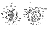
下記特許文献1〜3は、流体圧を利用した回転ダンパのうち、流体圧の制動力を可変する従来例である。図5(a)は文献1のものである。このダンパー構造は、ケーシング60が隔壁61を突設した円筒室62を有し、軸65がケーシング60に回転可能に組み付けられて、円筒室62に配置される軸部分に突設した回転翼66、及び回転翼66の先端側に移動自在に配置された可動体68を備えている。回転翼66は、先端に通路67を有し、該通路67を介し円筒室62の両側に連通可能にしている。可動体68は、略凹状でかつ通路67と連通する開口68aを凹状の片側に有していて、回転翼66の先端を凹状の内側にて覆った状態で、円筒室62の内周に沿って摺動可能に組み込まれている。なお、符号69a,69aは隔壁61の両側にある円筒室62の室内同士を連通している通路である。そして、この構造では、軸65が時計回りに回転され(以下、正転又はR回転と略称)るときには、粘性流体が可動体68の対応片側で通路67を閉じて制動力を増大する。軸65が反時計回りに回転され(以下、逆転又はL回転と略称)るときには、粘性流体が同図の左側筒室62より可動体68の通路68a、回転翼66の通路67、同図の右側筒室62へ漏れるため制動力を減じる。以上の弁構造は、特開平7−301272号や特開2000−120748号記載のものと類似している。
また、図5(b)は文献2のものである。このダンパー構造において、回転翼66は、立壁66a,66aから構成され、両立壁66aのうち、一方の基部に設けられて縦溝67に連通する通路67aを有している。可動体68は、縦溝67に対し上下摺動する板厚をなし、下両側に通路67aと対応する切欠部68aを有している。符号61aは隔壁61に設けられたオリフィスである。そして、この構造において、軸65がL回転のときは、粘性流体が通路67aから縦溝67に導入され、可動体68がその導入流体圧を切欠部68aで受けて軸心側から外側へ押圧され、図の上側のごとく縦溝67から突出して円筒室62の内周面に当接することにより制動力を増大する。R回転のときは、粘性流体が円筒室62の内周面と立壁66a及び可動体68の先端との間の隙間から漏れるため、可動体68が図の下側のごとく縦溝67内に退避して制動力を減じる。
【0003】
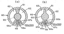
図6は文献3のものである。同(a)のダンパ構造は、上記に比較して、符号60と62がケーシング及び円筒室に対応し、符号61がケーシング60に組み付けられる軸65側の回転翼、符号66と68がケーシング側の隔壁と可動体に対応している。隔壁66は、両立壁66aから構成され、両立壁66aのうち、一方に通路67bを有している。可動体68は、両立壁66aの間に配置されて円筒室62の内周面に摺接し、又、両立壁66aの隙間内で周方向に摺動すると共に通路68aを有している。そして、軸65がL回転のときは粘性流体が左側立壁66aと内周面との間の隙間、可動体68の通路68a、右側立壁66aの通路67bを通って漏れるため制動力を減じる。R回転のときは粘性流体が左側立壁66aの通路67bや内周面との間の隙間から両立壁66a内に導入され、可動体68が該導入流体により左側立壁66aに当たるまで動かされて通路68aを閉じるため制動力を増大する。また、同(b)の構造において、隔壁66は、立壁66a,66a及び軸65側に摺接される連結部66bから構成され、両立壁66aに通路67c,67dを有している。可動体68は、基端が連結部66bの嵌合部に係合し、該係合箇所を支点として揺動され、又、先端が円筒室62の内周面に摺接すると共に通路68aを有している。軸65がL回転のときは粘性流体が左側立壁66aの通路67d、可動体68の通路68a、右側立壁66aの通路67cを経由して漏れるため制動力を減じる。R回転のときは粘性流体が通路67cから両立壁66a内に導入され、可動体68が該導入流体により動かされて左側立壁66aに当接して通路67dを閉じるため制動力を増大する。
【0004】
【特許文献1】
特開平8−303513号公報
【特許文献2】
特開平10−205567号公報
【特許文献3】
特開2001−50326号公報
【0005】
【発明が解決しようとする課題】
上記したように、従来構造では、それぞれ工夫された構成により制動力を可変するようにしているが、作動特性が安定維持されなかったり、量産時の加工性が悪くコスト高となる。即ち、図5(a)の構造では、ケーシング60の内周面を摺接する可動体68の摺動抵抗が作動時の粘性流体圧により設計値以上になり易く、作動特性が不安定となる。図5(b)の構造では、可動体68と縦溝67との間のはめ合い寸法精度が作動特性を左右し、例えば、可動体68が縦溝67に対し緩く係合していると、R回転されているにもかかわらず縦溝67から突出し易くなる。これに対し、図6(a),(b)の構造では、可動体68の移動量が少ない利点があるが、可動体68が円筒室62の内周面に摺接する構成であるため可動体68のはめ合い寸法精度が維持されていないと、作動特性が不安定となる。また、通路67b,67c,67dを隔壁66の軸方向略中間部に形成しなくてはならず造形が難しい。
【0006】
本発明の目的は、以上のような従来品に対し、部材間のはめ合い寸法精度を緩和したり製造容易にし、しかも作動特性を常に安定維持可能にする。
【0007】
【課題を解決するための手段】
上記目的を達成するために、請求項1の本発明は、図1〜図4の例で特定すると、ケーシング1が隔壁11を突設した円筒室12を有し、前記ケーシング1に組み付けられる軸2が前記円筒室12に配置される軸部分21に突設した回転翼23を有し、前記軸2の正転と逆転とで、前記円筒室12に充填された粘性流体より受ける制動力を可動体を介して可変する回転ダンパにおいて、前記ケーシング1が後付けされて前記円筒室12を内周面10と共に区画している側板3と、前記側板3の端面31と前記隔壁11の端面との対向した箇所に設けられて、前記隔壁11の両側にある前記円筒室12の室内同士を連通する通路(13a,32)とを有し、前記通路内に遊嵌した前記可動体5を介して、前記軸2が正転及び逆転の一方へ回転されるときに前記通路(13a,32)を閉状態に切り換え、他方へ回転されるときに前記通路(13a,32)を開状態を切り換えて制動力を可変することを特徴としている。
【0008】
(工夫点等)以上のダンパ構造は、課題に挙げたような問題を一掃する上で、ケーシングに後付け用の側板を設定し、該側板と隔壁との間に弁機構用の通路を設けるようにしたものである。具体的には、弁機構(通路及び可動体)を隔壁及び側板の対向箇所に設けることにより、例えば、各部材用の成形型を簡易化したり自動組立も実現容易にでき、同時に、通路内容積を固定して粘性流体圧の変動、引いては制動力の変動を確実に抑えることができ、しかも通路及び可動体の設計自由度を拡大できる等の利点が得られる。
【0009】
以上の発明は、請求項2〜3のごとく具体化されることが好ましい。
(請求項2)前記通路は、前記隔壁11の端面に設けられた切欠段溝13aと、前記側板3の端面31に設けられて前記隔壁11の端面と空間32を保って嵌合し(隔壁11の端面との間に空間32を保って嵌合する意味)、かつ前記切欠段溝13a及び前記空間32を通して前記隔壁11の両側にある前記円筒室10の室内同士を連通する凹所33とを有し、前記空間32に可動体5を配置している構成である。この構造では、図3に例示されるように、ケーシング1、側板3、軸2が共に簡易であり、成形型及び組立を単純化できて量産に最適なものとなる。また、可動体5は、図1(b),(c)のごとく空間32内で作動時の粘性流体圧により閉又は開位置へ動くが、この動きは従来と異なり内周面に対し摺接状態を保つことなく行われるため、制動力を安定化し易い。この場合は、前記凹所33の内面に一段低く設けられて可動体5によって密閉不能な略L形の逃げ溝34を有している(請求項3)と、例えば、隔壁11の両側にある円筒室10の両室内のうち逃げ溝34と通じている室内側と空間32との間における粘性流体の出入りを確実に維持でき、又、可動体5を単純な平板状にすることができる。
【0010】
【0011】
【0012】
【0013】
【発明の実施の形態】
本発明を適用した形態例について図面を参照し説明する。図1〜図3は第1形態を示し、図4はその変形例を示している。
【0014】
(概要)形態の回転ダンパは、ケーシング1が後付けされて内周面10及び軸2と共に円筒室12を区画している側板3、及び内周面10に一体に設けられて円筒室12内へ突出した隔壁11を有し、またケーシング1に回転可能に組み付けられる軸2が円筒室12に配置される軸部分21に突設した回転翼23を有し、さらに側板3の内端面31と隔壁11の端面との対向した箇所に設けられた弁機構である通路及び可動体5を有している。そして、軸2がR回転とL回転とで、円筒室12に充填された粘性流体より受ける制動力を可動体5を介して可変する。
また、図1及び図2に例示されるごとく、主部材がケーシング1と、軸2と、側板3と、カバー4と、可動体5〜7とから構成されている。該主部材は全て樹脂成形品であるが、材質的には樹脂以外でも差し支えない。
【0015】
ここで、ケーシング1は、有底筒形であり、内周面10が片端側の凹部10aを除き略同径となっている。内周面10には所定板厚の隔壁11が突設されている。軸2は、凹部10aに嵌合される枢軸部20と、円筒室12に対応した軸部分21と、軸部分21から延びてケーシング1外へ突出される軸部分22とからなる。軸部分21には回転翼23が突設されている。なお、軸2は、発明の回転ダンパを適用する蓋体等に直接連結してもよいし、軸側に設けられる連結穴等にシャフト9等を介し連結される。側板3は、略ドーナツ形状であり、外径の外側周囲に装着されたシール材(Oリング)S1、及び内径孔30の外側内周に装着されたシール材(Oリング)S2を有している。カバー4は、内径孔30と連続する孔40と、内周面10の開口内側に係合される部分41と、ケーシング1の端面と当接するフランジ部42と、フランジ部42に設けられた取付孔42a等を有している。なお、カバー4又はケーシング1の外面には、図示を省略したが、適用装置側への取付部等が設けられる。
【0016】
そして、上記した各部材は、一方向からの挿入操作により組立可能になるよう設計されている。即ち、各部材は、例えば、軸2をケーシング1の筒内に挿入した後、粘性流体(通常は、油)をケーシング1内に所定量注入したり、逆に、粘性流体を注入したケーシング1内に軸2を挿入する。次に、側板3を軸2の軸部分22に沿ってケーシング1内へ挿入し、最後にカバー4をケーシング1に不図示のねじ(取付孔42aから螺入されるねじ)等を介して装着すると、回転ダンパとして組み立てられる。組立状態において、側板3及びカバー4はケーシング1に対し固定であり、側板3の外周と内周面10との間がシール材S1を介し密封され、側板3の内径孔30と軸部分22との間がシール材S2を介し密封されている。円筒室12は、軸2の軸部分21と、内周面10と、凹部10aを含むケーシング1の片側内端面と、側板3の内端面31とにより区画形成され、又、固定側隔壁11を基準として回転翼23との間に形成される2つの室内に分割されている。軸2は、枢軸部20が凹部10aに枢支され、軸部分22が側板3の内径孔30に枢支されており、図2(b)のごとく回転翼23が粘性流体の抵抗を受けながら正逆回転される。以上の形態において、側板3は、後述する内端面31の凹所33が隔壁11の対向端面と隙間を持って嵌合し、又、凹所33以外の側板端面が軸側回転翼23の対応端面と当接する構造となっているため、回転翼23の両端側の隙間を最適に調整し制動力を安定維持し易い利点がある。これは、側板を持たない従来形態、つまり図2のカバー4に相当する閉じ部材をケーシング側に直に組み付ける構造だと、部材同士の寸法誤差により、前記閉じ部材と回転翼及び隔壁との間の隙間が小さくなり過ぎて制動力が過剰になったり、逆に、隙間が大きくなり過ぎて所定制動力を維持できなくなるが、そのような問題を解消できることを意味する。具体的には、前記した回転翼23及び隔壁11、側板3、カバー4の配列形態により、部材同士が寸法誤差を有していても、ケーシング1に対するカバー4の(ねじ等による)締め付け度合で側板3を動かして前記隙間を簡単に最適状態に調整できるためである。
【0017】
【0018】
【0019】
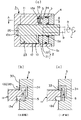
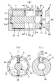
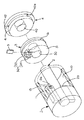
(要部)図1(a)は回転ダンパの縦断面図、同(b)と(c)は(a)のA−A線に沿った要部の拡大断面図である。図2(a)は部材関係を示す分解断面図、同(b)は(a)のB−B線に沿った断面図、同(c)は(a)のC−C線に沿った断面図である。図3は部材関係を示す外観図である。この形態の弁機構は、隔壁11の端面に設けられた切欠段溝13aと、側板3の内端面31に設けられて隔壁11の端面との間に空間32を形成する凹所33と、空間32に配置される可動体5とからなる。ここで、切欠段溝13aは、隔壁11の端面の一部及び隔壁11の一方の側面に開口した欠如部として形成されている。凹所33は、隔壁11の端面を受け入れて、隔壁11の端面側との間に所定大の空間32を形成する大きさである。凹所33の内面には、片側に一段低くなった細い略L形の逃げ溝34が設けられている。つまり、切欠段溝13a及び凹所33は、間に通路及び可動体収容用の空間32を形成する嵌合関係にある。同時に、該嵌合状態において、切欠段溝13aが隔壁11を基準として分割される円筒室12の両室内の一方と空間32とを連通すること、空間32が隔壁11を基準として分割される円筒室12の両室内の他方と連通することが必須となる。可動体5は、逃げ溝34の溝幅より大きな略矩形チップ状をなし、前記嵌合状態において、空間32に遊嵌されており、上側が内周面10の対応部で、下側が軸部分22の対応部で抜け止めされている。なお、可動体5の組込は、例えば、側板3がケーシング1内に所定量挿入された段階で、凹所33に入れるだけでよい。
【0020】
以上の弁機構を備えた回転ダンパにおいて、軸2がL回転のときには、図1(c)のごとく粘性流体が凹所33および逃げ溝34から空間32内に導入され、可動体5が該導入流体圧を受けて可動され、切欠段溝13aを閉状態にして制動力を増大する。R回転のときには、図1(b)のごとく粘性流体が切欠段溝13aから空間32内に導入され、可動体5が該導入流体圧で可動されて、切欠段溝13aを開状態にして、粘性流体が該切欠段溝13a、空間32を形成している凹所33および逃げ溝33を通って漏れるため、その漏れに比例して制動力を減じる。これにより、軸2及びこれに連結される蓋体等は、相対的に弱くなった制動力によって速く回転される。この利点は、制動力の作動切換を簡易かつ簡明な構成により実現し、可動体5が位置固定された通路(切欠段溝13a、空間32)に配置され、かつ、従来のような摺接状態で可動されないため、制動力が不安定にならず性能を向上できる。
【0021】
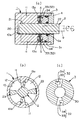
(変形例)図4は回転翼23及び隔壁11が複数構成の例であり、軸2の回転範囲(回転角)が小さな場合に採用される。即ち、この構造は、隔壁11が内周面10に対に突設され、又、回転翼23が軸部分21に対に突設されている態様において、各隔壁11の内端面が切欠段溝13aを異方向に形成し、かつ、側壁3の内端面31が各隔壁11に対応して凹所33及び逃げ溝34を形成している。従って、弁機構としては、2枚の可動体5が対応する空間32に配置され、切欠段溝13a及び空間32で形成される各通路を同時に開閉するため、制動力が相対的に大きくなる。
【0022】
【0023】
【0024】
【0025】
【0026】
なお、本発明は、請求項で特定される要件を具備しておればよく、細部的には種々変形可能なものである。
【0027】
【発明の効果】
以上説明したように、本発明に係る回転ダンパは次のような利点を有している。(1)、ケーシングに後付け用の固定側板を設定し、該側板と隔壁との対向箇所に可動体を遊嵌する通路、つまり位置固定された通路を設けることから、例えば、図6の従来品に比べて各部材の成形型を簡略化したり組立も改善し易くなる。
(2)、可動体が通路形成用空間内で遊嵌されて流体圧により動いて作動切換するため、従来品のごとく摺接状態を保つ形式より制動力を設計通り維持し易く、制動力を常に安定化できる。
(3)、回転翼や隔壁の高さ寸法にぱらつきがあっても、弁機構(可動体及び通路)による制動力や作動切換に影響せず、又、該制動力を側板の存在により調整することも容易となる。
【図面の簡単な説明】
【図1】 本発明に係る回転ダンパの形態を示す模式図である。
【図2】 上記回転ダンパの構成部材同士の関係を示す断面図である。
【図3】 上記回転ダンパの構成部材同士の関係を示す概略外観図である。
【図4】 上記形態の変形例を示す模式図である。
【図5】 回転ダンパの従来例を示す模式図である。
【図6】 回転ダンパの他の従来例を示す模式図である。
【符号の説明】
1…ケーシング(10は内周面、12は円筒室)
2…軸(21は円筒室に配置される軸部分)
3…側板(31は端面又は内端面)
4…蓋体
5…可動体
8…調整部材
11…隔壁
13a…切欠段溝(通路)
32…空間(33は凹所、34は逃げ溝)[0001]
BACKGROUND OF THE INVENTION
The present invention relates to a fluid rotary damper that varies a braking force between forward rotation and reverse rotation.
[0002]
[Prior art]
The following Patent Documents 1 to 3 are conventional examples in which the braking force of the fluid pressure is varied among the rotary dampers using the fluid pressure. FIG. 5 ( a) is that of Document 1. In this damper structure, a
FIG. 5B is that of
[0003]
FIG. 6 is that of
[0004]
[Patent Document 1]
JP-A-8-303513 [Patent Document 2]
Japanese Patent Laid-Open No. 10-205567 [Patent Document 3]
Japanese Patent Laid-Open No. 2001-50326
[Problems to be solved by the invention]
As described above, in the conventional structure, the braking force is varied by a devised configuration, but the operation characteristics are not stably maintained, the workability at the time of mass production is poor, and the cost is high. That is, in the structure of FIG. 5A, the sliding resistance of the
[0006]
The object of the present invention is to reduce the fitting dimensional accuracy between members and facilitate the manufacture of the conventional product as described above, and to make it possible to always maintain the operation characteristics stably.
[0007]
[Means for Solving the Problems]
In order to achieve the above object, the present invention of claim 1, as specified in the examples of FIGS. 1 to 4, has a
[0008]
(Deviation points, etc.) The above-described damper structure has a side plate for retrofitting in the casing, and a passage for the valve mechanism is provided between the side plate and the partition wall in order to eliminate the problems mentioned in the problem. It is a thing. Specifically, by providing a valve mechanism (passage and movable body) at opposite locations of the partition wall and the side plate, for example, the mold for each member can be simplified and automatic assembly can be easily realized, and at the same time, the volume of the passage It is possible to reliably suppress fluctuations in the viscous fluid pressure by pulling, and thus, fluctuations in the braking force, and to increase the design freedom of the passage and the movable body.
[0009]
The above invention is preferably embodied as in
(Claim 2) The passage is fitted in the
[0010]
[0011]
[0012]
[0013]
DETAILED DESCRIPTION OF THE INVENTION
Embodiments to which the present invention is applied will be described with reference to the drawings. 1 to 3 show a first embodiment, FIG. 4 shows the modification.
[0014]
(Summary) The rotary damper of the form is provided integrally with the
Moreover , as illustrated in FIGS. 1 and 2, the main member includes a casing 1, a
[0015]
Here, the casing 1 has a bottomed cylindrical shape, and the inner
[0016]
Each member described above is designed to be assembled by an insertion operation from one direction. That is, for example, after inserting the
[0017]
[0018]
[0019]
(Main part) FIG. 1A is a longitudinal sectional view of a rotary damper, and FIGS. 1B and 1C are enlarged cross-sectional views of the main part along the line AA in FIG. 2A is an exploded cross-sectional view showing the member relationship, FIG. 2B is a cross-sectional view taken along line BB in FIG. 2A, and FIG. 2C is a cross-section taken along line CC in FIG. FIG. FIG. 3 is an external view showing the member relationship. The valve mechanism of this form includes a
[0020]
In the rotary damper provided with the above valve mechanism, when the
[0021]
(Modification ) FIG. 4 shows an example in which the
[0022]
[0023]
[0024]
[0025]
[0026]
The present invention only needs to satisfy the requirements specified in the claims, and can be variously modified in detail.
[0027]
【The invention's effect】
As described above, the rotary damper according to the present invention has the following advantages. (1), setting a fixed side plates for retrofit to the casing, the passage loosely fitting the movable member to the opposite portion between the side plate and the partition wall, since the provision of the words positions fixed path, for example, conventional 6 Compared to the above, it becomes easy to simplify the molding die of each member and improve the assembly.
(2), since the movable body is operated changeover moved by loosely has been fluid pressure in between empty passage formed, easily maintained as designed the braking force from the format to maintain the sliding contact as the conventional products, the braking force Can always be stabilized.
(3) Even if there are variations in the height of the rotor blades and partition walls, it does not affect the braking force or operation switching by the valve mechanism (movable body and passage), and the braking force is adjusted by the presence of the side plate. It becomes easy.
[Brief description of the drawings]
1 is a schematic diagram showing the shape condition of the rotary damper according to the present invention.
FIG. 2 is a cross-sectional view showing the relationship between the constituent members of the rotary damper.
FIG. 3 is a schematic external view showing the relationship between the constituent members of the rotary damper.
4 is a schematic view showing a modified example above shape state.
FIG. 5 is a schematic view showing a conventional example of a rotary damper.
FIG. 6 is a schematic view showing another conventional example of a rotary damper.
[Explanation of symbols]
1 ... Casing (10 is an inner peripheral surface, 12 is a cylindrical chamber)
2 ... shaft (21 is a shaft portion arranged in the cylindrical chamber)
3 ... Side plate (31 is an end face or inner end face)
DESCRIPTION OF
32 ... space (33 is a recess, 34 is a relief groove)
Claims (3)
前記ケーシングが後付けされて前記円筒室を内周面と共に区画している側板と、前記側板の端面と前記隔壁の端面との対向した箇所に設けられて、前記隔壁の両側にある前記円筒室の室内同士を連通する弁機構用の通路とを有し、
前記通路内に遊嵌した前記可動体を介して、前記軸が正転及び逆転の一方へ回転されるときに前記通路を閉状態に切り換え、他方へ回転されるときに前記通路を開状態を切り換えて制動力を可変することを特徴とする回転ダンパ。The casing has a cylindrical chamber projecting a partition wall, and a shaft assembled to the casing has a rotor blade projecting from a shaft portion disposed in the cylindrical chamber, and the forward rotation and the reverse rotation of the shaft, a braking force received from the viscous fluid filled in the cylinder chamber through the movable member in a rotary damper for variably,
A side plate in which the casing is partitioned with an inner peripheral surface of said cylindrical chamber being retrofitted, provided opposing portions between the end face and the end face of the partition wall of the side plate, of the cylindrical chamber on either side of the partition wall and a passage for the valve mechanism for communicating the chamber with each other,
Via the movable body loosely fitted in the passage, the passage is switched to a closed state when the shaft is rotated in one of normal rotation and reverse rotation, and the passage is opened when the shaft is rotated in the other direction. A rotary damper characterized in that the braking force is changed by switching.
Priority Applications (1)
| Application Number | Priority Date | Filing Date | Title |
|---|---|---|---|
| JP2003076720A JP4144792B2 (en) | 2003-03-20 | 2003-03-20 | Rotating damper |
Applications Claiming Priority (1)
| Application Number | Priority Date | Filing Date | Title |
|---|---|---|---|
| JP2003076720A JP4144792B2 (en) | 2003-03-20 | 2003-03-20 | Rotating damper |
Publications (2)
| Publication Number | Publication Date |
|---|---|
| JP2004286073A JP2004286073A (en) | 2004-10-14 |
| JP4144792B2 true JP4144792B2 (en) | 2008-09-03 |
Family
ID=33291658
Family Applications (1)
| Application Number | Title | Priority Date | Filing Date |
|---|---|---|---|
| JP2003076720A Expired - Fee Related JP4144792B2 (en) | 2003-03-20 | 2003-03-20 | Rotating damper |
Country Status (1)
| Country | Link |
|---|---|
| JP (1) | JP4144792B2 (en) |
Families Citing this family (6)
| Publication number | Priority date | Publication date | Assignee | Title |
|---|---|---|---|---|
| JP4911684B2 (en) * | 2006-07-28 | 2012-04-04 | 日立粉末冶金株式会社 | Rotating damper |
| JP5031505B2 (en) * | 2007-10-03 | 2012-09-19 | 不二ラテックス株式会社 | Rotating damper device |
| JP5289363B2 (en) * | 2010-03-16 | 2013-09-11 | 株式会社ニフコ | Rotary damper |
| JP6167268B2 (en) * | 2013-08-09 | 2017-07-26 | 株式会社Tok | Torque automatic adjustment type rotary damper |
| WO2022113372A1 (en) * | 2020-11-30 | 2022-06-02 | エレファンテック株式会社 | Resin assembly product and production method |
| CN114508557B (en) * | 2022-02-16 | 2024-01-16 | 江苏朗域电力科技有限公司 | Viscous rotary damper |
-
2003
- 2003-03-20 JP JP2003076720A patent/JP4144792B2/en not_active Expired - Fee Related
Also Published As
| Publication number | Publication date |
|---|---|
| JP2004286073A (en) | 2004-10-14 |
Similar Documents
| Publication | Publication Date | Title |
|---|---|---|
| CN101821531B (en) | Hinge device | |
| CN1221746C (en) | Rotating damper | |
| CN101836009B (en) | Damper and door handle with the damper | |
| JPH07301272A (en) | Fluid pressure damper | |
| JP4144792B2 (en) | Rotating damper | |
| CN117006185B (en) | Damping device and valve comprising same | |
| US8523548B2 (en) | Screw compressor having a gate rotor assembly with pressure introduction channels | |
| EP1489334B1 (en) | Rotary damper | |
| JP2009103218A (en) | Damper | |
| KR930010467B1 (en) | Variable displacement vane compressor | |
| JP4144785B2 (en) | Rotating damper | |
| JP2004068993A (en) | Rotary damper | |
| JP3981172B2 (en) | Rotating damper | |
| JP4625451B2 (en) | Rotary damper | |
| KR101534156B1 (en) | Door damper for shock absorption | |
| EP4269736A1 (en) | Door actuator | |
| JP2004068992A (en) | Rotary damper | |
| JPH07119781A (en) | Rotary damper | |
| JP4947720B2 (en) | Rotating damper | |
| JP7346132B2 (en) | fluid damper device | |
| JP2000046087A (en) | Rotary damper | |
| JP2006342857A (en) | Rotary damper | |
| JP3067911U (en) | Rotary damper | |
| CN108577647B (en) | Damper | |
| JP7246607B2 (en) | floor hinge |
Legal Events
| Date | Code | Title | Description |
|---|---|---|---|
| A621 | Written request for application examination |
Free format text: JAPANESE INTERMEDIATE CODE: A621 Effective date: 20050927 |
|
| A977 | Report on retrieval |
Free format text: JAPANESE INTERMEDIATE CODE: A971007 Effective date: 20071214 |
|
| A131 | Notification of reasons for refusal |
Free format text: JAPANESE INTERMEDIATE CODE: A131 Effective date: 20080204 |
|
| A521 | Written amendment |
Free format text: JAPANESE INTERMEDIATE CODE: A523 Effective date: 20080403 |
|
| TRDD | Decision of grant or rejection written | ||
| A01 | Written decision to grant a patent or to grant a registration (utility model) |
Free format text: JAPANESE INTERMEDIATE CODE: A01 Effective date: 20080613 |
|
| A01 | Written decision to grant a patent or to grant a registration (utility model) |
Free format text: JAPANESE INTERMEDIATE CODE: A01 |
|
| A61 | First payment of annual fees (during grant procedure) |
Free format text: JAPANESE INTERMEDIATE CODE: A61 Effective date: 20080613 |
|
| R150 | Certificate of patent or registration of utility model |
Ref document number: 4144792 Country of ref document: JP Free format text: JAPANESE INTERMEDIATE CODE: R150 Free format text: JAPANESE INTERMEDIATE CODE: R150 |
|
| FPAY | Renewal fee payment (event date is renewal date of database) |
Free format text: PAYMENT UNTIL: 20110627 Year of fee payment: 3 |
|
| FPAY | Renewal fee payment (event date is renewal date of database) |
Free format text: PAYMENT UNTIL: 20110627 Year of fee payment: 3 |
|
| FPAY | Renewal fee payment (event date is renewal date of database) |
Free format text: PAYMENT UNTIL: 20120627 Year of fee payment: 4 |
|
| FPAY | Renewal fee payment (event date is renewal date of database) |
Free format text: PAYMENT UNTIL: 20120627 Year of fee payment: 4 |
|
| FPAY | Renewal fee payment (event date is renewal date of database) |
Free format text: PAYMENT UNTIL: 20130627 Year of fee payment: 5 |
|
| S111 | Request for change of ownership or part of ownership |
Free format text: JAPANESE INTERMEDIATE CODE: R313111 |
|
| R350 | Written notification of registration of transfer |
Free format text: JAPANESE INTERMEDIATE CODE: R350 |
|
| LAPS | Cancellation because of no payment of annual fees |