JP4142829B2 - Camera swivel - Google Patents
Camera swivel Download PDFInfo
- Publication number
- JP4142829B2 JP4142829B2 JP30862599A JP30862599A JP4142829B2 JP 4142829 B2 JP4142829 B2 JP 4142829B2 JP 30862599 A JP30862599 A JP 30862599A JP 30862599 A JP30862599 A JP 30862599A JP 4142829 B2 JP4142829 B2 JP 4142829B2
- Authority
- JP
- Japan
- Prior art keywords
- stepping motor
- camera
- turning
- information
- current
- Prior art date
- Legal status (The legal status is an assumption and is not a legal conclusion. Google has not performed a legal analysis and makes no representation as to the accuracy of the status listed.)
- Expired - Lifetime
Links
Images


Landscapes
- Studio Devices (AREA)
- Control Of Stepping Motors (AREA)
Description
【0001】
【発明の属する技術分野】
この発明は、ステッピングモータによりカメラを旋回するカメラの旋回装置に関するものである。
【0002】
【従来の技術】
従来、監視用などのカメラの旋回装置では、ステッピングモータが使用されており、必要な角度の旋回が的確に行われている。
【0003】
しかしながら、旋回装置は屋外に設置される場合も多く、雪や風、更には氷結など外的気象条件により旋回トルクの不足が発生し、ステッピングモータが脱調(空回り)することがあり、所望の方向へカメラを向けることができないなどの問題が発生する。
【0004】
【発明が解決しようとする課題】
本発明は上記のような従来のカメラの旋回装置が有する問題点を解決せんとしてなされたもので、その目的は、外的条件の変化に合わせてトルク不足の解消を図ることができるカメラの旋回装置を提供することである。また、他の目的は、脱調が生じた場合に適切に補正を行うことのできるカメラの旋回装置を提供することである。
【0005】
【課題を解決するための手段】
本発明に係るカメラの旋回装置は、ステッピングモータによりカメラを旋回するカメラの旋回装置において、遠隔制御装置から到来する前記ステッピングモータに対する加速情報に基づき、前記ステッピングモータの回転速度制御を行う速度制御手段を具備することを特徴とする。これにより、遠隔からステッピングモータの加速度を制御でき、所要の旋回トルクによるカメラの旋回を行うことが可能となる。
【0014】
また、本発明に係るカメラの旋回装置は、ステッピングモータによりカメラを旋回するカメラの旋回装置において、この旋回装置の周囲の風速情報を得るための風速計と、この風速計により得られた風速情報に基づき前記ステッピングモータへの励磁電流制御を行う電流制御手段とを具備し、励磁電流の変化により前記ステッピングモータの発熱を制御することを特徴とする。これにより、風速に応じて励磁電流制御がなされ、ステッピングモータの発熱制御を行うことが可能となる。
【0015】
また、本発明に係るカメラの旋回装置は、ステッピングモータによりカメラを旋回するカメラの旋回装置において、この旋回装置の周囲の温度情報を得るための温度計と、この温度計により得られた温度情報に基づき前記ステッピングモータへの励磁電流制御を行う電流制御手段とを具備し、励磁電流の変化により前記ステッピングモータの発熱を制御することを特徴とする。これにより、周囲の温度に応じて励磁電流制御がなされ、ステッピングモータの発熱制御を行うことが可能となる。
【0016】
【発明の実施の形態】
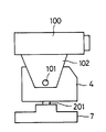
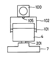
以下、添付図面を参照して本発明の実施の形態に係るカメラの旋回装置を説明する。各図において同一の構成要素には、同一の符号を付して重複する説明を省略する。本実施における全ての形態に係る監視用カメラ装置は、図1、図2に示されるように、基台7の上に旋回筐体4を設けて軸201を中心として水平方向に回動可能としている。また、旋回筐体4に載置板102を設けて監視カメラ100を載置し、ネジ105により固定する。載置板102は、軸101を中心として回転する構造となっている。載置板102の回転に応じて監視カメラ100が回転し、監視カメラ100の視野を上下方向に変更可能とされている。
【0017】
旋回筐体4内には、以下の各実施の形態に示されるように、旋回の動力源であるステッピングモータが設けられている。ステッピングモータの軸にはウォームギアが取り付けられ、このウォームギアには、軸201(図1、図2)を持つウォームホイルが結合されるなどの構成により旋回が行われる。
【0018】
(実施の形態1)
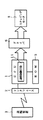
この実施の形態は、図3に示されるように、遠隔装置3から制御情報を送信可能に構成されている。旋回筐体4内には、上記遠隔装置3に接続されるインターフェース2と、CPU1、ROM5、ドライバ6、ステッピングモータ8が設けられている。
【0019】
上記のステッピングモータ8は、図1、図2の軸101、201に対する回転を与えるものであり、ドライバ6はCPU1の制御の基にステッピングモータ8の駆動制御を行う。ROM5には、ステッピングモータ8を駆動する際の制御に関し、加速特性、最高速度等に関するデフォルト値などの情報が記憶されており、CPU1はこのROM5に記憶された情報を用いてステッピングモータ8の駆動制御をドライバ6へ指示する。
【0020】
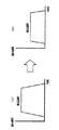
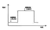
例えば、ROM5には、図4(a)に示す最高速度の情報と、加速時間t1において最高速度とする加速特性の情報が格納されており、通常状態においてはこの情報に基づきCPU1はステッピングモータ8の駆動制御をドライバ6へ指示している。
【0021】
これに対し、冬季には、遠隔装置3から管理者がステッピングモータ8の加速特性の情報と最高速度の情報とを入力して送信する。この加速特性の情報と最高速度の情報とは、インターフェース2を介してCPU1により受け取られる。CPU1は、これらの情報を保持し、遠隔装置3による設定の有りを示すフラグをセットし、ROM5に記憶された情報に代えて上記加速特性の情報と最高速度の情報を用いてステッピングモータ8の駆動制御をドライバ6へ指示する速度制御手段11として機能する。
【0022】
上記の結果、ROM5に記憶された情報に基づき加速特性が図4(a)に示されるように制御されていたのに対し、遠隔装置3から送られた加速特性の情報に基づき図4(b)に示されるように制御がなされる。つまり、加速時間t2(t2>t1) において最高速度へ到るようにする加速特性の情報に基づきCPU1はステッピングモータ8の駆動制御をドライバ6へ指示している。この結果、加速レートが下がり、加速時の旋回トルクを上昇させることができ、脱調を防止できる。
【0023】
また、最高速度についてもROM5に記憶された情報に基づき最高速度が図5(a)に示されるように制御されていたのに対し、遠隔装置3から送られた最高速度の情報に基づき図5(b)に示されるように、より小さな最高速度にて回転が行われるように制御がなされる。この結果、旋回の最高速度(定常状態の速度)が通常時より下がり、最高速度により旋回がなされる場合の旋回トルクを上昇させることができ、脱調を防止できる。尚、通常状態に戻す場合には、遠隔装置3から復旧の指示を送信し、セットされているフラグをリセットする。
【0024】
(実施の形態2)
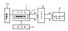
この実施の形態は、図6に示されるようにCPU1に風速計21が接続されたものであり、CPU1には、風速計21により得られた風速情報に基づきステッピングモータ8の回転速度制御を行う速度制御手段12が具備されている。速度制御手段12は、例えば各風速の値と、加速特性の値及び最高速度の値を、対応付けたメモリテーブルを有し、風速計21により得られた風速情報を基に上記メモリテーブルを検索して対応する加速特性の値及び最高速度の値を求め、この値に対応して実施の形態1において説明した通りの制御を行う。
【0025】
上記メモリテーブルには、風速が大きくなる程に加速レートと最高速度が低下するように情報が書き込まれており、風速が大きくなるにつれて加速レートと最高速度が下がり、加速時の旋回トルクと最高速度により旋回がなされる場合の旋回トルクを上昇させることができ、脱調を防止できる。尚、所定以下の風速の場合には、ROM5に記憶された情報によりステッピングモータ8の回転制御を行うものとする。
【0026】
(実施の形態3)
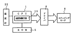
この実施の形態は、図7に示されるようにCPU1に温度計22が接続されたものであり、CPU1には、温度計22により得られた温度情報に基づきステッピングモータ8の回転速度制御を行う速度制御手段13が具備されている。速度制御手段13は、例えば各温度の値と、加速特性の値及び最高速度の値を、対応付けたメモリテーブルを有し、温度計22により得られた温度情報を基に上記メモリテーブルを検索して対応する加速特性の値及び最高速度の値を求め、この値に対応して実施の形態1において説明した通りの制御を行う。
【0027】
上記メモリテーブルには、温度が大きくなる程に加速レートと最高速度が低下するように情報が書き込まれており、温度が大きくなるにつれて加速レートと最高速度が下がり、加速時の旋回トルクと最高速度により旋回がなされる場合の旋回トルクを上昇させることができ、脱調を防止できる。尚、所定以下の温度の場合には、ROM5に記憶された情報によりステッピングモータ8の回転制御を行うものとする。
【0028】
(実施の形態4)
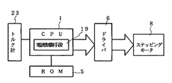
この実施の形態は、図8に示されるようにCPU1に、ステッピングモータ8のトルクを計測するトルク計23が接続されたものであり、CPU1には、トルク計23により得られたトルク情報に基づきステッピングモータ8の回転速度制御を行う速度制御手段14が具備されている。速度制御手段14は、例えば各トルクの値と、加速特性の値及び最高速度の値を、対応付けたメモリテーブルを有し、トルク計23により得られたトルク情報を基に上記メモリテーブルを検索して対応する加速特性の値及び最高速度の値を求め、この値に対応して実施の形態1において説明した通りの制御を行う。
【0029】
上記メモリテーブルには、トルクが大きくなる程に加速レートと最高速度が低下するように情報が書き込まれており、トルクが大きくなるにつれて加速レートと最高速度が下がり、加速時の旋回トルクと最高速度により旋回がなされる場合の旋回トルクを上昇させることができ、脱調を防止できる。尚、所定以下のトルクの場合には、ROM5に記憶された情報によりステッピングモータ8の回転制御を行うものとする。
【0030】
上記トルク計23は、前述のウォームギア等の伝動軸の捩じれを機械的、光学的に或いは磁気歪みなどにより測定する他、例えば、図9に示されるように、ステッピングモータ8の回転を伝動ベルト31により監視カメラ100の旋回を行うようにし、伝動ベルト31のトルク反力を歪み計32により捕らえる構成のものを採用できる。
【0031】
(実施の形態5)
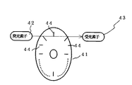
この実施の形態では、ステッピングモータ8に位置情報検出手段33が設けられている。この位置情報検出手段33は、ステッピングモータ8の回転軸に取り付けられる図11に示すようなスリット板41と、発光素子42と受光素子43により構成することができる。スリット板41の円周縁には、放射状に多数のスリット44が所定間隔にて穿設されており、ドライバ6から1パルスの出力がステッピングモータ8へ与えられるごとに、スリット板41が所定の角度θ回転するから、ドライバ6からNパルスがステッピングモータ8へ与えられると、スリット板41が回転する角度はNθとなる。このスリット板41が角度Nθだけ回転するときに、M個のスリット44が発光素子42と受光素子43との間を通過することにより、M個のパルスが得られる。
【0032】
上記で、例えば、Mが1のときNが10とする。つまり、ドライバ6から10パルスの出力がステッピングモータ8へ与えられるごとに、受光素子43から1パルスが得られるとする。係る条件の下では、正常時(ステッピングモータ8に脱調が生じていないとき)には、図12に示されるように、ドライバ6からnパルスの出力がステッピングモータ8へ与えられたときに、受光素子43からmパルスが得られ、10(m−1)≦n<10mなる関係が成立する。
【0033】
これに対し、脱調が生じると、ドライバ6から出力されるパルス数に対して、受光素子43から得られるパルス数の比が少なくなり、10m≦nなる関係が成立するようになる。
【0034】
CPU1の脱調検出手段15は、上記の関係から脱調の発生の有無を検出し、CPU1の補正制御手段16が、脱調検出手段15による脱調の発生有の検出を受けて10(m−1)≦n<10mなる関係が成立するように更にドライバ6へ制御を行う。これにより、旋回による位置補正を行い監視カメラ100の向きを適切な方向へ向けることができる。
【0035】
尚、上記において、脱調検出手段15による脱調の発生有の検出を受けた場合には、既に説明の通り加速特性や最高速度を低下させ、十分な旋回トルクを得て旋回動作を行わせると良い。加速特性や最高速度をどの程度低下させるかについては、ドライバ6から出力されるパルス数に対する受光素子43から得られるパルス数の比や、差に応じるようにする。
【0036】
(実施の形態6)
この実施の形態は、図13に示すようにCPU1にはステッピングモータ8の駆動電流を変更するようにドライバ6へ制御を行う電流制御手段17が具備されている。電流制御手段17は、例えば各風速の値と駆動電流を対応付けたメモリテーブルを有し、風速計21により得られた風速情報を基に上記メモリテーブルを検索して対応する値の駆動電流を求め、この対応の駆動電流値となるようにドライバ6からステッピングモータへ流す駆動電流を制御する。
【0037】
上記メモリテーブルには、風速が大きくなる程に駆動電流が大きくなるように情報が書き込まれており、風速が大きくなるにつれて旋回トルクを上昇させることができ、脱調を防止できる。尚、駆動電流は、図16に示すように、ステッピングモータ8が回転するときに流れる電流であり、これに対し、ステッピングモータ8の回転が停止しているときに流れる電流を励磁電流という。
【0038】
(実施の形態7)
この実施の形態は、図14に示すようにCPU1にはステッピングモータ8の駆動電流を変更するようにドライバ6へ制御を行う電流制御手段18が具備されている。電流制御手段18は、例えば各温度の値と駆動電流を対応付けたメモリテーブルを有し、温度計22により得られた温度情報を基に上記メモリテーブルを検索して対応する値の駆動電流を求め、この対応の駆動電流値となるようにドライバ6からステッピングモータ8へ流す駆動電流を制御する。
【0039】
上記メモリテーブルには、温度が低くなる程に駆動電流が大きくなるように情報が書き込まれており、温度が低くなるにつれて旋回トルクを上昇させることができ、脱調を防止できる。
【0040】
(実施の形態8)
この実施の形態は、図15に示すようにCPU1にはステッピングモータ8の駆動電流を変更するようにドライバ6へ制御を行う電流制御手段19が具備されている。電流制御手段19は、例えばトルクの値と駆動電流を対応付けたメモリテーブルを有し、トルク計23により得られた温度情報を基に上記メモリテーブルを検索して対応する値の駆動電流を求め、この対応の駆動電流値となるようにドライバ6からステッピングモータ8へ流す駆動電流を制御する。
【0041】
上記メモリテーブルには、トルクが大きくなる程に駆動電流が大きくなるように情報が書き込まれており、トルクが大きくなるにつれて旋回トルクを上昇させることができ、脱調を防止できる。
【0042】
(実施の形態9)
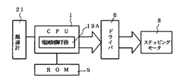
この実施の形態の構成は図17に示す通りである。この電流制御手段19Aは、例えば各風速の値と励磁電流を対応付けたメモリテーブルを有し、風速計21により得られた風速情報を基に上記メモリテーブルを検索して対応する値の励磁電流を求め、ステッピングモータ8の回転が停止している状態において上記にて求めた値の電流値となるようにドライバ6からステッピングモータ8へ流す励磁電流を制御する。
【0043】
上記メモリテーブルには、風速が大きくなる程に励磁電流が大きくなるように情報が書き込まれており、風速が大きくなるにつれて励磁電流が大きくなり、ステッピングモータ8の発熱が大きくなり、例えば冬場などにおいて風による冷却を防止できる。
【0044】
(実施の形態10)
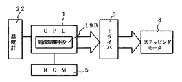
この実施の形態の構成は図18に示す通りである。この電流制御手段19Bは、例えば各温度の値と励磁電流を対応付けたメモリテーブルを有し、温度計22により得られた温度情報を基に上記メモリテーブルを検索して対応する値の励磁電流を求め、ステッピングモータ8の回転が停止している状態において上記にて求めた値の電流値となるようにドライバ6からステッピングモータ8へ流す励磁電流を制御する。
【0045】
上記メモリテーブルには、温度が低くなる程に励磁電流が大きくなるように情報が書き込まれており、温度が低くなるにつれて励磁電流が大きくなり、ステッピングモータ8の発熱が大きくなり、例えば冬場における温度低下時の凍結を防止できる。
【0046】
尚、実施の形態9と実施の形態10では、センサからの入力に応じて励磁電流を制御するようにしたが、手動により励磁電流の設定を行うようにしても良い。例えば、冬場には夏場よりも大きな励磁電流を流すように、CPU1へディップスイッチ等により設定を行い、ステッピングモータ8の回転が停止している状態において大きな励磁電流値となるようにドライバ6からステッピングモータ8へ流すことで凍結などを防ぐようにする。
【0047】
【発明の効果】
以上説明したように本発明に係るカメラの旋回装置によれば、ステッピングモータによりカメラを旋回するカメラの旋回装置において、遠隔制御装置から到来する前記ステッピングモータに対する加速情報に基づき、前記ステッピングモータの回転速度制御を行う速度制御手段を具備するので、遠隔からステッピングモータの加速度を制御でき、所要の旋回トルクによるカメラの旋回を行うことが可能となり、脱調の発生を防止することができる。
【0056】
また、本発明に係るカメラの旋回装置によれば、ステッピングモータによりカメラを旋回するカメラの旋回装置において、この旋回装置の周囲の風速情報を得るための風速計と、この風速計により得られた風速情報に基づき前記ステッピングモータへの励磁電流制御を行う電流制御手段とを具備するので、風速に応じて励磁電流制御がなされ、励磁電流が大きくなるにつれてステッピングモータの発熱を高くすることができ、強風による温度低下による旋回始動時の不具合発生を防止できる。
【0057】
また、本発明に係るカメラの旋回装置は、ステッピングモータによりカメラを旋回するカメラの旋回装置において、この旋回装置の周囲の温度情報を得るための温度計と、この温度計により得られた温度情報に基づき前記ステッピングモータへの励磁電流制御を行う電流制御手段とを具備するので、温度に応じて励磁電流制御がなされ、励磁電流が大きくなるにつれてステッピングモータの発熱を高くすることができ、温度低下による凍結などの不具合発生を防止できる。
【図面の簡単な説明】
【図1】本発明で用いられる監視カメラ装置の側面図。
【図2】本発明で用いられる監視カメラ装置の正面図。
【図3】本発明の第1の実施の形態のブロック図。
【図4】本発明の第1の実施の形態による加速特性の変更を説明するための図。
【図5】本発明の第1の実施の形態による最高速度の変更を説明するための図。
【図6】本発明の第2の実施の形態のブロック図。
【図7】本発明の第3の実施の形態のブロック図。
【図8】本発明の第4の実施の形態のブロック図。
【図9】本発明の第4の実施の形態に用いられるトルク計の説明図。
【図10】本発明の第5の実施の形態のブロック図。
【図11】本発明の第5の実施の形態に用いられる要部の構成を示す図。
【図12】本発明の第5の実施の形態における動作を説明する図。
【図13】本発明の第6の実施の形態のブロック図。
【図14】本発明の第7の実施の形態のブロック図。
【図15】本発明の第8の実施の形態のブロック図。
【図16】ステッピングモータの駆動電流と励磁電流とを説明する図。
【図17】本発明の第9の実施の形態のブロック図。
【図18】本発明の第10の実施の形態のブロック図。
【符号の説明】
1 CPU 2 インターフェース
3 遠隔装置 4 旋回筐体
5 ROM 6 ドライバ
7 基台 8 ステッピングモータ
11〜14 速度制御手段 15 脱調検出手段
16 補正手段 17〜19、19A、19B 電流制御手段
21 風速計 22 温度計
23 トルク計 31 伝動ベルト
32 歪み計 33 位置情報検出手段[0001]
BACKGROUND OF THE INVENTION
The present invention relates to a camera turning device for turning a camera by a stepping motor.
[0002]
[Prior art]
2. Description of the Related Art Conventionally, in a camera turning device for monitoring or the like, a stepping motor is used, and turning at a required angle is accurately performed.
[0003]
However, swiveling devices are often installed outdoors, and due to external weather conditions such as snow, wind, and icing, the turning torque may be insufficient, and the stepping motor may step out (idle). Problems such as being unable to point the camera in the direction.
[0004]
[Problems to be solved by the invention]
The present invention has been made in order to solve the above-described problems of the conventional camera turning device, and its purpose is to turn the camera that can solve the shortage of torque in accordance with changes in external conditions. Is to provide a device. Another object of the present invention is to provide a camera turning device capable of appropriately correcting when a step-out occurs.
[0005]
[Means for Solving the Problems]
The camera turning device according to the present invention is a camera turning device for turning a camera by a stepping motor, and a speed control means for controlling the rotation speed of the stepping motor based on acceleration information for the stepping motor coming from a remote control device. It is characterized by comprising. Thereby, the acceleration of the stepping motor can be controlled from a remote location, and the camera can be turned with a required turning torque.
[0014]
The camera turning device according to the present invention includes an anemometer for obtaining wind speed information around the turning device in a camera turning device that turns the camera by a stepping motor, and wind speed information obtained by the anemometer. And a current control means for controlling the excitation current to the stepping motor based on the above, and the heat generation of the stepping motor is controlled by the change of the excitation current. Thereby, excitation current control is performed according to the wind speed, and it becomes possible to perform heat generation control of the stepping motor.
[0015]
The camera turning device according to the present invention includes a thermometer for obtaining temperature information around the turning device and a temperature information obtained by the thermometer in the turning device of the camera for turning the camera by a stepping motor. And a current control means for controlling the excitation current to the stepping motor based on the above, and the heat generation of the stepping motor is controlled by the change of the excitation current. As a result, excitation current control is performed in accordance with the ambient temperature, and heat generation control of the stepping motor can be performed.
[0016]
DETAILED DESCRIPTION OF THE INVENTION
A camera turning device according to an embodiment of the present invention will be described below with reference to the accompanying drawings. In the drawings, the same components are denoted by the same reference numerals and redundant description is omitted. As shown in FIG. 1 and FIG. 2, the surveillance camera device according to all the embodiments in the present embodiment is provided with a
[0017]
As shown in the following embodiments, a stepping motor, which is a turning power source, is provided in the turning
[0018]
(Embodiment 1)
In this embodiment, as shown in FIG. 3, control information can be transmitted from the
[0019]
The
[0020]
For example, the
[0021]
On the other hand, in winter, the manager inputs and transmits information on acceleration characteristics of the stepping
[0022]
As a result, the acceleration characteristic is controlled based on the information stored in the
[0023]
Also, the maximum speed is controlled based on the information stored in the
[0024]
(Embodiment 2)
In this embodiment, as shown in FIG. 6, an
[0025]
In the above memory table, information is written so that the acceleration rate and maximum speed decrease as the wind speed increases. As the wind speed increases, the acceleration rate and maximum speed decrease, and the turning torque and maximum speed during acceleration are reduced. Thus, the turning torque when turning can be increased, and step-out can be prevented. When the wind speed is less than a predetermined value, the rotation control of the stepping
[0026]
(Embodiment 3)
In this embodiment, as shown in FIG. 7, a
[0027]
In the memory table, information is written so that the acceleration rate and the maximum speed decrease as the temperature increases. The acceleration rate and the maximum speed decrease as the temperature increases, and the turning torque and the maximum speed during acceleration Thus, the turning torque when turning can be increased, and step-out can be prevented. When the temperature is lower than a predetermined temperature, the rotation of the stepping
[0028]
(Embodiment 4)
In this embodiment, as shown in FIG. 8, a
[0029]
In the above memory table, information is written so that the acceleration rate and the maximum speed decrease as the torque increases. The acceleration rate and the maximum speed decrease as the torque increases, and the turning torque and the maximum speed during acceleration Thus, the turning torque when turning can be increased, and step-out can be prevented. In the case of a torque below a predetermined value, the rotation control of the stepping
[0030]
The
[0031]
(Embodiment 5)
In this embodiment, the stepping
[0032]
In the above, for example, when M is 1, N is 10. That is, it is assumed that one pulse is obtained from the
[0033]
On the other hand, when step-out occurs, the ratio of the number of pulses obtained from the
[0034]
The step-out detection means 15 of the
[0035]
In the above description, when the out-of-step detection is detected by the out-of-
[0036]
(Embodiment 6)
In this embodiment, as shown in FIG. 13, the
[0037]
Information is written in the memory table so that the drive current increases as the wind speed increases. As the wind speed increases, the turning torque can be increased and step-out can be prevented. As shown in FIG. 16, the drive current is a current that flows when the stepping
[0038]
(Embodiment 7)
In this embodiment, as shown in FIG. 14, the
[0039]
Information is written in the memory table so that the drive current increases as the temperature decreases. As the temperature decreases, the turning torque can be increased and step-out can be prevented.
[0040]
(Embodiment 8)
In this embodiment, as shown in FIG. 15, the
[0041]
In the memory table, information is written so that the drive current increases as the torque increases. As the torque increases, the turning torque can be increased and step-out can be prevented.
[0042]
(Embodiment 9)
The configuration of this embodiment is as shown in FIG. The current control means 19A has, for example, a memory table in which values of wind speeds are associated with excitation currents. The memory table is searched based on wind speed information obtained by the
[0043]
In the memory table, information is written so that the excitation current increases as the wind speed increases. As the wind speed increases, the excitation current increases and the heat generation of the stepping
[0044]
(Embodiment 10)
The configuration of this embodiment is as shown in FIG. The
[0045]
In the memory table, information is written so that the exciting current increases as the temperature decreases. The exciting current increases as the temperature decreases, and the heat generation of the stepping
[0046]
In the ninth and tenth embodiments, the excitation current is controlled in accordance with the input from the sensor. However, the excitation current may be set manually. For example, a setting is made to the
[0047]
【The invention's effect】
As described above, according to the camera turning device of the present invention, in the camera turning device that turns the camera by the stepping motor, the rotation of the stepping motor is based on the acceleration information for the stepping motor that comes from the remote control device. Since the speed control means for performing the speed control is provided, the acceleration of the stepping motor can be controlled from a remote location, the camera can be turned with a required turning torque, and the occurrence of step-out can be prevented.
[0056]
According to the camera turning device of the present invention, in the camera turning device for turning the camera by the stepping motor, an anemometer for obtaining wind speed information around the turning device, and the anemometer Current control means for controlling the excitation current to the stepping motor based on the wind speed information, the excitation current control is performed according to the wind speed, and the heat generation of the stepping motor can be increased as the excitation current increases, It is possible to prevent the occurrence of problems at the start of turning due to temperature drop due to strong winds.
[0057]
The camera turning device according to the present invention includes a thermometer for obtaining temperature information around the turning device and a temperature information obtained by the thermometer in the turning device of the camera for turning the camera by a stepping motor. Current control means for controlling the excitation current to the stepping motor based on the above, the excitation current control is performed according to the temperature, the heat generation of the stepping motor can be increased as the excitation current increases, and the temperature decreases It is possible to prevent the occurrence of problems such as freezing.
[Brief description of the drawings]
FIG. 1 is a side view of a surveillance camera device used in the present invention.
FIG. 2 is a front view of a monitoring camera device used in the present invention.
FIG. 3 is a block diagram of the first embodiment of the present invention.
FIG. 4 is a diagram for explaining a change in acceleration characteristics according to the first embodiment of the present invention.
FIG. 5 is a diagram for explaining a change in the maximum speed according to the first embodiment of the present invention.
FIG. 6 is a block diagram of a second embodiment of the present invention.
FIG. 7 is a block diagram of a third embodiment of the present invention.
FIG. 8 is a block diagram of a fourth embodiment of the present invention.
FIG. 9 is an explanatory diagram of a torque meter used in the fourth embodiment of the present invention.
FIG. 10 is a block diagram of a fifth embodiment of the present invention.
FIG. 11 is a diagram showing a configuration of a main part used in a fifth embodiment of the present invention.
FIG. 12 is a diagram for explaining the operation in the fifth embodiment of the present invention;
FIG. 13 is a block diagram of a sixth embodiment of the present invention.
FIG. 14 is a block diagram of a seventh embodiment of the present invention.
FIG. 15 is a block diagram of an eighth embodiment of the present invention.
FIG. 16 is a diagram illustrating a driving current and an excitation current of a stepping motor.
FIG. 17 is a block diagram of a ninth embodiment of the present invention.
FIG. 18 is a block diagram of a tenth embodiment of the present invention.
[Explanation of symbols]
DESCRIPTION OF
Claims (3)
遠隔制御装置から到来する前記ステッピングモータに対する加速情報に基づき、前記ステッピングモータの回転速度制御を行う速度制御手段を具備することを特徴とするカメラの旋回装置。In a camera turning device that turns a camera with a stepping motor,
A camera turning device comprising speed control means for controlling the rotation speed of the stepping motor based on acceleration information for the stepping motor coming from a remote control device.
この旋回装置の周囲の風速情報を得るための風速計と、この風速計により得られた風速情報に基づき前記ステッピングモータへの励磁電流制御を行う電流制御手段と
を具備し、励磁電流の変化により前記ステッピングモータの発熱を制御することを特徴とするカメラの旋回装置。In a camera turning device that turns a camera with a stepping motor,
An anemometer for obtaining wind speed information around the swivel device, and current control means for controlling excitation current to the stepping motor based on the wind speed information obtained by the anemometer
And a camera turning device that controls heat generation of the stepping motor according to a change in excitation current .
この旋回装置の周囲の温度情報を得るための温度計と、この温度計により得られた温度情報に基づき前記ステッピングモータへの励磁電流制御を行う電流制御手段と
を具備し、励磁電流の変化により前記ステッピングモータの発熱を制御することを特徴とするカメラの旋回装置。In a camera turning device that turns a camera with a stepping motor,
A thermometer for obtaining temperature information around the swivel device, and current control means for controlling excitation current to the stepping motor based on the temperature information obtained by the thermometer;
And a camera turning device that controls heat generation of the stepping motor according to a change in excitation current .
Priority Applications (1)
| Application Number | Priority Date | Filing Date | Title |
|---|---|---|---|
| JP30862599A JP4142829B2 (en) | 1999-10-29 | 1999-10-29 | Camera swivel |
Applications Claiming Priority (1)
| Application Number | Priority Date | Filing Date | Title |
|---|---|---|---|
| JP30862599A JP4142829B2 (en) | 1999-10-29 | 1999-10-29 | Camera swivel |
Publications (2)
| Publication Number | Publication Date |
|---|---|
| JP2001128033A JP2001128033A (en) | 2001-05-11 |
| JP4142829B2 true JP4142829B2 (en) | 2008-09-03 |
Family
ID=17983311
Family Applications (1)
| Application Number | Title | Priority Date | Filing Date |
|---|---|---|---|
| JP30862599A Expired - Lifetime JP4142829B2 (en) | 1999-10-29 | 1999-10-29 | Camera swivel |
Country Status (1)
| Country | Link |
|---|---|
| JP (1) | JP4142829B2 (en) |
Families Citing this family (6)
| Publication number | Priority date | Publication date | Assignee | Title |
|---|---|---|---|---|
| JP2007251539A (en) * | 2006-03-15 | 2007-09-27 | Mitsubishi Electric Corp | Integrated camera |
| JP5410855B2 (en) * | 2009-06-23 | 2014-02-05 | 大和製衡株式会社 | Hopper gate opening / closing device and weighing device having the same |
| JP5855387B2 (en) * | 2011-08-11 | 2016-02-09 | オリンパス株式会社 | interchangeable lens |
| JP5936883B2 (en) | 2012-03-02 | 2016-06-22 | ミネベア株式会社 | Motor controller and stepping motor step-out state determination method |
| KR101209334B1 (en) | 2012-05-31 | 2012-12-06 | 가부시키가이샤 무라카미 가이메이도 | Apparatus and method for controlling a pan-tilt driver |
| JP6355428B2 (en) * | 2014-05-21 | 2018-07-11 | キヤノン株式会社 | Imaging device |
-
1999
- 1999-10-29 JP JP30862599A patent/JP4142829B2/en not_active Expired - Lifetime
Also Published As
| Publication number | Publication date |
|---|---|
| JP2001128033A (en) | 2001-05-11 |
Similar Documents
| Publication | Publication Date | Title |
|---|---|---|
| JP4173587B2 (en) | Air conditioning control device for brushless motor | |
| EP2154364B1 (en) | Wind power apparatus | |
| EP2159415B1 (en) | Method and apparatus for controlling the yaw angle of a wind turbine | |
| JP4898925B2 (en) | Wind power generator and control method thereof | |
| JP4142829B2 (en) | Camera swivel | |
| JP3902195B2 (en) | Motor torque control to reduce the likelihood of centrifuge rotor failure | |
| TW200907168A (en) | Wind-driven generator | |
| CN103906921A (en) | Method and device for determining a yaw angle error of a wind turbine and wind turbine | |
| JP4485723B2 (en) | Setting method of multi-phase electric stepper motor | |
| EP3199804B1 (en) | Controller for wind turbine, wind turbine, program for rotor turning, and method of rotor turning for wind turbine | |
| KR101235683B1 (en) | Blade of wind power generator | |
| CN119401886A (en) | A multi-motor stall warning method and system | |
| US4998129A (en) | Diaphragm control apparatus of a camera | |
| US9178460B2 (en) | Motor controller | |
| JPH09103095A (en) | Drive controller | |
| US11729508B2 (en) | Control circuit, PTZ camera, control method, and computer-readable storage medium | |
| JPS59176473A (en) | Control method of wind prime mover | |
| CN112556979B (en) | Synchronous rotation control device and method for upper and lower turnplates of wind tunnel test section | |
| CN213071041U (en) | Circuit breaker, drive device of knob structure of circuit breaker | |
| EP3973621B1 (en) | Method for detecting the rotary angle positions of rotating parts of a wiper motor, and wiper motor | |
| JP4493510B2 (en) | Camera turning device | |
| JP2007291976A (en) | Windmill pitch drive device | |
| US20080075597A1 (en) | Systems for powering remote-controlled aircraft | |
| CN120722960B (en) | Control method for photovoltaic bracket based on Hall algorithm and optical vision assistance | |
| JP2617205B2 (en) | Pitch angle control device for wind power generator |
Legal Events
| Date | Code | Title | Description |
|---|---|---|---|
| A621 | Written request for application examination |
Free format text: JAPANESE INTERMEDIATE CODE: A621 Effective date: 20050812 |
|
| A977 | Report on retrieval |
Free format text: JAPANESE INTERMEDIATE CODE: A971007 Effective date: 20080311 |
|
| A131 | Notification of reasons for refusal |
Free format text: JAPANESE INTERMEDIATE CODE: A131 Effective date: 20080318 |
|
| A521 | Request for written amendment filed |
Free format text: JAPANESE INTERMEDIATE CODE: A523 Effective date: 20080519 |
|
| TRDD | Decision of grant or rejection written | ||
| A01 | Written decision to grant a patent or to grant a registration (utility model) |
Free format text: JAPANESE INTERMEDIATE CODE: A01 Effective date: 20080610 |
|
| A01 | Written decision to grant a patent or to grant a registration (utility model) |
Free format text: JAPANESE INTERMEDIATE CODE: A01 |
|
| A61 | First payment of annual fees (during grant procedure) |
Free format text: JAPANESE INTERMEDIATE CODE: A61 Effective date: 20080613 |
|
| FPAY | Renewal fee payment (event date is renewal date of database) |
Free format text: PAYMENT UNTIL: 20110620 Year of fee payment: 3 |
|
| R151 | Written notification of patent or utility model registration |
Ref document number: 4142829 Country of ref document: JP Free format text: JAPANESE INTERMEDIATE CODE: R151 |
|
| FPAY | Renewal fee payment (event date is renewal date of database) |
Free format text: PAYMENT UNTIL: 20110620 Year of fee payment: 3 |
|
| FPAY | Renewal fee payment (event date is renewal date of database) |
Free format text: PAYMENT UNTIL: 20120620 Year of fee payment: 4 |
|
| FPAY | Renewal fee payment (event date is renewal date of database) |
Free format text: PAYMENT UNTIL: 20120620 Year of fee payment: 4 |
|
| FPAY | Renewal fee payment (event date is renewal date of database) |
Free format text: PAYMENT UNTIL: 20130620 Year of fee payment: 5 |
|
| EXPY | Cancellation because of completion of term |