JP4140372B2 - Multi-system vehicle steering system - Google Patents
Multi-system vehicle steering system Download PDFInfo
- Publication number
- JP4140372B2 JP4140372B2 JP2002365999A JP2002365999A JP4140372B2 JP 4140372 B2 JP4140372 B2 JP 4140372B2 JP 2002365999 A JP2002365999 A JP 2002365999A JP 2002365999 A JP2002365999 A JP 2002365999A JP 4140372 B2 JP4140372 B2 JP 4140372B2
- Authority
- JP
- Japan
- Prior art keywords
- deviation
- actuator
- output
- vehicle steering
- actuators
- Prior art date
- Legal status (The legal status is an assumption and is not a legal conclusion. Google has not performed a legal analysis and makes no representation as to the accuracy of the status listed.)
- Expired - Fee Related
Links
Images


Classifications
-
- B—PERFORMING OPERATIONS; TRANSPORTING
- B62—LAND VEHICLES FOR TRAVELLING OTHERWISE THAN ON RAILS
- B62D—MOTOR VEHICLES; TRAILERS
- B62D5/00—Power-assisted or power-driven steering
- B62D5/001—Mechanical components or aspects of steer-by-wire systems, not otherwise provided for in this maingroup
-
- B—PERFORMING OPERATIONS; TRANSPORTING
- B62—LAND VEHICLES FOR TRAVELLING OTHERWISE THAN ON RAILS
- B62D—MOTOR VEHICLES; TRAILERS
- B62D5/00—Power-assisted or power-driven steering
- B62D5/001—Mechanical components or aspects of steer-by-wire systems, not otherwise provided for in this maingroup
- B62D5/003—Backup systems, e.g. for manual steering
-
- B—PERFORMING OPERATIONS; TRANSPORTING
- B62—LAND VEHICLES FOR TRAVELLING OTHERWISE THAN ON RAILS
- B62D—MOTOR VEHICLES; TRAILERS
- B62D5/00—Power-assisted or power-driven steering
- B62D5/04—Power-assisted or power-driven steering electrical, e.g. using an electric servo-motor connected to, or forming part of, the steering gear
- B62D5/0457—Power-assisted or power-driven steering electrical, e.g. using an electric servo-motor connected to, or forming part of, the steering gear characterised by control features of the drive means as such
- B62D5/0481—Power-assisted or power-driven steering electrical, e.g. using an electric servo-motor connected to, or forming part of, the steering gear characterised by control features of the drive means as such monitoring the steering system, e.g. failures
- B62D5/0487—Power-assisted or power-driven steering electrical, e.g. using an electric servo-motor connected to, or forming part of, the steering gear characterised by control features of the drive means as such monitoring the steering system, e.g. failures detecting motor faults
Landscapes
- Engineering & Computer Science (AREA)
- Chemical & Material Sciences (AREA)
- Combustion & Propulsion (AREA)
- Transportation (AREA)
- Mechanical Engineering (AREA)
- Steering Control In Accordance With Driving Conditions (AREA)
- Power Steering Mechanism (AREA)
Description
【0001】
【発明の属する技術分野】
本発明は、車両の舵取り機構を駆動するための主操舵駆動系と、この主操舵駆動系がフェールしたときに、代わって舵取り機構を駆動する副操舵駆動系とを有する多重系車両操舵装置に関する。
【0002】
【従来の技術】
従来から、多重系車両操舵装置として、例えば特許文献1に記載の技術が知られている。この技術は主操舵駆動系と副操舵駆動系との二重系の操舵駆動装置により、舵取り機構を駆動する。主操舵用アクチュエータと副操舵用アクチュエータとは、遊びを有するリンク機構を介して機械的にリンクされており、常時駆動される。このとき、相互干渉検知機構が設けられており、主操舵駆動系と副操舵駆動系との干渉の有無を検出する。そして、主制御部,副制御部は、自身の操舵駆動系に異常が生じると、自身の操舵駆動系をシステムダウンさせる。また、主制御部及び副制御部は、自身の操舵駆動系が正常の時に、相互干渉検知機構により相互干渉が検知されると、各他方の操舵駆動系を強制停止させる。これにより、操舵駆動系の出力低下を防止しつつ、確実なフェールセーフを実現するものである。
【0003】
【特許文献1】
特開2002−37112号公報(3頁参照)
【0004】
【発明が解決しようとする課題】
しかしながら、主操舵用アクチュエータと副操舵用アクチュエータが遊びを有するリンク機構で機械的にリンクされているため、制御に影響を与えないアクチュエータ動作が生じて消費電力の無駄が生じるという問題があった。また、自操舵駆動系の異常が発生しているにもかかわらず、その異常を検知できなかった場合、相互干渉により正常に動作している系のシステムをダウンして異常が発生している系で制御を継続するおそれがあった。
【0005】
本発明は、上述の課題に鑑み、主操舵駆動系と副操舵駆動系といった多重系の車両操舵装置において、相互干渉を引き起こすことなく安定した車両操舵を達成可能な多重系車両操舵装置を提供することを目的とする。
【0006】
【課題を解決するための手段】
上記目的を達成するため、本願発明では、車両を操向させるための操作手段と、該操作手段に取り付けられ、操作力を発生させる複数のアクチュエータと、前記操作手段の制御に関連した物理量を検出するセンサと、該センサの出力に基づいて、前記複数のアクチュエータに対し、車両の走行を制御するための信号を出力する制御手段と、該制御手段から出力された信号を、前記複数のアクチュエータに分配するための出力分配手段と、を備えた多重系車両操舵装置において、前記制御手段に、前記センサ出力に基づいて前記アクチュエータから発生している操作力を推定する操作力推定部と、実際にアクチュエータに出力している制御出力値と前記操作力推定値を比較することにより外部からシステムに加えられる外乱を推定する外乱推定部と、該推定された外乱が相殺されるように制御出力を調整する外乱補償部を有するフィードバック演算器を設け、前記制御手段は、前記複数のアクチュエータを統合された1つのアクチュエータとみなして制御出力値を演算し、前記出力分配手段は、前記制御手段からの制御出力を前記複数のアクチュエータに分配する際に、分配した出力値に意図的に偏差を加える偏差付加部を有し、該偏差付加部は、前記フィードバック演算器の調整する調整値が所定の範囲を超える動作をした場合は、前記複数のアクチュエータの少なくとも1つに偏差を付加し、前記制御手段は、偏差付加後に、前記フィードバック演算器で演算される調整値と前記偏差付加部で付加された偏差とを比較することにより、誤動作の発生しているアクチュエータを判定することを特徴とする。
【0007】
【発明の効果】
本願発明にあっては、制御装置が複数のアクチュエータを統合された1つのアクチュエータとみなして制御出力値を演算するとともに、センサ出力よりアクチュエータから発生している操作力を推定し、実際にアクチュエータに出力している制御出力値と推定された操作力を比較することにより外部からシステムに加えられる外乱を推定し、この外乱が相殺されるように制御出力を調整するフィードバック演算器を有するため、2つ以上のアクチュエータの少なくとも1つ以上に誤動作が発生しても、アクチュエータ間に拮抗を生じさせることなく安定して車両の操向を実現させることができる。
【0008】
【発明の実施の形態】
以下、この発明を図面に基づいて説明する。
(第1実施例)
図1は本発明のシステム構成図である。1は車両の運転者の操作を伝えるステアリングホイール、2はステアリングホイールに操作反力を発生させる反力アクチュエータ、3はステアリングホイールが操作された操作量を検出するための操作角センサである。また、4は車両を操向させるための舵取り車輪、5,6,7は走行するための力を車輪に伝達するためのナックルアーム、タイロッド、ステアリングロッドである。また、8は車両を操向するために車両横方向への力を伝達するステアリングギア、9は舵取り車輪の転舵角を検出する転舵角センサである。
【0009】
10は舵取り車輪に転舵角を発生させるための制御量と反力アクチュエータに操作反力を発生させるための制御量を算出する制御装置である。この制御装置10内には、転舵角センサ9の出力値をもとに制御量を調整するフィードバック演算器11が設けられている。
【0010】
12は制御装置の出力を複数のアクチュエータに分配する出力分配器である。この出力分配器12内には、分配した出力に意図的に偏差を付加する偏差付加部13が設けられている。
【0011】
14,15,16はステアリングギア8を操作して車両を操向するための力を発生させる複数の転舵アクチュエータである。
【0012】
17はシステム調整器であり、偏差付加部13で付加された偏差とフィードバック演算器11によって調整された調整値との比較により誤動作しているアクチュエータを判断する。そして、誤動作しているアクチュエータが特定された場合はそのアクチュエータをシステムから除外するように制御装置10と出力分配器12に指令を出力する。一方、誤動作しているアクチュエータが特定されなかった場合はフィードバック演算器11のパラメータを調整するように制御装置10に指令を出力する。
【0013】
これらの構成により、運転者の操作入力に対して任意に転舵角の特性を変更することができる、いわゆるステアバイワイヤの機能を実現している。
【0014】
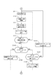
次に動作を説明する。図2は本発明の操舵制御処理の流れを示すフローチャートである。尚、本制御は、車両のイグニッションスイッチなどにより起動される。
【0015】
S1では、通常処理モードに設定する。この処理モードでは誤動作しているアクチュエータを判定するための処理は実行せずに、偏差付加部13において偏差を付加しないでアクチュエータへ指令値を出力する処理を実行する。
【0016】
S2では、操作角センサ3において検出される車両の運転者の指令舵角を制御装置10に入力する。
【0017】
S3では、入力された指令舵角に応じてアクチュエータへの制御出力を算出する。例えば、アクチュエータに直流誘導モータを用いた場合、印加される電流値に比例したトルクが出力される。このときの比例係数をトルク定数という。従って、指令舵角に対して算出される転舵角の目標値に舵取り車輪4の転舵角を一致させるために必要な操作トルクを算出し、この操作トルクを出力するための電流値を出力する。このとき、2つ以上の複数のアクチュエータが1つの操作部材であるステアリングギア8に接続されているが、各アクチュエータへの出力を個別に演算するのではなく、複数のアクチュエータを1つのアクチュエータと見なして出力値の演算を行う。前出の直流誘導モータの例に従えば、各モータのステアリングギア8との接続部分のギア比とトルク定数の積を算出し、それらの和を定数として1つの出力値を演算する。
【0018】
S4では、S3で算出された1つの出力値を複数のアクチュエータに分配する。ここでは、出力値を等分するようにしても良いし、アクチュエータごとのステアリングギア8との接続部分のギア比とトルク定数の積を考慮して、各アクチュエータのステアリングギア8への伝達トルクが等しくなるように分配しても良い。また、各アクチュエータのステアリングギア8への伝達トルクが一定の比率になるように分配しても良い。
【0019】
S5では、制御装置10内のフィードバック演算器11により、舵取り車輪4の転舵角を転舵角センサ9から読み込んで目標転舵角との差を算出し、この差に応じたフィードバック量を演算して制御装置10の出力に付加する。ここでのフィードバック演算器11と他の制御ブロックとの関係を図3に示す。フィードバック演算器11は、内部に制御対象であるアクチュエータと操作部材を制御モデル化したブロックを持ち、制御対象の出力結果から制御対象の状態量としてアクチュエータごとの出力を推定する操作力推定部11bと、推定された操作力と実際に制御対象に出力している制御出力値(指令舵角に応じて出力されるフィードフォワード演算器18の出力)とを比較して、システムに入力された外乱を推定する外乱推定部11aと、その差分である外乱を除去するような調整値を制御出力に付加する外乱補償部11cから構成されている。このフィードバック演算器11からの出力(付加される値)の所定時間(たとえば1分間)の平均値を算出する。
【0020】
S6では、S5で算出されたフィードバック量の平均値が0より所定値以上離れているか判断する。フィードバック演算器11内の制御モデルが実際の制御対象と一致していれば、フィードバック演算器11による調整値は横風や道路の傾きなど道路環境の外乱による制御の乱れを補償するように機能する。したがって、車両が通常の条件下で道路を走行している場合は、確率的に左右どちらか一方に偏ったり、長時間継続して道路環境の外乱が発生することは考えにくい。そこで、フィードバック量の平均値が0より所定値以上離れていれば、制御システムに何らかの誤動作が生じていると判断できる。フィードバック量の平均値が0より所定値以上離れていなければS2に戻って処理を継続し、所定値以上離れていればS7に進む。
【0021】
S7では、操舵角および/または操舵角速度が所定値以内であるか判断し、所定値以内でなければS2に戻って処理を継続し、所定値以内であればS8に進む。
【0022】
S8では、誤動作アクチュエータ判定モードに設定する。この処理モードでは誤動作しているアクチュエータを判定するための処理を実行するために、偏差付加部13において偏差を付加してアクチュエータへ指令値を出力する処理を実行する。
【0023】
S9、S10では、各々S2、S3と同じ処理を実行する。
【0024】
S11では、S4と同じ処理を実行し、さらに各アクチュエータへの出力に意図的に偏差を付加する。例えば、3つのアクチュエータが接続されている場合は、アクチュエータAには+10%、アクチュエータBには+20%、アクチュエータCには+40%の偏差を付加する。ただし、この偏差量を一度に付加するのではなく、例えば偏差量の10%ずつを10回の処理で付加するなど、徐々に付加していく。
【0025】
S12では、S5と同様にフィードバック量を演算するが、このときフィードバック演算器に入力されるフィードフォワード出力には、S11で偏差を付加する前の値を用いる。
【0026】
S13では、S11で付加した偏差量がすべて付加されているか判定し、付加されていなければS9に戻り、付加されていればS14に進む。
【0027】
S14では、システム調整器17により付加した偏差と、偏差付加に応じたフィードバック量の変化を比較し、誤動作しているアクチュエータを判定する。前出の偏差付加の例に従えば、アクチュエータAが誤動作していればフィードバック量は60%、アクチュエータBが誤動作していればフィードバック量は50%、アクチュエータCが誤動作していればフィードバック量は30%、アクチュエータが誤動作していなければフィードバック量は70%の偏差と等しくなる。誤動作アクチュエータが判定されればS15に進み、誤動作アクチュエータが判定されなければS16に進む。
【0028】
S15では、誤動作アクチュエータと判定されたアクチュエータを以後使用しないように、制御装置10のパラメータを誤動作アクチュエータを除いたシステムのパラメータに変更するとともに、出力分配器12では誤動作アクチュエータに出力を分配しないようにする。さらに、システム構成図には明記していないが、誤動作アクチュエータへ供給される電源を遮断し、誤動作アクチュエータの影響がシステムに及ばないようにする。これにより無駄な電力消費を防止することができる。
【0029】
S16では、フィードバック平均値が0になるようにフィードバック演算器11のパラメータを調整する。S15およびS16の処理が終了後、S1に戻り再び通常処理モードに設定する。以上の流れによって、本発明の動作が実行される。
【0030】
以上説明したように、第1実施例の多重系車両操舵装置においては、制御装置10は、複数のアクチュエータを統合された1つのアクチュエータとみなして制御出力値を演算するとともに、センサ出力よりアクチュエータから発生している操作力を推定して、推定値と、実際にアクチュエータに出力している制御出力値とを比較することにより外部からシステムに加えられる外乱を推定して、外乱が相殺されるように制御出力を調整するフィードバック演算器を有する構成なので、複数のアクチュエータの少なくとも1つ以上に誤動作が発生しても、アクチュエータ間に拮抗を生じさせることなく安定した車両の操向を実現することができる。
【0031】
また、出力分配器12は、制御装置10から制御出力を2つ以上のアクチュエータに分配する際、分配した出力値に意図的に偏差を加えることができる偏差付加部13を有し、フィードバック演算器の調整する調整値が所定の範囲を超える動作をした場合は、2つ以上のアクチュエータに各々異なる偏差を付加し、偏差付加後にフィードバック演算器で演算される調整値と、偏差付加部13で付加された偏差とを比較する構成なので、誤動作の発生しているアクチュエータを判定することができる。また、フィードバック演算器の調整値により、車両の操向制御が正常な状態のままで誤動作の発生しているアクチュエータを判定することができる。
【0032】
また、偏差付加部13において、偏差を付加する場合に、偏差量を必要な値まで徐々に増大する構成なので、フィードバック演算器の調整値によって車両の操向制御が正常な状態のままで誤動作の発生しているアクチュエータを特定することができる。
【0033】
また、フィードバック演算器11の調整する調整値の所定時間(例えば1分間)間隔毎の平均値が、0から所定値以上離れた値となった場合に、誤動作の発生しているアクチュエータを特定する処理を実行する構成なので、実際にシステムに加えられた外乱の影響を排除して誤動作の発生しているアクチュエータを特定する処理を実行することができる。
【0034】
また、偏差付加部13において偏差を付加する操作を、操作部材(ナックルアーム,タイロッド,ステアリングギア等)によって制御される車両の操舵角が直進状態を挟む所定の範囲内であるか、車両の操舵角速度が0を挟む所定の範囲内であるか、操作部材によって制御される車両の操舵角が直進状態を挟む所定の範囲内で、かつ、車両の操舵角速度が0を挟む所定の範囲内のときに実行する構成なので、例えばフィードバック演算器11の調整値が時間的な応答遅れを生じて車両の操向制御に影響を及ぼすようなことがあっても、車両挙動への影響を低く抑えることができる。
【0035】
また、偏差付加部13において偏差付加後に、フィードバック演算器で演算される調整値と偏差付加部13で付加された偏差とを比較することにより、誤動作の発生しているアクチュエータが特定された場合は、誤動作の発生しているアクチュエータをシステムから除外し、誤動作の発生しているアクチュエータを特定できなかった場合は、フィードバック演算器11の演算パラメータを調整する構成なので、故障部位を除外するだけでなく、制御システムのパラメータ調整も実行することができる。尚、誤動作の発生しているアクチュエータをシステムから除外する際、電源供給を遮断することで、無駄な電力消費を防止することができる。
【0036】
(第2実施例)
続いて、本発明の第2実施例を説明する。これは、システム構成、処理の流れは第1実施例と同様の処理の説明は省略し、図4を用いて異なる部分のみ説明する。
【0037】
S110では、偏差を付加する際に、複数のアクチュエータのうち1つのアクチュエータのみに偏差を付加する。
【0038】
S140では、誤動作アクチュエータと判定されなかった場合はS141に進み、すべてのアクチュエータが調査されていなければS142に進んで別のアクチュエータを調査するように設定してS9に戻る。すべてのアクチュエータが調査されていればS143に進んで図2のS16と同じ処理を実行する。S140において誤動作アクチュエータと判定された場合はS144に進み、図2のS15と同じ処理を実行する。以上の流れによって、本発明の動作が実行される。
【0039】
以上説明したように、第2実施例にあっては、フィードバック演算器11の調整する調整値が所定の範囲を超える動作をした場合は、偏差付加部13において2つ以上のアクチュエータの1つに偏差を付加し、偏差付加後に、フィードバック演算器11で演算される調整値と偏差付加部13で付加された偏差とを比較することにより、偏差を付加したアクチュエータに誤動作が発生しているかを判定し、上記の操作を他のアクチュエータにも順次実施する構成なので、誤動作の発生しているアクチュエータを判定することができる。また、フィードバック演算器11の調整値により車両の操向制御が正常な状態のままで誤動作の発生しているアクチュエータを判定することができる。
【図面の簡単な説明】
【図1】第1実施例における多重系車両操舵装置の全体システムを表すシステム図である。
【図2】第1実施例における操舵制御の制御内容を表すフローチャートである。
【図3】第1実施例における制御装置の制御構成を表すブロック図である。
【図4】第2実施例における操舵制御の制御内容を表すフローチャートである。
【符号の説明】
1 ステアリングホイール
2 反力アクチュエータ
3 操作角センサ
4 舵取り車輪
5 ナックルアーム
6 タイロッド
7 ステアリングロッド
8 ステアリングギヤ
9 転舵角センサ
10 制御装置
11 フィードバック演算器
11a 外乱推定部
11b 操作力推定部
11c 外乱補償部
12 出力分配器
13 偏差付加部
14,15,16 転舵アクチュエータ
17 システム調整器
18 フィードフォワード演算器[0001]
BACKGROUND OF THE INVENTION
The present invention relates to a multi-system vehicle steering apparatus having a main steering drive system for driving a steering mechanism of a vehicle, and a sub-steering drive system for driving the steering mechanism instead when the main steering drive system fails. .
[0002]
[Prior art]
Conventionally, for example, a technique described in Patent Document 1 is known as a multi-system vehicle steering apparatus. In this technique, a steering mechanism is driven by a dual-system steering drive device including a main steering drive system and a sub-steer drive system. The main steering actuator and the auxiliary steering actuator are mechanically linked via a link mechanism having play and are always driven. At this time, a mutual interference detection mechanism is provided to detect the presence or absence of interference between the main steering drive system and the auxiliary steering drive system. Then, the main control unit and the sub control unit bring down their own steering drive system when an abnormality occurs in their own steering drive system. The main control unit and the sub control unit forcibly stop the other steering drive system when the mutual interference detection mechanism detects the mutual interference when the steering drive system is normal. As a result, a reliable fail safe is realized while preventing a decrease in the output of the steering drive system.
[0003]
[Patent Document 1]
JP 2002-37112 A (see page 3)
[0004]
[Problems to be solved by the invention]
However, since the main steering actuator and the sub-steering actuator are mechanically linked by a link mechanism having play, there is a problem in that an actuator operation that does not affect the control occurs and power consumption is wasted. In addition, if an abnormality has occurred in the self-steering drive system, but the abnormality could not be detected, the system that is operating normally due to mutual interference is down and the system in which the abnormality has occurred There was a risk of continuing control.
[0005]
In view of the above-described problems, the present invention provides a multi-vehicle steering apparatus capable of achieving stable vehicle steering without causing mutual interference in a multi-vehicle steering apparatus such as a main steering driving system and a sub steering driving system. For the purpose.
[0006]
[Means for Solving the Problems]
In order to achieve the above object, the present invention detects an operation means for steering a vehicle, a plurality of actuators attached to the operation means and generating an operation force, and a physical quantity related to the control of the operation means. Based on the output of the sensor, a control means for outputting a signal for controlling the running of the vehicle to the plurality of actuators, and a signal output from the control means to the plurality of actuators. In the multiplex system vehicle steering apparatus provided with output distribution means for distributing, an operating force estimation unit that estimates the operating force generated from the actuator based on the sensor output to the control means, and actually Disturbance estimation that estimates the disturbance applied to the system from the outside by comparing the control output value output to the actuator with the estimated operating force value And a feedback computing unit having a disturbance compensation unit that adjusts the control output so that the estimated disturbance is canceled, and the control means regards the plurality of actuators as one integrated actuator, and outputs a control output. The output distributing unit has a deviation adding unit that intentionally adds a deviation to the distributed output value when the control output from the control unit is distributed to the plurality of actuators. A controller adds a deviation to at least one of the plurality of actuators when the adjustment value adjusted by the feedback calculator exceeds a predetermined range; and the control means adds the deviation after adding the deviation. By comparing the adjustment value calculated by the detector with the deviation added by the deviation adding unit, the actuator that has malfunctioned can be determined. And wherein the Rukoto.
[0007]
【The invention's effect】
In the present invention, the control device regards a plurality of actuators as one integrated actuator, calculates a control output value, estimates the operating force generated from the actuator from the sensor output, and Since a disturbance applied to the system from the outside is estimated by comparing the output control output value with the estimated operating force, and a feedback calculator that adjusts the control output so that the disturbance is canceled, 2 Even if malfunction occurs in at least one of the one or more actuators, the steering of the vehicle can be realized stably without causing antagonism between the actuators.
[0008]
DETAILED DESCRIPTION OF THE INVENTION
The present invention will be described below with reference to the drawings.
(First embodiment)
FIG. 1 is a system configuration diagram of the present invention. Reference numeral 1 denotes a steering wheel that transmits the operation of the driver of the vehicle, 2 denotes a reaction force actuator that generates an operation reaction force on the steering wheel, and 3 denotes an operation angle sensor for detecting an operation amount by which the steering wheel is operated. Further, 4 is a steering wheel for steering the vehicle, and 5, 6 and 7 are knuckle arms, tie rods, and steering rods for transmitting the driving force to the wheels. Reference numeral 8 denotes a steering gear that transmits a force in the lateral direction of the vehicle to steer the vehicle, and 9 denotes a turning angle sensor that detects a turning angle of the steering wheel.
[0009]
[0010]
An
[0011]
[0012]
[0013]
With these configurations, a so-called steer-by-wire function that can arbitrarily change the characteristics of the turning angle in response to a driver's operation input is realized.
[0014]
Next, the operation will be described. FIG. 2 is a flowchart showing the flow of the steering control process of the present invention. This control is activated by an ignition switch of the vehicle.
[0015]
In S1, the normal processing mode is set. In this processing mode, the process for determining the malfunctioning actuator is not executed, and the
[0016]
In S <b> 2, the commanded steering angle of the vehicle driver detected by the
[0017]
In S3, a control output to the actuator is calculated according to the input command steering angle. For example, when a direct current induction motor is used as the actuator, a torque proportional to the applied current value is output. The proportionality coefficient at this time is called a torque constant. Therefore, the operation torque necessary to make the steering angle of the steering wheel 4 coincide with the target value of the steering angle calculated with respect to the command steering angle, and the current value for outputting this operation torque is output. To do. At this time, two or more plural actuators are connected to the steering gear 8 which is one operation member. However, instead of individually calculating the output to each actuator, the plural actuators are regarded as one actuator. To calculate the output value. According to the above-described example of the DC induction motor, the product of the gear ratio and the torque constant of the connection portion of each motor with the steering gear 8 is calculated, and one output value is calculated using the sum as a constant.
[0018]
In S4, one output value calculated in S3 is distributed to a plurality of actuators. Here, the output value may be equally divided, and the transmission torque to the steering gear 8 of each actuator is determined in consideration of the product of the gear ratio and torque constant of the connection portion of each actuator with the steering gear 8. You may distribute so that it may become equal. Alternatively, the torque transmitted to the steering gear 8 of each actuator may be distributed at a constant ratio.
[0019]
In S5, the
[0020]
In S6, it is determined whether the average value of the feedback amount calculated in S5 is more than a predetermined value from 0. If the control model in the
[0021]
In S7, it is determined whether the steering angle and / or the steering angular velocity is within a predetermined value. If not within the predetermined value, the process returns to S2 to continue the process, and if within the predetermined value, the process proceeds to S8.
[0022]
In S8, the malfunction actuator determination mode is set. In this processing mode, in order to execute the process for determining the malfunctioning actuator, the
[0023]
In S9 and S10, the same processing as that in S2 and S3 is executed.
[0024]
In S11, the same processing as S4 is executed, and a deviation is intentionally added to the output to each actuator. For example, when three actuators are connected, a deviation of + 10% is added to the actuator A, + 20% is added to the actuator B, and + 40% is added to the actuator C. However, this deviation amount is not added at once, but is gradually added, for example, by adding 10% of the deviation amount by 10 processes.
[0025]
In S12, the feedback amount is calculated in the same manner as in S5. At this time, the value before adding the deviation in S11 is used for the feedforward output input to the feedback calculator.
[0026]
In S13, it is determined whether or not all the deviations added in S11 are added. If not added, the process returns to S9, and if added, the process proceeds to S14.
[0027]
In S14, the deviation added by the
[0028]
In S15, the parameter of the
[0029]
In S16, the parameters of the
[0030]
As described above, in the multiplex system vehicle steering apparatus according to the first embodiment, the
[0031]
The
[0032]
In addition, when adding a deviation, the
[0033]
Further, when the average value of the adjustment values adjusted by the
[0034]
Further, an operation for adding the deviation in the
[0035]
When the
[0036]
(Second embodiment)
Next, a second embodiment of the present invention will be described. The description of the system configuration and the flow of processing is the same as that of the first embodiment, and only different portions will be described with reference to FIG.
[0037]
In S110, when adding the deviation, the deviation is added to only one of the plurality of actuators.
[0038]
In S140, if it is not determined that the actuator is malfunctioning, the process proceeds to S141. If all the actuators have not been investigated, the process proceeds to S142 to set another actuator to be investigated, and the process returns to S9. If all the actuators have been investigated, the process proceeds to S143, and the same process as S16 in FIG. 2 is executed. If it is determined in S140 that the actuator is malfunctioning, the process proceeds to S144, and the same process as S15 in FIG. 2 is executed. The operation of the present invention is executed by the above flow.
[0039]
As described above, in the second embodiment, when the adjustment value adjusted by the
[Brief description of the drawings]
FIG. 1 is a system diagram showing an overall system of a multiple vehicle steering apparatus in a first embodiment.
FIG. 2 is a flowchart showing the details of steering control in the first embodiment.
FIG. 3 is a block diagram illustrating a control configuration of the control device according to the first embodiment.
FIG. 4 is a flowchart showing the details of steering control in the second embodiment.
[Explanation of symbols]
DESCRIPTION OF SYMBOLS 1 Steering wheel 2
Claims (9)
該操作手段に取り付けられ、操作力を発生させる複数のアクチュエータと、
前記操作手段の制御に関連した物理量を検出するセンサと、
該センサの出力に基づいて、前記複数のアクチュエータに対し、車両の走行を制御するための信号を出力する制御手段と、
該制御手段から出力された信号を、前記複数のアクチュエータに分配するための出力分配手段と、
を備えた多重系車両操舵装置において、
前記制御手段に、前記センサ出力に基づいて前記アクチュエータから発生している操作力を推定する操作力推定部と、実際にアクチュエータに出力している制御出力値と前記操作力推定値を比較することにより外部からシステムに加えられる外乱を推定する外乱推定部と、該推定された外乱が相殺されるように制御出力を調整する外乱補償部を有するフィードバック演算器を設け、
前記制御手段は、前記複数のアクチュエータを統合された1つのアクチュエータとみなして制御出力値を演算し、
前記出力分配手段は、前記制御手段からの制御出力を前記複数のアクチュエータに分配する際に、分配した出力値に意図的に偏差を加える偏差付加部を有し、
該偏差付加部は、前記フィードバック演算器の調整する調整値が所定の範囲を超える動作をした場合は、前記複数のアクチュエータの少なくとも1つに偏差を付加し、
前記制御手段は、偏差付加後に、前記フィードバック演算器で演算される調整値と前記偏差付加部で付加された偏差とを比較することにより、誤動作の発生しているアクチュエータを判定することを特徴とする多重系車両操舵装置。Operating means for steering the vehicle;
A plurality of actuators attached to the operating means and generating an operating force;
A sensor for detecting a physical quantity related to control of the operating means;
Control means for outputting a signal for controlling the running of the vehicle to the plurality of actuators based on the output of the sensor;
Output distribution means for distributing a signal output from the control means to the plurality of actuators;
In a multi-system vehicle steering apparatus comprising:
The control means estimates the operation force generated from the actuator based on the sensor output, and compares the operation output estimated value with the control output value actually output to the actuator. A feedback operation unit having a disturbance estimation unit that estimates a disturbance applied to the system from the outside and a disturbance compensation unit that adjusts a control output so that the estimated disturbance is canceled,
The control means regards the plurality of actuators as one integrated actuator, calculates a control output value ,
The output distribution unit has a deviation adding unit that intentionally adds a deviation to the distributed output value when distributing the control output from the control unit to the plurality of actuators.
The deviation adding unit adds a deviation to at least one of the plurality of actuators when the adjustment value to be adjusted by the feedback calculator exceeds a predetermined range.
The control means, after adding a deviation, compares the adjustment value calculated by the feedback calculator and the deviation added by the deviation adding unit to determine an actuator in which a malfunction occurs. Multi-system vehicle steering device.
前記偏差付加部は、前記フィードバック演算器の調整する調整値が所定の範囲を超える動作をした場合は、前記複数のアクチュエータに各々異なる偏差を付加することを特徴とする多重系車両操舵装置。The multi-system vehicle steering apparatus according to claim 1,
The deviation adding unit, when the adjustment value for adjusting the feedback arithmetic unit has an operation that exceeds a predetermined range, multi-system vehicle steering apparatus according to claim-added to Rukoto different respective deviation of the plurality of actuators .
前記偏差付加部は、前記フィードバック演算器の調整する調整値が所定の範囲を超える動作をした場合は、前記偏差付加部において前記複数のアクチュエータの1つに偏差を付加し、
前記制御手段は、偏差付加後に、前記フィードバック演算器で演算される調整値と前記偏差付加部で付加された偏差とを比較することにより、偏差を付加したアクチュエータに誤動作が発生しているかを判定し、上記操作を他の前記アクチュエータにも順次実施することにより、誤動作の発生しているアクチュエータを特定することを特徴とする多重系車両操舵装置。The multi-system vehicle steering apparatus according to claim 1,
The deviation adding unit adds a deviation to one of the plurality of actuators in the deviation adding unit when the adjustment value to be adjusted by the feedback calculator exceeds the predetermined range.
After the deviation is added , the control means compares the adjustment value calculated by the feedback calculator with the deviation added by the deviation adding unit to determine whether a malfunction has occurred in the actuator to which the deviation is added. Then, a multi-system vehicle steering apparatus characterized by identifying the actuator in which the malfunction occurs by sequentially performing the above-described operation on the other actuators.
前記偏差付加部において偏差を付加する際に、偏差量を必要な値まで徐々に増大させることを特徴とする多重系車両操舵装置。In the multiplex system vehicle steering device according to any one of claims 1 to 3,
A multi-system vehicle steering apparatus characterized in that, when adding a deviation in the deviation adding section, the deviation amount is gradually increased to a required value.
前記制御手段は、前記フィードバック演算器の調整する調整値の所定時間間隔毎に平均値が、0から所定値以上離れた値になったときは、誤動作の発生しているアクチュエータを特定する処理を実行することを特徴とする多重系車両操舵装置。In the multiplex system vehicle steering device according to any one of claims 1 to 4,
When the average value of the adjustment value adjusted by the feedback calculator becomes a value that is more than a predetermined value away from 0 , the control means performs a process of identifying an actuator in which a malfunction occurs. A multi-system vehicle steering apparatus characterized by being executed.
前記偏差付加部において偏差を付加する操作を、前記操作部材によって制御される車両の操舵角が、直進状態を挟む所定の範囲内の時に実行することを特徴とする多重系車両操舵装置。In the multiplex system vehicle steering device according to any one of claims 1 to 5,
An operation for adding a deviation in the deviation adding unit is executed when a steering angle of a vehicle controlled by the operating member is within a predetermined range across a straight traveling state.
前記偏差付加部において偏差を付加する操作を、前記操作部材によって制御される車両の操舵角速度が、0を挟む所定の範囲内の時に実行することを特徴とする多重系車両操舵装置。In the multiplex system vehicle steering device according to any one of claims 1 to 5,
An operation for adding a deviation in the deviation adding unit is executed when a steering angular velocity of the vehicle controlled by the operating member is within a predetermined range with 0 being sandwiched therebetween.
前記偏差付加部において偏差を付加する操作を、前記操作部材によって制御される車両の操舵角が直進状態を挟む所定の範囲内で、かつ、車両の操舵角速度が0を挟む所定の範囲内の時に実行することを特徴とする多重系車両操舵装置。In the multiplex system vehicle steering device according to any one of claims 1 to 5,
The operation of adding a deviation in the deviation adding unit is performed when the steering angle of the vehicle controlled by the operating member is within a predetermined range that sandwiches the straight traveling state and the steering angular velocity of the vehicle is within a predetermined range that sandwiches 0. A multi-system vehicle steering apparatus characterized by being executed.
前記制御手段は、前記偏差付加部において偏差付加後に、前記フィードバック演算器で演算される調整値と前記偏差付加部で付加された偏差とを比較することにより、誤動作の発生しているアクチュエータを特定した場合は、該誤動作の発生しているアクチュエータをシステムから除外し、誤動作の発生しているアクチュエータを特定できなかった場合は、前記フィードバック演算器の演算パラメータを調整することを特徴とする多重系車両操舵装置。In the multiplex system vehicle steering apparatus according to any one of claims 1 to 8,
The control means identifies an actuator in which a malfunction has occurred by comparing the adjustment value calculated by the feedback calculator and the deviation added by the deviation adding unit after adding the deviation by the deviation adding unit. The malfunctioning actuator is excluded from the system, and if the malfunctioning actuator cannot be specified, the computing parameter of the feedback computing unit is adjusted. Vehicle steering device.
Priority Applications (3)
| Application Number | Priority Date | Filing Date | Title |
|---|---|---|---|
| JP2002365999A JP4140372B2 (en) | 2002-12-18 | 2002-12-18 | Multi-system vehicle steering system |
| US10/717,709 US7004280B2 (en) | 2002-12-18 | 2003-11-21 | Multiplex power steering device |
| DE10358907A DE10358907B4 (en) | 2002-12-18 | 2003-12-16 | Multiple power-assisted steering device |
Applications Claiming Priority (1)
| Application Number | Priority Date | Filing Date | Title |
|---|---|---|---|
| JP2002365999A JP4140372B2 (en) | 2002-12-18 | 2002-12-18 | Multi-system vehicle steering system |
Publications (2)
| Publication Number | Publication Date |
|---|---|
| JP2004196085A JP2004196085A (en) | 2004-07-15 |
| JP4140372B2 true JP4140372B2 (en) | 2008-08-27 |
Family
ID=32588292
Family Applications (1)
| Application Number | Title | Priority Date | Filing Date |
|---|---|---|---|
| JP2002365999A Expired - Fee Related JP4140372B2 (en) | 2002-12-18 | 2002-12-18 | Multi-system vehicle steering system |
Country Status (3)
| Country | Link |
|---|---|
| US (1) | US7004280B2 (en) |
| JP (1) | JP4140372B2 (en) |
| DE (1) | DE10358907B4 (en) |
Families Citing this family (18)
| Publication number | Priority date | Publication date | Assignee | Title |
|---|---|---|---|---|
| JP4608948B2 (en) * | 2004-05-27 | 2011-01-12 | 日産自動車株式会社 | Vehicle steering system |
| JP4622448B2 (en) * | 2004-10-19 | 2011-02-02 | 株式会社ジェイテクト | Vehicle steering system |
| JP4556657B2 (en) * | 2004-12-14 | 2010-10-06 | 日産自動車株式会社 | Vehicle steering control device |
| US7664584B2 (en) * | 2005-03-01 | 2010-02-16 | Nissan Motor Co., Ltd. | Steering control system |
| JP4613668B2 (en) * | 2005-04-01 | 2011-01-19 | 日産自動車株式会社 | Vehicle behavior control apparatus and vehicle behavior control method |
| US20060278466A1 (en) * | 2005-06-13 | 2006-12-14 | Bo Cheng | Electric power steering systems |
| ATE540851T1 (en) * | 2006-11-10 | 2012-01-15 | Jtekt Corp | ELECTRIC POWER STEERING DEVICE |
| JP4872614B2 (en) * | 2006-11-13 | 2012-02-08 | 株式会社ジェイテクト | Electric power steering device |
| JP4941723B2 (en) * | 2006-12-28 | 2012-05-30 | 株式会社ジェイテクト | Vehicle steering system |
| EP2402234B1 (en) * | 2010-07-01 | 2013-08-28 | Steering Solutions IP Holding Corporation | Dynamic system compensator for actively controlled power steering systems |
| KR101405603B1 (en) * | 2012-03-12 | 2014-06-10 | 주식회사 만도 | Electric Power Steering Apparatus for Vehicle |
| US8725354B2 (en) * | 2012-05-21 | 2014-05-13 | GM Global Technology Operations LLC | Electric power steering systems and methods |
| KR102619851B1 (en) | 2015-08-14 | 2024-01-04 | 크라운 이큅먼트 코포레이션 | Diagnostic supervisor to determine if the traction system is in a malfunctioning condition. |
| EP3334637B1 (en) | 2015-08-14 | 2020-03-18 | Crown Equipment Corporation | Model based diagnostics based on steering model |
| KR101734718B1 (en) * | 2015-12-14 | 2017-05-11 | 현대자동차주식회사 | Disturbance compensating system for motor |
| US10414288B2 (en) | 2017-01-13 | 2019-09-17 | Crown Equipment Corporation | Traction speed recovery based on steer wheel dynamic |
| KR102442228B1 (en) | 2017-01-13 | 2022-09-13 | 크라운 이큅먼트 코포레이션 | Suppression of high-speed front tiller sensitivity |
| CA3099415A1 (en) * | 2019-12-20 | 2021-02-05 | Bombardier Transportation Gmbh | Steering system for an autonomous vehicle |
Family Cites Families (12)
| Publication number | Priority date | Publication date | Assignee | Title |
|---|---|---|---|---|
| US5739811A (en) * | 1993-07-16 | 1998-04-14 | Immersion Human Interface Corporation | Method and apparatus for controlling human-computer interface systems providing force feedback |
| JP3019254B2 (en) * | 1997-06-26 | 2000-03-13 | 本田技研工業株式会社 | Electric power steering device |
| US6370459B1 (en) * | 1998-07-21 | 2002-04-09 | Techco Corporation | Feedback and servo control for electric power steering systems |
| DE19841101C2 (en) | 1998-09-09 | 2000-06-21 | Daimler Chrysler Ag | Steering system for non-track-bound motor vehicles |
| US6923288B2 (en) * | 2000-04-03 | 2005-08-02 | Trw Inc. | Electric steering apparatus |
| JP2002037112A (en) | 2000-07-25 | 2002-02-06 | Koyo Seiko Co Ltd | Steering wheel for vehicle |
| GB2368053A (en) * | 2000-10-20 | 2002-04-24 | Nsk Ltd | Electric power steering control |
| DE10052343A1 (en) * | 2000-10-21 | 2002-07-11 | Bosch Gmbh Robert | Method for controlling a steerby wire steering system |
| JP4178217B2 (en) * | 2002-03-27 | 2008-11-12 | 株式会社ジェイテクト | Vehicle steering system |
| US7212896B2 (en) * | 2002-05-29 | 2007-05-01 | Ford Global Technologies, Llc | Vehicle control |
| US7014008B2 (en) * | 2002-06-27 | 2006-03-21 | Honda Giken Kogyo Kabushiki Kaisha | Steering system for vehicle |
| JP3867682B2 (en) * | 2003-05-29 | 2007-01-10 | 日産自動車株式会社 | Vehicle steering system |
-
2002
- 2002-12-18 JP JP2002365999A patent/JP4140372B2/en not_active Expired - Fee Related
-
2003
- 2003-11-21 US US10/717,709 patent/US7004280B2/en not_active Expired - Lifetime
- 2003-12-16 DE DE10358907A patent/DE10358907B4/en not_active Expired - Fee Related
Also Published As
| Publication number | Publication date |
|---|---|
| JP2004196085A (en) | 2004-07-15 |
| DE10358907A1 (en) | 2004-07-15 |
| US7004280B2 (en) | 2006-02-28 |
| DE10358907B4 (en) | 2011-01-20 |
| US20040118629A1 (en) | 2004-06-24 |
Similar Documents
| Publication | Publication Date | Title |
|---|---|---|
| JP4140372B2 (en) | Multi-system vehicle steering system | |
| EP2492168B1 (en) | Electric power steering device for vehicle | |
| US9434408B2 (en) | Vehicle control device | |
| US7753162B2 (en) | Vehicle steering apparatus and vehicle steering method | |
| JP5327333B2 (en) | Vehicle travel control device | |
| US20140005894A1 (en) | Electric power steering apparatus | |
| JP2009248660A (en) | Electric steering device for vehicle | |
| CN113557188B (en) | Method for controlling a steer-by-wire steering system and steering system | |
| US10414429B2 (en) | Steering control system | |
| US20090030573A1 (en) | Vehicle steering apparatus | |
| JP4821185B2 (en) | Vehicle steering control device | |
| EP1321347A2 (en) | Electric power steering apparatus | |
| KR20180115374A (en) | Control apparatus and method for rear wheel steering system | |
| JP4211518B2 (en) | Electric power steering control device | |
| JP2016172471A (en) | Rear wheel steering control device | |
| JP2006282067A (en) | Steering control device for vehicle | |
| JP4969368B2 (en) | Control method of electric steering device | |
| JP2006168481A (en) | Vehicle steering controller and steered angle control method | |
| JP4556657B2 (en) | Vehicle steering control device | |
| US11084527B2 (en) | Method for supervising the operation of a power steering system | |
| JP5966684B2 (en) | Vehicle steering control device | |
| CN115916629A (en) | Automatic steering control device and automatic steering control system for vehicle | |
| JP5092763B2 (en) | Electric power steering device | |
| JP4692087B2 (en) | Vehicle steering system | |
| JP2008221869A (en) | Electric power steering device |
Legal Events
| Date | Code | Title | Description |
|---|---|---|---|
| A621 | Written request for application examination |
Free format text: JAPANESE INTERMEDIATE CODE: A621 Effective date: 20051026 |
|
| RD04 | Notification of resignation of power of attorney |
Free format text: JAPANESE INTERMEDIATE CODE: A7424 Effective date: 20051117 |
|
| A977 | Report on retrieval |
Free format text: JAPANESE INTERMEDIATE CODE: A971007 Effective date: 20080321 |
|
| A131 | Notification of reasons for refusal |
Free format text: JAPANESE INTERMEDIATE CODE: A131 Effective date: 20080401 |
|
| A521 | Written amendment |
Free format text: JAPANESE INTERMEDIATE CODE: A523 Effective date: 20080425 |
|
| TRDD | Decision of grant or rejection written | ||
| A01 | Written decision to grant a patent or to grant a registration (utility model) |
Free format text: JAPANESE INTERMEDIATE CODE: A01 Effective date: 20080520 |
|
| A01 | Written decision to grant a patent or to grant a registration (utility model) |
Free format text: JAPANESE INTERMEDIATE CODE: A01 |
|
| A61 | First payment of annual fees (during grant procedure) |
Free format text: JAPANESE INTERMEDIATE CODE: A61 Effective date: 20080602 |
|
| FPAY | Renewal fee payment (event date is renewal date of database) |
Free format text: PAYMENT UNTIL: 20110620 Year of fee payment: 3 |
|
| R150 | Certificate of patent or registration of utility model |
Free format text: JAPANESE INTERMEDIATE CODE: R150 |
|
| FPAY | Renewal fee payment (event date is renewal date of database) |
Free format text: PAYMENT UNTIL: 20120620 Year of fee payment: 4 |
|
| FPAY | Renewal fee payment (event date is renewal date of database) |
Free format text: PAYMENT UNTIL: 20120620 Year of fee payment: 4 |
|
| FPAY | Renewal fee payment (event date is renewal date of database) |
Free format text: PAYMENT UNTIL: 20130620 Year of fee payment: 5 |
|
| LAPS | Cancellation because of no payment of annual fees |