JP4140218B2 - Inspection method and apparatus for laser welds - Google Patents
Inspection method and apparatus for laser welds Download PDFInfo
- Publication number
- JP4140218B2 JP4140218B2 JP2001258658A JP2001258658A JP4140218B2 JP 4140218 B2 JP4140218 B2 JP 4140218B2 JP 2001258658 A JP2001258658 A JP 2001258658A JP 2001258658 A JP2001258658 A JP 2001258658A JP 4140218 B2 JP4140218 B2 JP 4140218B2
- Authority
- JP
- Japan
- Prior art keywords
- weld
- infrared
- laser
- welding
- image
- Prior art date
- Legal status (The legal status is an assumption and is not a legal conclusion. Google has not performed a legal analysis and makes no representation as to the accuracy of the status listed.)
- Expired - Fee Related
Links
Images


Description
【0001】
【発明の属する技術分野】
本発明は、本発明は被検査物となる2片の金属を重ね合わせ、その一方の面よりレーザーをスポット照射して溶接したレーザー溶接部の溶接不良を、溶接中のモニタリングではなく、溶接後のオフライン検査により検出する方法、特に電子部品リードなどの薄く小さい部材の微細なレーザー溶接部のオフライン検査方法及びその装置に関するものである。
【0002】
【従来の技術】
従来、レーザー溶接部の検査方法としては、特開平5−71932号記載の検査方法のように、スリット状のレーザー光をレーザー溶接部に投影し、当該レーザー光の反射光をレーザー投影方向とは異なる方向からカメラにより観測することによりレーザー溶接部の立体形状を取得する、いわゆる光切断法による立体形状計測を用いた方法がある。
【0003】
また、赤外線カメラを用いたレーザー溶接部の検査方法としては、特開平5−34204号、特開平8−122051号、特開昭52−59046号記載の検査方法のように、レーザー溶接部に加熱を行う過程あるいは加熱後(溶接熱による加熱を含む)の冷却過程において、赤外線カメラによりレーザー溶接部周辺の温度分布を計測することにより溶着部の大きさを測定する方法がある。
【0004】
【発明が解決しようとする課題】
上記従来の立体形状計測による検査方法は、フィラーを用いた突き合わせ溶接やすみ肉溶接などのようにレーザー溶接部が大きく盛り上がる溶接方法においては有効であるが、レーザーによるスポット溶接、特に電子部品のリード部分などの微細な溶接においては溶接に伴う形状の変化が極めて微小であるため精度の高い3次元形状計測方法が必要となり、適用が困難である問題があった。
【0005】
また後者のレーザースポット溶接されたレーザー溶接部に加熱を行う過程あるいは加熱後(溶接熱による加熱を含む)の冷却過程において、温度分布を測定する従来方法においては、レーザー溶接部がある程度の質量(熱容量)を持つ場合には有効な方法であるが、例えば電子部品のリード部分などの極めて薄く質量の小さい部材のレーザー溶接部においては加熱による温度の変化が極めて短時間の間に起こるため、赤外線画像によって正確に温度分布を計測することが困難になる問題があった。
【0006】
本発明は、上記の従来例の問題点に鑑みて発明したものであって、その目的とするところは、溶接後のオフライン検査により、特に電子部品リードなどの薄く小さい部材の微細なレーザー溶接部の検査を精度良く行うことができ、検査の信頼性を向上させることができると共に、良否判定精度を高めることができるレーザー溶接部の検査方法及びその装置を提供することにある。
【0007】
【課題を解決するための手段】
上記課題を解決するために本発明にあっては、被検査物6となる2片の金属を重ね合わせ、その一方の表面にレーザーをスポット照射して溶接したレーザー溶接部1を溶接後に検査する方法において、溶接後雰囲気温度まで冷却したレーザー溶接部1を赤外線カメラ2で撮像し、得られた赤外線画像における輝度の差を被検査物6表面の赤外線放射率の差を表す指標とみなして溶接部領域3を検出する第1の過程と、上記溶接部領域3の形状、上記溶接部領域3内での赤外線画像の輝度値の分布パターン、上記分布パターンをもとに抽出された特徴量の少なくとも1つをもとに溶接の良否を判定する第2の過程とを有することを特徴としており、このように構成することで、赤外線画像の明るさの差(遠赤外線放射率の差)を利用して、レーザー溶接部1と未溶接部の表面性状の違いを検出することができ、簡易な方法でレーザー溶接部1の溶接状態を検査できるようになる。しかも、溶接中のモニタリングではなく、溶接後のオフライン検査により検出するので、特に電子部品リードなどの薄く小さい部材の微細なレーザー溶接部1の検査を精度良く行うことができる。
【0008】
また、少なくともレーザー溶接部1の外周部では熱の影響により表面粗さが大きくなり、赤外線放射率が高くなることを利用して、赤外線画像において明るく見える部分を検出し、当該部分の外周輪郭より内側を溶接部領域3として検出するので、加熱を行うことなくレーザー溶接部1を検出できるようになる。
【0009】
また、検出された溶接部領域3の大きさを基準値と比較することにより溶接の良否を判定するのが好ましく、この場合、簡易な方法で溶接状態の判定ができるようになる。
【0010】
また、検出された溶接部領域3内部の明るく見える外周輪郭の内側に所定の基準値以上の大きさを持つ暗部4があれば良品と判定するのが好ましく、この場合、十分な入熱量が与えられた時は中央部に鏡面状の特徴を生じることを利用して溶接状態の良否を簡易に判定できるようになる。
【0011】
また、上記赤外線カメラ2により検出された溶接部領域3内部で明るく見える外周輪郭の内側に所定の基準値以上の大きさを持つ暗部4があれば良品候補とし、上記良品候補に赤外線を照射し、上記赤外線源5の正反射を捉える方向に第2の赤外線カメラ2aを配置して観測した時、溶接部領域3中央の輝度が高くなる場合に良品と判定するのが好ましく、この場合、能動的に照射した赤外線光の正反射成分を捉える第2の赤外線カメラ2aを付加するだけで、穴あき欠陥と良品を区別できるようになる。
【0012】
また、被検査物6に赤外線を照射する赤外線源5と被検査物6を撮像する赤外線カメラ2を、上記赤外線源5から照射された赤外線の正反射光を赤外線カメラ2で捉えることができるような位置関係になるように配設し、まず赤外線源5を消灯して撮影した赤外線画像を用いて検出された溶接部領域3内部で明るく見える外周輪郭の内側に所定の基準値以上の大きさを持つ暗部4があれば良品候補とし、次に赤外線源5を点灯して観測した時、溶接部領域3中央の輝度が高くなる場合に良品と判定するのが好ましく、この場合、良品候補を抽出するカメラと良否判定を行うカメラを兼用でき、簡易な装置構成にて穴あき欠陥と良品を区別できるようになる。
【0013】
また、良品候補に複数の方向から赤外線を照射していずれかの正反射光を捉えることができれば良品とするのが好ましく、この場合、赤外線源5を複数用いることで、仮りに溶接部領域3中央の鏡面部分の向きが安定しない場合にも穴あき欠陥と良品を正しく区別できるようになる。
【0014】
また、良品候補を斜め方向から赤外線カメラ2で観測するようにし、赤外線画像において溶接部領域3中央に正反射光が捉えられれば良品とし、溶接部領域3中央からずれた位置に正反射光が捉えられれば不良とするのが好ましく、この場合、上下の溶接片8,9の段差が小さい場合にも特別の装置を付加することなく穴あき欠陥と良品を正しく区別できるようになる。
【0015】
また、被検査物6全体を一様に加熱したうえで検査を行うのが好ましく、この場合、被検査物6を一様に加熱するようにすることで赤外線画像のS/N比が改善される。
【0016】
また、正確に溶接状態の良否判定をするために、上記方法で良品候補と判断された被検査物6について、上下の溶接片8,9の間に電圧を与えることによってレーザー溶接部1にジュール熱を発生させた状態で赤外線カメラ2により撮像し、上記溶接部領域3内での輝度値の変化を基準値と比較することによりレーザー溶接部1の良否を判定するのが好ましい。また、上記方法で良品候補と判断された被検査物6について、下側の溶接片9のみを加熱しながら上方より赤外線カメラ2で撮像し、上記溶接部領域3内での輝度値の変化を基準値と比較することによりレーザー溶接部1の良否を判定するのが好ましい。
【0017】
また、下側の溶接片9に通電することにより下側の溶接片9にジュール熱を発生させるのが好ましく、この場合、下側の溶接片9の下側に発熱体を設置できない構造の検査物でも、検査が可能になる。
【0018】
また、下側の溶接片9に高周波磁界を与えて渦電流を発生させることにより加熱するのが好ましく、この場合、下側の溶接片9の下側に発熱体を設置できない構造の検査物でも、検査が可能になる。
【0019】
また、高さ計測装置により上記レーザー溶接部1近辺の少なくとも2点H1,H2の高さ情報を取得し、上記溶接部領域3の輝度値とともに高さ情報を併用して良否判定を行うのが好ましく、この場合、高さ情報を併用することにより穴あき欠陥と良品の区別など画像情報だけでは分かりにくい溶接状態の判定を高い信頼度で行えるようになる。
【0020】
さらに、本発明に係るレーザー溶接部1の検査装置は、赤外線カメラ2(2a)と、赤外線カメラ2(2a)からの出力信号を量子化して画像として記憶する画像取り込み装置10と、上記のいずれかの検査方法により赤外線画像を処理して溶接欠陥検査を行う画像処理装置11とにより構成されているので、赤外線画像の明るさの差(遠赤外線放射率の差)を利用して、レーザー溶接部1と未溶接部の表面性状の違いを画像処理装置11にて検出することができ、簡易な構造でレーザー溶接部1の溶接状態を検査できるようになる。
【0021】
【発明の実施の形態】
以下、本発明を添付図面に示す実施形態に基づいて説明する。
【0022】
図1は、本発明の方法によりレーザー溶接の良否判定をオフラインで行う検査装置の構成を示す図である。この検査装置は、被検査物6となる2片の金属(溶接片8,9)を重ね合わせ、その一方の表面にレーザーをスポット照射して溶接したレーザー溶接部1の溶接状態を溶接後に検査するものであり、詳しくは、検査対象となる溶接片8,9を溶接後雰囲気温度に冷却し、その後レーザー溶接部1付近を赤外線カメラ2により撮像する。ここで、溶接後雰囲気温度まで冷却とは、充分に放熱された状態のことであり、冷却過程ではない。赤外線カメラ2からの撮像データは、画像取り込み装置10に取り込まれる。画像取り込み装置10は、撮像データを画像に変換するための量子化装置14と、画像を格納する画像メモリ15とで構成されており、画像処理装置11により上記画像を解析することにより検査・判定が行なわれる。具体的には、レーザー溶接部1と未溶接部の表面粗さの違いによって生じる遠赤外線放射率の差を利用することにより赤外線画像から溶接部領域3(図2)を抽出し、さらに上記溶接部領域3内側の輝度値を用いて溶接状態を判別することにより、立体形状の変化が微小で温度分布による検査も困難な微細部品のレーザー溶接部1の検査を行うものである。また、放射率だけでは判別が付きにくい場合であっても、レーザー溶接部1の温度を能動的に変化させたり、3次元計測装置を併用することでさらに正確な溶接状態検査が可能になる。以下、具体的に説明する。
【0023】
図2(a)は、溶接後雰囲気温度まで冷却した被検査物6のレーザー溶接部1を図1のように上方から撮像して得られた赤外線画像の一例を示している。また、レーザー溶接部1の3次元形状を図2(b)に示す。図2(a)(b)中のA部は熱影響をうけていない部分、B部が熱影響を受けたレーザー溶接部1である。図2(b)に示すようにA部は平坦な金属表面であり、表面は鏡面に近い状態であるのに対し、B部は熱影響により金属が溶融し、ヒダ状の立体構造を持った表面となっている。
【0024】
図2に示すレーザー溶接部1は上記B部の直径が数百μm程度の小さなものである。このような微細なレーザースポット溶接を行う上下の溶接片8,9は、それぞれ、厚さ数十〜数百μm程度と薄く熱容量が小さいため、加熱・冷却に伴う温度変化が極めて急激となってしまう。このため、加熱・冷却時の温度分布を利用して溶着部(ナゲット)のサイズを計測することが非常に困難である。また、レーザー溶接部1が微細であるため、レーザー溶接部1の3次元形状の変化も極めて小さく(数μm程度の凹凸)、その3次元形状を計測して良否判定することも困難である。そこで本発明では、このような微細な凹凸の変化を検出するために、赤外線放射率の変化を利用する。すなわち図2(a)および(b)に示すB部では熱影響により表面粗さが大きくなり、A部に比べて赤外線の放射率が高くなっている。そのため、図2(a)に示す赤外線画像においてB部はA部に比べて明るく写る。この現象を利用して、赤外線画像からレーザー溶接部1を抽出し、熱影響の程度を評価することが可能になる。
【0025】
しかして、電子部品などの微細なレーザースポット溶接による熱影響部では表面性状(表面粗さ)が変化するものの、凹凸は極めて微細で3D(3次元)計測による検査は極めて困難であるが、本発明に係るレーザー溶接部1の検査方法によれば、赤外線画像の明るさの差(遠赤外線放射率の差)を利用することにより、また溶接中のモニタリングではなく、溶接後のオフライン検査により検出することにより、レーザー溶接部1と未溶接部の表面性状の違いを検出することができるため、簡易な方法でレーザー溶接部1の溶接状態検査が可能になると共に、画像処理による非破壊検査により、接合不十分な状態の確認作業の自動化が可能になる。従って、例えば、電子部品リードなどの薄く小さい部材の微細なレーザー溶接部1の検査を精度良く行えるようになる。さらに、赤外線カメラ2と、赤外線カメラ2からの出力信号を量子化して画像として記憶する画像取り込み装置10と、赤外線画像を処理して溶接欠陥検査を行う画像処理装置11とにより構成される検査装置を用いることで、簡易な装置構成でレーザー溶接部1の溶接状態検査が可能になる。
【0026】
次に、レーザー溶接部1の溶接部領域の抽出及び検査手順の一例を説明する。図3はレーザー溶接部1の溶接部領域の抽出方法の一例を示し、図4はレーザー溶接部1の抽出手段を含む検査手順を説明するフローチャートである。図4のステップn1で図2(b)の画像を二値化し、ステップn2で図3の連結領域B’を抽出する。この図3の連結領域B’は図2(b)のB部に相当する。その後、図4のステップn3で連結領域B’の外周輪郭より内側の部分を溶接部領域3として設定し、さらにステップn5で当該溶接部領域3内における明度パターンを解析することにより溶接の良否判定を行う。このように赤外線放射率の高い部分を溶接部領域3として抽出することにより、加熱を行うことなくレーザー溶接部1を検出することができる。
【0027】
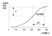
ここで、図4のステップn4に示す溶接部領域3内部の輝度値をもとに良否判定を行う過程について説明する。まず第1の方法として溶接部領域3の面積を利用する方法が挙げられる。図5にレーザー溶接の際の入熱量と溶接部領域3(熱影響部)の面積の関係を示す。レーザー溶接においては、溶接入熱量が大きいほど溶接部領域3の面積も大きくなることから、図5のグラフを利用して上記過程で抽出された溶接部領域3の面積をもとに入熱量を推定することができる。図5のグラフをもとに、十分な溶接を行うのに必要な入熱量範囲D1に対する熱影響部面積範囲S1を求めておき、レーザー溶接部1の赤外線画像から抽出された溶接部領域3の面積がS1の範囲内であれば良品と判定する。このように、溶接時の入熱量と溶接部領域3の面積との関係をもとに溶接状態の良否を判定することによって、簡易な方法で溶接状態の判定ができる。
【0028】
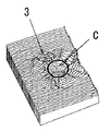
次に、良否判定を行う第2の方法について説明する。レーザースポット溶接においては、十分な入熱量が与えられた良品においては溶融する金属の量が多いため、図6に示すように溶接部領域3中央において溶融金属が溜まり、中央部が鏡面状となる。このため、良品のレーザー溶接部1を撮影した赤外線画像においては、図7(a)に示すように表面粗さが粗く赤外線放射率が高いため白く写るB部の内側に、上記鏡面状の部分(鏡面であるため赤外線放射率が低いC部)が黒く写る特徴が現れる。そこで、図7(b)に示すように、二値化した赤外線画像において当該溶接部領域3の内側にある基準値以上の大きさを持つ黒色部領域Cが観測される場合には良品であると判断する。しかして、十分な入熱量が与えられた時は中央部に鏡面状の特徴を生じることを利用して溶接状態の良否を判定するので、簡易な方法で溶接状態の判定ができる。
【0029】
ところで、上述した各欠陥検査方法においては、若干の虚報(欠陥を良品と判断する)が発生する可能性がある。上記方法における虚報発生原因とその対策方法について以下に説明する。
【0030】
レーザー溶接時の不良の一つとして、入熱量が不足している場合に、図8(a)の溶接片8,9の断面図に示すように、上側の溶接片8が加熱され、垂れ下がって下側溶接片9に充分接触し、下側溶接片9を加熱溶融させるまでの段階で上側の溶接片8だけが溶融してしまい、中央に穴20があいてしまう穴あき欠陥が存在する。この場合、赤外線画像においては、穴が開くことによりレーザー溶接部1の外周径が大きくなり、また穴から熱影響を受けていない下側の溶接片9が見えるため、図8(b)に示すように溶接部領域3の内側に黒色部21が観測されてしまうことにより、上記のいずれの方法による検査においても良品と誤判断されてしまう。
【0031】
このような虚報をなくすよう構成された装置を図9(a)に示す。図9(a)の装置は、検査対象となる溶接片8,9のレーザー溶接部1付近を上方から撮像する赤外線カメラ2に加えて、当該レーザー溶接部1に指向性のある赤外光を斜め方向から照射する赤外線源5と、赤外線源5に対して溶接片8,9を挟んで対向し、赤外光がレーザー溶接部1で正反射した光を捕捉できる位置に配設された第2の赤外線カメラ2aを設けたものである。ここで図10(a)は上方カメラでは良品と判断されてしまう穴あき欠陥を上記第2の赤外線カメラ2aで撮像した状態を示し、図10(b)は良品を上記第2の赤外線カメラ2aで撮像した状態を示す。図10(a)(b)を比較すればわかるように、穴あき欠陥では図10(a)のように、鏡面状の部分(下側の溶接片9)が下の位置にあるため上記赤外線源5からの光が届かず、図11(a)に示すように撮影した赤外線画像では溶接部領域3中央は暗い暗部4となって写る。これに対して図10(b)の良品の場合はレーザー溶接部1中央の鏡面部で正反射された赤外光が第2の赤外線カメラ2aに入射するので、図11(b)に示すように赤外線画像において溶接部領域3中央が白く写る。この違いを利用し、まず図9(a)に示す赤外線カメラ2により上方からレーザー溶接部1を観測し、溶接部領域3中央で輝度が低い部分があった場合には当該レーザー溶接部1を良品の候補とし、次に当該良品の候補について第2の赤外線カメラ2aによって撮影された画像において溶接部領域3中央で輝度が高くなる場合にはじめて良品として決定することにより、上記虚報を排除することができる。また、能動的に照射した赤外線光の正反射成分を捉える第2の赤外線カメラ2aを付加することによって、穴あき欠陥と良品を区別することができる。
【0032】
また、上記のように第2の赤外線カメラ2aを設ける代わりに、図9(b)に示すように上記第2の赤外線カメラ2aに相当する位置に配設された赤外線カメラ2を1台だけ使用するようにしてもよい。この場合、まず第1回目の撮像時には赤外線源5を消灯して撮影し、溶接部領域3を抽出したのち溶接部領域3中央に暗部4(鏡面部分)が観測されるものを良品候補とする。次に当該良品候補に対して赤外線源5を点灯した状態で撮影を行い、上記検査方法と同様中央部の輝度が高くなった場合に良品として決定する。しかして、1台の赤外線カメラ2で良品候補を抽出するカメラと良否判定を行うカメラを兼用する構成としたので、簡易な装置構成により穴あき欠陥と良品を区別することができる。
【0033】
上記虚報対策方法をさらに発展させた検査方法ついて以下に述べる。図9(a)および(b)の装置では、レーザー溶接部1中央に生じている鏡面部分が傾いていた場合は、第2の赤外線カメラ2aに赤外線光の正反射成分が届かず、誤って不良品と判断してしまう可能性がある。そこで、図12の検査装置では、赤外線源5を複数設けてある。これによりレーザー溶接部1中央に生じている鏡面部分が傾いていた場合にも、いずれかの赤外線源5からの赤外光が当該鏡面部で正反射して上記第2の赤外線カメラ2aへ入射することができるようになり、レーザー溶接部1中央の鏡面部分の向きが安定しない場合にも良品を不良品と判断してしまう誤りが少なくなり、穴あき欠陥と良品を正しく区別することができる。この方法は、第2の赤外線カメラ2aを複数設けたり、赤外線源5と赤外線カメラ2の少なくとも一方を移動させながら撮像し、赤外線源5と赤外線カメラ2の位置関係が変化していく中でいずれかの場所において鏡面部で赤外線源5からの正反射赤外光が赤外線カメラ2に入射するように構成しても構わない。
【0034】
また、上記虚報対策方法をさらに発展させた別の検査方法について以下に説明する。図13(a)のように上側の溶接片8が薄い場合や、同(b)のように上下の溶接片8,9の隙間が狭い場合には、上側の溶接片8上面と穴から見えている下側の溶接片9上面の段差が小さく、斜めから照射した赤外光が下側の溶接片9上面で正反射して第2の赤外線カメラ2aに入射してしまい、良品と誤判断されてしまう可能性がある。ここで図14(a)は段差の小さい穴あき欠陥の赤外線画像を示し、図14(b)は良品の赤外線画像を示す。図13(a)又は(b)に示したような穴あき欠陥品の場合は、下側の溶接片9上面で反射した赤外光の一部が段差で遮られるために、図14(a)のように溶接部領域3の中心からずれた位置に正反射成分Eが観測される。一方これに対して、図14(b)に示した良品の場合には、溶接部領域3とその中央の鏡面部分に段差がないため、図14(b)のように上記正反射成分Eは溶接部領域3の中央に観測される。これを利用し、レーザー溶接部1に赤外線を照射し、第2の赤外線カメラ2aで赤外線の正反射成分を観測することにより良否判定を行うにあたり、溶接部領域3の中央部分で正反射成分が観測された場合のみを良品とすることにより、さらに虚報を発生しにくい検査方法が実現できる。また上下の溶接片8,9の段差が小さい場合にも特別の装置を付加することなく穴あき欠陥と良品を正しく区別することができる。
【0035】
なお、穴あき欠陥と良品を区別するためのより直接的な方法としては、図15に示すように少なくともある2点H1,H2の高さを計測できる3次元計測装置7を併用し、上記レーザー溶接部1において周辺部と中心部のそれぞれ少なくとも2点H1,H2の高さ情報を取得し、両者の差が小さければ良品とし、両者の差が大きければ穴あき欠陥と判定するようにしてもよい。穴あき欠陥の場合は2点H1,H2の差が大きくなるが、良品の場合は小さくなることを利用することにより、穴あき欠陥と良品の区別など画像情報だけでは分かりにくい溶接状態の判定をさらに高い信頼度で行うことができる。勿論、2点H1,H2には限らず、3点以上の高さを計測してもよいものである。
【0036】
以上の検査方法において、対象とする被検査物6は溶接後雰囲気温度まで冷却した状態で撮影を行うようにしていたが、冷却した後で被検査物6全体を一様に加熱してから検査を行うようにしてもよい。ちなみに、熱影響をうけていない未溶接部分は、鏡面に近いため高温にしても赤外線放射の増加量は少ないが、熱影響を受けたレーザー溶接部(熱影響部)では、熱影響により金属が溶融し、ヒダ状の立体構造を持った表面となっているため、高温になるほど多くの赤外線を放射する。そのため、被検査物の温度が高い方が上記検査において赤外線画像におけるS/N比が高くなり、検査の信頼性が向上することがわかる。このことから被検査物6を一様に加熱するようにすることでレーザー溶接部1の明るい部分と、暗部(鏡面部分)との差が大きくなり、明暗パターンがはっきりするようになり、画像処理による検査の信頼性の向上を図ることができる。
【0037】
次に、上記のようにレーザー溶接部1を溶接後雰囲気温度まで冷却した後に、表面性状にともなう赤外線反射特性の差を用いて良否判定を行う方法において、さらにレーザー溶接部1に局所的に熱を与える方法を併用することにより、さらに精度の高い良否判定を行うことができる。以下説明する。
【0038】
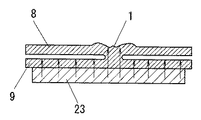
先ず図16は局所加熱を伴う第1の検査方法を説明する図である。図16は図1の検査装置のうち溶接片8,9の周辺のみを示す図であり、撮像装置の構成は図1と同一である。本方法においては、上下の溶接片8,9の各々に電極22a,22bが付けられており、電圧が印加できるようになっている。この両電極22a,22b間にある一定時間だけ電圧を印加すると、レーザー溶接部1はその抵抗に応じてジュール熱を発生し温度が上昇するが、レーザー溶接部1がきちんと溶着している良品では上下の溶接片8,9間の電気抵抗が小さいので、温度上昇が小さい。これに対して溶接不良(穴開き欠陥等)の場合は絶縁状態にあって全く温度上昇が生じないか、逆に接触抵抗が大きいため大きな温度上昇を示す。これを利用し、上下の溶接片8,9間に一定時間電圧を印加してレーザー溶接部1の温度上昇(具体的には赤外線画像における溶接部領域3内の輝度値の変化量)を赤外線カメラ2により測定し、それが予め定められた上限値と下限値の間にあれば良品と判断する。なお、上記輝度値の変化の観測においては、まず常温状態で上記方法により溶接部領域3を抽出しておき、当該領域内での輝度の平均値を加熱前後で比較する等の方法により温度上昇の大きさを評価するようにすればよい。このようにレーザー溶接部1に直接通電を行ってジュール熱による温度上昇を観測するようにしたので、外観だけで判断する場合より正確に溶接状態の良否判定ができる。
【0039】
次に、加熱を伴う第2の検査方法を図17に示す。図17は図1の検査装置のうち溶接片8,9の周辺のみを示す図であり、撮像装置の構成は図1と同一である。本例では、下側の溶接片9の下面に発熱体23を接触させ、下側の溶接片9のみを加熱している。これにより発熱体23から下側の溶接片9を経て上側の溶接片8へ熱伝導が生じるが、溶着部では良好な熱伝導を生じるのに対して、非溶着部では隙間があるため熱伝導が起こりにくい。これを利用して、下側の溶接片9を加熱しながら上方に配設された赤外線カメラ2によりレーザー溶接部1の温度変化(具体的には赤外線画像における溶接部領域3内の輝度値の変化量)を観測し、温度上昇がある基準値より大きければ良品であると判断することができる。つまり下側の溶接片9を加熱して上側の溶接片8へ熱伝導が生じる状態を観測するようにしたので、外観だけで判断する場合より正確に溶接状態の良否判定ができる。なお、上記輝度値の変化の観測においては、局所加熱を伴う第1の検査方法と同じようにまず常温状態で上記方法により溶接部領域3を抽出しておき、当該領域内での輝度の時間変化を求めるようにすればよい。なお、下側の溶接片9を加熱するにあたって、下側の溶接片9に発熱体23を接触させる方法以外に、下側から熱風や炎で加熱する方法も可能である。
【0040】
ところで、例えば電子部品などのように下側の溶接片9がすでに構造物に取り付けられた状態にあり、下側の溶接片9を熱伝導によって加熱することができない場合がある。このような場合には、図18に示すように、下側の溶接片9の両端に電極を取り付け、電圧を印加することにより下側の溶接片9自体にジュール熱を発生させる方法、或いは、下側の溶接片9の下部から高周波磁界を与え、渦電流を発生させてIH(induction heating)加熱する方法などにより加熱を行う方法を採用してもよいものである。
【0041】
【発明の効果】
上述のように請求項1記載の発明にあっては、被検査物となる2片の金属を重ね合わせ、その一方の表面にレーザーをスポット照射して溶接したレーザー溶接部を溶接後に検査する方法において、溶接後雰囲気温度まで冷却したレーザー溶接部を赤外線カメラで撮像し、得られた赤外線画像における輝度の差を被検査物表面の赤外線放射率の差を表す指標とみなして溶接部領域を検出する第1の過程と、上記溶接部領域の形状、上記溶接部領域内での赤外線画像の輝度値の分布パターン、上記分布パターンをもとに抽出された特徴量の少なくとも1つをもとに溶接の良否を判定する第2の過程とを有しているので、電子部品などの微細なレーザースポット溶接による熱影響部では表面性状(表面粗さ)が変化するものの、凹凸は極めて微細で3D(3次元)計測による検査は極めて困難であるが、本発明に係るレーザー溶接部の検査方法によれば赤外線画像の明るさの差(遠赤外線放射率の差)を利用することによりレーザー溶接部と未溶接部の表面性状の違いを検出することができるため、簡易な方法でレーザー溶接部の溶接状態検査が可能になる。しかも、溶接中のモニタリングではなく、溶接後のオフライン検査により検出するので、特に電子部品リードなどの薄く小さい部材の微細なレーザー溶接部の検査を精度良く行うことができるものである。
【0042】
また、少なくともレーザー溶接部の外周部では熱の影響により表面粗さが大きくなり、赤外線放射率が高くなることを利用して、赤外線画像において明るく見える部分を検出し、当該部分の外周輪郭より内側を溶接部領域として検出する方法を採用したので、赤外線放射率の高い部分を溶接部領域として抽出することにより、加熱を行うことなくレーザー溶接部を検出することができる。
【0043】
また請求項2記載の発明は、請求項1記載の効果に加えて、検出された溶接部領域の大きさを基準値と比較することにより溶接の良否を判定する方法を採用したので、溶接時の入熱量と溶接部領域の面積との関係をもとに溶接状態の良否を判定することで、簡易な方法で溶接状態の判定ができるものである。
【0044】
また請求項3記載の発明は、請求項1記載の効果に加えて、検出された溶接部領域内部の明るく見える外周輪郭の内側に所定の基準値以上の大きさを持つ暗部があれば良品と判定する方法を採用したので、十分な入熱量が与えられた時は中央部に鏡面状の特徴を生じることを利用して溶接状態の良否を判定することで、簡易な方法で溶接状態の判定ができる。
【0045】
また請求項4記載の発明は、請求項1記載の効果に加えて、上記赤外線カメラにより検出された溶接部領域内部で明るく見える外周輪郭の内側に所定の基準値以上の大きさを持つ暗部があれば良品候補とし、上記良品候補に赤外線を照射し、上記赤外線源の正反射を捉える方向に第2の赤外線カメラを配置して観測した時、溶接部領域中央の輝度が高くなる場合に良品と判定する方法を採用したので、能動的に照射した赤外線光の正反射成分を捉える赤外線カメラを付加することによって、穴あき欠陥と良品を区別することができる。
【0046】
また請求項5記載の発明は、請求項1記載の効果に加えて、被検査物に赤外線を照射する赤外線源と被検査物を撮像する赤外線カメラを、上記赤外線源から照射された赤外線の正反射光を赤外線カメラで捉えることができるような位置関係になるように配設し、まず赤外線源を消灯して撮影した赤外線画像を用いて検出された溶接部領域内部で明るく見える外周輪郭の内側に所定の基準値以上の大きさを持つ暗部があれば良品候補とし、次に赤外線源を点灯して観測した時、溶接部領域中央の輝度が高くなる場合に良品と判定する方法を採用したので、良品候補を抽出するカメラと良否判定を行うカメラを兼用する構成としたので、簡易な装置構成により穴あき欠陥と良品を区別することができる。
【0047】
また請求項6記載の発明は、請求項4又は請求項5記載の効果に加えて、良品候補に複数の方向から赤外線を照射していずれかの正反射光を捉えることができれば良品とする方法を採用したので、赤外線源を複数用いることで、仮りに溶接部領域中央の鏡面部分の向きが安定しない場合にも穴あき欠陥と良品を正しく区別することができる。
【0048】
また請求項7記載の発明は、請求項4又は請求項5記載の効果に加えて、良品候補を斜め方向から赤外線カメラで観測するようにし、赤外線画像において溶接部領域中央に正反射光が捉えられれば良品とし、溶接部領域中央からずれた位置に正反射光が捉えられれば不良とする方法を採用したので、上下の溶接片の段差が小さい場合にも特別の装置を付加することなく穴あき欠陥と良品を正しく区別することができる。
【0049】
また請求項8記載の発明は、請求項1〜7のいずれかに記載の効果に加えて、被検査物全体を一様に加熱したうえで検査を行う方法を採用したので、被検査物を一様に加熱するようにすることで赤外線画像のS/N比を改善し、検査の信頼性を向上させることができる。
【0050】
また請求項9記載の発明は、請求項1記載の効果に加えて、上記方法で良品候補と判断された被検査物について、上下の溶接片の間に電圧を与えることによってレーザー溶接部にジュール熱を発生させた状態で赤外線カメラにより撮像し、上記溶接部領域内での輝度値の変化を基準値と比較することによりレーザー溶接部の良否を判定する方法を採用したので、レーザー溶接部に直接通電を行ってジュール熱による温度上昇を観測するようにしたので、外観だけで判断する場合より正確に溶接状態の良否判定ができる。
【0051】
また請求項10記載の発明は、請求項1記載の効果に加えて、上記方法で良品候補と判断された被検査物について、下側の溶接片のみを加熱しながら上方より赤外線カメラで撮像し、上記溶接部領域内での輝度値の変化を基準値と比較することによりレーザー溶接部の良否を判定する方法を採用したので、下側の溶接片を加熱して上側の溶接片へ熱伝導が生じる状態を観測することにより、外観だけで判断する場合より正確に溶接状態の良否判定ができる。
【0052】
また請求項11記載の発明は、請求項10記載の効果に加えて、下側の溶接片に通電することにより下側の溶接片にジュール熱を発生させる方法を採用したので、下側の溶接片の下側に発熱体を設置できない構造の検査物でも、請求項10の方法による検査が可能になる。
【0053】
また請求項12記載の発明は、請求項10記載の効果に加えて、下側の溶接片に高周波磁界を与えて渦電流を発生させることにより加熱する方法を採用したので、下側の溶接片の下側に発熱体を設置できない構造の検査物でも、請求項10の方法による検査が可能になる。
【0054】
また請求項13記載の発明は、請求項1〜請求項12のいずれかに記載の効果に加えて、高さ計測装置により上記レーザー溶接部近辺の少なくとも2点の高さ情報を取得し、上記溶接部領域の輝度値とともに高さ情報を併用して良否判定を行う方法を採用したので、高さ情報を併用することにより穴あき欠陥と良品の区別など画像情報だけでは分かりにくい溶接状態の判定を高い信頼度で行うことができる。
【0055】
また請求項14記載の発明は、赤外線カメラと、赤外線カメラからの出力信号を量子化して画像として記憶する画像取り込み装置と、請求項1〜請求項13のいずれかの検査方法により赤外線画像を処理して溶接欠陥検査を行う画像処理装置とにより構成されているので、赤外線画像の明るさの差(遠赤外線放射率の差)を利用して、レーザー溶接部と未溶接部の表面性状の違いを画像処理装置にて検出することができ、簡易な構造でレーザー溶接部の溶接状態を検査することができるものである。
【図面の簡単な説明】
【図1】本発明の一実施形態において用いられる検査装置の構成を示す図である。
【図2】(a)は同上の赤外線画像の一例を示す図、(b)はレーザー溶接部の物理的構造を説明する図である。
【図3】同上の溶接部領域の抽出方法を説明する図である。
【図4】同上の検査処理手順を説明するためのフローチャートである。
【図5】同上のレーザー入熱量と熱影響部面積との関係を示すグラフである。
【図6】同上の良品のレーザー溶接部の物理的構造を説明する図である。
【図7】(a)(b)は同上の良否判定方法の原理を説明する図である。
【図8】(a)は同上の穴あき欠陥による虚報の発生を説明する図、(b)はその赤外線画像の一例を示す図である。
【図9】(a)は穴あき欠陥を判別するための装置構成を示す図、(b)は他の装置構成を示す図である。
【図10】同上の穴あき欠陥と良品の判別方法の原理を説明する図である。
【図11】(a)(b)は穴あき欠陥と良品の赤外線画像の違いを説明する図である。
【図12】穴あき欠陥を判別するための他の実施形態の装置構成を示す図である。
【図13】(a)(b)は同上の穴あき欠陥を判別するための他の方法を説明する図である。
【図14】(a)(b)は同上の穴あき欠陥を判別するための更に他の方法を説明する図である。
【図15】(a)は穴あき欠陥を判別するための更に他の実施形態の装置構成を示す図、(b)は溶接部の高さ情報の2点を説明する図である。
【図16】局所加熱を伴う溶接部検査方法の装置構成を示す図である。
【図17】局所加熱を伴う他の溶接部検査方法の装置構成を示す図である。
【図18】下側の溶接片の両側に電圧を与えて下側の溶接片自体を発熱させる場合を説明する図である。
【符号の説明】
1 レーザー溶接部
2 赤外線カメラ
2a 第2の赤外線カメラ
3 溶接部領域
4 暗部
5 赤外線源
6 被検査物
8 上側の溶接片
9 下側の溶接片
10 画像取り込み装置
11 画像処理装置[0001]
BACKGROUND OF THE INVENTION
The present invention is based on the fact that the present invention superimposes welding defects of a laser welded portion where two pieces of metal to be inspected are overlapped and laser-spotted from one surface is welded instead of monitoring during welding. In particular, the present invention relates to an off-line inspection method and apparatus for fine laser welding of thin and small members such as electronic component leads.
[0002]
[Prior art]
Conventionally, as a method for inspecting a laser welded portion, as in the inspection method described in JP-A-5-71932, slit-like laser light is projected onto a laser welded portion, and the reflected light of the laser light is referred to as a laser projection direction. There is a method using three-dimensional shape measurement by a so-called light cutting method, in which a three-dimensional shape of a laser weld is obtained by observing with a camera from different directions.
[0003]
In addition, as a method for inspecting a laser welded portion using an infrared camera, the laser welded portion is heated as inspected in Japanese Patent Laid-Open No. 5-34204, Japanese Patent Laid-Open No. 8-122051, and Japanese Patent Laid-Open No. 52-59046. There is a method of measuring the size of the welded part by measuring the temperature distribution around the laser welded part with an infrared camera in the process of performing the process or the cooling process after heating (including heating by welding heat).
[0004]
[Problems to be solved by the invention]
The above-described conventional inspection method using three-dimensional shape measurement is effective in welding methods in which a laser welded portion is greatly raised, such as butt welding or fillet welding using a filler, but laser spot welding, particularly a lead portion of an electronic component. In the fine welding such as the above, since the change of the shape accompanying the welding is extremely small, a highly accurate three-dimensional shape measuring method is required, which is difficult to apply.
[0005]
In the latter method of measuring the temperature distribution in the latter process of heating the laser spot welded by laser spot welding or in the cooling process after heating (including heating by welding heat), the laser weld has a certain mass ( This is an effective method when it has a heat capacity). For example, in a laser welded part of a very thin and low mass member such as a lead part of an electronic component, the temperature change due to heating occurs in a very short time. There is a problem that it is difficult to accurately measure the temperature distribution by the image.
[0006]
The present invention has been invented in view of the problems of the above-described conventional example, and the object is to perform an off-line inspection after welding, in particular, a fine laser welded portion of a thin and small member such as an electronic component lead. It is an object of the present invention to provide a method and an apparatus for inspecting a laser welded part capable of accurately performing the inspection of the laser welding, improving the reliability of the inspection and improving the accuracy of the quality determination.
[0007]
[Means for Solving the Problems]
In order to solve the above-mentioned problem, in the present invention, two pieces of metal to be inspected 6 are overlapped, and
[0008]
Further, by utilizing the fact that the surface roughness is increased due to the influence of heat and the infrared emissivity is increased at least in the outer peripheral portion of the laser welded
[0009]
Moreover, it is preferable to determine the quality of the welding by comparing the detected size of the
[0010]
Further, if there is a
[0011]
Further, if there is a
[0012]
In addition, the
[0013]
In addition, it is preferable that the non-defective product is irradiated with infrared rays from a plurality of directions and any specularly reflected light can be captured. In this case, by using a plurality of
[0014]
Further, a good product candidate is observed with the
[0015]
Further, it is preferable to perform the inspection after the
[0016]
Further, in order to accurately determine the quality of the welded state, a voltage is applied between the upper and
[0017]
In addition, it is preferable to generate Joule heat in the
[0018]
Further, it is preferable to heat the
[0019]
Further, at least two points H in the vicinity of the
[0020]
Furthermore, the inspection apparatus for the
[0021]
DETAILED DESCRIPTION OF THE INVENTION
Hereinafter, the present invention will be described based on embodiments shown in the accompanying drawings.
[0022]
FIG. 1 is a diagram showing a configuration of an inspection apparatus that performs off-line determination of laser welding by the method of the present invention. This inspection apparatus superimposes two pieces of metal (
[0023]
FIG. 2A shows an example of an infrared image obtained by imaging the laser welded
[0024]
The laser welded
[0025]
However, although the surface properties (surface roughness) change in the heat-affected zone due to fine laser spot welding such as electronic parts, the unevenness is extremely fine and inspection by 3D (three-dimensional) measurement is extremely difficult. According to the inspection method of the laser welded
[0026]
Next, an example of the extraction and inspection procedure of the weld zone of the
[0027]
Here, the process of performing the pass / fail determination based on the luminance value inside the
[0028]
Next, a second method for determining pass / fail is described. In laser spot welding, a good product to which a sufficient amount of heat input is given has a large amount of metal to be melted. Therefore, as shown in FIG. 6, the molten metal accumulates in the center of the
[0029]
By the way, in each of the defect inspection methods described above, there is a possibility that some false information (determining a defect as a non-defective product) may occur. The cause of the false alarm occurrence in the above method and the countermeasure method will be described below.
[0030]
As one of the defects at the time of laser welding, when the heat input amount is insufficient, as shown in the cross-sectional view of the
[0031]
An apparatus configured to eliminate such false information is shown in FIG. The apparatus shown in FIG. 9 (a) adds directional infrared light to the laser welded
[0032]
Further, instead of providing the second
[0033]
The inspection method, which is a further development of the above-mentioned false alarm countermeasure method, will be described below. In the apparatus of FIGS. 9A and 9B, when the mirror surface portion generated in the center of the laser welded
[0034]
Further, another inspection method, which is a further development of the above-mentioned false alarm countermeasure method, will be described below. When the
[0035]
As a more direct method for distinguishing perforated defects from non-defective products, there are at least two points H as shown in FIG. 1 , H 2 In combination with a three-dimensional measuring device 7 that can measure the height of the
[0036]
In the above inspection method, the object to be inspected 6 was photographed in a state where it was cooled to the ambient temperature after welding, but after cooling, the entire object to be inspected 6 was uniformly heated and then inspected. May be performed. By the way, the unwelded part that is not affected by heat is close to the mirror surface, so the amount of increase in infrared radiation is small even at high temperatures. However, in laser-welded parts (heat-affected parts) that are affected by heat, Since the surface is melted and has a fold-like three-dimensional structure, more infrared rays are emitted as the temperature rises. Therefore, it can be seen that the higher the temperature of the inspection object, the higher the S / N ratio in the infrared image in the above inspection, and the reliability of the inspection is improved. Therefore, by uniformly heating the
[0037]
Next, after the laser welded
[0038]
First, FIG. 16 is a diagram for explaining a first inspection method involving local heating. FIG. 16 is a diagram showing only the periphery of the
[0039]
Next, a second inspection method involving heating is shown in FIG. FIG. 17 is a view showing only the periphery of the
[0040]
By the way, there is a case where the
[0041]
【The invention's effect】
As described above, in the first aspect of the present invention, a method of inspecting a laser welded portion, which is formed by superimposing two pieces of metal to be inspected and spot-irradiating a laser on one surface thereof after welding. In this case, the laser welded portion cooled to the ambient temperature after welding is imaged with an infrared camera, and the difference in brightness in the obtained infrared image is regarded as an index indicating the difference in infrared emissivity on the surface of the object to be detected. Based on at least one of the first process, the shape of the weld region, the distribution pattern of the brightness value of the infrared image in the weld region, and the feature value extracted based on the distribution pattern And the second process of judging the quality of the welding, the surface properties (surface roughness) change in the heat-affected zone due to the fine laser spot welding of electronic parts, etc., but the unevenness is extremely fine. Inspection by D (three-dimensional) measurement is extremely difficult, but according to the inspection method for laser welds according to the present invention, laser welding is performed by utilizing the difference in brightness of infrared images (difference in far-infrared emissivity). Since it is possible to detect the difference in surface properties between the welded portion and the unwelded portion, it is possible to inspect the welding state of the laser welded portion by a simple method. In addition, since detection is performed not by monitoring during welding but by offline inspection after welding, it is possible to accurately inspect a fine laser welded portion of a thin and small member such as an electronic component lead.
[0042]
Ma Little At least the outer peripheral part of the laser welded part is affected by heat, and the surface roughness increases and the infrared emissivity increases. Since the method of detecting as the weld zone is adopted, the laser weld zone can be detected without heating by extracting the portion having a high infrared emissivity as the weld zone.
[0043]
Also Claim 2 The described
[0044]
Also Claim 3 The described
[0045]
Also Claim 4 The described
[0046]
Also Claim 5 The described
[0047]
Also Claim 6 The described
[0048]
Also Claim 7 The described
[0049]
Also Claim 8 The described invention Claims 1-7 In addition to the effect described in any one of the above, since the method of performing inspection after heating the entire object to be inspected uniformly is adopted, the infrared image can be obtained by heating the object to be inspected uniformly. The / N ratio can be improved and the reliability of inspection can be improved.
[0050]
Also Claim 9 The described
[0051]
Also Claim 10 The described
[0052]
Also Claim 11 The described
[0053]
Also Claim 12 The described
[0054]
Also Claim 13 The invention described in
[0055]
Also Claim 14 The invention described is an infrared camera, an image capturing device that quantizes an output signal from the infrared camera and stores the image as an image, and claims 1 to Claim 13 Because it is composed of an image processing device that inspects welding defects by processing infrared images by any of the inspection methods described above, a laser utilizing the difference in brightness of infrared images (difference in far-infrared emissivity) The difference in surface properties between the welded portion and the unwelded portion can be detected by an image processing apparatus, and the welding state of the laser welded portion can be inspected with a simple structure.
[Brief description of the drawings]
FIG. 1 is a diagram showing a configuration of an inspection apparatus used in an embodiment of the present invention.
FIG. 2A is a diagram showing an example of the above infrared image, and FIG. 2B is a diagram for explaining a physical structure of a laser welded portion.
FIG. 3 is a diagram for explaining a method of extracting a welded portion region as described above.
FIG. 4 is a flowchart for explaining the inspection processing procedure of the above.
FIG. 5 is a graph showing the relationship between the laser heat input and the heat-affected zone area.
FIG. 6 is a view for explaining the physical structure of a good laser welded part.
FIGS. 7A and 7B are diagrams for explaining the principle of the pass / fail judgment method of the above.
FIG. 8A is a diagram for explaining generation of a false alarm due to a holed defect, and FIG. 8B is a diagram showing an example of an infrared image thereof.
9A is a diagram showing a device configuration for discriminating perforated defects, and FIG. 9B is a diagram showing another device configuration.
FIG. 10 is a diagram for explaining the principle of a method for discriminating between perforated defects and non-defective products.
FIGS. 11A and 11B are diagrams for explaining a difference between a perforated defect and a non-defective infrared image. FIGS.
FIG. 12 is a diagram showing an apparatus configuration of another embodiment for discriminating a hole defect.
FIGS. 13A and 13B are diagrams for explaining another method for discriminating the holed defect.
FIGS. 14A and 14B are views for explaining still another method for discriminating the holed defect.
FIG. 15A is a diagram showing a device configuration of still another embodiment for discriminating perforated defects, and FIG. 15B is a diagram for explaining two points of height information of a welded portion.
FIG. 16 is a diagram showing an apparatus configuration of a weld inspection method with local heating.
FIG. 17 is a diagram showing a device configuration of another welded portion inspection method involving local heating.
FIG. 18 is a diagram illustrating a case where voltage is applied to both sides of the lower weld piece to cause the lower weld piece itself to generate heat.
[Explanation of symbols]
1 Laser weld
2 Infrared camera
2a Second infrared camera
3 Weld zone
4 Dark areas
5 Infrared source
6 Inspection object
8 Upper weld piece
9 Lower welding piece
10 Image capture device
11 Image processing device
Claims (14)
Priority Applications (1)
| Application Number | Priority Date | Filing Date | Title |
|---|---|---|---|
| JP2001258658A JP4140218B2 (en) | 2001-08-28 | 2001-08-28 | Inspection method and apparatus for laser welds |
Applications Claiming Priority (1)
| Application Number | Priority Date | Filing Date | Title |
|---|---|---|---|
| JP2001258658A JP4140218B2 (en) | 2001-08-28 | 2001-08-28 | Inspection method and apparatus for laser welds |
Publications (2)
| Publication Number | Publication Date |
|---|---|
| JP2003065985A JP2003065985A (en) | 2003-03-05 |
| JP4140218B2 true JP4140218B2 (en) | 2008-08-27 |
Family
ID=19086137
Family Applications (1)
| Application Number | Title | Priority Date | Filing Date |
|---|---|---|---|
| JP2001258658A Expired - Fee Related JP4140218B2 (en) | 2001-08-28 | 2001-08-28 | Inspection method and apparatus for laser welds |
Country Status (1)
| Country | Link |
|---|---|
| JP (1) | JP4140218B2 (en) |
Families Citing this family (12)
| Publication number | Priority date | Publication date | Assignee | Title |
|---|---|---|---|---|
| EP2094429B9 (en) * | 2006-11-04 | 2017-08-16 | TRUMPF Werkzeugmaschinen GmbH + Co. KG | Method and device for process monitoring during the working of a material |
| DE102006061794B3 (en) * | 2006-12-21 | 2008-04-30 | Thermosensorik Gmbh | Welded joint i.e. welded point, checking method, involves examining region from sequence of regions of heat flow dynamic according to sudden extension of its periphery, where welding lens is evaluated according to its position and size |
| WO2009003702A1 (en) * | 2007-07-04 | 2009-01-08 | Thermosensorik Gmbh | Method for the automatic inspection of a welding seam using heat flow thermography |
| JP4967931B2 (en) * | 2007-08-31 | 2012-07-04 | パナソニック株式会社 | Capacitor inspection method and manufacturing method using the inspection method |
| JP4648373B2 (en) * | 2007-09-13 | 2011-03-09 | 有限会社新工 | Inspection method for small metal joints |
| JP5704454B2 (en) * | 2011-04-28 | 2015-04-22 | スズキ株式会社 | Image processing apparatus and image processing method |
| JP5920401B2 (en) * | 2013-05-21 | 2016-05-18 | Jfeスチール株式会社 | Ultrasonic flaw detection apparatus and method for electric sewing tube and quality assurance method |
| WO2018074161A1 (en) * | 2016-10-18 | 2018-04-26 | 日産自動車株式会社 | Welding quality inspection method and welding quality inspection device |
| CN111638127A (en) * | 2020-06-01 | 2020-09-08 | 江西优特汽车技术有限公司 | Method for detecting welding reliability of soft-packaged battery cell tab |
| CN113504239B (en) * | 2021-06-10 | 2022-12-02 | 上海西信信息科技股份有限公司 | Quality control data analysis method |
| WO2024043006A1 (en) * | 2022-08-26 | 2024-02-29 | パナソニックIpマネジメント株式会社 | Inspection system, inspection device, and inspection method |
| CN116399907A (en) * | 2023-06-07 | 2023-07-07 | 保融盛维(沈阳)科技有限公司 | Industrial electronic detonator spot welding defect infrared imaging nondestructive detection method |
-
2001
- 2001-08-28 JP JP2001258658A patent/JP4140218B2/en not_active Expired - Fee Related
Also Published As
| Publication number | Publication date |
|---|---|
| JP2003065985A (en) | 2003-03-05 |
Similar Documents
| Publication | Publication Date | Title |
|---|---|---|
| JP4991893B2 (en) | Method and apparatus for determining pass / fail of minute diameter wire bonding | |
| JP6301951B2 (en) | Sample inspection method and system using thermography | |
| CN102441737B (en) | Apparatus and method for determining shape of end of welding bead | |
| US8541746B2 (en) | Process and system for the nondestructive quality determination of a weld seam, and a welding device | |
| JP6560220B2 (en) | Method and apparatus for inspecting inspection system for detection of surface defects | |
| JP4140218B2 (en) | Inspection method and apparatus for laser welds | |
| US7044634B2 (en) | Thermography method | |
| JP4917975B2 (en) | Inspection failure analysis method and inspection failure analysis apparatus | |
| EP2102639B1 (en) | System and method for the defect analysis of workpieces | |
| US20050134842A1 (en) | Electrical circuit conductor inspection | |
| JP2007528490A (en) | System and method for inspecting electrical circuits utilizing reflective and fluorescent images | |
| EP2141489B1 (en) | Thermographic inspection apparatus | |
| JP7390680B2 (en) | Laser welding quality inspection method and laser welding quality inspection device | |
| JP2017078624A (en) | Method and device for inspecting connectability of sample | |
| JP2008016778A (en) | Semiconductor testing device and testing method | |
| JP7412237B2 (en) | Inspection equipment and welding equipment | |
| JP5622338B2 (en) | Method for discriminating and checking foreign matter and scratch marks in semiconductor device manufacturing process | |
| JP2861649B2 (en) | Steel plate weld inspection method | |
| JPH07191016A (en) | Method and device for inspecting plated-through soldered joint | |
| JP6232760B2 (en) | Optical nondestructive inspection method and optical nondestructive inspection apparatus | |
| JP2016142567A (en) | Inspection method and device | |
| JP2001269787A (en) | Method of deciding welding state | |
| JPH03176654A (en) | Method and device for inspecting solder zone | |
| JPH0360882A (en) | Method for deciding quality of welding state | |
| JP2023045310A (en) | Device for estimating diameter of nugget part in spot welding, method for estimating diameter of nugget part in spot welding, and program for estimating diameter of nugget part in spot welding |
Legal Events
| Date | Code | Title | Description |
|---|---|---|---|
| A621 | Written request for application examination |
Free format text: JAPANESE INTERMEDIATE CODE: A621 Effective date: 20050613 |
|
| A977 | Report on retrieval |
Free format text: JAPANESE INTERMEDIATE CODE: A971007 Effective date: 20061019 |
|
| A131 | Notification of reasons for refusal |
Free format text: JAPANESE INTERMEDIATE CODE: A131 Effective date: 20080219 |
|
| A521 | Written amendment |
Free format text: JAPANESE INTERMEDIATE CODE: A523 Effective date: 20080421 |
|
| TRDD | Decision of grant or rejection written | ||
| A01 | Written decision to grant a patent or to grant a registration (utility model) |
Free format text: JAPANESE INTERMEDIATE CODE: A01 Effective date: 20080520 |
|
| A01 | Written decision to grant a patent or to grant a registration (utility model) |
Free format text: JAPANESE INTERMEDIATE CODE: A01 |
|
| A61 | First payment of annual fees (during grant procedure) |
Free format text: JAPANESE INTERMEDIATE CODE: A61 Effective date: 20080602 |
|
| FPAY | Renewal fee payment (event date is renewal date of database) |
Free format text: PAYMENT UNTIL: 20110620 Year of fee payment: 3 |
|
| FPAY | Renewal fee payment (event date is renewal date of database) |
Free format text: PAYMENT UNTIL: 20110620 Year of fee payment: 3 |
|
| S533 | Written request for registration of change of name |
Free format text: JAPANESE INTERMEDIATE CODE: R313533 |
|
| FPAY | Renewal fee payment (event date is renewal date of database) |
Free format text: PAYMENT UNTIL: 20110620 Year of fee payment: 3 |
|
| R350 | Written notification of registration of transfer |
Free format text: JAPANESE INTERMEDIATE CODE: R350 |
|
| FPAY | Renewal fee payment (event date is renewal date of database) |
Free format text: PAYMENT UNTIL: 20120620 Year of fee payment: 4 |
|
| FPAY | Renewal fee payment (event date is renewal date of database) |
Free format text: PAYMENT UNTIL: 20120620 Year of fee payment: 4 |
|
| FPAY | Renewal fee payment (event date is renewal date of database) |
Free format text: PAYMENT UNTIL: 20130620 Year of fee payment: 5 |
|
| LAPS | Cancellation because of no payment of annual fees |