JP4139987B2 - Roller with core for image forming apparatus, method for forming the same, and print medium feeding assembly - Google Patents
Roller with core for image forming apparatus, method for forming the same, and print medium feeding assembly Download PDFInfo
- Publication number
- JP4139987B2 JP4139987B2 JP2002108860A JP2002108860A JP4139987B2 JP 4139987 B2 JP4139987 B2 JP 4139987B2 JP 2002108860 A JP2002108860 A JP 2002108860A JP 2002108860 A JP2002108860 A JP 2002108860A JP 4139987 B2 JP4139987 B2 JP 4139987B2
- Authority
- JP
- Japan
- Prior art keywords
- hollow core
- sleeve
- roller
- print media
- surrounding
- Prior art date
- Legal status (The legal status is an assumption and is not a legal conclusion. Google has not performed a legal analysis and makes no representation as to the accuracy of the status listed.)
- Expired - Fee Related
Links
Images


Classifications
-
- B—PERFORMING OPERATIONS; TRANSPORTING
- B65—CONVEYING; PACKING; STORING; HANDLING THIN OR FILAMENTARY MATERIAL
- B65H—HANDLING THIN OR FILAMENTARY MATERIAL, e.g. SHEETS, WEBS, CABLES
- B65H27/00—Special constructions, e.g. surface features, of feed or guide rollers for webs
-
- B—PERFORMING OPERATIONS; TRANSPORTING
- B65—CONVEYING; PACKING; STORING; HANDLING THIN OR FILAMENTARY MATERIAL
- B65H—HANDLING THIN OR FILAMENTARY MATERIAL, e.g. SHEETS, WEBS, CABLES
- B65H2404/00—Parts for transporting or guiding the handled material
- B65H2404/10—Rollers
- B65H2404/13—Details of longitudinal profile
- B65H2404/135—Body
- B65H2404/1351—Pipe element
Landscapes
- Delivering By Means Of Belts And Rollers (AREA)
- Rolls And Other Rotary Bodies (AREA)
- Handling Of Cut Paper (AREA)
Description
【0001】
【発明の属する技術分野】
本発明は、概して画像形成装置に関し、さらに詳しくは、画像形成装置を通してプリント媒体を送るためのローラに関する。
【0002】
【従来の技術】
プリント媒体上に文字及び/又はその他の画像を印刷し及び/又は複写するための通常の画像形成装置は、プリント媒体経路を通してプリント媒体を送るための1つ又は複数のプリント媒体送りアセンブリーを備えている。典型的には、プリント媒体送りアセンブリーは、それぞれ1つ又は複数のローラを備え、これらのローラは、それぞれプリント媒体に接触しかつ画像形成装置のプリント媒体経路を通してプリント媒体を送るために、軸上に取り付けられている。ローラは、しばしば中実のゴム材料から形成されている。
【0003】
ゴム材料からローラを形成することによって、ローラについて、適当な摩擦係数、高度な耐磨耗性及び製造の容易さのような望ましい特性が得られる。例えばゴム材料からローラを形成することによって、ローラは、プリント媒体を損傷することなく、プリント媒体に接触しかつ画像形成装置を通して効果的にプリント媒体を送る微妙な摩擦係数を提供する。加えてゴム材料からローラを形成することによって、ローラは、通常の成形技術によって形成することができ、かつ同心的なローラを形成するために容易に機械加工することができる。
【0004】
残念ながら中実ゴム材料のローラの形成は、比較的高価である。画像形成装置のそれぞれのプリント媒体送りアセンブリーには、しばしば多数のローラが設けられているので、個々のローラの費用は、急速に増大する。従って、ローラの全体的なコストによって、画像形成装置のコストが著しく増大することがある。
【0005】
【発明が解決しようとする課題】
本発明は、従来の中実ゴムローラの利点を生かしたまま、さらに画像形成装置の製造の容易さ及び/又は製造効率、又は印刷品質に影響を及ぼすことなく、製造コストが安価な、画像形成装置に利用するローラ、及びその形成方法、並びにプリント媒体送りアセンブリーを提供することを目的とする。
【0006】
【課題を解決するための手段】
本発明の一態様は、画像形成装置においてプリント媒体に接触するのに適したローラを提供することにある。ローラは、第1の材料から形成されかつ内側表面及び外側表面を有する中空のコアと、第2の材料から形成されかつ中空のコアの一部を囲むスリーブとを備えている。また、スリーブは、中空のコアの内側表面の一部を囲む内側部分、及び中空のコアの外側表面の一部を囲む外側部分を有する。
【0007】
本発明の別の態様において、前記第2の材料としてゴム材料を用い、第1の材料としてプラスチック材料を用いることができる。
【0008】
本発明の別の態様において、中空のコアは、第1の端部及び第2の端部を有し、スリーブの内側部分は、中空のコアの第1の端部と第2の端部との間に延びて形成されている。さらに、前記スリーブの外側部分は、中空のコアの第1の端部と第1の端部との間に延びて形成されている。
【0009】
本発明の別の態様において、スリーブの外側部分は、中空のコアの第1の端部から中空のコアの第2の端部に向かって延びる第1の部分、及び中空のコアの第2の端部から中空のコアの第1の端部に向かって延びる第2の部分を有する。このようにして、第1の部分及び第2の部分は、中空のコア上において軸線方向に間隔を置いて設けられている。
【0010】
本発明の別の態様において、スリーブの内側部分は、内側表面及び外側表面を有する。このスリーブの内側部分の外側表面は、中空のコアの内側表面に接触している。
【0011】
本発明の別の態様において、スリーブの外側部分は、内側表面及び外側表面を有する。このスリーブの外側部分の内側表面は、中空のコアの外側表面に接触し、かつ外側部分の外側表面は、プリント媒体に接触するようになっている。
【0012】
本発明の別の態様において、中空のコアは、第1の端部及び第2の端部を有し、スリーブは、中空のコアの第1の端部及び第2の端部の少なくとも一方の一部を囲む少なくとも1つの端部分を含む。本発明の別の態様において、スリーブの少なくとも1つの端部分は、内側表面及び外側表面を含む。このようにして少なくとも1つの端部分の内側表面は、中空のコアの第1の端部及び第2の端部の少なくとも1つに接触する。一態様において、スリーブの少なくとも1つの端部分には、複数の開口が形成されている。これによって、中空のコアは、それぞれの開口を通してスリーブ内に挿入することができる。
【0013】
本発明の更に別の態様は、画像形成装置のためのローラを形成する方法を提供する。この形成方法は、第1の材料から形成されかつ内側表面及び外側表面を有する中空のコアを設け、第2の材料から形成されたスリーブによって前記中空のコアの一部を囲むことを含む。スリーブによって中空のコアを囲むことは、スリーブの内側部分によって中空のコアの内側表面の一部を囲み、かつスリーブの外側部分によって中空のコアの外側表面の一部を囲むことを含む。
【0014】
本発明の更に別の態様では、プリント媒体送りアセンブリーを提供する。プリント媒体送りアセンブリーは、軸、及び軸上に取り付けられた少なくとも1つのローラを有する。少なくとも1つのローラは、中空のコア、中空のコアの内側表面の一部を囲む内側スリーブ、及び中空のコアの外側表面の一部を囲む外側スリーブを有する。このようにして、内側スリーブは軸に接触する。さらに、中空のコアは、第1の材料から形成され、内側スリーブ及び外側スリーブは、第2の材料から形成されている。
【0015】
本発明の更に別の態様は、プリント媒体送りアセンブリーを通ってプリント媒体を送る少なくとも1つのプリント媒体送りアセンブリーを有する画像形成装置である。このプリント媒体送りアセンブリーは、画像形成装置に取り付けられた軸、及び該軸上に取り付けられた少なくとも1つのローラを備えている。該ローラは、プリント媒体に接触するようになっており、かつ中空のコア、中空のコアの内側表面の一部を囲む内側スリーブ、及び中空のコアの外側表面の一部を囲む外側スリーブを有する。このようにして、内側スリーブは軸に接触し、かつ外側スリーブは、プリント媒体に接触するようになっている。さらに、中空のコアは、第1の材料から形成されており、内側スリーブ及び外側スリーブは、第2の材料から形成されている。
【0016】
なお、本発明は、画像形成装置のプリント媒体送りアセンブリーのためのローラを提供する。このローラは、中空のコア、及び中空のコアを囲むゴム材料からなるスリーブを有する。このようにして、ゴム材料からなるスリーブは、プリント媒体に接触し、画像形成装置のプリント媒体経路を通して送り、プリント媒体送りアセンブリーに取り付けられたときに、該プリント媒体送りアセンブリーの軸にローラを摩擦力によって連結される。
【0017】
【発明の実施の形態】
以下の詳細な説明において、好適な実施例を添付図面を用いて説明する。しかし、本発明は、この実施例に限定されるものではなく、その他の実施例を採用することができる。また、本発明の権利範囲から離れることなく、構造的又は論理的な変更を行なうこともできる。従って、以下の詳細な説明は、本発明を限定する意味にとらえるものではなく、本発明の権利範囲は、特許請求の範囲によって定義される。
【0018】
図1は、本発明による少なくとも1つのプリント媒体送りアセンブリー10を有する画像形成装置100の一部分を示す実施例の一つである。画像形成装置100は、入力紙トレイ12、ピックローラアセンブリー14、駆動ローラアセンブリー16、及びピンチローラアセンブリー18を備えている。入力紙トレイ12は、紙、又はカードストック、スライド、マイラ等、及びそれらに類するようなプリント媒体13の供給を確保する。このようにしてピックローラアセンブリー14は、プリント媒体13の最も上のシートに接触し、これを引き寄せて、このシートを駆動ローラアセンブリー16とピンチローラアセンブリー18との間に送って挟み込ませる。こうして、駆動ローラアセンブリー16は、画像形成装置100を通してプリント媒体13を送り進める。
【0019】
ピックローラアセンブリー14、駆動ローラアセンブリー16及びピンチローラアセンブリー18は、それぞれプリント媒体送りアセンブリー10の一実施例である。従って、プリント媒体送りアセンブリー10は、画像形成装置100のプリント媒体経路を通してプリント媒体13を移動させ、及び/又は送給ルートを形成するものである。図1は、画像形成装置100を簡略化した概略図である。画像形成装置100は、例えばプリンタ、フォトコピー、ファックス機、スキャナ等のようなプリント装置及び/又は複写装置を含む。
【0020】
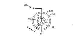
図2は、プリント媒体送りアセンブリー10の一実施例の一部分を示している。プリント媒体送りアセンブリー10は、軸20、及び少なくとも1つのローラ30を有する。軸20は、軸線22を有する。一実施例において、ローラ30と軸線22を中心に回転させるために、軸20を画像形成装置10に回転可能に取り付けている。このようにして軸20は、駆動軸及び/又はアイドラ軸とすることができる。図2においては、軸20は、円形の横断面を有するように示されているが、正方形又は多角形のようなその他の形状の横断面を有する軸としてもよい。
【0021】
ローラ30は、軸20に取り付けられており、かつ軸20の軸線22と一致する軸線32を有する。一実施例において、ローラ30は、回転するために軸20に取り付けられている。このようにしてローラ30は、駆動ローラ及び/又はアイドラローラとすることができる。図2では、ローラ30が一つだけ軸20に取り付けられているが、一方、軸20上に多数のローラ30を取り付けることもできる。この場合、ローラ30を寄せ集めて取り付け及び/又は軸20に沿って互いに離して取り付けてもよい。
【0022】
図3〜図5に示すように、ローラ30は、コアを有するローラであり、かつ中空のコア40及びスリーブ50を備えている。中空のコア40は、内径41及び外径42を有し、内径41における内側表面43、及び外径42における外側表面44を有する。また、中空のコア40は、第1の端部45及び第2の端部46を有する。一実施例において、中空のコア40の内径41は、軸20を収容できる寸法に形成されている。中空のコア40は、円筒形で環状の外形を有するように示されているが、例えば楕円形、カム形又は非同心的な外形などのその他の外形状とすることができる。
【0023】
スリーブ50は、中空のコア40の一部を囲み又はカバーするように、中空のコア40の回りに配置されている。スリーブ50は、内側スリーブ部分51及び外側スリーブ部分52を有する。このように、内側スリーブ部分51は、中空のコア40の内側表面43の一部を囲んでおり、外側スリーブ部分52は、中空のコア40の外側表面44の一部を囲んでいる。したがって外側スリーブ部分52は、内側スリーブ部分51と同心状に配設されている。一実施例において、内側スリーブ部分51及び外側スリーブ部分52は、両方とも中空のコア40の第1の端部45と第2の端部46との間に延びて形成されている。したがってスリーブ50は、第1の端部45と第2の端部46との間において中空のコア40に沿って延びるように形成されている。
【0024】
内側スリーブ部分51は、内側表面511及び外側表面512を有する。外側スリーブ部分52は、内側表面521及び外側表面522を有する。このようにして内側スリーブ部分51の外側表面512は、中空のコア40の内側表面43に接触し、かつ外側スリーブ部分52の内側表面521は、中空のコア40の外側表面44に接触している。
【0025】
内側スリーブ部分51の内側表面511は、好ましくは、軸20の外形に対応する外形を有する。一実施例において、前述したように、軸20は、円形横断面を有する。したがって、軸20にローラ30を取り付けたときに、内側スリーブ部分51が軸20に接触して係合するように、内側スリーブ部分51の内側表面511は円筒形表面に形成されている。しかし、前述したように、軸20の横断面形状を円形以外の形状にすることができる。よって、軸20の横断面形状が円形以外の場合、内側スリーブ部分51の内側表面511は、軸20に接触して係合する形状に形成されている。
【0026】
一実施例において、中空のコア40の外側表面44は円筒形の表面である。従って、外側スリーブ部分52の内側表面521も、中空のコア40の外側表面44を囲みかつ接触するように、円筒形である。しかし、中空のコア40の外側表面44の形状を前述した円筒形以外とすることができる。この場合は、外側スリーブ部分52の内側表面521は、中空のコア40の外形に対応する外形形状を有する。従って、外側スリーブ部分52の内側表面521は、中空のコア40の外側表面44を囲みかつ接触するような形状に形成されている。
【0027】
一実施例において、外側スリーブ部分52の外側表面522は、円筒形の表面である。このようにして、外側スリーブ部分52の外側表面522は、プリント媒体13が画像形成装置100を通って送られるとき、プリント媒体13に接触する。従って、ローラ30とプリント媒体13の接触は、スリーブ50によって行なわれる。外側スリーブ部分52及び外側表面522は、円筒形として示されているが、スリーブ50の外側スリーブ部分52を楕円又はカム形のような偏心した形状とすることができる。この場合は、外側部分52の外側表面522は、偏心した表面に形成される。
【0028】
一実施例において、ローラ30のスリーブ50は、一対の端部スリーブ部分53を有する。該端部スリーブ部分53は、中空のコア40の第1の端部45の一部及び第2の端部46の一部を覆っている。このように、端部スリーブ部分53は、それぞれ内側表面531及び外側表面532を有する。従って、端部スリーブ部分53の内側表面531は、中空のコア40の第1の端部45及び第2の端部46に接触している。端部スリーブ部分53は、好ましくは、環状に形成され、内側スリーブ部分51及び外側スリーブ部分52と隣接して、これらと一体に形成されている。しかし、スリーブ50に端部スリーブ部分53を設けないようにしてもよい。
【0029】
一実施例において、スリーブ50はゴム材料から形成されている。このとき、スリーブ50のゴム材料は、画像形成装置100を通ってプリント媒体13を送るために、プリント媒体13に接触する。スリーブ50に用いる適当なゴム材料として、例えばポリウレタンを用いることができる。ポリウレタンは、紙又はその他のプリント媒体上に望ましくない堆積物を残す添加物を含まないことが判明したからである。
【0030】
中空のコア40は、好ましくは、その形を維持するために十分に硬くかつ製造コストが安価な材料から形成される。一実施例において、中空のコア40は、プラスチック材料から形成される。中空のコア40に適したプラスチック材料として、例えばポリプロピレン及びナイロンを用いることができる。しかしながら、中空のコア40をアルミニウムのようなその他の材料から形成してもよい。
【0031】
スリーブ50は、好ましくは、中空のコア40の回りに形成される。一実施例において、スリーブ50は、中空のコア40の回りにモールド成形される。中空のコア40の回りにスリーブ50をモールド成形するために、スリーブ50を中空のコア40の回りに成形する間に、中空のコア40を保持し及び/又は位置決めするための点を提供するように形成された、1つ又は複数の空洞又はノッチ47を中空のコア40は有する。このように、スリーブ50を形成するときに、ノッチ47に対応する一又は複数の開口54をスリーブ50に形成することができる。
【0032】
開口54は、スリーブ50が中空のコア40の回りに成形される間に、中空のコア40が成形装置の結合部分によって所定の位置に維持され又は保持される範囲を表わしている。従って、一度、スリーブ50が中空のコア40の回りに形成され、かつ成形装置の結合部分が取り除かれるとき、開口54が残る。従って、開口54は、中空のコア40への通路を提供する。
【0033】
一実施例において、ノッチ47は、中空のコア40の第1の端部45及び第2の端部46に設けられている。従って、開口54は、端部スリーブ部分53を有するスリーブ50が形成されるとき、スリーブ50の端部スリーブ部分53に形成される。図5には、3つのノッチ47及びこれに対応する3つの開口54が、それぞれ中空のコア40及びスリーブ50に形成されるものとして示されているが、本発明はこれに限定されず、どのような数のノッチ47及びこれに対応する開口54も、中空のコア40及びスリーブ40に形成することができる。
【0034】
中空のコア40は、中空のコア40の回りにスリーブ50を成形する間に、中空のコア40を維持し及び/又は位置決めするために中空のコア40に形成されたノッチ47を設けている。しかし、ノッチ47以外の手段を用いてスリーブ50を成形する間に保持し及び/又は位置決めするようにしてもよい。中空のコア40は、例えば中空のコア40の第1の端部45及び第2の端部46を同時に接触することによって、保持し又は位置決めすることができる。しかし、開口54は、スリーブ50を中空のコア40の回りにモールド成形する間に、成形装置の結合部分によって中空のコア40が所定の位置に維持され又は保持される範囲を表わしているので、スリーブ50が中空のコア40の回りにモールド成形されるとき、開口54は、いぜんとしてスリーブ50に形成することができる。
【0035】
一実施例において、スリーブ50は、内側スリーブ部分51と端部スリーブ部分53との間に斜めに形成されたエッジ55、及び、外側スリーブ部分52と端部スリーブ部分53との間に斜めに形成されたエッジ56とを備えている。
【0036】
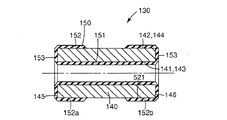
図6は、プリント媒体送りアセンブリー10の別の実施例の一部を示している。プリント媒体送りアセンブリー110は、軸120及び少なくとも1つのローラ130を有する。軸120は、軸20と同様に構成され、軸線122を有する。従って、軸20の全体的な説明は、軸120にも適用することができる。ローラ130は、軸120上に取り付けられており、軸120の軸線122と一致する軸線132を有する。
【0037】
図7〜図9によれば、ローラ130は、コアを有するローラであり、かつ中空のコア140及びスリーブ150を備えている。中空のコア140及びスリーブ150は、以下に説明するものを除いて、それぞれ中空のコア40及びスリーブ50と同様の構造を有する。従って、中空のコア40及びスリーブ50の全体的な説明は、それぞれ中空のコア140及びスリーブ150にも適用可能である。
【0038】
中空のコア40と同様な構造を有する中空のコア140は、内径141及び外径142を有し、かつ内径141における内側表面143及び外径142における外側表面144を有する。さらに、中空のコア140は、第1の端部145及び第2の端部146を有する。
【0039】
スリーブ50と同様な構造を有するスリーブ150は、中空のコア140の一部を囲む又はカバーするように、中空のコア140の回りに配置されている。スリーブ150は、内側スリーブ部分151及び外側スリーブ部分152を有する。このように、内側スリーブ部分151は、中空のコア140の内側表面143の一部を囲んでおり、かつ外側スリーブ部分152は、中空のコア140の外側表面144の一部を囲んでいる。このように、外側スリーブ部分152は、内側スリーブ部分151と同心状に配設されている。
【0040】
一実施例において、内側スリーブ部分151は、中空のコア140の第1の端部145と第2の端部146との間に延びて形成されている。従って、スリーブ150は、第1の端部145と第2の端部146との間において中空のコア140に沿って延びている。しかし外側スリーブ部分152は、第1の外側スリーブ部分152a及び第2の外側スリーブ部分152bを有する。従って、第1の外側スリーブ部分152a及び第2の外側スリーブ部分152bは、中空のコア140上において軸線方向に間隔を置いて配置されている。このように、中空のコア140の一部は、第1の外側スリーブ部分152aと第2の外側スリーブ部分152bとの間において露出したままである。したがって中空のコア140の一部は、第1の端部145と第2の端部146との間において露出したままである。
【0041】
一実施例において、第1の外側スリーブ部分152aは、中空のコア140の第1の端部145に隣接しており、かつ第2の外側スリーブ部分152bは、中空のコア140の第2の端部146に隣接している。このようにして第1の外側スリーブ部分152aは、中空のコア140に沿って第1の端部145から第2の端部146に向かって延びており、また、第2の外側スリーブ部分152bは、中空のコア140に沿って第2の端部146から第1の端部145に向かって延びている。従って、スリーブ150は、スリーブ150の外側スリーブ部分152が第1の外側スリーブ部分152a及び第2の外側スリーブ分152bを有するということを除いて、スリーブ50と同様である。しかし、第1の外側スリーブ部分152a及び第2の外側スリーブ部分152bは、それぞれ外側スリーブ部分52と似た構造を有する。
【0042】
一実施例において、ローラ130のスリーブ150は、一対の端部スリーブ部分153,153を有する。端部スリーブ部分53が中空のコア40の第1の端部45及び第2の端部46を覆っているのと同様の方法で、端部スリーブ部分153は、中空のコア140の第1の端部145及び第2の端部146を覆っている。端部スリーブ部分153は、好ましくは、略環状に形成されており、内側スリーブ部分151及び外側スリーブ部分152に隣接し、かつこれと一体に形成される。さらに詳細には、一方の端部スリーブ部分153は、第1の外側スリーブ部分152aに隣接し、かつこれらと一体に形成されており、他方の端部スリーブ部分153は、第2の外側スリーブ部分152bに隣接し、かつこれと一体に形成されている。
【0043】
スリーブ150及びコア140は、好ましくは、前述したスリーブ50及び中空のコア40と同様に、それぞれゴム材料及びプラスチック材料から形成されている。従って、中空のコア140の回りにスリーブ150をモールド成形するために、第1の外側スリーブ部分152a及び第2の外側スリーブ部分152bが形成されるときに、第1の端部145と第2の端部146との間に露出したままになった中空のコア140の部分によって、中空のコア140を保持し及び/又は位置決めすることができる。
【0044】
一実施例において、スリーブ150は、内側スリーブ部分151及び端部スリーブ部分153の間に斜めに形成されたエッジ155と、外側スリーブ部分152a,152b及び端部スリーブ部分153の間に斜めに形成されたエッジ156と、端部スリーブ部分153に対向する外側スリーブ部分152a,152bの端部に斜めに形成されたエッジ157とを有する。
【0045】
以上説明した本発明に係るローラによれば、次の作用効果が得られる。
ゴム材料から形成される中空のコア40及びスリーブ50によってローラ30を形成することによって、ローラ30の全体的なコストを削減することができ、一方、ローラ30にゴム材料を用いる利点は維持される。さらに、中空のコア40及びスリーブ50を有するローラ30を形成することによって、それぞれのローラ30のために必要とされるゴム材料の量は、このローラ30と比較可能な寸法を有する中実のゴムローラよりも大幅に減少する。このように、ゴム材料は例えば中空のコア40のプラスチック材料よりも高価なので、中空のコア40及びスリーブ50を有するローラ30の製造コストは減少する。さらに、中空のコア140に沿って軸線方向に間隔を置いて外側スリーブ部分152a,152bを配置したローラ130を形成することによって、それぞれのローラ130に必要なゴム材料の量がさらに減少するので、ローラ130の製造コストをさらに削減することができる。なお、この場合においても、ローラ130のゴム材料についての利点は維持されている。
【0046】
ゴム材料から形成された内側スリーブ部分51及び外側スリーブ部分52を有するスリーブ50を備えたローラ30を形成することによって、数々の有利な効果が得られる。これは、ローラ130についても同様である。例えば内側スリーブ部分51のゴム材料は、軸20にローラ30を取り付けるときに、ローラ30を軸20とともに回転させるために軸20にローラ30を摩擦によって連結する。従って、軸20にローラ30を取り付けるために、軸20のローレット切りのような追加的な連結工程を組み込む必要はない。さらに、外側スリーブ部分52のゴム材料は、プリント媒体13に接触するための同心的な外側表面をローラ30に備えるために通常の機械加工技術を利用して精密に機械加工することができる。さらに外側スリーブ部分52のゴム材料によって、例えば誤供給、多重供給及び/又はプリント媒体の損傷なしに、画像形成装置100のプリント媒体経路を通してプリント媒体13を移動しかつ/又は送ることができる微妙なローラ30の摩擦係数が得られる。
【0047】
これまで、特定の実施例を図示して有利な実施例を説明したが、同じ目的を達成するために本発明の技術思想に基づき、種々の変形および変更が可能である。化学、機械、電気機械、電気及びコンピュータの技術の当事者は、本発明がきわめて広い種類の実施例において実行できることをすでに認識しているであろう。本出願は、これまで説明した有利な実施例のあらゆる適用又は変形を含むものとする。従って、本発明は特許請求の範囲及びその均等物だけによって制限されることが、明らかに意図されている。
【図面の簡単な説明】
【図1】本発明によるプリント媒体送りアセンブリーを有する画像形成装置の一部を示す概略図である。
【図2】本発明によるローラの一実施例のプリント媒体送りアセンブリーの一部を示す斜視図である。
【図3】図2のプリント媒体送りアセンブリーのローラを示す側面図である。
【図4】図3の線4−4による横断面図である。
【図5】図2のプリント媒体送りアセンブリーのローラを構成する中空のコアとスリーブを示す斜視図である。
【図6】本発明によるローラの別の実施例を含むプリント媒体送りアセンブリーの一部を示す斜視図である。
【図7】図6のプリント媒体送りアセンブリーのローラの端面図である。
【図8】図7の線8−8による横断面図である。
【図9】図6のプリント媒体送りアセンブリーのローラを構成する中空のコアとスリーブを示す斜視図である。
【符号の説明】
10 プリント媒体送りアセンブリ
13 プリント媒体
20,120 軸
30,130 ローラ
40,140 中空のコア
43,143 内側表面
44,144 外側表面
45,145 第1の端部
46,146 第2の端部
50,150 スリーブ
51,151 内側スリーブ部分
52,152 外側スリーブ部分
100 画像形成装置
152a 第1の外側スリーブ部分
152b 第2の外側スリーブ部分[0001]
BACKGROUND OF THE INVENTION
The present invention relates generally to image forming devices, and more particularly to a roller for feeding print media through the image forming device.
[0002]
[Prior art]
A typical image forming apparatus for printing and / or copying characters and / or other images on a print media includes one or more print media feed assemblies for feeding the print media through the print media path. Yes. Typically, the print media feed assemblies each include one or more rollers, each of which is on-axis to contact the print media and feed the print media through the print media path of the imaging device. Is attached. The rollers are often formed from a solid rubber material.
[0003]
By forming the roller from a rubber material, desirable properties such as a suitable coefficient of friction, a high degree of wear resistance and ease of manufacture are obtained for the roller. For example, by forming the roller from a rubber material, the roller provides a subtle coefficient of friction that contacts the print media and effectively transports the print media through the imaging device without damaging the print media. In addition, by forming the roller from a rubber material, the roller can be formed by conventional molding techniques and can be easily machined to form a concentric roller.
[0004]
Unfortunately, the formation of rollers of solid rubber material is relatively expensive. Since each print media feed assembly of an image forming apparatus is often provided with a number of rollers, the cost of the individual rollers increases rapidly. Accordingly, the cost of the image forming apparatus may increase significantly due to the overall cost of the rollers.
[0005]
[Problems to be solved by the invention]
The present invention is an image forming apparatus that has the advantage of the conventional solid rubber roller and that has low manufacturing cost without affecting the ease and / or manufacturing efficiency of the image forming apparatus or the print quality. It is an object of the present invention to provide a roller, a method of forming the same, and a print medium feeding assembly.
[0006]
[Means for Solving the Problems]
One aspect of the present invention is to provide a roller suitable for contacting a print medium in an image forming apparatus. The roller includes a hollow core formed from a first material and having an inner surface and an outer surface, and a sleeve formed from a second material and surrounding a portion of the hollow core. The sleeve also has an inner portion surrounding a portion of the inner surface of the hollow core and an outer portion surrounding a portion of the outer surface of the hollow core.
[0007]
In another aspect of the present invention, a rubber material can be used as the second material, and a plastic material can be used as the first material.
[0008]
In another aspect of the invention, the hollow core has a first end and a second end, and the inner portion of the sleeve includes the first end and the second end of the hollow core. It extends between the two. Further, the outer portion of the sleeve is formed to extend between the first end and the first end of the hollow core.
[0009]
In another aspect of the invention, the outer portion of the sleeve includes a first portion that extends from a first end of the hollow core toward a second end of the hollow core, and a second portion of the hollow core. A second portion extending from the end toward the first end of the hollow core; In this way, the first portion and the second portion are provided on the hollow core at an interval in the axial direction.
[0010]
In another aspect of the invention, the inner portion of the sleeve has an inner surface and an outer surface. The outer surface of the inner portion of the sleeve is in contact with the inner surface of the hollow core.
[0011]
In another aspect of the invention, the outer portion of the sleeve has an inner surface and an outer surface. The inner surface of the outer portion of the sleeve is in contact with the outer surface of the hollow core, and the outer surface of the outer portion is in contact with the print medium.
[0012]
In another aspect of the invention, the hollow core has a first end and a second end, and the sleeve is at least one of the first end and the second end of the hollow core. Including at least one end portion surrounding the portion. In another aspect of the invention, at least one end portion of the sleeve includes an inner surface and an outer surface. In this way, the inner surface of the at least one end portion contacts at least one of the first end and the second end of the hollow core. In one aspect, a plurality of openings are formed in at least one end portion of the sleeve. This allows the hollow core to be inserted into the sleeve through the respective opening.
[0013]
Yet another aspect of the present invention provides a method of forming a roller for an image forming apparatus. The forming method includes providing a hollow core formed from a first material and having an inner surface and an outer surface, and surrounding a portion of the hollow core by a sleeve formed from a second material. Surrounding the hollow core with the sleeve includes surrounding a portion of the inner surface of the hollow core with the inner portion of the sleeve and surrounding a portion of the outer surface of the hollow core with the outer portion of the sleeve.
[0014]
In yet another aspect of the invention, a print media feed assembly is provided. The print media feed assembly has a shaft and at least one roller mounted on the shaft. The at least one roller has a hollow core, an inner sleeve surrounding a portion of the inner surface of the hollow core, and an outer sleeve surrounding a portion of the outer surface of the hollow core. In this way, the inner sleeve contacts the shaft. Further, the hollow core is formed from a first material, and the inner sleeve and the outer sleeve are formed from a second material.
[0015]
Yet another aspect of the invention is an image forming apparatus having at least one print media feed assembly that feeds print media through the print media feed assembly. The print media feed assembly includes a shaft mounted on the image forming apparatus and at least one roller mounted on the shaft. The roller is in contact with the print media and has a hollow core, an inner sleeve surrounding a portion of the inner surface of the hollow core, and an outer sleeve surrounding a portion of the outer surface of the hollow core. . In this way, the inner sleeve is in contact with the shaft and the outer sleeve is in contact with the print medium. Further, the hollow core is formed from a first material, and the inner sleeve and the outer sleeve are formed from a second material.
[0016]
The present invention also provides a roller for a print media feed assembly of an image forming apparatus. This roller has a hollow core and a sleeve made of a rubber material surrounding the hollow core. In this way, the sleeve of rubber material contacts the print media, feeds through the print media path of the imaging device, and rubs the roller against the shaft of the print media feed assembly when attached to the print media feed assembly. Linked by force.
[0017]
DETAILED DESCRIPTION OF THE INVENTION
In the following detailed description, preferred embodiments will be described with reference to the accompanying drawings. However, the present invention is not limited to this embodiment, and other embodiments can be adopted. Also, structural or logical changes can be made without departing from the scope of the present invention. The following detailed description is, therefore, not to be taken in a limiting sense, and the scope of the present invention is defined by the appended claims.
[0018]
FIG. 1 is one embodiment illustrating a portion of an
[0019]
Pick
[0020]
FIG. 2 illustrates a portion of one embodiment of the print
[0021]
The
[0022]
As shown in FIGS. 3 to 5, the
[0023]
The
[0024]
[0025]
The
[0026]
In one embodiment, the outer surface 44 of the
[0027]
In one embodiment, the
[0028]
In one embodiment, the
[0029]
In one embodiment, the
[0030]
The
[0031]
The
[0032]
The
[0033]
In one embodiment, the
[0034]
The
[0035]
In one embodiment, the
[0036]
FIG. 6 illustrates a portion of another embodiment of the print
[0037]
7 to 9, the
[0038]
The
[0039]
A
[0040]
In one embodiment, the
[0041]
In one embodiment, the first
[0042]
In one embodiment, the
[0043]
The
[0044]
In one embodiment, the
[0045]
According to the roller according to the present invention described above, the following operational effects can be obtained.
By forming the
[0046]
By forming the
[0047]
The advantageous embodiments have been described with reference to specific embodiments so far, but various modifications and changes can be made based on the technical idea of the present invention in order to achieve the same object. Those skilled in the chemical, mechanical, electromechanical, electrical and computer arts will already recognize that the present invention can be implemented in a very wide variety of embodiments. This application is intended to cover any applications or variations of the preferred embodiments described above. Therefore, it is manifestly intended that this invention be limited only by the claims and the equivalents thereof.
[Brief description of the drawings]
FIG. 1 is a schematic diagram illustrating a portion of an image forming apparatus having a print media feed assembly according to the present invention.
FIG. 2 is a perspective view of a portion of a print media feed assembly of one embodiment of a roller according to the present invention.
FIG. 3 is a side view showing a roller of the print media feed assembly of FIG. 2;
4 is a cross-sectional view taken along line 4-4 of FIG.
5 is a perspective view showing a hollow core and a sleeve constituting a roller of the print medium feeding assembly of FIG. 2. FIG.
FIG. 6 is a perspective view of a portion of a print media feed assembly that includes another embodiment of a roller according to the present invention.
7 is an end view of a roller of the print media feed assembly of FIG. 6. FIG.
8 is a cross-sectional view taken along line 8-8 of FIG.
9 is a perspective view showing a hollow core and a sleeve constituting a roller of the print medium feeding assembly of FIG. 6;
[Explanation of symbols]
10 Print Media Feed Assembly
13 Print media
20,120 axes
30,130 rollers
40,140 hollow core
43,143 inner surface
44,144 outer surface
45,145 first end
46,146 second end
50,150 sleeve
51,151 Inner sleeve part
52,152 Outer sleeve part
100 Image forming apparatus
152a first outer sleeve portion
152b second outer sleeve portion
Claims (16)
第2の材料から形成されかつ前記中空のコアの部分を囲むスリーブとを備え、
該スリーブが、中空のコアの内側表面の部分を囲む内側部分と、中空のコアの外側表面の部分を囲む外側部分と、前記中空のコアの第1の端部及び第2の端部の少なくとも一方の一部を覆い、前記内側部分及び前記外側部分と隣接して前記内側部分及び前記外側部分と一体に形成される端部スリーブ部分とを有することを特徴とする、
画像形成装置におけるプリント媒体に接触するよう適合されたローラ。A hollow core formed from a first material and having an inner surface and an outer surface;
A sleeve formed from a second material and surrounding a portion of the hollow core;
Said sleeve, and an inner portion surrounding the portion of the inner surface of the hollow core, and an outer portion surrounding the portion of the outer surface of the hollow core, at least a first end and a second end of said hollow core covers part of one, characterized by chromatic and said inner portion and said end sleeve portion outer portion and adjacent is formed integrally with the inner portion and the outer portion,
A roller adapted to contact a print medium in an image forming apparatus.
第2の材料から形成されたスリーブによって前記中空のコアの部分を囲むことによって、スリーブの内側部分で中空のコアの内側表面の部分を囲み、かつスリーブの外側部分によって中空のコアの外側表面の部分を囲み、前記中空のコアの第1の端部及び第2の端部の少なくとも一方の一部を、前記内側部分及び前記外側部分と隣接して前記内側部分及び前記外側部分と一体に形成される端部スリーブ部分によって覆うステップを含んでなることを特徴とする、
画像形成装置のためのローラを形成する方法。Providing a hollow core formed of a first material and having an inner surface and an outer surface;
Surrounding the hollow core portion with a sleeve formed of a second material surrounds the hollow core inner surface portion with the sleeve inner portion, and the sleeve outer portion surrounds the hollow core outer surface portion. enclose the part, at least one of a portion of the first end and a second end of said hollow core, integrally with the inner portion and the outer portion adjacent to the inner portion and the outer portion Comprising the step of covering with an end sleeve portion to be formed ,
A method of forming a roller for an image forming apparatus.
Applications Claiming Priority (2)
| Application Number | Priority Date | Filing Date | Title |
|---|---|---|---|
| US09/832,607 US6550992B2 (en) | 2001-04-11 | 2001-04-11 | Cored roller for image forming device |
| US09/832607 | 2001-04-11 |
Publications (3)
| Publication Number | Publication Date |
|---|---|
| JP2002326734A JP2002326734A (en) | 2002-11-12 |
| JP2002326734A5 JP2002326734A5 (en) | 2005-09-22 |
| JP4139987B2 true JP4139987B2 (en) | 2008-08-27 |
Family
ID=25262151
Family Applications (1)
| Application Number | Title | Priority Date | Filing Date |
|---|---|---|---|
| JP2002108860A Expired - Fee Related JP4139987B2 (en) | 2001-04-11 | 2002-04-11 | Roller with core for image forming apparatus, method for forming the same, and print medium feeding assembly |
Country Status (3)
| Country | Link |
|---|---|
| US (1) | US6550992B2 (en) |
| EP (1) | EP1249351A1 (en) |
| JP (1) | JP4139987B2 (en) |
Families Citing this family (3)
| Publication number | Priority date | Publication date | Assignee | Title |
|---|---|---|---|---|
| DE10151816B4 (en) * | 2001-10-20 | 2011-04-28 | Manroland Ag | Sleeve-shaped printing or transfer mold and apparatus for chamfering the length ends of a sleeve-shaped printing or transfer form |
| US20060132520A1 (en) * | 2004-12-16 | 2006-06-22 | Bledsoe James D | Multiple-function inkjet printing system with single motor for carriage and scan head motion |
| TW200726705A (en) * | 2006-01-09 | 2007-07-16 | Lite On Technology Corp | Paper storage box capable of taking paper contactlessly |
Family Cites Families (8)
| Publication number | Priority date | Publication date | Assignee | Title |
|---|---|---|---|---|
| US5363129A (en) | 1991-10-31 | 1994-11-08 | Hewlett-Packard Company | Printing media feed and retaining apparatus for a thermal ink jet printer/plotter |
| JPH09250539A (en) | 1996-03-19 | 1997-09-22 | Shin Etsu Polymer Co Ltd | Semiconductive roll, and manufacture of it |
| US6168269B1 (en) | 1997-01-30 | 2001-01-02 | Hewlett-Packard Co. | Heated inkjet print media support system |
| US5882131A (en) | 1997-03-11 | 1999-03-16 | Hewlett-Packard Company | Printer drive roller with grit-blasted surface |
| US5932313A (en) | 1997-04-17 | 1999-08-03 | Lexmark International, Inc. | Rubber-based paper feed rollers |
| US6042109A (en) | 1997-08-29 | 2000-03-28 | Hewlett-Packard Company | Sheet feeding device with compact media path for paper-based and photographic media |
| US6042100A (en) * | 1998-03-03 | 2000-03-28 | Hewlett-Packard Company | Soft pinch roller to reduce hand-off error |
| US6139140A (en) | 1998-09-29 | 2000-10-31 | Hewlett-Packard Company | Inkjet printing apparatus with media handling system providing small bottom margin capability |
-
2001
- 2001-04-11 US US09/832,607 patent/US6550992B2/en not_active Expired - Lifetime
-
2002
- 2002-01-24 EP EP02001703A patent/EP1249351A1/en not_active Withdrawn
- 2002-04-11 JP JP2002108860A patent/JP4139987B2/en not_active Expired - Fee Related
Also Published As
| Publication number | Publication date |
|---|---|
| JP2002326734A (en) | 2002-11-12 |
| EP1249351A1 (en) | 2002-10-16 |
| US20020151421A1 (en) | 2002-10-17 |
| US6550992B2 (en) | 2003-04-22 |
Similar Documents
| Publication | Publication Date | Title |
|---|---|---|
| EP0511424B1 (en) | Sheetlike article conveying roller assembly | |
| US7258499B2 (en) | Wire dot printer head and wire dot printer | |
| JP4139987B2 (en) | Roller with core for image forming apparatus, method for forming the same, and print medium feeding assembly | |
| KR100375193B1 (en) | ink ribbon cassette | |
| US7086628B2 (en) | Ink ribbon core | |
| JP4018704B2 (en) | Ribbon cassette | |
| JPH0971345A (en) | Pressing roller | |
| KR102644232B1 (en) | Friction shaft | |
| JP2004264688A (en) | Image carrier driving mechanism | |
| JPH11230172A (en) | Sliding bearing of resin | |
| JPH05130752A (en) | Armature | |
| JP2002326734A5 (en) | ||
| JP3109602U (en) | Support cylinder and replacement ink ribbon | |
| JP3715717B2 (en) | Drive transmission device and sheet material feeding device | |
| KR100189552B1 (en) | Capstan roller device for color printer | |
| JP2004059185A (en) | Roller for conveyance | |
| JPH0542989Y2 (en) | ||
| JPS5913077Y2 (en) | Recording paper wrapping rotating drum device | |
| JP2003160254A (en) | Recording paper conveying roller and its manufacturing method | |
| JP2001158161A (en) | Ink ribbon taking up member | |
| KR200306467Y1 (en) | Paper pick up cluch for office automation apparatus | |
| JP3067025U (en) | Versatile ink ribbon core | |
| JP6219677B2 (en) | Dot print head and image forming apparatus | |
| JPH10319756A (en) | Fixing device | |
| WO2004076189A1 (en) | Platen assembly for thermal printer |
Legal Events
| Date | Code | Title | Description |
|---|---|---|---|
| A521 | Written amendment |
Free format text: JAPANESE INTERMEDIATE CODE: A523 Effective date: 20050411 |
|
| A621 | Written request for application examination |
Free format text: JAPANESE INTERMEDIATE CODE: A621 Effective date: 20050411 |
|
| A711 | Notification of change in applicant |
Free format text: JAPANESE INTERMEDIATE CODE: A711 Effective date: 20060623 |
|
| A977 | Report on retrieval |
Free format text: JAPANESE INTERMEDIATE CODE: A971007 Effective date: 20070219 |
|
| A521 | Written amendment |
Free format text: JAPANESE INTERMEDIATE CODE: A523 Effective date: 20070302 |
|
| A131 | Notification of reasons for refusal |
Free format text: JAPANESE INTERMEDIATE CODE: A131 Effective date: 20070508 |
|
| RD02 | Notification of acceptance of power of attorney |
Free format text: JAPANESE INTERMEDIATE CODE: A7422 Effective date: 20070510 |
|
| A521 | Written amendment |
Free format text: JAPANESE INTERMEDIATE CODE: A523 Effective date: 20070807 |
|
| A711 | Notification of change in applicant |
Free format text: JAPANESE INTERMEDIATE CODE: A711 Effective date: 20071101 |
|
| A521 | Written amendment |
Free format text: JAPANESE INTERMEDIATE CODE: A821 Effective date: 20071101 |
|
| A072 | Dismissal of procedure [no reply to invitation to correct request for examination] |
Free format text: JAPANESE INTERMEDIATE CODE: A073 Effective date: 20071211 |
|
| A072 | Dismissal of procedure [no reply to invitation to correct request for examination] |
Free format text: JAPANESE INTERMEDIATE CODE: A073 Effective date: 20080129 |
|
| A131 | Notification of reasons for refusal |
Free format text: JAPANESE INTERMEDIATE CODE: A131 Effective date: 20080311 |
|
| A521 | Written amendment |
Free format text: JAPANESE INTERMEDIATE CODE: A523 Effective date: 20080325 |
|
| A521 | Written amendment |
Free format text: JAPANESE INTERMEDIATE CODE: A523 Effective date: 20080325 |
|
| TRDD | Decision of grant or rejection written | ||
| A01 | Written decision to grant a patent or to grant a registration (utility model) |
Free format text: JAPANESE INTERMEDIATE CODE: A01 Effective date: 20080430 |
|
| A01 | Written decision to grant a patent or to grant a registration (utility model) |
Free format text: JAPANESE INTERMEDIATE CODE: A01 |
|
| A61 | First payment of annual fees (during grant procedure) |
Free format text: JAPANESE INTERMEDIATE CODE: A61 Effective date: 20080528 |
|
| FPAY | Renewal fee payment (event date is renewal date of database) |
Free format text: PAYMENT UNTIL: 20110620 Year of fee payment: 3 |
|
| R150 | Certificate of patent or registration of utility model |
Ref document number: 4139987 Country of ref document: JP Free format text: JAPANESE INTERMEDIATE CODE: R150 Free format text: JAPANESE INTERMEDIATE CODE: R150 |
|
| FPAY | Renewal fee payment (event date is renewal date of database) |
Free format text: PAYMENT UNTIL: 20120620 Year of fee payment: 4 |
|
| R250 | Receipt of annual fees |
Free format text: JAPANESE INTERMEDIATE CODE: R250 |
|
| FPAY | Renewal fee payment (event date is renewal date of database) |
Free format text: PAYMENT UNTIL: 20130620 Year of fee payment: 5 |
|
| R250 | Receipt of annual fees |
Free format text: JAPANESE INTERMEDIATE CODE: R250 |
|
| R250 | Receipt of annual fees |
Free format text: JAPANESE INTERMEDIATE CODE: R250 |
|
| R250 | Receipt of annual fees |
Free format text: JAPANESE INTERMEDIATE CODE: R250 |
|
| R250 | Receipt of annual fees |
Free format text: JAPANESE INTERMEDIATE CODE: R250 |
|
| R250 | Receipt of annual fees |
Free format text: JAPANESE INTERMEDIATE CODE: R250 |
|
| R250 | Receipt of annual fees |
Free format text: JAPANESE INTERMEDIATE CODE: R250 |
|
| LAPS | Cancellation because of no payment of annual fees | ||
| S111 | Request for change of ownership or part of ownership |
Free format text: JAPANESE INTERMEDIATE CODE: R313113 |
|
| R371 | Transfer withdrawn |
Free format text: JAPANESE INTERMEDIATE CODE: R371 |