JP4139908B2 - Gas conduit leak detection method and detection apparatus - Google Patents
Gas conduit leak detection method and detection apparatus Download PDFInfo
- Publication number
- JP4139908B2 JP4139908B2 JP30434698A JP30434698A JP4139908B2 JP 4139908 B2 JP4139908 B2 JP 4139908B2 JP 30434698 A JP30434698 A JP 30434698A JP 30434698 A JP30434698 A JP 30434698A JP 4139908 B2 JP4139908 B2 JP 4139908B2
- Authority
- JP
- Japan
- Prior art keywords
- gas
- pressure
- pipe
- conduit
- branch
- Prior art date
- Legal status (The legal status is an assumption and is not a legal conclusion. Google has not performed a legal analysis and makes no representation as to the accuracy of the status listed.)
- Expired - Lifetime
Links
Images


Description
【0001】
【発明の属する技術分野】
この発明は、ガス本管に導管を接続し、この導管から各消費者にガスを供給するシステムにおける前記導管などのガス導管漏洩検知方法及び検知装置に関するものである。
【0002】
【従来の技術】
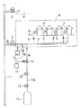
例えば、都市ガスは、この発明の一実施例を示す図1を参照して説明すると、幹線道路に埋設されたガス本管1から消費者群に供給用ガバナ2を介して導管3を分岐し、この分岐導管3から各家庭Hなどに引込管4、開閉弁5、消費メータ6などを介して供給される。
【0003】
このガス供給システムにおいて、ガス本管1は勿論のこと、分岐導管3及び引込み管4において、ガス洩れが生じていると、ガス爆発などの大事故を招く恐れがある。このため、従来から、そのガス洩れを検出するために種々の手段が採られている。
【0004】
その1つは、ボーリング調査と呼ばれ、道路下に埋設された導管3真上に深さ50cm程度の穴を穿き、その穴に管を挿入して、その部分の空気を吸引し、ガス検知器又は臭気で漏洩の有無を検査する方法であり、また、他の手段として、水素炎イオン化式ガス検知器等を用いて、路線上の地表近くの空気を吸引して漏洩の有無を検査する方法を採用したり、さらに、被検査部分へのガスの流入を遮断した後、所定の時間の圧力を測定して、その圧力変化により漏洩の有無を検査する方法を採用している。
【0005】
【発明が解決しようとする課題】
ボーリングは、約5mおきに穴を穿く為、道路に傷が付くと共に大変な労力と経費が必要であり、場所によっては穴を穿けることができないところも多々ある。水素炎イオン化式ガス検知器等の使用の方法は、天然ガス等の比重の小さいガス(空気より軽いガス)にのみ適用できる方法で、LPガス等の重いガスには使用できない。また、人間が入れない場所、例えば床下、パイプシャフト等の建家内の配管においては、使用できない。圧力保持式は、ガス消費を停止した後、実施する必要があり、消費者には検査する間の時間、ガスが使用できないと言った不便をかける。また、大規模な集団供給設備ではガスの停止と再開栓に膨大な手数がかかるばかりか、特に開栓時においてガス事故防止のための安全確認に細心の注意が必要となる。
【0006】
この発明は、都市ガス等のガス導管等の漏洩の有無を、深夜等のガスを消費しない時間帯を利用して、また、消費者にガス供給を停止する事なく無人で自動的に検査し得るようにすることを課題とする。
【0007】
【課題を解決するための手段】
上記課題を解決するために、この発明は、従来周知のガス本管から分岐導管及び引込管に一定圧(設定圧力)のガスを送り込んでガス管路における、前記ガス本管に接続された検査対象導管及び引込管を、前記ガス本管からガスを導入自在な状態で、例えば一定圧以下になれば、本管からガスが導入される状態で、ガス本管から供給される設定圧力より幾分高い圧力に維持し(加圧し)、一定時間、前記高い圧力が一定値以上低下しない場合、前記検査対象導管等に漏洩が生じていないと判断することとしたのである。
【0008】
一方、圧力低下が一定値以下になれば、再度、高い圧力に維持するようにし、一定期間、例えば1ヶ月間一度も前記の漏洩が生じていないと判断することが出来ない場合は、検査対象導管等に漏洩が生じている可能性があると判断する。
【0009】
このとき、本管からガス導入自在な状態としていることにより、高い圧力に維持しているときに、ガス消費が開始されて検査対象導管の圧力が低下しても、本管から自動的にガスが供給され、ガス消費に支障を来すことはない。
【0010】
【発明の実施の形態】
この発明の一実施形態としては、ガス本管に各消費者への分岐導管を逆止弁を介して接続し、その逆止弁以降の前記分岐導管に、前記ガス本管より高い圧力のガスを注入可能とするとともに、その分岐導管の圧力検出のためのガス圧検出器を設けた構成を採用でき、そのガス圧検出器の検出信号に基づき、高い圧力のガスを注入及び停止して、分岐導管をガス本管より高い圧力に維持しようとしているにもかかわらず、一定時間内に、その圧力が一定値以上低下すれば、その導管にはガス漏洩が生じていると判断して、適宜な措置を行う。
【0011】
分岐導管への高い圧力のガスの導入は、高圧のガスボンベなどからの検査用ガスを使用すればよく、その検査用ガスの導入開閉は、開閉弁で行うことができ、この開閉弁の開閉は、上記ガス圧検出器の検出信号によりコントローラでもって制御する。
【0012】
このとき、上記検査対象導管(分岐導管)を高い圧力に維持しようとしても、高い圧力にならない場合、その維持作用を停止し、一定時間の経過後、再度、その維持作用をして、漏洩検査を行うようにするとよい。高い圧力を維持できないのは、通常、大きな消費がある場合であり、この場合は、ガス消費が停止するまで、被検査対象導管のガス圧力は上昇することがなく、検査用ガスを浪費してしまうことになる。このため、開弁後、一定時間(通常、消費がなければ被検査対象導管の圧力が上昇する時間であって、5分間程度)が経過しても被検査対象導管のガス圧力が上昇しないときは、一旦、自動開閉弁を閉じた後、一定時間(通常、給湯等による一回当たりのガス消費時間であって15分程度)経過後、再度開弁するようにする。
【0013】
【実施例】
一実施例を図1に示し、この実施例は、前述のように、幹線道路に埋設されたガス本管1から消費者群に供給用ガバナ2を介して導管3を分岐し、この分岐導管3から各家庭Hなどに引込み管4、開閉弁5、消費メータ6などを介してガスbが供給される。前記供給用ガバナ2は、逆止弁機能(閉塞機能)を有して分岐導管3からガス本管1へのガス逆流を阻止しながら、ガス本管1からのガスbを一定値に減圧、例えば0.1MPaから2.0KPaに減圧して分岐導管3に送り込むものであり、少なくとも漏洩検査時にはガス消費に支障をきたさない範囲内で、分岐導管3内のガスが所要の圧力、例えば1.5〜2.0KPaとなるように設定する。
【0014】
上記分岐導管3に、検査用ガスボンベ11が減圧調整弁12、検査用ガバナ13、自動開閉弁(電磁弁)14を介設した検査用ガス管10が接続されており、ボンベ11には、ガス本管1からの供給ガスbと同一若しくは燃焼に支障のない類似ガスaが充填されている。このため、自動開閉弁14が開放すると、ボンベ11内の検査用ガスaが、減圧調整弁12により一定値、例えば10KPaに減圧され、さらにガバナ13により減圧、例えば2.5KPaに減圧されて分岐導管3に送り込まれ、このとき、その導入ガス圧はガス本管1からのガバナ2を介しての供給ガスbより高く設定されているため、分岐導管3は供給ガスbより高い圧力となる。
【0015】
また、分岐導管3には圧力記録装置15が付設され、この圧力記録装置は、分岐導管3の圧力測定を行ってその変化を記録する。さらに、分岐導管3には、圧力スイッチなどの外部出力付き圧力測定装置16が付設されており、自動開閉弁14が開き、検査用ガスaが導入され、分岐導管3の圧力が上昇して所定の圧力P1 (例えば2.4KPa)になると、その旨の信号を、また、自動開閉弁が閉じられ分岐導管3に洩れのある場合及びガス消費のある場合に圧力が低下し、所定の圧力P2 (例えば2.1KPa)まで低下すると、その旨の信号をコントローラ17にそれぞれ発信する。
【0016】
コントローラ17は、入力として外部出力付き圧力測定装置16からの信号を、出力として自動開閉弁14に開閉命令を出すものであり、外部出力付き圧力測定装置16から設定圧力P1 まで上昇した信号を受けると、自動開閉弁14に閉じる命令を、逆に設定圧力P2 まで低下した信号を受けると開く信号を発する。なお、自動開閉弁14を検査用ガバナ13の出口側に設置しているが、検査用ガバナ13の直近であればその上流にても差し支えはない。
【0017】
この実施例は以上の構成であり、図の鎖線枠で示す被検査対象導管範囲(供給用ガバナ2以降の導管3及び引込み管4)A毎にそれぞれ構成され、それぞれにおいて、コントローラ17より自動開閉弁14に開弁信号を発し、検査用ガスaを分岐導管3に導入する。所定の上限圧力(供給用ガバナの閉塞圧力より高い圧力であって、ガス消費に支障のない高い圧力)P1まで上昇すると、外部出力付き圧力測定装置16がコントローラ17にその旨を発信して、自動開閉弁14が閉じられる。自動開閉弁14が閉じられて分岐導管3に漏れのある場合及びガス消費のある場合には圧力が低下するが、所定の圧力P2まで低下すると、外部出力付き圧力測定装置16がコントローラ17にその旨を発信して、自動開閉弁14が再度開かれ、検査用ガスaが分岐導管3に導入される。以下、その繰り返しが行われる。
【0018】
この漏洩検査時に、検査用ガス側からのガス供給を越えるガス消費が発生した場合、供給用ガバナ2から自動的にガスが供給されてガス消費に支障は来さない。
【0019】
その間の圧力記録装置15によって記録された圧力変動を読み、一定時間(分岐導管3の容積が10m3以下であれば、通常5分間)上限圧力が低下することがない場合、漏洩がないものと判断する。一方、圧力低下が一定値以下になれば、上記検査対象導管等に漏洩が生じていると判断する。
【0020】
この検査時、コントローラ17に時計を内蔵し、タイマーにより、漏洩検査時間をガス消費の少ない時間帯(通常、深夜から未明にかけての時間帯)に限定して、検査用ガスaの浪費を減らす。また、開弁後、5分間程度が経過しても分岐導管3のガス圧力が上昇しないときは、一旦、自動開閉弁14を閉じた後、15分程度経過後、再度開弁する。さらに、圧力上昇後、ガス消費により圧力が低下した場合、即座に自動開閉弁14を開かず、15分経過後、開弁するようにして、検査用ガスaの浪費を減らす。
【0021】
以上の分岐導管3の圧力変化が圧力記録装置15に記録され、その記録により、その変化を読み取って漏洩有無の判断を行う。このとき、封入圧力及び経過時間を自動的に読み取り、所定の一定時間、例えば分岐導管3の容積が10m3 以下であれば、通常5分間、封入圧力に変化のない場合、その旨(漏洩が生じていない旨)をランプ等で表示することができる。
なお、一定期間、例えば1ヶ月間一度も上記の漏洩が生じていないと判断することが出来ない場合は、検査対象導管等に漏洩が生じている可能性があると判断する。
【0022】
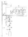
上記本管1のガス圧力が上記分岐導管3と等しい場合、分岐導管3の供給用ガバナ2に代えて、図2に示すように、逆止弁18を採用することができ、さらに、その逆止弁18に代えて圧力損失の小さい逆止機能を有する大口径のガバナを使用し得る。また、供給用ガバナ2の上流側の圧力(ガス本管1のガス圧)が所定の圧力P1 以上有れば、図3に示すように、その上流側の供給ガスbを検査用ガスaとして使用できる。さらに、図4に示すように、供給ガスbの圧力が所定圧力P1 以下の場合でも、ブースタ19を介し昇圧して設定圧P1 とし、検査用ガスaとして使用し得る。また、図1において、検査用ガスボンベ11に代えて移動式ガス発生設備も使用し得る。
【0023】
なお、分岐導管3の容積が小さい場合など、自動開閉弁14の追従遅れにより、分岐導管3の圧力が所定の圧力を越えることが考えられる。このため、検査用ガバナ13と分岐導管3の途中に定流量弁又は絞りを設けて、検査用ガバナ13から分岐導管3に導入されるガス量の制限を行って、その追従遅れを補償するとよい。また、外部出力付き圧力測定装置16が設定圧力に達したとき、その旨をコントローラ17に発したが、圧力センサを検査対象導管3等に取りつけ、コントローラ17がその圧力を読み取って設定圧力の判断を自動的に行うようにすることができる。圧力検出器(圧力測定装置)16は検出用ガス管10の自動開閉弁14から導管3までの間に付設することもできる。
【0024】
【発明の効果】
この発明は、以上のように、本来のガス供給をしながら、検査対象導管の圧力変化によって、漏洩を検出するようにしたので、▲1▼消費者のガス消費を停止させる必要がない、▲2▼装置をセットしておけば、無人で検査がされる、▲3▼人の入れないところも確実に検査ができる、▲4▼軽いガスでも重いガスでも使用できる、などの効果がある。
【図面の簡単な説明】
【図1】一実施例のガス検査回路図
【図2】他の実施例のガス検査回路図
【図3】他の実施例のガス検査回路図
【図4】他の実施例のガス検査回路図
【符号の説明】
1 ガス本管
2 供給用ガバナ
3 検査対象導管(分岐導管)
4 引込み管
5 開閉弁
6 消費メータ
10 検査用ガス管
11 検査用ガスボンベ
12 減圧調整弁
13 検査用ガバナ
14 自動開閉弁
15 圧力記録装置
16 圧力測定装置
17 コントローラ
18 逆止弁
19 ブースタ
a 検査用ガス
b 供給ガス
H 家庭[0001]
BACKGROUND OF THE INVENTION
The present invention relates to a method and an apparatus for detecting leakage of a gas conduit such as the conduit in a system in which a conduit is connected to a gas main and gas is supplied to each consumer from the conduit.
[0002]
[Prior art]
For example, city gas will be described with reference to FIG. 1 showing an embodiment of the present invention. A gas main 1 embedded in a main road branches a
[0003]
In this gas supply system, if a gas leak occurs in the
[0004]
One of them is called boring survey. A hole with a depth of about 50cm is drilled just above the
[0005]
[Problems to be solved by the invention]
Boring drills holes every 5 meters, which can damage the road and require a lot of labor and cost. There are many places where it is impossible to drill holes depending on the location. The method of using a hydrogen flame ionization gas detector or the like is a method that can be applied only to a gas having a small specific gravity such as natural gas (gas lighter than air) and cannot be used for a heavy gas such as LP gas. Moreover, it cannot be used in places where humans cannot enter, for example, piping in buildings such as under the floor and pipe shafts. The pressure holding type needs to be implemented after the gas consumption is stopped, and the consumer is inconvenienced that the gas cannot be used for the time during the inspection. In addition, large-scale collective supply facilities not only require enormous effort to stop and restart the gas, but also require careful attention to confirm safety to prevent gas accidents, particularly when the gas is opened.
[0006]
The present invention automatically and unmannedly checks for leaks in city gas and other gas conduits, etc., using a time zone during which no gas is consumed, such as at midnight, and without stopping the gas supply to the consumer. The problem is to get it.
[0007]
[Means for Solving the Problems]
In order to solve the above-described problems, the present invention is directed to inspecting a gas pipe line connected to the gas main pipe by feeding a constant pressure (set pressure) from a conventionally known gas main pipe to the branch pipe and the lead-in pipe. If the target pipe and the lead-in pipe are in a state where gas can be freely introduced from the gas main pipe, for example, if the pressure is reduced to a certain pressure or less, the gas is introduced from the main pipe and the set pressure supplied from the gas main pipe is increased. When the pressure is kept high (pressurized) for a certain period and the high pressure does not decrease over a certain value for a certain period of time, it is determined that there is no leakage in the inspected conduit or the like.
[0008]
On the other hand, if the pressure drop falls below a certain value, the pressure is maintained again, and if it is not possible to determine that the leakage has not occurred for a certain period of time, for example once a month, Judge that there is a possibility of leakage in the conduit.
[0009]
At this time, since the gas can be introduced from the main, the gas is automatically discharged from the main even if the gas consumption starts and the pressure of the pipe to be inspected decreases while maintaining a high pressure. Will not interfere with gas consumption.
[0010]
DETAILED DESCRIPTION OF THE INVENTION
As one embodiment of the present invention, a branch conduit to each consumer is connected to a gas main through a check valve, and a gas having a pressure higher than that of the gas main is connected to the branch conduit after the check valve. Can be injected, and a configuration provided with a gas pressure detector for detecting the pressure of the branch conduit can be adopted. Based on the detection signal of the gas pressure detector, high pressure gas is injected and stopped, Despite trying to maintain the branch conduit at a higher pressure than the gas main, if the pressure drops below a certain value within a certain period of time, it is determined that the conduit is leaking gas and Take appropriate measures.
[0011]
The introduction of high-pressure gas into the branch conduit may be performed by using inspection gas from a high-pressure gas cylinder, etc. The inspection gas can be opened and closed by an on-off valve. The controller controls the detection signal of the gas pressure detector.
[0012]
At this time, even if trying to maintain the above-mentioned inspection target pipe (branch pipe) at a high pressure, if the pressure does not become high, the maintenance action is stopped, and after a certain period of time, the maintenance action is performed again, and a leak inspection is performed. It is good to do. The high pressure cannot usually be maintained when there is a large consumption, in which case the gas pressure in the pipe to be inspected does not increase until the gas consumption stops, and the gas for inspection is wasted. Will end up. For this reason, after the valve is opened, the gas pressure in the inspected conduit does not increase after a certain period of time (usually, if there is no consumption, the pressure in the inspected conduit rises for about 5 minutes) In this case, once the automatic opening / closing valve is closed, the valve is opened again after a certain period of time (usually about 15 minutes for gas consumption per hot water supply).
[0013]
【Example】
An embodiment is shown in FIG. 1, which, as described above, branches a
[0014]
An
[0015]
Further, a
[0016]
The
[0017]
This embodiment has the above-described configuration, and is configured for each of the inspected conduit ranges (
[0018]
If gas consumption exceeding the gas supply from the inspection gas side occurs during this leakage inspection, the gas is automatically supplied from the
[0019]
The pressure fluctuation recorded by the
[0020]
At the time of this inspection, a clock is built in the
[0021]
The pressure change in the
In addition, when it cannot be determined that the above leakage has not occurred even for a certain period of time, for example, one month, it is determined that there is a possibility that leakage has occurred in the inspection target conduit or the like.
[0022]
When the gas pressure of the
[0023]
In addition, when the volume of the
[0024]
【The invention's effect】
According to the present invention, as described above, since the leakage is detected by the pressure change of the inspection target conduit while supplying the original gas, (1) it is not necessary to stop the consumer's gas consumption. 2) If the device is set, there is an effect such that inspection can be performed unattended, (3) it can be surely inspected where no one can enter, and (4) light or heavy gas can be used.
[Brief description of the drawings]
FIG. 1 is a gas inspection circuit diagram of another embodiment. FIG. 2 is a gas inspection circuit diagram of another embodiment. FIG. 3 is a gas inspection circuit diagram of another embodiment. Figure [Explanation of symbols]
1 Gas main 2 Governor for
4 Lead-in
Claims (4)
上記分岐導管(3)に、検査用ガス管(10)を開閉弁(14)を介して接続するとともにガス圧検出器(16)を設け、そのガス圧検出器(16)からの検出信号により前記開閉弁(14)の開閉をコントローラ(17)でもって制御し、上記消費者のガス消費が少ない時間帯において、上記開閉弁(14)を開放して、上記逆止弁以降の分岐導管(3)及び引込管(4)にガス消費に支障が生じない範囲内の上記一定圧より高い圧力のガス(a)を送り込んで、その分岐導管(3)及び引込管(4)内を、前記ガス本管(1)からガス(b)を導入自在な状態でガス本管(1)から供給される前記一定圧より幾分高い圧力(P 1 )に加圧して前記開閉弁(14)を閉じてその高い圧力(P 1 )を維持し、前記ガス圧検出器(16)でもって前記一定圧の低下の有無に基づく漏洩検査を行い、
その漏洩検査において、一定時間、前記高い圧力が一定値以上低下しない場合、上記分岐導管(3)及び引込管(4)に漏洩が生じていないとし、一方、前記高い圧力(P 1 )が一定値以上低下した場合、前記漏洩が生じているとし、
上記分岐導管(3)及び引込管(4)を上記高い圧力(P 1 )に加圧した後に、消費者のガス消費が多くてその高い圧力(P 1 )が維持できない場合、又は、前記高い圧力(P 1 )に加圧できない場合、一定時間の経過後、再度、前記高い圧力(P 1 )への加圧作用をして漏洩検査を行うようにしたことを特徴とするガス導管漏洩検知方法。Connected to the gas main (1) through a branch valve (3) to each consumer via a check valve (2, 18) that prevents gas backflow from the branch conduit (3) to the gas main (1) Then, each consumer's lead-in pipe (4) is connected to the branch pipe (3) after the check valve, and from the gas main pipe (1) to the branch pipe (3) and the lead-in pipe (4). A gas conduit leakage detection method for a branch conduit (3) and a lead-in tube (4) after the check valve in a gas conduit for feeding gas under pressure ,
An inspection gas pipe (10) is connected to the branch conduit (3) via an on-off valve (14), and a gas pressure detector (16) is provided, and a detection signal from the gas pressure detector (16) is provided. The controller (17) controls the opening and closing of the on- off valve (14), and the on-off valve (14) is opened in a time zone in which the consumer consumes less gas. 3) and a gas (a) having a pressure higher than the above-mentioned constant pressure within a range that does not impede gas consumption into the inlet pipe (4), and the inside of the branch pipe (3) and the inlet pipe (4) The open / close valve (14) is pressurized by pressurizing the gas (b) from the gas main (1) to a pressure (P 1 ) somewhat higher than the constant pressure supplied from the gas main (1) in a state where the gas (b) can be introduced freely. Close and maintain its high pressure (P 1 ), even with the gas pressure detector (16) And perform a leak inspection based on the presence or absence of a decrease in the constant pressure,
In that leakage inspection, if the predetermined time, it does not decrease the high pressure than a predetermined value, a leak in the upper Symbol branch line (3) and lead-in tube (4) does not occur, whereas, the high pressure (P 1) is If it falls below a certain value, the leakage is occurring,
After pressurized to the branch conduit (3) and lead-in tube (4) the high pressure (P 1), if it is more gas consumption of consumer its high pressure (P 1) can not be maintained, or, the high If you can not pressurized to a pressure (P 1), after a certain time, once again, the high pressure by the pressure effect it has to perform leak test gas conduit leak detection, wherein the (P 1) to Method.
Priority Applications (1)
| Application Number | Priority Date | Filing Date | Title |
|---|---|---|---|
| JP30434698A JP4139908B2 (en) | 1998-10-26 | 1998-10-26 | Gas conduit leak detection method and detection apparatus |
Applications Claiming Priority (1)
| Application Number | Priority Date | Filing Date | Title |
|---|---|---|---|
| JP30434698A JP4139908B2 (en) | 1998-10-26 | 1998-10-26 | Gas conduit leak detection method and detection apparatus |
Publications (3)
| Publication Number | Publication Date |
|---|---|
| JP2000131183A JP2000131183A (en) | 2000-05-12 |
| JP2000131183A5 JP2000131183A5 (en) | 2005-11-10 |
| JP4139908B2 true JP4139908B2 (en) | 2008-08-27 |
Family
ID=17931916
Family Applications (1)
| Application Number | Title | Priority Date | Filing Date |
|---|---|---|---|
| JP30434698A Expired - Lifetime JP4139908B2 (en) | 1998-10-26 | 1998-10-26 | Gas conduit leak detection method and detection apparatus |
Country Status (1)
| Country | Link |
|---|---|
| JP (1) | JP4139908B2 (en) |
Families Citing this family (3)
| Publication number | Priority date | Publication date | Assignee | Title |
|---|---|---|---|---|
| JP3798252B2 (en) * | 2001-03-22 | 2006-07-19 | 東京瓦斯株式会社 | Gas pipe leak inspection method and leak inspection apparatus |
| KR101252155B1 (en) * | 2011-03-17 | 2013-04-12 | 송해청 | System device for detecting leaking conduit |
| CN113720552A (en) * | 2021-08-13 | 2021-11-30 | 中山港华燃气有限公司 | Method for detecting leakage of commercial complex gas matching pipeline |
-
1998
- 1998-10-26 JP JP30434698A patent/JP4139908B2/en not_active Expired - Lifetime
Also Published As
| Publication number | Publication date |
|---|---|
| JP2000131183A (en) | 2000-05-12 |
Similar Documents
| Publication | Publication Date | Title |
|---|---|---|
| CA1091988A (en) | Leak detecting apparatus | |
| BE1017016A5 (en) | Gas leak determining method for e.g. convector, involves connecting distribution system or system`s part to suite or device with control unit interrupting gas supply when gas quantity is greater or equal to quantity filling buffer chamber | |
| JP4139908B2 (en) | Gas conduit leak detection method and detection apparatus | |
| KR101013959B1 (en) | Hydrogen gas leakage detection device of fuel cell vehicle and method thereof | |
| CN209655043U (en) | A kind of low-pressure fuel gas pipeline minute leakage on-line monitoring system | |
| JP2001108569A (en) | Method for measuring content volume of gas supply line and leak volume, and device therefor | |
| JP2002333381A (en) | Detection method for leak of hydrogen gas | |
| CN109708004A (en) | A kind of low-pressure fuel gas pipeline minor leakage on-line monitoring system and method | |
| JPH08128914A (en) | Leak detection device | |
| JP2817875B2 (en) | Gas leak monitoring system | |
| JPH0886713A (en) | Piping leakage detecting device | |
| CN217953797U (en) | Gas heat treatment furnace pipeline leak detection system | |
| JPH11351444A (en) | Leakage of gas control valve inspection method and device | |
| KR0120723Y1 (en) | Apparatus for checking of bagfilter | |
| JP2713066B2 (en) | Gas supply equipment abnormality detector | |
| JPH0799348B2 (en) | Gas micro leak monitoring method, gas micro leak monitoring system, and gas distributor for gas micro leak monitoring system | |
| JPH09242139A (en) | Leakage testing method and hydraulic testing machine | |
| JP2006328958A (en) | Fuel supply device and fuel supply detecting method of independent power generating set | |
| JP2001174359A (en) | Leakage inspecting method for buried lp gas pipe and its device | |
| JPH082589Y2 (en) | Gas micro leak monitor | |
| JPS63134931A (en) | Method for detecting leakage of double safety shut off valve | |
| JP2015212714A (en) | Leak detection method and device | |
| JPH0124612Y2 (en) | ||
| JPH09119883A (en) | Method and system for monitoring minute leak of gas | |
| JP2004239047A (en) | Emergency water storage securement function attached water storage tank |
Legal Events
| Date | Code | Title | Description |
|---|---|---|---|
| A521 | Written amendment |
Free format text: JAPANESE INTERMEDIATE CODE: A523 Effective date: 20050928 |
|
| A621 | Written request for application examination |
Free format text: JAPANESE INTERMEDIATE CODE: A621 Effective date: 20050928 |
|
| A977 | Report on retrieval |
Free format text: JAPANESE INTERMEDIATE CODE: A971007 Effective date: 20070629 |
|
| A131 | Notification of reasons for refusal |
Free format text: JAPANESE INTERMEDIATE CODE: A131 Effective date: 20070710 |
|
| A521 | Written amendment |
Free format text: JAPANESE INTERMEDIATE CODE: A523 Effective date: 20070907 |
|
| A131 | Notification of reasons for refusal |
Free format text: JAPANESE INTERMEDIATE CODE: A131 Effective date: 20071211 |
|
| A521 | Written amendment |
Free format text: JAPANESE INTERMEDIATE CODE: A523 Effective date: 20080208 |
|
| TRDD | Decision of grant or rejection written | ||
| A01 | Written decision to grant a patent or to grant a registration (utility model) |
Free format text: JAPANESE INTERMEDIATE CODE: A01 Effective date: 20080408 |
|
| A01 | Written decision to grant a patent or to grant a registration (utility model) |
Free format text: JAPANESE INTERMEDIATE CODE: A01 |
|
| A711 | Notification of change in applicant |
Free format text: JAPANESE INTERMEDIATE CODE: A711 Effective date: 20080514 |
|
| A61 | First payment of annual fees (during grant procedure) |
Free format text: JAPANESE INTERMEDIATE CODE: A61 Effective date: 20080519 |
|
| A521 | Written amendment |
Free format text: JAPANESE INTERMEDIATE CODE: A821 Effective date: 20080514 |
|
| FPAY | Renewal fee payment (event date is renewal date of database) |
Free format text: PAYMENT UNTIL: 20110620 Year of fee payment: 3 |
|
| R150 | Certificate of patent or registration of utility model |
Free format text: JAPANESE INTERMEDIATE CODE: R150 |
|
| FPAY | Renewal fee payment (event date is renewal date of database) |
Free format text: PAYMENT UNTIL: 20110620 Year of fee payment: 3 |
|
| FPAY | Renewal fee payment (event date is renewal date of database) |
Free format text: PAYMENT UNTIL: 20120620 Year of fee payment: 4 |
|
| FPAY | Renewal fee payment (event date is renewal date of database) |
Free format text: PAYMENT UNTIL: 20130620 Year of fee payment: 5 |
|
| FPAY | Renewal fee payment (event date is renewal date of database) |
Free format text: PAYMENT UNTIL: 20130620 Year of fee payment: 5 |
|
| R250 | Receipt of annual fees |
Free format text: JAPANESE INTERMEDIATE CODE: R250 |
|
| R250 | Receipt of annual fees |
Free format text: JAPANESE INTERMEDIATE CODE: R250 |
|
| R250 | Receipt of annual fees |
Free format text: JAPANESE INTERMEDIATE CODE: R250 |
|
| R250 | Receipt of annual fees |
Free format text: JAPANESE INTERMEDIATE CODE: R250 |
|
| R250 | Receipt of annual fees |
Free format text: JAPANESE INTERMEDIATE CODE: R250 |
|
| R250 | Receipt of annual fees |
Free format text: JAPANESE INTERMEDIATE CODE: R250 |
|
| EXPY | Cancellation because of completion of term |