JP4139843B2 - Sewing machine threading device - Google Patents
Sewing machine threading device Download PDFInfo
- Publication number
- JP4139843B2 JP4139843B2 JP2007014450A JP2007014450A JP4139843B2 JP 4139843 B2 JP4139843 B2 JP 4139843B2 JP 2007014450 A JP2007014450 A JP 2007014450A JP 2007014450 A JP2007014450 A JP 2007014450A JP 4139843 B2 JP4139843 B2 JP 4139843B2
- Authority
- JP
- Japan
- Prior art keywords
- threading
- shaft
- cam
- needle
- thread
- Prior art date
- Legal status (The legal status is an assumption and is not a legal conclusion. Google has not performed a legal analysis and makes no representation as to the accuracy of the status listed.)
- Active
Links
Images


Classifications
-
- D—TEXTILES; PAPER
- D05—SEWING; EMBROIDERING; TUFTING
- D05B—SEWING
- D05B87/00—Needle- or looper- threading devices
- D05B87/02—Needle- or looper- threading devices with mechanical means for moving thread through needle or looper eye
-
- D—TEXTILES; PAPER
- D05—SEWING; EMBROIDERING; TUFTING
- D05D—INDEXING SCHEME ASSOCIATED WITH SUBCLASSES D05B AND D05C, RELATING TO SEWING, EMBROIDERING AND TUFTING
- D05D2205/00—Interface between the operator and the machine
- D05D2205/02—Operator to the machine
Description
本発明は、針棒に近接した1本の糸通し軸を下降及び回動させることにより、糸通し軸の下端部に付設した鉤部により針穴への糸通しを行うミシンの糸通し装置に関する。 The present invention relates to a threading device for a sewing machine in which a threading shaft adjacent to a needle bar is lowered and rotated to thread a needle hole with a collar attached to a lower end portion of the threading shaft. .
従来、ミシンを用いて加工布に縫目を形成する縫製作業に当たり、縫針の針穴に簡単に糸通しすることが可能な糸通し装置を装備したミシンが実用に供されている(特許文献1及び2参照)。例えば特許文献1では、操作者が糸通しレバーを下降させた場合、糸通し軸とスライダーガイド軸とが下降し、糸通し軸の上端部の摺動ピンが針棒側の係止部に当接した段階でこれら糸通し軸とスライダーガイド軸との高さ位置が規制される。その後さらに糸通しレバーを下降させた場合、摺動ピンを備えた糸通し軸が、摺動ピンを含むカム機構により所定角度だけ回動して、糸通し軸の下端部に付設のフックを針穴に挿通させた後、糸通しが実行される。 2. Description of the Related Art Conventionally, a sewing machine equipped with a threading device that can be easily threaded through a needle hole of a sewing needle has been put to practical use in sewing work for forming a stitch on a work cloth using a sewing machine (Patent Document 1). And 2). For example, in Patent Document 1, when the operator lowers the threading lever, the threading shaft and the slider guide shaft descend, and the sliding pin on the upper end of the threading shaft contacts the locking portion on the needle bar side. At the stage of contact, the height positions of the threading shaft and the slider guide shaft are regulated. Thereafter, when the threading lever is further lowered, the threading shaft provided with the sliding pin is rotated by a predetermined angle by the cam mechanism including the sliding pin, and the hook attached to the lower end of the threading shaft is needled. After threading through the hole, threading is performed.
しかし、特許文献1では、手動でフックに糸をかける必要があり、操作者は両手を用いて糸通し作業を行う必要があるという問題点があった。そこで特許文献2では、糸駒から提供される上糸をミシンの所定の位置に糸掛けしておき、操作者が糸通しレバーを下降させた場合、糸通し軸の上端部の摺動ピンが針棒側の係止部に当接した段階でこれら糸通し軸とスライダーガイド軸の高さ位置が規制される。
However, in Patent Document 1, it is necessary to manually thread the hook, and there is a problem that the operator needs to perform threading work using both hands. Therefore, in
その後さらに糸通しレバーを下降させた場合、摺動ピンを備えた糸通し軸が、摺動ピンを含むカム機構により所定角度だけ回動して、糸通し軸の下端部に付設のフックを針穴に挿通させる。フックは、針穴に挿通した状態で、糸掛けしてある上糸を引っ掛け、糸通しレバーを上昇させた場合にフックが針穴から抜け出るのに応じて糸通しが実行される。このように、操作者は、糸通しレバーを下降、上昇させる動作のみで糸通しを実行することができる。
しかし、特許文献2では、特許文献2の図5及び図7を参照すれば明らかなように、針棒のほか、糸通し軸の下端部に固着されているフック機構の動作を制御し、上糸を確実に糸通しするために、糸通し軸とスライダーガイド軸との2本の操作軸が必要となっている。したがって、ミシンの針棒を含めたヘッド部分の慣性が大きく、ジグザグ縫い等の動きの細かい作業を行う場合に高速化が困難になるという問題点があった。
However, in
また、部品点数が多くなることから、ヘッド部全体をコンパクトにすることが困難になるとともに、低コスト化することも困難になるという問題点もあった。 In addition, since the number of parts increases, it is difficult to make the entire head part compact, and it is also difficult to reduce the cost.
本発明は斯かる事情に鑑みてなされたものであり、ヘッド部全体をコンパクト化することができるとともに、操作者が片手で確実に糸通し作業を実行することができるミシンの糸通し装置を提供することを目的とする。 The present invention has been made in view of such circumstances, and provides a threading device for a sewing machine in which the entire head portion can be made compact and the operator can reliably perform the threading operation with one hand. The purpose is to do.
上記目的を達成するために第1発明に係るミシンの糸通し装置は、支持している縫針を上下に移動させる針棒に近接し、上下に移動することが可能であり、しかも軸を中心として回転することが可能に支持されている糸通し軸と、前記糸通し軸の下端部に固着され、縫針の針穴に挿通することが可能な鉤部と、該鉤部を針穴に誘導する第1のガイド部とを有する糸通しフックと、前記糸通し軸の下降限界位置を、前記鉤部と縫針の針穴との高さが一致する位置に規制する位置決め部材と、前記糸通し軸の下降限界点近傍で前記鉤部が縫針の針穴に挿通するよう前記第1のガイド部を所定角度回動させる第1の回動機構と、前記糸通し軸の下降限界点近傍で前記鉤部まで上糸を誘導する糸誘導部材とを備えるミシンの糸通し装置において、前記糸誘導部材は、糸を引っ掛ける糸引っかかり部と、該糸引っかかり部を縫針方向へ誘導する第2のガイド部とを有し、前記糸通し軸の下降限界点近傍で前記糸引っかかり部が縫針の位置を越えて縫針と交差するよう前記第2のガイド部を所定角度回動させる第2の回動機構を備え、前記第1の回動機構及び前記第2の回動機構は、前記糸通しフック及び前記糸誘導部材を互いに反対方向に回転させ、前記糸通し軸に外嵌又は内嵌されてミシン本体に固着されており、周面に第1のカム穴及び第2のカム穴を有する糸通し案内部材を有し、前記第1の回動機構は、前記第1のカム穴、及び前記糸通し軸に設けてある、前記第1のカム穴に嵌合する第1のカム軸を備え、前記第2の回動機構は、前記第2のカム穴、及び前記糸誘導部材に設けてある、前記第2のカム穴に嵌合する第2のカム軸を備え、前記第1のカム穴の傾斜方向と、前記第2のカム穴の傾斜方向とが反対方向となるようにしてあり、前記第1のカム穴の最上部近傍での上下方向の幅は、前記第1のカム軸の軸径よりも大きくなるようにしてあり、前記糸通しフックと前記糸誘導部材との間に、前記糸通しフックと前記糸誘導部材とを離隔させるよう付勢する付勢部材を備えることを特徴とする。 In order to achieve the above object, the threading device for a sewing machine according to the first aspect of the present invention is capable of moving up and down close to a needle bar for moving a supported sewing needle up and down, and centering on an axis. A threading shaft supported so as to be rotatable, a collar fixed to a lower end portion of the threading shaft and capable of being inserted into a needle hole of a sewing needle, and guiding the collar to the needle hole A threading hook having a first guide portion, a positioning member that regulates a lowering limit position of the threading shaft to a position where the heights of the collar portion and the needle hole of the sewing needle coincide, and the threading shaft A first turning mechanism for turning the first guide part by a predetermined angle so that the collar part is inserted into the needle hole of the sewing needle in the vicinity of the lowering limit point of the thread, and the hooking part in the vicinity of the lowering limit point of the threading shaft. A threading device for a sewing machine comprising a thread guiding member for guiding an upper thread to a portion, Induction member has a yarn catching unit hooking the thread, and a second guide portion for inducing yarn catching section to the sewing needle direction, the position of the yarn catching section sewing needle in lowering limit near the point of the threading shaft A second rotation mechanism that rotates the second guide portion by a predetermined angle so as to cross the sewing needle beyond the sewing needle, and the first rotation mechanism and the second rotation mechanism include the threading hook. The thread guide member is rotated in opposite directions, and is fitted to the sewing machine body by being externally or internally fitted to the threading shaft, and has a first cam hole and a second cam hole on the peripheral surface. The first turning mechanism includes a first cam shaft that is provided in the first cam hole and the threading shaft, and that is fitted in the first cam hole. The second rotation mechanism is provided in the second cam hole and the thread guide member. A second camshaft that fits into the second cam hole, wherein the inclined direction of the first cam hole and the inclined direction of the second cam hole are opposite to each other, The vertical width in the vicinity of the uppermost portion of the first cam hole is larger than the shaft diameter of the first cam shaft, and between the threading hook and the thread guiding member, An urging member that urges the threading hook and the thread guiding member to be separated from each other is provided .
また、第2発明に係るミシンの糸通し装置は、第1発明において、前記糸通し軸を操作する、上下に移動することが可能な操作体を備えることを特徴とする。 Also, threading the sewing machine according to the second inventive device, in the first shot bright, operating the threading shaft, characterized in that it comprises an operation member capable of moving up and down.
第1発明では、支持している縫針を上下に移動させる針棒に近接する位置に、上下に移動することが可能であり、しかも軸を中心として回転することが可能に支持されている糸通し軸を1本備えている。糸通し軸の下端部には、縫針の針穴に挿通することが可能な鉤部と、該鉤部を針穴に誘導する第1のガイド部とを有する糸通しフックが装着されている。第1の回動機構は、糸通し軸の下降限界点近傍で鉤部が縫針の針穴に挿通するよう第1のガイド部を所定角度回動させる。糸誘導部材は、糸引っかかり部を縫針方向へ回転誘導し、第2の回動機構は、糸通し軸の下降限界点近傍で糸引っかかり部が縫針の位置を越えて縫針と交差するよう第2のガイド部を所定角度回動させる。第1の回動機構による糸通しフックの回転方向と、第2の回動機構による糸誘導部材の回転方向とは互いに反対方向であり、1本の糸通し軸の上下動により、縫針の針穴に挿通することが可能な鉤部と糸を引っ掛ける糸引っかかり部とを接近させたり離隔させたりすることができる。これにより、第2のガイド部と一体となって回転する糸引っかかり部に上糸を引っ掛けておき、第1のガイド部と一体となって回転する鉤部が針穴に挿入された後、鉤部へ上糸が引っかかる。鉤部が針穴から引き戻されるのに伴って、上糸が針穴へ挿入される。したがって、1本の糸通し軸の上下動に応じて確実に糸通しを実行することができ、ヘッド部全体をコンパクト化することができるとともに、低コスト化を図ることが可能となる。また、細かい動きが要求される縫製時であっても、移動部分の慣性が小さいことから、縫製精度を維持するために縫製速度を減じる必要が無い。 In the first invention, the threader is supported so that it can be moved up and down to a position close to the needle bar for moving the supported sewing needle up and down and can rotate around the shaft. One shaft is provided. A threading hook having a hook part that can be inserted into the needle hole of the sewing needle and a first guide part that guides the hook part to the needle hole is attached to the lower end part of the threading shaft. The first rotation mechanism rotates the first guide portion by a predetermined angle so that the collar portion is inserted into the needle hole of the sewing needle near the lowering limit point of the threading shaft. The thread guiding member rotates and guides the thread catching part in the direction of the sewing needle, and the second rotation mechanism is configured to cause the thread catching part to cross the sewing needle beyond the position of the sewing needle near the lowering limit point of the threading shaft. The guide portion is rotated by a predetermined angle. The rotation direction of the threading hook by the first rotation mechanism and the rotation direction of the thread guide member by the second rotation mechanism are opposite to each other, and the needle of the sewing needle is moved up and down by one threading shaft. The hook part that can be inserted into the hole and the thread catching part that hooks the thread can be brought close to or separated from each other. As a result, after the upper thread is hooked on the thread catching part that rotates integrally with the second guide part, and the hook part that rotates integrally with the first guide part is inserted into the needle hole, The upper thread is caught on the part. As the heel portion is pulled back from the needle hole, the upper thread is inserted into the needle hole. Therefore, the threading can be reliably executed according to the vertical movement of one threading shaft, the entire head portion can be made compact, and the cost can be reduced. Further, even during sewing that requires fine movement, since the inertia of the moving part is small, there is no need to reduce the sewing speed in order to maintain the sewing accuracy.
加えて、糸通し軸に外嵌又は内嵌されてミシン本体に固着されており、周面に第1のカム穴及び第2のカム穴を有する糸通し案内部材を有している。第1の回動機構は、第1のカム穴、及び糸通し軸に設けてある、第1のカム穴に嵌合する第1のカム軸とで構成され、第2の回動機構は、第2のカム穴、及び糸誘導部材に設けてある、第2のカム穴に嵌合する第2のカム軸とで構成されている。第1のカム穴の傾斜方向は、第2のカム穴の傾斜方向と反対方向としてあり、第1の回動機構が糸通し軸を中心として時計回り(反時計回り)に回転する場合、第2の回動機構は糸通し軸を中心として反時計回り(時計回り)に回転する。これにより、1本の糸通し軸の上下動により、上糸を誘導する糸引っかかり部と、針穴へ糸通しする鉤部との相対的な回転動作を制御することができ、確実に糸通しを実行することが可能となる。したがって、ヘッド部全体をコンパクト化することができるとともに、低コスト化を図ることが可能となる。
In addition, it has a threading guide member that is externally or internally fitted to the threading shaft and is fixed to the sewing machine body, and has a first cam hole and a second cam hole on the peripheral surface. The first rotation mechanism is composed of a first cam hole and a first cam shaft that is provided in the threading shaft, and is fitted in the first cam hole. The second cam hole and the second cam shaft provided in the yarn guiding member and fitted in the second cam hole are configured. The inclination direction of the first cam hole is opposite to the inclination direction of the second cam hole, and when the first rotation mechanism rotates clockwise (counterclockwise) about the threading shaft, The
さらに、第1のカム穴の最上部近傍での上下方向の幅は、第1のカム軸の軸径よりも大きくなるようにしてある。したがって、第2のガイド部、すなわち上糸を引っかけてある糸引っかかり部を、第1のガイド部、すなわち糸通しする鉤部の回転が止まった後にさらに下方へ移動させることができる。また、糸通しフックと糸誘導部材との間に、糸通しフックと糸誘導部材とを離隔させるよう付勢する付勢部材、例えばバネ等を備えることにより、鉤部が針穴から抜け出る前に糸誘導部材を元の位置、すなわち上糸を鉤部に引っかけることができる位置まで移動させることができる。したがって、例えば糸引っかかり部を糸通しフックより下降させた状態で鉤部を針穴に挿入し、鉤部が針穴から抜け出る前に糸引っかかり部を押し上げることで、鉤部に上糸が確実に引っかけられた状態で鉤部を針穴から引き出すことができ、確実に糸通しすることが可能となる。 Further, the vertical width in the vicinity of the uppermost portion of the first cam hole is made larger than the shaft diameter of the first cam shaft. Accordingly, the second guide portion, that is, the yarn hooking portion on which the upper thread is hooked can be moved further downward after the rotation of the first guide portion, that is, the hook portion through which the thread is passed. Further, by providing an urging member that urges the threading hook and the thread guiding member to be separated from each other, such as a spring, between the threading hook and the thread guiding member, before the collar portion comes out of the needle hole. The thread guiding member can be moved to the original position, that is, the position where the upper thread can be hooked on the collar. Therefore, for example, by inserting the collar into the needle hole with the thread catching part lowered from the threading hook, and pushing the thread catching part up before the collar comes out of the needle hole, The hook part can be pulled out from the needle hole in the hooked state, and the threading can be reliably performed.
第2発明では、糸通し軸を操作する、上下に移動することが可能な操作体を備える。操作者は、操作体を上下動することにより糸通し軸を上下動及び回動させることができ、片手で糸通し作業を行うことが可能となる。 In the second invention, an operating body that operates the threading shaft and is movable up and down is provided. The operator can move the threading shaft up and down by moving the operating body up and down, and can perform the threading operation with one hand.
第1発明によれば、第1の回動機構による第1のガイド部の回転方向と、第2の回動機構による第2のガイド部の回転方向は互いに反対方向であり、1本の糸通し軸の上下動により、縫針の針穴に挿通することが可能な鉤部と糸を引っかける糸引っかかり部とを接近させたり離隔させたりすることができる。これにより、第2のガイド部と一体となって回転する糸引っかかり部に上糸を引っ掛けておき、第1のガイド部と一体となって回転する鉤部が針穴に挿入された後、鉤部へ上糸が引っかかる。鉤部が針穴から引き戻されるのに伴って、上糸が針穴へ挿入される。したがって、1本の糸通し軸の上下動に応じて確実に糸通しを実行することができ、ヘッド部全体をコンパクト化することができるとともに、低コスト化を図ることが可能となる。また、細かい動きが要求される縫製時であっても、移動部分の慣性が小さいことから、縫製精度を維持するために縫製速度を減じる必要が無い。 According to the first invention, the rotation direction of the first guide portion by the first rotation mechanism and the rotation direction of the second guide portion by the second rotation mechanism are opposite to each other, and one yarn By the vertical movement of the threading shaft, the hook portion that can be inserted into the needle hole of the sewing needle and the thread catching portion that hooks the thread can be brought close to or separated from each other. As a result, after the upper thread is hooked on the thread catching part that rotates integrally with the second guide part, and the hook part that rotates integrally with the first guide part is inserted into the needle hole, The upper thread is caught on the part. As the heel portion is pulled back from the needle hole, the upper thread is inserted into the needle hole. Therefore, the threading can be reliably executed according to the vertical movement of one threading shaft, the entire head portion can be made compact, and the cost can be reduced. Further, even during sewing that requires fine movement, since the inertia of the moving part is small, there is no need to reduce the sewing speed in order to maintain the sewing accuracy.
加えて、第1のカム穴の傾斜方向は、第2のカム穴の傾斜方向と反対方向となっており、第1の回動機構が糸通し軸を中心として時計回り(反時計回り)に回転する場合、第2の回動機構は糸通し軸を中心として反時計回り(時計回り)に回転する。これにより、1本の糸通し軸の上下動により、上糸を誘導する糸引っかかり部と、針穴へ糸通しする鉤部との相対的な回転動作を制御することができ、確実に糸通しを実行することが可能となる。したがって、ヘッド部全体をコンパクト化することができるとともに、低コスト化を図ることが可能となる。 In addition, the inclination direction of the first cam hole is opposite to the inclination direction of the second cam hole, and the first rotation mechanism is clockwise (counterclockwise) about the threading shaft. When rotating, the second rotation mechanism rotates counterclockwise (clockwise) about the threading shaft. Thus, by the vertical movement of one threading shaft, the relative rotational operation of the thread catching part for guiding the upper thread and the hook part for threading the needle hole can be controlled, and the threading can be reliably performed. Can be executed. Therefore, the entire head part can be made compact and the cost can be reduced.
さらに、第2のガイド部、すなわち上糸を引っかけてある糸引っかかり部を、第1のガイド部、すなわち糸通しする鉤部の回転が止まった後にさらに下方へ移動させることができる。また、糸通しフックと糸誘導部材との間に、糸通しフックと糸誘導部材とを離隔させるよう付勢する付勢部材、例えばバネ等を備えることにより、鉤部が針穴から抜け出る前に糸誘導部材を元の位置、すなわち上糸を鉤部に引っかけることができる位置まで移動させることができる。したがって、例えば糸引っかかり部を糸通しフックより下降させた状態で鉤部を針穴に挿入し、鉤部が針穴から抜け出る前に糸引っかかり部を押し上げることで、鉤部に上糸が確実に引っかけられた状態で鉤部を針穴から引き出すことができ、確実に糸通しすることが可能となる。 Furthermore, the second guide portion, that is, the yarn hooking portion on which the upper thread is hooked can be moved further downward after the rotation of the first guide portion, that is, the hook portion through which the thread is passed. Further, by providing an urging member that urges the threading hook and the thread guiding member to be separated from each other, such as a spring, between the threading hook and the thread guiding member, before the collar portion comes out of the needle hole. The thread guiding member can be moved to the original position, that is, the position where the upper thread can be hooked on the collar. Therefore, for example, by inserting the collar into the needle hole with the thread catching part lowered from the threading hook, and pushing the thread catching part up before the collar comes out of the needle hole, The hook part can be pulled out from the needle hole in the hooked state, and the threading can be reliably performed.
第2発明によれば、操作者は、操作体を上下動することにより糸通し軸を上下動及び回動させることができ、片手で糸通し作業を行うことが可能となるという優れた効果を奏する。 According to the second aspect of the invention, the operator can move the threading shaft up and down by moving the operating body up and down, and can perform the threading operation with one hand. Play.
以下に、本発明をその実施の形態を示す図面に基づいて説明する。以下の説明では、ミシンを操作する操作者から視た前後左右を前後左右として説明する。図1は、本発明の実施の形態に係るミシンのアーム部の構成を示す針棒を含む左右方向の面での断面図である。図1に示すように、本実施の形態に係るミシンのアーム部は、針棒支持部1と、針棒15、針棒15に近接して配置されている糸通し軸4と、糸通し軸4を内包して上下方向に移動すること及び糸通し軸4の中心軸を中心として回動させることが可能な第1の糸通し案内部2並びに第2の糸通し案内部3とを有する。
Hereinafter, the present invention will be described with reference to the drawings illustrating embodiments thereof. In the following description, the front, rear, left and right viewed from the operator operating the sewing machine will be described as front, back, left and right. FIG. 1 is a cross-sectional view in a lateral direction including a needle bar showing a configuration of an arm portion of a sewing machine according to an embodiment of the present invention. As shown in FIG. 1, the arm portion of the sewing machine according to the present embodiment includes a needle bar support 1, a
針棒15の上下動は以下のように行われる。図1に示すように、主軸9の左端側部分には、図示しない天秤機構の天秤クランク11が設けられており、天秤クランク11にクランクピンを介して針棒クランクロッド12が回動自在に連結されている。針棒15の略中段部には針棒抱き13が連結されており、針棒クランクロッド12が針棒抱き13に連結されている。
The
縫製する場合には、ミシンモータにより主軸9が回転駆動され、針棒クランクロッド12により針棒15が上下に往復駆動される。なお、ステッピングモータ等により針棒支持部1を介して縫針14を揺動駆動する機構は特に限定されるものではなく、一般的な機構であれば良いことから詳細な説明は省略する。
When sewing is performed, the main shaft 9 is rotationally driven by the sewing machine motor, and the
糸通し軸4の下端部には、縫針14の針穴14aに挿通することが可能な糸通しフック5が設けられている。糸通しフック5の上部には、糸を糸通しフック5へ誘導するよう糸通し軸4とは独立して回転することが可能な糸誘導部材6が、糸通しフック5側へ糸誘導部材6を押し上げるように付勢する圧縮バネ7を挟んで備えられている。
A
糸通しフック5と縫針14の針穴14aとの位置は、位置決め板(位置決め部材)8により適切な位置に調整することが可能となっている。アーム部の頭部には、針棒15を上下動可能に支持する針棒支持部1が上下方向に配設され、針棒支持部1の上端部は、ミシン機枠に揺動可能に支持されている。
The positions of the
なお、上述した針棒15の上下動に連動させて糸通し軸4を上下動させても良いが、これに限定されるものではなく、例えば図1に示すように、操作者が片手で操作することが可能な操作機構16を設けることが好ましい。図1の例では、操作機構16は、操作体(操作レバー)17、糸通し軸4と連結されている糸通し軸連結板18、及び操作体軸19で構成されており、操作体17を上下動させることにより糸通し軸4及び針棒15が連動して上下動する。これにより、操作者は、操作体17を上下動することにより糸通し軸4を上下動及び回動させることができ、片手で糸通し作業を行うことが可能となる。
The threading
次に、縫針14の針穴14aに上糸を糸通しする糸通し装置について説明する。図2は、本発明の実施の形態に係るミシンの糸通し装置の糸通し棒4の動作を説明するための断面図である。図2に示すように、実施の形態に係る糸通し棒4は、第1の糸通し案内部2及び第2の糸通し案内部3と円筒カム機構を介して連結されている。なお、第1の糸通し案内部2及び第2の糸通し案内部3は、近接して上下動する針棒支持部1に固着されている。本実施の形態では、円筒カム機構を確実に機能させるべく、糸通し案内部を針棒支持部1へより強固に固着するように糸通し案内部を2つに分割して、それぞれを針棒支持部1へネジ止めした構成となっている。もちろん、糸通し案内部を分割せずに一体物として形成しても特に問題はない。
Next, a threading device for threading the upper thread through the
糸通し棒4は、第1の糸通し案内部2に設けてある第1のカム穴21に嵌挿することが可能な第1のカム軸41が周面から突出するように設けてある。第1の糸通し案内部2及び第2の糸通し案内部3が針棒15の下降に連動して下降(上昇)する場合、第1のカム軸41が第1のカム穴21に沿って移動し、糸通し棒4の下端に設けられている糸通しフック5が上から見て時計回り(反時計回り)に回転する(第1の回動機構)。
The threading
第2の糸通し案内部3に設けてある第2のカム穴31に嵌挿することが可能な第2のカム軸(図示せず)は、糸通し棒4の下端部に回転することが可能に連結されている糸誘導部材6に設けられている。第1の糸通し案内部2及び第2の糸通し案内部3が針棒15の下降に連動して下降(上昇)する場合、第2のカム軸が第2のカム穴31に沿って移動し、糸通し棒4の下端に設けられている糸誘導部材6は糸通しフック5とは反対方向、すなわち上から見て反時計回り(時計回り)に回転する(第2の回動機構)。このように、糸通しフック5と糸誘導部材6とが、1本の糸通し軸4の上下動及び回転に応じて近接し又は離隔することにより、針穴14aへの糸通し動作を1本の糸通し軸4のみで制御することができる。
A second cam shaft (not shown) that can be inserted into the
図3は、本発明の実施の形態に係るミシンの糸通し装置の糸誘導部材6の構成を示す三面図(平面図、正面図、及び側面図)である。図3(a)は、本発明の実施の形態に係るミシンの糸通し装置の糸誘導部材6の平面図を、図3(b)は正面図を、図3(c)は側面図を、それぞれ示している。糸誘導部材6は、糸通し軸4を中心として回転する第2のガイド部61と、第2のガイド部61の端部に、針棒15と干渉しないように二股に分かれて設けられている糸引っかかり部62とで構成されている。第2のガイド部61には、第2の糸通し案内部3に設けてある第2のカム穴31に嵌挿することが可能な第2のカム軸63が設けてある。第2のカム軸63が第2のカム穴31に沿って移動し、糸誘導部材6は糸通し軸4の上から見て反時計回り(時計回り)に回転する。糸誘導部材6の第2のガイド部61の回転に応じて、糸引っかかり部62が針棒15まで誘導され、糸引っかかり部62に引っかけられた糸が、糸通しフック5の鉤部52(図4参照)近傍まで誘導される。
FIG. 3 is a three-view drawing (plan view, front view, and side view) showing the configuration of the
図4は、本発明の実施の形態に係るミシンの糸通し装置の糸通しフック5の構成を示す二面図(正面図及び平面図)である。図4(a)は、本発明の実施の形態に係るミシンの糸通し装置の糸通しフック5の構成を示す正面図を、図4(b)は平面図を、それぞれ示している。糸通し軸4を中心として回転する第1のガイド部51と、第1のガイド部51の端部に設けられている糸を引っ掛ける鉤部52とで構成されている。第1のガイド部51の回転に応じて鉤部52が縫針14の針穴14aに出し入れされ、鉤部52で針穴14aへ糸通しする。
FIG. 4 is a two-side view (a front view and a plan view) showing the configuration of the
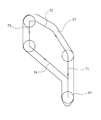
図5は、本発明の実施の形態に係るミシンの糸通し装置の概要を示す斜視図である。図5は、糸通しを行う前の状態を示しており、糸通し棒4の構造をわかりやすくするために、糸通し棒4と針棒15との距離を実際より離して記載している。
FIG. 5 is a perspective view showing an outline of a threading device for a sewing machine according to an embodiment of the present invention. FIG. 5 shows a state before threading. In order to make the structure of the threading
操作者が片手で操作体17を下降させた場合、糸通し棒4は針棒15と一体となって下降する。針棒15は、第1のカム軸41の動作を制御するカム制御部材20が針棒抱き13に接触するまで下降する。カム制御部材20が針棒抱き13に接触し、針棒抱き13が押し下げられることにより針棒クランクロッド12が最下点となるまで、第1の糸通し案内部2及び第2の糸通し案内部3は糸通し軸4と一体となって下降する。したがって、糸通しフック5及び糸誘導部材6は回転しない。
When the operator lowers the operating body 17 with one hand, the threading
カム制御部材20が針棒抱き13に接触し、針棒クランクロッド12が最下点となった場合、針棒15及び糸通し棒4はこれ以上下降せず、第1のカム軸41がカム制御部材20の端部に接触していることから、第1のカム軸41が第1のカム穴21の上縁部分に沿って移動する。本実施の形態では、第1のカム穴21の形状により、第1のカム軸41は以下のように挙動する。
When the
図6は、第1のカム穴21の中を移動する第1のカム軸41の挙動を説明する模式図である。図6に示すように、第1のカム穴21の最上部近傍では、上下方向の幅が第1のカム軸41の軸径よりも大きくなるようにしてある。したがって、操作体17を最下点から上昇させる場合、第1のカム軸41が上昇を開始するタイミングを遅らせることができ、糸誘導部材6の糸引っかかり部62のみ先に上昇させてから糸通しフック5を針穴14aから抜き出すよう挙動を制御することができる。したがって、糸通しフック5の鉤部52に確実に上糸を引っかけてから針穴14aから引き出すことができ、確実に糸通しすることが可能となる。
FIG. 6 is a schematic diagram for explaining the behavior of the
具体的な挙動は以下の通りである。カム制御部材20が針棒抱き13に接触し、針棒クランクロッド12が最下点となっている場合、第1のカム軸41は、カム制御部材20の一端部に接触した状態で第1のカム穴21の最下端に位置している。操作体17をさらに下降させた場合、第1のカム軸41は移動ルート71に沿って移動し、糸通し軸4は回転することなく第1の糸通し案内部2及び第2の糸通し案内部3のみがさらに下降する。この時点で第2のカム軸63は第2のカム穴31に沿って移動を開始し、糸誘導部材6は上から見て反時計回りに回転することにより、針棒15の方向へ移動し始める。すなわち、第1のカム穴21と第2のカム穴31とは傾斜方向が相反していることから、1本の糸通し軸4により糸通しフック5と糸誘導部材6とを互いに逆方向に回転させることができる。
The specific behavior is as follows. When the
操作体17をさらに下降させた場合、第1のカム軸41は移動ルート72に沿って移動し、糸通し軸4は上から見て時計回りに回転し、下端に備えている糸通しフック5は針穴14aへ移動して挿通される。糸通し軸4が回転することにより、第2の糸通し案内部3の第2のカム穴31に沿って第2のカム軸63がさらに移動する。第2のカム軸63が第2のカム穴31に沿ってさらに移動することにより、糸誘導部材6は上から見て反時計回りにさらに回転し、針棒15を挟むような位置まで移動する。
When the operating body 17 is further lowered, the
このように糸通しフック5と糸誘導部材6とを互いに反対方向に回転させることにより、糸誘導部材6に引っかけられている上糸を確実に糸通しフック5まで誘導することができ、上糸の引っかけられた糸通しフック5を針穴14aから引き出すことにより、糸通しを確実に行うことができる。
In this way, by rotating the
なお、本実施の形態では、上糸をより確実に糸通しフック5へ引っかけるために、付勢部材として圧縮バネ7を用いて糸誘導部材6をさらに上下動させている。つまり、第1のカム穴21の最上点に第1のカム軸41が到達する前に、第2のカム軸63が第2のカム穴31の最下点に到達するよう第1のカム穴21及び第2のカム穴31の長さを設定し、操作体17をさらに下降させた場合、第1のカム軸41が移動ルート73に沿って移動するようにしてある。
In the present embodiment, the
このようにすることで、第2のカム軸63が第2のカム穴31の最下点に到達した後は、圧縮バネ7を圧縮して糸誘導部材6だけがさらに下降し、操作体17が最下点に到達する。したがって、糸通しフック5が針穴14aへ挿通される前に、糸誘導部材6は回転移動を終了し、糸通しフック5の鉤部52が針穴14aへ挿通された状態の位置よりも下方へ押し下げておくことができる。
In this way, after the
操作体17を上昇させ始めた場合、圧縮バネ7の弾性力により糸誘導部材6だけが上昇し、糸誘導部材6に引っかかっている上糸は、針穴14aに挿通されている糸通しフック5の鉤部52に確実に引っかかる。その状態でさらに操作体17を上昇させた場合、第1のカム軸41は、移動ルート74に沿って移動し、糸通し軸4は上から見て反時計回りに回転し、下端に備えている糸通しフック5は針穴14aから抜け出る。このとき、鉤部52に引っかかっている糸が、針穴14aを通過し、糸通しが完了する。
When the operating body 17 starts to be raised, only the
図7乃至図9は、本発明の実施の形態に係るミシンの糸通し装置の挙動を説明する正面図、模式図及び平面図である。図7(a)は、初期状態の正面図及びカムの状態を示す模式図を、図7(b)は、初期状態の糸通しフック5と糸誘導部材6との位置関係を示す平面図を、図7(c)は、カム制御部材20が下降して針棒クランクロッド12が最下点となった状態の正面図及びカムの状態を示す模式図を、図7(d)は、カム制御部材20が下降して針棒クランクロッド12が最下点となった状態の糸通しフック5と糸誘導部材6との位置関係を示す平面図を、図7(e)は、第1のカム軸41が移動ルート71に沿って上昇した状態の正面図及びカムの状態を示す模式図を、図7(f)は、第1のカム軸41が移動ルート71に沿って上昇した状態の糸通しフック5と糸誘導部材6との位置関係を示す平面図を、それぞれ示している。
7 to 9 are a front view, a schematic view, and a plan view for explaining the behavior of the threading device for the sewing machine according to the embodiment of the present invention. FIG. 7A is a front view in the initial state and a schematic diagram showing the state of the cam, and FIG. 7B is a plan view showing the positional relationship between the threading
図7(a)に示す位置から、操作者が片手で操作体17を下降させた場合、糸通し棒4は針棒15と一体となって下降し、糸通し棒4は、図7(c)に示すように、第1のカム軸41の動作を制御するカム制御部材20が針棒抱き13に接触し、針棒クランクロッド12が最下点となるまで下降する。カム制御部材20が針棒抱き13に接触し、針棒クランクロッド12が最下点に到達するまでは、糸通しフック5及び糸誘導部材6は回転しないことから、図7(b)及び(d)に示すように、糸通しフック5と糸誘導部材6との位置関係は変動しない。
When the operator lowers the operating body 17 with one hand from the position shown in FIG. 7A, the threading
図7(c)に示す位置から操作体17をさらに下降させ、図7(e)に示す位置、すなわち第1のカム軸41が第1のカム穴21の上縁部分に到達した場合、糸通し軸4は回転することなく第1の糸通し案内部2及び第2の糸通し案内部3のみがさらに下降する。したがって、糸通しフック5は回転することなく図7(b)及び(d)に示す位置から移動しない。一方、第2のカム軸63は第2のカム穴31に沿って移動を開始し、図7(f)に示すように、糸誘導部材6は上から見て反時計回りに回転することにより、針棒15の方向へ移動し始める。
When the operating body 17 is further lowered from the position shown in FIG. 7C and the position shown in FIG. 7E, that is, when the
図8(a)は、糸通しフック5が針穴14aに挿通直前の状態の正面図及びカムの状態を示す模式図を、図8(b)は、糸通しフック5が針穴14aに挿通直前の状態の糸通しフック5と糸誘導部材6との位置関係を示す平面図を、図8(c)は、操作体17が最下点にある状態での正面図及びカムの状態を示す模式図を、図8(d)は、操作体17が最下点にある状態での糸通しフック5と糸誘導部材6との位置関係を示す平面図を、図8(e)は、糸通し終了時の正面図及びカムの状態を示す模式図を、図8(f)は、糸通し終了時の糸通しフック5と糸誘導部材6との位置関係を示す平面図を、それぞれ示している。
8A is a front view of the state immediately before the
図8(a)に示すように操作体17をさらに下降させた場合、第1のカム軸41が第1のカム穴21の上縁部分に沿って移動し、糸通し軸4は上から見て時計回りに回転する。第1の糸通し案内部2及び第2の糸通し案内部3もさらに下降する。したがって、図8(b)に示すように、糸通しフック5は針穴14aに向かって回転する。一方、第2のカム軸63は第2のカム穴31に沿って移動を続け、図8(c)に示すように操作体17が最下点にある状態では、糸通しフック5の鉤部52が針穴14aに挿通された状態で、糸誘導部材6の糸引っかかり部62が鉤部52の直下へと押し下げられている。
When the operating body 17 is further lowered as shown in FIG. 8A, the
すなわち、第1のカム穴21の最上点に第1のカム軸41が到達する前に、第2のカム軸63が第2のカム穴31の最下点に到達するよう第1のカム穴21及び第2のカム穴31の長さを設定し、操作体17を下降させた場合、第1のカム軸41が移動ルート73に沿って移動するようにしてある。このようにすることで、第2のカム軸63が第2のカム穴31の最下点に到達した後は、圧縮バネ7を圧縮して糸誘導部材6だけがさらに下降し、操作体17が最下点に到達する。このようにカム穴の長さ、傾斜等を調整することにより、糸通しフック5の鉤部52と、糸誘導部材6の糸引っかかり部62との動作タイミングを調整することができ、糸通しをより確実に行うことができるようにしてある。
That is, before the
したがって、糸通しフック5が針穴14aへ挿通される前に、糸誘導部材6は回転移動を終了し、操作体17が最下点にある状態では、糸通しフック5の鉤部52が針穴14aへ挿通された状態の位置よりも糸誘導部材6が下方へ押し下げられた状態となる。この状態では、圧縮バネ7は押し下げられているので、操作者が操作体17を離した状態では、圧縮バネ7の弾性力により糸誘導部材6は押し上げられる。よって、図8(e)及び(f)に示すように、糸通しフック5と糸誘導部材6との水平方向の位置関係が変動することなく、糸誘導部材6のみが上昇する。これにより、糸引っかかり部62に引っかけられている上糸が糸通しフック5の鉤部52まで上昇し、鉤部52に確実に係止される。
Therefore, before the
図9(a)は、糸通しフック5が針穴14aから抜け出た状態の正面図及びカムの状態を示す模式図を、図9(b)は、糸通しフック5が針穴14aから抜け出た状態の糸通しフック5と糸誘導部材6との位置関係を示す平面図を、図9(c)は、カム制御部材20が針棒抱き13に接した状態の正面図及びカムの状態を示す模式図を、図9(d)は、カム制御部材20が針棒抱き13に接した状態の糸通しフック5と糸誘導部材6との位置関係を示す平面図を、図9(e)は、初期状態の正面図及びカムの状態を示す模式図を、図9(f)は、初期状態の糸通しフック5と糸誘導部材6との位置関係を示す平面図を、それぞれ示している。
9A is a front view of the state in which the
図9(a)に示すように操作体17を上昇させるにつれて、図9(b)に示すように、上糸が鉤部52に引っかけられている糸通しフック5が針穴14aから抜け出る。これに伴って、上糸が針穴14aを通過することにより、糸通しを行う。
As shown in FIG. 9 (a), as the operating body 17 is raised, as shown in FIG. 9 (b), the
さらに操作体17を上昇させた場合、第1のカム軸41は移動ルート74に沿って、すなわち第1のカム穴21の下縁部に沿って移動し、図9(c)に示すように、カム制御部材20が針棒抱き13に接した状態まで戻る。第1のカム軸41が第1のカム穴21の上縁部に沿って移動するのに伴い、糸通し軸4は上から見て反時計回りに回転する。一方、第2のカム軸63は第2のカム穴31に沿って移動を続け、図9(d)に示すように糸誘導部材6は上から見て時計回りに回転する。
When the operating body 17 is further raised, the
さらに操作体17を上昇させた場合、第1のカム軸41は第1のカム穴21の最下端に戻り、針棒15及び糸通し軸4も上昇する。第2のカム軸63は第2のカム穴31に沿って移動を続け、図9(f)に示すように糸誘導部材6は上から見て時計回りに回転して元の位置へ戻る。
When the operating body 17 is further raised, the
以上のように本実施の形態によれば、2つのカム穴の傾斜方向が反対方向であることから、1本の糸通し軸4で糸通しフック5と糸誘導部材6とを反対方向に回転させることができ、ヘッド部全体をコンパクト化することができるとともに、部品点数の減少により低コスト化を図ることが可能となる。また、細かい動きが要求される縫製時であっても、移動部分の慣性が小さいことから、縫製精度を維持するために縫製速度を減じる必要が無い。
As described above, according to the present embodiment, since the inclination directions of the two cam holes are opposite directions, the
その他、本願発明の趣旨を逸脱しない範囲において前記実施形態に種々の変更を付加した形態で実施可能である。 In addition, various modifications can be added to the above-described embodiment without departing from the spirit of the present invention.
2 第1の糸通し案内部
3 第2の糸通し案内部
4 糸通し軸
5 糸通しフック
6 糸誘導部材
13 針棒抱き
14 縫針
14a 針穴
15 針棒
17 操作体
20 カム制御部材
21 第1のカム穴
31 第2のカム穴
41 第1のカム軸
51 第1のガイド部
52 鉤部
61 第2のガイド部
62 糸引っかかり部
63 第2のカム軸
2 1st threading
Claims (2)
前記糸通し軸の下端部に固着され、縫針の針穴に挿通することが可能な鉤部と、該鉤部を針穴に誘導する第1のガイド部とを有する糸通しフックと、
前記糸通し軸の下降限界位置を、前記鉤部と縫針の針穴との高さが一致する位置に規制する位置決め部材と、
前記糸通し軸の下降限界点近傍で前記鉤部が縫針の針穴に挿通するよう前記第1のガイド部を所定角度回動させる第1の回動機構と、
前記糸通し軸の下降限界点近傍で前記鉤部まで上糸を誘導する糸誘導部材と
を備えるミシンの糸通し装置において、
前記糸誘導部材は、糸を引っ掛ける糸引っかかり部と、該糸引っかかり部を縫針方向へ誘導する第2のガイド部とを有し、
前記糸通し軸の下降限界点近傍で前記糸引っかかり部が縫針の位置を越えて縫針と交差するよう前記第2のガイド部を所定角度回動させる第2の回動機構を備え、
前記第1の回動機構及び前記第2の回動機構は、前記糸通しフック及び前記糸誘導部材を互いに反対方向に回転させ、
前記糸通し軸に外嵌又は内嵌されてミシン本体に固着されており、周面に第1のカム穴及び第2のカム穴を有する糸通し案内部材を有し、
前記第1の回動機構は、前記第1のカム穴、及び前記糸通し軸に設けてある、前記第1のカム穴に嵌合する第1のカム軸を備え、
前記第2の回動機構は、前記第2のカム穴、及び前記糸誘導部材に設けてある、前記第2のカム穴に嵌合する第2のカム軸を備え、
前記第1のカム穴の傾斜方向と、前記第2のカム穴の傾斜方向とが反対方向となるようにしてあり、
前記第1のカム穴の最上部近傍での上下方向の幅は、前記第1のカム軸の軸径よりも大きくなるようにしてあり、
前記糸通しフックと前記糸誘導部材との間に、前記糸通しフックと前記糸誘導部材とを離隔させるよう付勢する付勢部材を備えることを特徴とするミシンの糸通し装置。 A threading shaft which is close to a needle bar for moving the supported sewing needle up and down, can be moved up and down, and is supported so as to be able to rotate around the shaft;
A threading hook having a collar portion fixed to the lower end portion of the threading shaft and capable of being inserted into a needle hole of a sewing needle, and a first guide portion for guiding the collar portion to the needle hole;
A positioning member that regulates the lowering limit position of the threading shaft to a position where the height of the collar portion and the needle hole of the sewing needle coincide with each other;
A first rotation mechanism for rotating the first guide portion by a predetermined angle so that the collar portion is inserted into a needle hole of a sewing needle in the vicinity of a lowering limit point of the threading shaft;
A threading device for a sewing machine comprising: a thread guiding member that guides an upper thread to the collar near the lowering limit point of the threading shaft;
The thread guiding member has a thread catching part for hooking a thread, and a second guide part for guiding the thread catching part in the sewing needle direction,
A second turning mechanism for turning the second guide portion by a predetermined angle so that the thread catching portion crosses the sewing needle beyond the position of the sewing needle in the vicinity of the lowering limit point of the threading shaft;
The first rotating mechanism and the second rotating mechanism rotate the threading hook and the thread guiding member in opposite directions ,
A threading guide member that is externally or internally fitted to the threading shaft and is fixed to the sewing machine body, and has a first cam hole and a second cam hole on the peripheral surface;
The first rotation mechanism includes a first cam shaft that is provided in the first cam hole and the threading shaft, and is fitted in the first cam hole.
The second rotating mechanism includes a second cam shaft that is provided in the second cam hole and the yarn guiding member, and is fitted in the second cam hole.
The inclination direction of the first cam hole and the inclination direction of the second cam hole are opposite to each other,
The vertical width in the vicinity of the top of the first cam hole is larger than the shaft diameter of the first cam shaft,
A threading device for a sewing machine, comprising: a biasing member that biases the threading hook and the thread guiding member to be separated from each other between the threading hook and the thread guiding member .
Priority Applications (7)
| Application Number | Priority Date | Filing Date | Title |
|---|---|---|---|
| JP2007014450A JP4139843B2 (en) | 2007-01-25 | 2007-01-25 | Sewing machine threading device |
| PCT/JP2007/071990 WO2008090663A1 (en) | 2007-01-25 | 2007-11-13 | Threader of sewing machine |
| CN2007800503899A CN101646819B (en) | 2007-01-25 | 2007-11-13 | Threader of sewing machine |
| EP07831720.3A EP2116646B1 (en) | 2007-01-25 | 2007-11-13 | Threader of sewing machine |
| US12/524,155 US8100068B2 (en) | 2007-01-25 | 2007-11-13 | Threader of sewing machine |
| TW096143850A TWI394878B (en) | 2007-01-25 | 2007-11-20 | Sewing machine threading device |
| HK10107619.4A HK1141317A1 (en) | 2007-01-25 | 2010-08-10 | Threader of sewing machine |
Applications Claiming Priority (1)
| Application Number | Priority Date | Filing Date | Title |
|---|---|---|---|
| JP2007014450A JP4139843B2 (en) | 2007-01-25 | 2007-01-25 | Sewing machine threading device |
Publications (2)
| Publication Number | Publication Date |
|---|---|
| JP2008178565A JP2008178565A (en) | 2008-08-07 |
| JP4139843B2 true JP4139843B2 (en) | 2008-08-27 |
Family
ID=39644241
Family Applications (1)
| Application Number | Title | Priority Date | Filing Date |
|---|---|---|---|
| JP2007014450A Active JP4139843B2 (en) | 2007-01-25 | 2007-01-25 | Sewing machine threading device |
Country Status (7)
| Country | Link |
|---|---|
| US (1) | US8100068B2 (en) |
| EP (1) | EP2116646B1 (en) |
| JP (1) | JP4139843B2 (en) |
| CN (1) | CN101646819B (en) |
| HK (1) | HK1141317A1 (en) |
| TW (1) | TWI394878B (en) |
| WO (1) | WO2008090663A1 (en) |
Cited By (1)
| Publication number | Priority date | Publication date | Assignee | Title |
|---|---|---|---|---|
| US9410275B2 (en) | 2013-07-10 | 2016-08-09 | Janome Sewing Machine Co., Ltd. | Thread holding mechanism of sewing machine, needle threader thereof, and sewing machine |
Families Citing this family (7)
| Publication number | Priority date | Publication date | Assignee | Title |
|---|---|---|---|---|
| DE112011103955B4 (en) * | 2010-11-29 | 2018-03-15 | Jaguar International Corporation | Threading device for sewing machine lower looper |
| US9212439B2 (en) * | 2012-02-22 | 2015-12-15 | Jaguar International Corporation | Threader for overlock machine |
| CN103774356B (en) * | 2013-12-20 | 2016-04-13 | 宁波瑞铭机械有限公司 | Use in sewing machine automatic threading apparatus |
| JP6386241B2 (en) * | 2014-03-11 | 2018-09-05 | 蛇の目ミシン工業株式会社 | Sewing machine with threading device |
| JP6680462B2 (en) * | 2015-03-30 | 2020-04-15 | 蛇の目ミシン工業株式会社 | Sewing machine threading device |
| CN106087297B (en) * | 2016-08-30 | 2019-05-07 | 杰克缝纫机股份有限公司 | A kind of automatic threader of sewing machine |
| JP6718188B1 (en) * | 2019-11-28 | 2020-07-08 | 株式会社鈴木製作所 | Sewing machine threading device |
Family Cites Families (20)
| Publication number | Priority date | Publication date | Assignee | Title |
|---|---|---|---|---|
| US2707448A (en) * | 1951-06-12 | 1955-05-03 | Naas Nils Reinhold | Needle threader device |
| JP2917438B2 (en) | 1990-07-04 | 1999-07-12 | ブラザー工業株式会社 | Sewing machine threading device |
| JP3335491B2 (en) * | 1994-12-26 | 2002-10-15 | ブラザー工業株式会社 | Sewing machine threading device |
| JP3730300B2 (en) | 1996-01-18 | 2005-12-21 | Juki株式会社 | Sewing machine threading device |
| JP3796963B2 (en) | 1998-05-25 | 2006-07-12 | ブラザー工業株式会社 | Sewing machine threading device |
| JP3094990B2 (en) * | 1998-06-22 | 2000-10-03 | ブラザー工業株式会社 | Threading sewing machine |
| DE19961923A1 (en) * | 1999-12-22 | 2001-07-05 | Bosch Gmbh Robert | Fuel delivery module for vehicle has jet pump that pumps fuel from fuel tank to storage container next to feed assembly, connected to flow channel by channel on storage container floor |
| JP2001218992A (en) * | 2000-02-09 | 2001-08-14 | Juki Corp | Threading device for sewing machine |
| JP2002200386A (en) | 2000-12-27 | 2002-07-16 | Brother Ind Ltd | Thread inserting device for sewing machine |
| JP4465877B2 (en) | 2000-12-27 | 2010-05-26 | ブラザー工業株式会社 | Sewing machine threading device |
| EP1256648B1 (en) * | 2001-04-30 | 2007-03-07 | Fritz Gegauf AG | Device for inserting a needle thread through the eye of a sewing machine needle |
| JP4789360B2 (en) * | 2001-07-12 | 2011-10-12 | 蛇の目ミシン工業株式会社 | Sewing machine with needle threading device |
| JP2004024539A (en) * | 2002-06-25 | 2004-01-29 | Aisin Seiki Co Ltd | Sewing machine |
| JPWO2004048668A1 (en) * | 2002-11-26 | 2006-03-23 | 宮本株式会社 | Embroidery robot |
| JP4272008B2 (en) * | 2003-07-31 | 2009-06-03 | 蛇の目ミシン工業株式会社 | Sewing machine threading device and sewing machine equipped with threading device |
| JP4272042B2 (en) | 2003-11-28 | 2009-06-03 | 蛇の目ミシン工業株式会社 | Sewing machine threading device. |
| US6918344B2 (en) * | 2003-11-28 | 2005-07-19 | Janome Sewing Machine Co., Ltd. | Threading device of sewing machine |
| JP2005342158A (en) * | 2004-06-02 | 2005-12-15 | Brother Ind Ltd | Sewing machine |
| JP2006061398A (en) * | 2004-08-26 | 2006-03-09 | Akkusu Yamazaki:Kk | Needle threader |
| JP4466348B2 (en) * | 2004-12-02 | 2010-05-26 | ブラザー工業株式会社 | Sewing machine threading device and sewing machine |
-
2007
- 2007-01-25 JP JP2007014450A patent/JP4139843B2/en active Active
- 2007-11-13 US US12/524,155 patent/US8100068B2/en active Active
- 2007-11-13 EP EP07831720.3A patent/EP2116646B1/en active Active
- 2007-11-13 CN CN2007800503899A patent/CN101646819B/en active Active
- 2007-11-13 WO PCT/JP2007/071990 patent/WO2008090663A1/en active Application Filing
- 2007-11-20 TW TW096143850A patent/TWI394878B/en active
-
2010
- 2010-08-10 HK HK10107619.4A patent/HK1141317A1/en unknown
Cited By (1)
| Publication number | Priority date | Publication date | Assignee | Title |
|---|---|---|---|---|
| US9410275B2 (en) | 2013-07-10 | 2016-08-09 | Janome Sewing Machine Co., Ltd. | Thread holding mechanism of sewing machine, needle threader thereof, and sewing machine |
Also Published As
| Publication number | Publication date |
|---|---|
| WO2008090663A1 (en) | 2008-07-31 |
| CN101646819A (en) | 2010-02-10 |
| EP2116646B1 (en) | 2014-04-02 |
| EP2116646A4 (en) | 2012-12-19 |
| US8100068B2 (en) | 2012-01-24 |
| EP2116646A1 (en) | 2009-11-11 |
| JP2008178565A (en) | 2008-08-07 |
| US20100043686A1 (en) | 2010-02-25 |
| TW200837243A (en) | 2008-09-16 |
| TWI394878B (en) | 2013-05-01 |
| CN101646819B (en) | 2011-11-30 |
| HK1141317A1 (en) | 2010-11-05 |
Similar Documents
| Publication | Publication Date | Title |
|---|---|---|
| JP4139843B2 (en) | Sewing machine threading device | |
| JP2009219780A (en) | Two-needle sewing machine | |
| JP2002113281A (en) | Sewing machine having thread passing device | |
| JP2003038879A (en) | Needle thread control device of multi-needle multi- thread chain stitch sewing machine | |
| US6973888B2 (en) | Sewing machine and a needle threading device thereof | |
| AU2012364665B2 (en) | Threader for overlock machine | |
| JP7185438B2 (en) | Sewing machine with threading device | |
| JP4799765B2 (en) | Sewing thread threading device | |
| JP2009095503A (en) | Presser foot for sewing machine and sewing machine | |
| JP4029643B2 (en) | sewing machine | |
| JP4195903B2 (en) | Sewing machine threading device | |
| US6918344B2 (en) | Threading device of sewing machine | |
| JP3455565B2 (en) | Sewing machine cartridge | |
| JP2010088760A (en) | Needle threader for sewing machine | |
| CN102011277A (en) | Sewing machine | |
| KR100944296B1 (en) | Sewing machine | |
| JP5132020B2 (en) | Sewing machine with threading device | |
| JP7438016B2 (en) | sewing machine | |
| JP3730300B2 (en) | Sewing machine threading device | |
| US4248169A (en) | Intermittently operable needle thread snubber | |
| JPH0464386A (en) | Threading device for sewing machine | |
| JP2904539B2 (en) | Sewing machine balance mechanism | |
| JP2002191884A (en) | Sewing machine | |
| JP3608281B2 (en) | sewing machine | |
| JP5115689B2 (en) | Sewing machine threading device |
Legal Events
| Date | Code | Title | Description |
|---|---|---|---|
| A521 | Request for written amendment filed |
Free format text: JAPANESE INTERMEDIATE CODE: A523 Effective date: 20080520 |
|
| A621 | Written request for application examination |
Free format text: JAPANESE INTERMEDIATE CODE: A621 Effective date: 20080520 |
|
| A871 | Explanation of circumstances concerning accelerated examination |
Free format text: JAPANESE INTERMEDIATE CODE: A871 Effective date: 20080520 |
|
| TRDD | Decision of grant or rejection written | ||
| A975 | Report on accelerated examination |
Free format text: JAPANESE INTERMEDIATE CODE: A971005 Effective date: 20080529 |
|
| A01 | Written decision to grant a patent or to grant a registration (utility model) |
Free format text: JAPANESE INTERMEDIATE CODE: A01 Effective date: 20080603 |
|
| A01 | Written decision to grant a patent or to grant a registration (utility model) |
Free format text: JAPANESE INTERMEDIATE CODE: A01 |
|
| A61 | First payment of annual fees (during grant procedure) |
Free format text: JAPANESE INTERMEDIATE CODE: A61 Effective date: 20080609 |
|
| R150 | Certificate of patent or registration of utility model |
Ref document number: 4139843 Country of ref document: JP Free format text: JAPANESE INTERMEDIATE CODE: R150 Free format text: JAPANESE INTERMEDIATE CODE: R150 |
|
| FPAY | Renewal fee payment (event date is renewal date of database) |
Free format text: PAYMENT UNTIL: 20110613 Year of fee payment: 3 |
|
| R250 | Receipt of annual fees |
Free format text: JAPANESE INTERMEDIATE CODE: R250 |
|
| R250 | Receipt of annual fees |
Free format text: JAPANESE INTERMEDIATE CODE: R250 |
|
| R250 | Receipt of annual fees |
Free format text: JAPANESE INTERMEDIATE CODE: R250 |
|
| R250 | Receipt of annual fees |
Free format text: JAPANESE INTERMEDIATE CODE: R250 |
|
| R250 | Receipt of annual fees |
Free format text: JAPANESE INTERMEDIATE CODE: R250 |
|
| R250 | Receipt of annual fees |
Free format text: JAPANESE INTERMEDIATE CODE: R250 |
|
| R250 | Receipt of annual fees |
Free format text: JAPANESE INTERMEDIATE CODE: R250 |
|
| S111 | Request for change of ownership or part of ownership |
Free format text: JAPANESE INTERMEDIATE CODE: R313113 |
|
| R350 | Written notification of registration of transfer |
Free format text: JAPANESE INTERMEDIATE CODE: R350 |
|
| R250 | Receipt of annual fees |
Free format text: JAPANESE INTERMEDIATE CODE: R250 |
|
| RD02 | Notification of acceptance of power of attorney |
Free format text: JAPANESE INTERMEDIATE CODE: R3D02 |
|
| R250 | Receipt of annual fees |
Free format text: JAPANESE INTERMEDIATE CODE: R250 |