JP4138427B2 - Illumination mechanism - Google Patents
Illumination mechanism Download PDFInfo
- Publication number
- JP4138427B2 JP4138427B2 JP2002283353A JP2002283353A JP4138427B2 JP 4138427 B2 JP4138427 B2 JP 4138427B2 JP 2002283353 A JP2002283353 A JP 2002283353A JP 2002283353 A JP2002283353 A JP 2002283353A JP 4138427 B2 JP4138427 B2 JP 4138427B2
- Authority
- JP
- Japan
- Prior art keywords
- light guide
- guide member
- light
- illumination
- transparent
- Prior art date
- Legal status (The legal status is an assumption and is not a legal conclusion. Google has not performed a legal analysis and makes no representation as to the accuracy of the status listed.)
- Expired - Fee Related
Links
Images
Classifications
-
- G—PHYSICS
- G02—OPTICS
- G02B—OPTICAL ELEMENTS, SYSTEMS OR APPARATUS
- G02B6/00—Light guides; Structural details of arrangements comprising light guides and other optical elements, e.g. couplings
- G02B6/0001—Light guides; Structural details of arrangements comprising light guides and other optical elements, e.g. couplings specially adapted for lighting devices or systems
- G02B6/0005—Light guides; Structural details of arrangements comprising light guides and other optical elements, e.g. couplings specially adapted for lighting devices or systems the light guides being of the fibre type
- G02B6/0006—Coupling light into the fibre
Description
【0001】
【発明の属する技術分野】
本発明は、操作パネルなどに組み込まれた導光体によって光源の光を照光領域へと導く照光機構に係り、特に、照光色の異なる複数の照光領域を有する装置に用いて好適な照光機構に関する。
【0002】
【従来の技術】
車載用の操作パネルには、夜間などの暗所における視認性を確保するために、内蔵した光源の光によって操作部やその周辺を照光可能とする照光機構が備えられている。かかる照光機構には、通常、ランプやLED等の光源だけでなく、光源の光を所定の照光領域へと導く導光体が使用されている。
【0003】
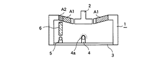
図3は、従来の照光機構の一例を示す断面図である。同図において、パネル部材1は操作つまみ2の周辺が照光領域A1,A2となっている。これらの照光領域A1,A2は無色透明な領域に有色印刷を施して形成したものであり、操作つまみ2を包囲する比較的広い照光領域A1は第1の照光色(例えば黄橙色)に着色されており、それよりも狭い照光領域A2は第2の照光色(例えば青色)に着色されている。パネル部材1の内部に組み込まれた回路基板3上には、操作つまみ2の後方に位置する光源4と、照光領域A2の後方に位置する光源5とが並設されており、光源5と照光領域A2との間には無色透明な柱状の導光体6が介設されている。この導光体6はアクリル樹脂等の光透過性材料からなり、光源5から出射された白色光を効率よく照光領域A2へと導くので、照光領域A2を印刷色を反映した第2の照光色で照光させることができる。また、光源4には調色キャップ4aが取り付けてあるので、光源4から出射された白色光は調色キャップ4aを透過すると第1の照光色に近い色に変化して照光領域A1に照射される。したがって、照光領域A1を主たる照光色である第1の照光色で照光させることができる。
【0004】
なお、照光領域A1,A2の照光色がほぼ同系色であれば、後方から同じ色の光を照射しても印刷色によって区別することが可能であるが、実際には、両照光領域A1,A2を明確に区別できるような照光色(例えば一方で暖色系で他方が寒色系)に設定されることが多いので、図3に示すように各照光領域A1,A2に対して後方から異なる色の光を照射するという構成が広く採用されている。
【0005】
【発明が解決しようとする課題】
上述したように複数の照光領域A1,A2に対して後方から同じ色の光を照射することができない場合、従来は図3に示すように各照光領域A1,A2ごとに光源4,5を配設して調色キャップ4aや導光体6を併用しているが、かかる構成は部品点数が多くなってしまうので、照光機構の高コスト化を余儀なくされるという問題があった。
【0006】
本発明は、このような従来技術の実情に鑑みてなされたもので、その目的は、共通の光源を用いて複数の照光領域に対して異なる色の照射光を供給することができ、もって低コスト化が図れる照光機構を提供することにある。
【0007】
【課題を解決するための手段】
上述した目的を達成するため、本発明の照光機構では、光透過性材料からなり光源を覆う位置に配置された第1の導光部材と、光透過性材料からなり前記第1の導光部材に密着接合されて一端面を前記光源に対向させ、かつ他端面を所定の照光領域に対向させた第2の導光部材とを備え、これら第1および第2の導光部材のいずれか一方が無色透明で他方が有色透明である照光機構であって、前記第1の導光部材の光透過性材料が前記第2の導光部材の光透過性材料よりも溶融温度が高く、かつ、予め成形した前記第1の導光部材を前記第2の導光部材の成形金型の一部として使用する2色成形を行うことによってこれら両導光部材が一体化されている構成とした。
【0008】
このように有色透明な導光部材と無色透明な導光部材とを密着接合してなる導光体を用いると、光源から出射された光のうち、有色透明な導光部材を透過して色が変化した光が照射される照光領域と、無色透明な導光部材を透過した光が照射される別の照光領域とで、照光色を大きく異ならせることができるため、照光機構の光源の数が減らせ調色キャップも不要となる。
【0009】
また、かかる導光体は2色成形技術によって製造することが好ましい。すなわち、第1の導光部材の光透過性材料として第2の導光部材の光透過性材料よりも溶融温度の高いもの(例えば前者がポリカーボネイト樹脂で後者がアクリル樹脂)を選択し、予め成形した第1の導光部材を第2の導光部材の成形金型の一部として使用する2色成形を行うことによって、これら両導光部材を一体化してなる導光体を容易に製造できる。
【0010】
また、かかる導光体は、第1の導光部材が有色透明で第2の導光部材が無色透明であることが好ましい。すなわち、無色透明な導光部材は光透過率が高いので、第2の導光部材の一端面に入射される光源の光は光路長が長くても他端面まで効率よく導かれることとなり、一方、有色透明な導光部材は内壁面に入射される光源の光を短い光路長で外壁面から出射させれば調色機能を果たすので、第1の導光部材によって照射される照光領域が輝度不足を起こす心配もなくなる。
【0011】
その場合、無色透明な第2の導光部材が、有色透明な第1の導光部材の外表面を被覆する被覆部と、この被覆部から突出する光案内部とを有すると共に、該被覆部と第1の導光部材とからなる積層構造部に光源が配置される内側の空間を外側の空間と連通させるための切欠きを設けておけば、第1および第2の導光部材を広い面積で密着接合させることができるため機械的強度が確保しやすくなると共に、光源の発生する熱が積層構造部の外部へ放出されやすくなるので導光体の熱損傷が防止できて好ましい。
【0012】
【発明の実施の形態】
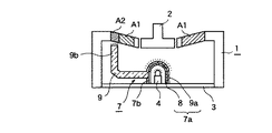
発明の実施の形態について図面を参照して説明すると、図1は本発明の実施形態例に係る照光機構の説明図、図2は該照光機構に備えられる導光体の斜視図であり、図3に対応する部分には同一符号を付してある。
【0013】
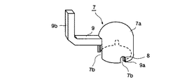
図1,2において、符号7は2色成形技術によって製造した導光体である。この導光体7は、ポリカーボネイト樹脂に顔料を添加して薄橙色に染色した光透過性の導光部材8と、アクリル樹脂からなる無色透明な導光部材9とを密着接合した構造になっている。有色透明な導光部材8は略半球状に成形されたモールド品であり、光源4を覆う位置に配置されて照光領域A1に照射光を供給する。無色透明な導光部材9は、導光部材8の外表面を被覆する略半球状の被覆部9aと、略直角に折れ曲がった棒状体である光案内部9bとからなるモールド品である。この導光部材9は、光案内部9bの一端面が光源4と対向して他端面が照光領域A2と対向するように配置され、照光領域A2に照射光を供給する。つまり、導光体7は外観上、導光部材8と被覆部9aとが密着接合されている略半球状の積層構造部7aと、この積層構造部7aから側方へ突出して前方へ延びるL字状の光案内部9bとに区別することができる。なお、積層構造部7aの複数箇所には、内側の空間を外側の空間と連通させるための切欠き7bが設けられている。
【0014】
かかる導光体7を製造する際には、まず導光部材8を成形し、次いでこの導光部材8を成形金型の一部として導光部材9を成形するという2色成形を行う。このとき、導光部材8の材料であるポリカーボネイト樹脂は耐熱性が高く、導光部材9の材料であるアクリル樹脂の溶融温度では溶融しないので、導光部材9の成形時に導光部材8が変形することはない。こうして2色成形を行うことにより、有色透明な導光部材8と無色透明な導光部材9とが密着接合された一体品の導光体7が得られる。この導光体7の第1および第2の導光部材8,9は、広い面積で密着接合しているため強固に一体化されている。
【0015】
図1に示すように、かかる導光体7が組み込まれた照光機構には操作つまみ2の周辺に照光領域A1,A2が設けられている。これらの照光領域A1,A2はパネル部材1の無色透明な領域に有色印刷を施して形成したものであり、操作つまみ2を包囲する比較的広い照光領域A1は第1の照光色(黄橙色)に着色されており、それよりも狭い照光領域A2は第2の照光色(青色)に着色されている。また、パネル部材1の内部に組み込まれた回路基板3上には、操作つまみ2の後方に光源4が実装されており、この光源4を覆う位置に導光体7の積層構造部7aが配置されている。したがって、光源4から出射された白色光は薄橙色の導光部材8を透過すると第1の照光色に近い色に変化し、この光が無色透明な被覆部9aを透過して照光領域A1に後方から照射されることになる。これにより、照光領域A1を主たる照光色である第1の照光色で照光させることができる。また、導光体7の光案内部9bは一端面が光源4と対向して他端面が照光領域A2と対向するように配置されているので、光源4の白色光を色を変化させずにそのまま照光領域A2へと導くことができる。これにより、照光領域A2を印刷色を反映した第2の照光色で照光させることができる。
【0016】
なお、有色透明な第1の導光部材8は、内壁面に入射される光源4の光を短い光路長で外壁面から出射させて調色機能を果たすので、第1の導光部材8によって照射される照光領域A1が輝度不足を起こす心配はない。また、無色透明な第2の導光部材9は光透過率が高いので、光案内部9bの一端面に入射される光源4の光は光路長が長くても他端面まで効率よく導かれ、よって照光領域A2が輝度不足を起こす心配もない。
【0017】
このように本実施形態例においては、有色透明な導光部材8と無色透明な導光部材9とを密着接合してなる導光体7を用いているため、互いの照光色が大きく異なる照光領域A1と照光領域A2を共通の光源4によって照光させることができて、調色キャップも不要となっている。また、この導光体7は2色成形技術によって容易に製造できる。したがって、光源や調色キャップ等の部品点数削減に伴い簡素な構成の照光機構が実現できて、顕著なコストダウンが期待できる。
【0018】
また、本実施形態例で用いた導光体7は、積層構造部7aの内壁側を耐熱性の高いポリカーボネイト樹脂製の導光部材8とし、かつ積層構造部7aに切欠き7bを設けて光源4の熱を外部へ放出しやすくしているので、光源4に調色キャップ4aを直接取り付けていた従来例(図3参照)に比べると、光源4の熱で導光体7が損傷する心配はない。
【0019】
なお、本実施形態例で用いた導光体7には光源4の光を所定の照光領域へと導く光案内部9bが一つだけしか設けていないが、同様の光案内部を複数箇所に突出形成したり分岐形成しておけば、導光部材9によって複数箇所の照光領域に光源4の光を分配することができる。
【0020】
【発明の効果】
本発明は、以上説明したような形態で実施され、以下に記載されるような効果を奏する。
【0021】
有色透明な導光部材と無色透明な導光部材とを密着接合してなる導光体を用いており、光源から出射された光のうち、有色透明な導光部材を透過して色が変化した光が照射される照光領域と、無色透明な導光部材を透過した光が照射される別の照光領域とで、照光色を大きく異ならせることができるため、照光機構の光源の数が減らせ調色キャップも不要となる。それゆえ、部品点数の削減に伴って簡素な構成の照光機構が実現できて、顕著なコストダウンが期待できる。また、かかる導光体は2色成形技術によって容易に製造することができる。
【図面の簡単な説明】
【図1】本発明の実施形態例に係る照光機構の断面図である。
【図2】該照光機構に備えられる導光体の斜視図である。
【図3】従来例に係る照光機構の断面図である。
【符号の説明】
1 パネル部材
2 操作つまみ
3 回路基板
4 光源
7 導光体
7a 積層構造部
7b 切欠き
8 導光部材(第1の導光部材)
9 導光部材(第2の導光部材)
9a 被覆部
9b 光案内部
A1,A2 照光領域[0001]
BACKGROUND OF THE INVENTION
The present invention relates to an illumination mechanism that guides light from a light source to an illumination area by a light guide incorporated in an operation panel or the like, and more particularly, to an illumination mechanism that is suitable for use in an apparatus having a plurality of illumination areas having different illumination colors. .
[0002]
[Prior art]
In order to ensure visibility in a dark place such as at night, an in-vehicle operation panel is provided with an illumination mechanism that can illuminate the operation unit and its surroundings with light from a built-in light source. In such an illumination mechanism, not only a light source such as a lamp or an LED but also a light guide that guides light from the light source to a predetermined illumination area is used.
[0003]
FIG. 3 is a cross-sectional view showing an example of a conventional illumination mechanism. In the figure, the
[0004]
In addition, if the illumination colors of the illumination areas A1 and A2 are substantially similar colors, it is possible to distinguish them according to the print color even if the same color light is irradiated from the rear. Since it is often set to an illumination color that can clearly distinguish A2 (for example, one is a warm color system and the other is a cold color system), as shown in FIG. 3, different colors from the rear for each illumination area A1, A2 The structure of irradiating the light is widely adopted.
[0005]
[Problems to be solved by the invention]
As described above, when it is impossible to irradiate a plurality of illumination areas A1 and A2 with the same color light from the rear, conventionally, as shown in FIG. 3,
[0006]
The present invention has been made in view of the situation of the prior art as described above, and an object of the present invention is to supply irradiation light of different colors to a plurality of illumination areas using a common light source. The object is to provide an illumination mechanism capable of reducing the cost.
[0007]
[Means for Solving the Problems]
In order to achieve the above object, in the illumination mechanism of the present invention, a first light guide member made of a light transmissive material and disposed at a position covering the light source, and the first light guide member made of a light transmissive material. And a second light guide member having one end face opposed to the light source and the other end face opposed to a predetermined illumination region, and one of the first and second light guide members Is an illuminating mechanism in which the other is colored and transparent , and the light-transmissive material of the first light guide member has a melting temperature higher than that of the light-transmissive material of the second light guide member, and The two light guide members are integrated by performing two-color molding using the preliminarily molded first light guide member as a part of a molding die of the second light guide member .
[0008]
When a light guide body formed by tightly joining a colored transparent light guide member and a colorless and transparent light guide member in this way is used, the light transmitted from the light source passes through the colored transparent light guide member and is colored. Since the illumination color can be greatly different between the illumination area irradiated with the light having changed and the other illumination area irradiated with the light transmitted through the colorless and transparent light guide member, the number of light sources of the illumination mechanism The toning cap becomes unnecessary.
[0009]
Further, such light guide is preferably manufactured by two-color molding technique. That is, a material having a higher melting temperature than the light transmissive material of the second light guide member (for example, the former is polycarbonate resin and the latter is acrylic resin) is selected and molded in advance. By performing two-color molding using the first light guide member as a part of the molding die for the second light guide member, a light guide body in which these light guide members are integrated can be easily manufactured. .
[0010]
Further, in such a light guide, it is preferable that the first light guide member is colored and transparent and the second light guide member is colorless and transparent. That is, since the colorless and transparent light guide member has high light transmittance, the light of the light source incident on one end surface of the second light guide member is efficiently guided to the other end surface even if the optical path length is long. The colored transparent light guide member performs a color matching function if the light of the light source incident on the inner wall surface is emitted from the outer wall surface with a short optical path length, so that the illumination region irradiated by the first light guide member has luminance There is no need to worry about shortages.
[0011]
In that case, the colorless and transparent second light guide member includes a covering portion that covers the outer surface of the colored and transparent first light guide member, and a light guide portion that protrudes from the covering portion, and the covering portion. If the notch for connecting the inner space where the light source is disposed to the outer space is provided in the laminated structure portion composed of the first light guide member and the first light guide member, the first and second light guide members can be widened. Since it can be tightly bonded by area, it is easy to ensure mechanical strength, and heat generated by the light source is easily released to the outside of the laminated structure portion, which is preferable because thermal damage to the light guide can be prevented.
[0012]
DETAILED DESCRIPTION OF THE INVENTION
FIG. 1 is an explanatory view of an illumination mechanism according to an embodiment of the present invention, and FIG. 2 is a perspective view of a light guide provided in the illumination mechanism. Parts corresponding to 3 are given the same reference numerals.
[0013]
1 and 2,
[0014]
When manufacturing the
[0015]
As shown in FIG. 1, the illumination mechanism incorporating the
[0016]
In addition, the colored transparent first
[0017]
Thus, in this embodiment, since the
[0018]
In addition, the
[0019]
The
[0020]
【The invention's effect】
The present invention is implemented in the form as described above, and has the following effects.
[0021]
Uses a light guide that is formed by tightly joining a colored transparent light guide member and a colorless and transparent light guide member, and changes the color of light emitted from the light source through the colored transparent light guide member. The illumination color can be greatly different between the illumination area where the irradiated light is irradiated and the other illumination area where the light transmitted through the colorless and transparent light guide member is irradiated, so the number of light sources of the illumination mechanism can be reduced. A toning cap is also unnecessary. Therefore, an illumination mechanism having a simple configuration can be realized as the number of parts is reduced, and a significant cost reduction can be expected. Such a light guide can be easily manufactured by a two-color molding technique.
[Brief description of the drawings]
FIG. 1 is a cross-sectional view of an illumination mechanism according to an embodiment of the present invention.
FIG. 2 is a perspective view of a light guide provided in the illumination mechanism.
FIG. 3 is a cross-sectional view of an illumination mechanism according to a conventional example.
[Explanation of symbols]
DESCRIPTION OF
9 Light guide member (second light guide member)
Claims (3)
前記第1の導光部材の光透過性材料が前記第2の導光部材の光透過性材料よりも溶融温度が高く、かつ、予め成形した前記第1の導光部材を前記第2の導光部材の成形金型の一部として使用する2色成形を行うことによってこれら両導光部材が一体化されていることを特徴とする照光機構。A first light guide member made of a light transmissive material and disposed at a position covering the light source; and a first light guide member made of a light transmissive material that is in close contact with the first light guide member and having one end face opposed to the light source; and and a second light guide member and the other end face is opposed to a predetermined illumination area, there in the first and second one is colorless and transparent and the other is colored transparent der Ru illuminating mechanism of the light guide member And
The light transmissive material of the first light guide member has a melting temperature higher than that of the light transmissive material of the second light guide member, and the first light guide member molded in advance is used as the second light guide member. An illumination mechanism characterized in that these light guide members are integrated by performing two-color molding used as a part of a molding die of an optical member .
Priority Applications (3)
| Application Number | Priority Date | Filing Date | Title |
|---|---|---|---|
| JP2002283353A JP4138427B2 (en) | 2002-09-27 | 2002-09-27 | Illumination mechanism |
| DE2003620195 DE60320195T2 (en) | 2002-09-27 | 2003-09-23 | lighting device |
| EP20030021496 EP1403667B1 (en) | 2002-09-27 | 2003-09-23 | Illumination mechanism |
Applications Claiming Priority (1)
| Application Number | Priority Date | Filing Date | Title |
|---|---|---|---|
| JP2002283353A JP4138427B2 (en) | 2002-09-27 | 2002-09-27 | Illumination mechanism |
Publications (2)
| Publication Number | Publication Date |
|---|---|
| JP2004118008A JP2004118008A (en) | 2004-04-15 |
| JP4138427B2 true JP4138427B2 (en) | 2008-08-27 |
Family
ID=31973349
Family Applications (1)
| Application Number | Title | Priority Date | Filing Date |
|---|---|---|---|
| JP2002283353A Expired - Fee Related JP4138427B2 (en) | 2002-09-27 | 2002-09-27 | Illumination mechanism |
Country Status (3)
| Country | Link |
|---|---|
| EP (1) | EP1403667B1 (en) |
| JP (1) | JP4138427B2 (en) |
| DE (1) | DE60320195T2 (en) |
Families Citing this family (1)
| Publication number | Priority date | Publication date | Assignee | Title |
|---|---|---|---|---|
| US9822944B2 (en) * | 2015-05-22 | 2017-11-21 | Magna International Inc. | Vehicle light assembly having a colored appearance in an unlit state |
Family Cites Families (2)
| Publication number | Priority date | Publication date | Assignee | Title |
|---|---|---|---|---|
| DE561922C (en) * | 1930-01-28 | 1932-10-19 | Sendlinger Optische Glaswerke | Luminaire with a light source arranged inside a container with reflective walls and distant light exit points |
| DE2029317A1 (en) * | 1970-06-13 | 1971-12-16 | Hanel G | Bifunction light |
-
2002
- 2002-09-27 JP JP2002283353A patent/JP4138427B2/en not_active Expired - Fee Related
-
2003
- 2003-09-23 EP EP20030021496 patent/EP1403667B1/en not_active Expired - Fee Related
- 2003-09-23 DE DE2003620195 patent/DE60320195T2/en not_active Expired - Lifetime
Also Published As
| Publication number | Publication date |
|---|---|
| EP1403667B1 (en) | 2008-04-09 |
| EP1403667A1 (en) | 2004-03-31 |
| JP2004118008A (en) | 2004-04-15 |
| DE60320195T2 (en) | 2009-07-09 |
| DE60320195D1 (en) | 2008-05-21 |
Similar Documents
| Publication | Publication Date | Title |
|---|---|---|
| US11850998B2 (en) | Vehicular exterior rearview mirror assembly with ground illumination and icon projection module | |
| US11427137B2 (en) | Emblem arrangement for a motor vehicle | |
| US8469563B2 (en) | Turn-indicator light module for a vehicle mirror assembly and vehicle mirror assembly comprising a turn-indicator light module | |
| JP2001163117A (en) | Illuminating plate for automobile | |
| US20060044825A1 (en) | Lamp for vehicle | |
| US20050094405A1 (en) | Illumination device for license plate | |
| GB2489813A (en) | An illuminating formed part, especially a decorative covering part for the interior space of a vehicle | |
| JP2018512606A (en) | Light assembly for illuminating the emblem | |
| JP2010537885A (en) | Vehicle steering wheel assembly | |
| US20070081353A1 (en) | Rear lighting assembly for motor vehicles | |
| CN112601678A (en) | Lighting device for a motor vehicle | |
| JP2007523004A (en) | Signal assembly | |
| CN113167456B (en) | Lamp for a motor vehicle | |
| JP4138427B2 (en) | Illumination mechanism | |
| US11898716B2 (en) | Lighting device for a motor vehicle | |
| JP2003281908A (en) | Lighting device | |
| JP2003222541A (en) | Light emitting device | |
| JP4366682B2 (en) | Liquid crystal display | |
| JP6984334B2 (en) | Luminescent device | |
| US20230175667A1 (en) | Mini or micro led-based light module configured to perform plural light functions seamlessly with different light guides in unitary assembly | |
| CN218316534U (en) | Run-through tail lamp assembly of automobile and automobile | |
| KR102554622B1 (en) | A rearview device for vehicle including an indicator | |
| JP7139140B2 (en) | Vehicle lighting device, vehicle lamp, window panel with vehicle lamp, in-vehicle display | |
| US20240125449A1 (en) | Lighting device for vehicles | |
| CN117397028A (en) | Optoelectronic lighting device |
Legal Events
| Date | Code | Title | Description |
|---|---|---|---|
| A621 | Written request for application examination |
Free format text: JAPANESE INTERMEDIATE CODE: A621 Effective date: 20050420 |
|
| A131 | Notification of reasons for refusal |
Free format text: JAPANESE INTERMEDIATE CODE: A131 Effective date: 20080226 |
|
| A521 | Written amendment |
Free format text: JAPANESE INTERMEDIATE CODE: A523 Effective date: 20080421 |
|
| TRDD | Decision of grant or rejection written | ||
| A01 | Written decision to grant a patent or to grant a registration (utility model) |
Free format text: JAPANESE INTERMEDIATE CODE: A01 Effective date: 20080513 |
|
| A01 | Written decision to grant a patent or to grant a registration (utility model) |
Free format text: JAPANESE INTERMEDIATE CODE: A01 |
|
| A61 | First payment of annual fees (during grant procedure) |
Free format text: JAPANESE INTERMEDIATE CODE: A61 Effective date: 20080605 |
|
| R150 | Certificate of patent or registration of utility model |
Free format text: JAPANESE INTERMEDIATE CODE: R150 Ref document number: 4138427 Country of ref document: JP Free format text: JAPANESE INTERMEDIATE CODE: R150 |
|
| FPAY | Renewal fee payment (event date is renewal date of database) |
Free format text: PAYMENT UNTIL: 20110613 Year of fee payment: 3 |
|
| FPAY | Renewal fee payment (event date is renewal date of database) |
Free format text: PAYMENT UNTIL: 20120613 Year of fee payment: 4 |
|
| FPAY | Renewal fee payment (event date is renewal date of database) |
Free format text: PAYMENT UNTIL: 20120613 Year of fee payment: 4 |
|
| FPAY | Renewal fee payment (event date is renewal date of database) |
Free format text: PAYMENT UNTIL: 20130613 Year of fee payment: 5 |
|
| FPAY | Renewal fee payment (event date is renewal date of database) |
Free format text: PAYMENT UNTIL: 20140613 Year of fee payment: 6 |
|
| S533 | Written request for registration of change of name |
Free format text: JAPANESE INTERMEDIATE CODE: R313533 |
|
| R350 | Written notification of registration of transfer |
Free format text: JAPANESE INTERMEDIATE CODE: R350 |
|
| LAPS | Cancellation because of no payment of annual fees |