JP4136911B2 - Infrared microscope and measuring position determination method thereof - Google Patents
Infrared microscope and measuring position determination method thereof Download PDFInfo
- Publication number
- JP4136911B2 JP4136911B2 JP2003396524A JP2003396524A JP4136911B2 JP 4136911 B2 JP4136911 B2 JP 4136911B2 JP 2003396524 A JP2003396524 A JP 2003396524A JP 2003396524 A JP2003396524 A JP 2003396524A JP 4136911 B2 JP4136911 B2 JP 4136911B2
- Authority
- JP
- Japan
- Prior art keywords
- sample
- prism
- measurement
- linear
- observation
- Prior art date
- Legal status (The legal status is an assumption and is not a legal conclusion. Google has not performed a legal analysis and makes no representation as to the accuracy of the status listed.)
- Expired - Fee Related
Links
Images


Landscapes
- Investigating Or Analysing Materials By Optical Means (AREA)
Description
本発明は、試料に赤外光を照射し、その反射光又は透過光の吸収スペクトルから試料の分光分析を行なう赤外顕微鏡に関し、特にプリズムを試料に接触させ、赤外光をそのプリズムを介して試料表面に向けて全反射臨界角以上の入射角で照射して、試料表面で反射された赤外光の吸収スペクトルを測定する全反射吸収(ATR:Attenuated Total Reflectance)によるATR測定モードをもつ赤外顕微鏡に関する。 The present invention relates to an infrared microscope that irradiates a sample with infrared light and performs spectroscopic analysis of the sample from the absorption spectrum of the reflected light or transmitted light. In particular, the prism is brought into contact with the sample, and the infrared light is transmitted through the prism. It has an ATR measurement mode based on ATR (Attenuated Total Reflectance), which measures the absorption spectrum of infrared light reflected on the sample surface by irradiating the sample surface with an incident angle greater than the total reflection critical angle. It relates to an infrared microscope.
全反射吸収を利用した試料の分析法(ATR法)では、試料よりも大きい屈折率を有するプリズム(ATRプリズム)に試料を接触させ、赤外光を試料の表面に向けて全反射臨界角以上の入射角で照射する。赤外光はATRプリズムに入射した後、ATRプリズムと試料との境界面で全反射される。この全反射の際、赤外光は境界面をわずかに(測定赤外光の波長の数分の1)越えて試料側へ侵入し、試料の表面部分で固有の吸収を受ける。このように試料表面で反射された赤外光の吸収スペクトルを測定することにより、試料表面の分析を行なうことができる。 In the sample analysis method using total reflection absorption (ATR method), the sample is brought into contact with a prism (ATR prism) having a refractive index larger than that of the sample, and the infrared light is directed to the surface of the sample to exceed the total reflection critical angle. Irradiate at an incident angle of. After the infrared light is incident on the ATR prism, it is totally reflected at the boundary surface between the ATR prism and the sample. During this total reflection, the infrared light enters the sample side slightly beyond the boundary surface (a fraction of the wavelength of the measurement infrared light), and receives intrinsic absorption at the surface portion of the sample. Thus, the sample surface can be analyzed by measuring the absorption spectrum of the infrared light reflected on the sample surface.
赤外顕微鏡−ATR法では、セレン化亜鉛、ダイヤモンド、ゲルマニウムなどの全反射プリズムを反射対物鏡の先端に取り付け、これに測定試料を押し付けることにより全反射スペクトルを測定する方法が主流である。 In the infrared microscope-ATR method, a method of measuring a total reflection spectrum by attaching a total reflection prism such as zinc selenide, diamond, germanium or the like to the tip of a reflection objective mirror and pressing a measurement sample on the prism is the mainstream.
セレン化亜鉛やダイヤモンドをプリズムとしている場合はこれらが可視光を透過するため、プリズム越しに試料の顕微鏡観測が行なえるが、ゲルマニウムなど可視光を透過しないプリズムを用いた場合は、プリズムを移動させたり、他の観測レンズなどで試料の顕微鏡観測を行なったりする(特許文献1参照。)。 When zinc selenide or diamond is used as a prism, these transmit visible light, so the sample can be observed through the prism, but when using a prism that does not transmit visible light, such as germanium, the prism is moved. Or a sample is observed with a microscope using another observation lens (see Patent Document 1).
また、反射対物鏡としてカセグレン鏡を使用した場合、反射対物鏡に対するプリズムの位置は、試料がプリズムと接触していない状態での反射光量が最も多くなる位置に調整されるのが一般的である。
ゲルマニウムなど可視光を透過しないプリズムを用いたATR反射対物鏡では観測した試料位置とプリズムが接触し実際に測定する試料測定位置とに差異が生じる。
また、反射対物鏡としてカセグレン鏡を使用した場合は、カセグレン鏡の構造上、反射光量による調整で両者のずれはある程度小さくすることができるが、完全に一致させることは困難であり、通常、10〜100μmもしくはそれ以上のずれが生じる。
このため、この差異よりも小さい試料を測定しようとした際に別の位置の測定をすることになり、有用な結果が得られないことになる。
また、測定した位置を正確に把握できない。
In an ATR reflective objective mirror using a prism that does not transmit visible light, such as germanium, a difference occurs between the observed sample position and the sample measurement position where the prism comes into contact and is actually measured.
Further, when a Cassegrain mirror is used as a reflection objective mirror, due to the structure of the Cassegrain mirror, the deviation between the two can be reduced to some extent by adjustment with the amount of reflected light, but it is difficult to make them completely coincide with each other. Deviations of ˜100 μm or more occur.
For this reason, when trying to measure a sample smaller than this difference, measurement at another position is performed, and a useful result cannot be obtained.
In addition, the measured position cannot be accurately grasped.
本発明の第1の目的は、ATR法で実際に測定する試料測定位置を確定できる方法を提供することである。
本発明の第2の目的は、ATR法以外で観測した試料観測位置とATR法でプリズムが接触し実際に測定する試料測定位置とのずれをなくすことのできる赤外顕微鏡を提供することである。
A first object of the present invention is to provide a method capable of determining a sample measurement position that is actually measured by the ATR method.
A second object of the present invention is to provide an infrared microscope capable of eliminating a deviation between a sample observation position observed by a method other than the ATR method and a sample measurement position actually measured by a prism contacting with the ATR method. .
第1の目的を達成するための本発明の方法は、線状の微小物を走査し測定することにより、実際に測定する試料位置を検知する。すなわち、本発明の方法は、プリズムを試料ステージ上の試料に接触させ、赤外光を前記プリズムを介して試料表面に向けて全反射臨界角以上の入射角で照射して、試料表面で反射された赤外光の吸収スペクトルを測定するATR測定モードをもつ赤外顕微鏡において、次の第1と第2のステップを備えて試料の測定位置を確定する方法である。 The method of the present invention for achieving the first object detects a sample position to be actually measured by scanning and measuring a linear minute object. That is, in the method of the present invention, the prism is brought into contact with the sample on the sample stage, and infrared light is irradiated to the sample surface through the prism at an incident angle that is equal to or greater than the total reflection critical angle, and reflected by the sample surface. In the infrared microscope having the ATR measurement mode for measuring the absorption spectrum of the infrared light, the measurement position of the sample is determined by including the following first and second steps.
第1ステップは、プリズムを介さない観測モードで、プリズムの空間分解能よりも幅の小さい線状試料を観測し、前記線状試料が観察視野中心を横切るように試料ステージを位置決めしたときの試料ステージの座標と、その状態から試料を90°回転させ、再び前記線状試料が観察視野中心を横切るように試料ステージを位置決めしたときの試料ステージの座標とから試料観測位置座標を求めるステップである。 The first step is an observation mode that does not use a prism. A sample stage is observed when a linear sample having a width smaller than the spatial resolution of the prism is observed and the sample stage is positioned so that the linear sample crosses the observation field center. The sample observation position coordinates are obtained from the coordinates of the sample stage and the coordinates of the sample stage when the sample stage is positioned so that the linear sample crosses the observation field center again.
第2ステップは、ATR測定モードで前記線状試料を測定し、前記線状試料をその幅方向に走査して線状試料が検出されたときの試料ステージの座標と、その状態から試料を90°回転させ、再び前記線状試料をその幅方向に走査して線状試料が検出されたときの試料ステージの座標とからATR測定モードでの試料の測定位置座標を求めるステップである。 The second step is to measure the linear sample in the ATR measurement mode, scan the linear sample in the width direction, and detect the linear sample when the linear sample is detected. This is a step of obtaining the measurement position coordinates of the sample in the ATR measurement mode from the coordinates of the sample stage when the linear sample is detected by rotating the linear sample again in the width direction.
ここで、プリズムの空間分解能とは実際に測定した部分の大きさをいう。仮に試料との接触面が直径100μmのプリズムを用い、得られたスベクトルがプリズムと接触した試料部分全てからの情報であった場合は、プリズムと接触した大きさ、すなわち100μmが空間分解能となるが、プリズムと接触した試料部分の特定の一部からの情報であった場合はその一部の大きさが空間分解能となる。この空間分解能は、プリズムの形状、赤外光束の大きさ(アパーチャサイズ)などにより決まる。 Here, the spatial resolution of the prism means the size of the part actually measured. If a prism with a diameter of 100 μm is used as the contact surface with the sample, and the obtained vector is information from all of the sample portions in contact with the prism, the size in contact with the prism, that is, 100 μm is the spatial resolution. However, in the case of information from a specific part of the sample part in contact with the prism, the size of that part becomes the spatial resolution. This spatial resolution is determined by the shape of the prism, the size of the infrared light beam (aperture size), and the like.
第2の目的を達成する本発明の赤外顕微鏡は、プリズムを試料ステージ上の試料に接触させ、赤外光を前記プリズムを介して試料表面に向けて全反射臨界角以上の入射角で照射して、試料表面で反射された赤外光の吸収スペクトルを測定するATR測定モードをもつ赤外顕微鏡であり、前記プリズムを介さない観測モードでの試料観測位置と、ATR測定モードでの試料測定位置とのずれ量を記憶しておく記憶部と、ATR測定モード時には前記試料観測位置と試料測定位置とが一致するように前記記憶部に記憶されているずれ量だけ前記試料ステージを移動させるステージ移動制御部とを備えている。 The infrared microscope of the present invention that achieves the second object is that a prism is brought into contact with a sample on a sample stage, and infrared light is irradiated toward the sample surface through the prism at an incident angle greater than the critical angle for total reflection. An infrared microscope having an ATR measurement mode for measuring an absorption spectrum of infrared light reflected from the sample surface, the sample observation position in the observation mode not via the prism, and the sample measurement in the ATR measurement mode. A storage unit that stores a shift amount from the position, and a stage that moves the sample stage by a shift amount stored in the storage unit so that the sample observation position and the sample measurement position coincide with each other in the ATR measurement mode. A movement control unit.
すなわち、観測した試料位置とプリズムが接触し実際に測定する試料位置とのずれを赤外顕微鏡にフィードバックすることにより、観測し設定した位置が測定位置にくるように試料ステージを自動的に移動させる。 In other words, the sample stage is automatically moved so that the observed and set position is at the measurement position by feeding back to the infrared microscope the deviation between the observed sample position and the actual sample position where the prism comes into contact. .
観測した試料位置とプリズムが接触し実際に測定する試料位置とのずれをあらかじめ求めておく。例えば、観測位置の中心を原点(0,0)とし、プリズムが接触し実際に測定する試料位置を(X.Y)とした場合、このXとYの値を赤外顕微鏡に記憶させておく。赤外顕微鏡を観測モードからATR測定モードに切り替えた際や補正機能を動作させる指示を赤外顕微鏡に与えた際に、試料ステージはあらかじめ記憶されているX、Yの値分だけ移動することにより観測位置中心と測定位置とが一致するようになる。
前記記憶部に記憶するずれ量はどのような方法で求めたものでもよいが、その1つの方法は本発明の方法における観測位置座標と測定位置座標との差を用いることである。
The deviation between the observed sample position and the sample position where the prism comes into contact and is actually measured is obtained in advance. For example, when the center of the observation position is the origin (0, 0) and the sample position actually measured by contact with the prism is (XY), the X and Y values are stored in the infrared microscope. . When the infrared microscope is switched from the observation mode to the ATR measurement mode, or when an instruction to operate the correction function is given to the infrared microscope, the sample stage moves by the values of X and Y stored in advance. The center of the observation position coincides with the measurement position.
The displacement amount stored in the storage unit may be obtained by any method, but one method is to use the difference between the observation position coordinates and the measurement position coordinates in the method of the present invention.
本発明の方法によれば、ATR測定モードで実際に測定する位置を明確にすることにより、測定位置を正確に把握することができるため、測定結果に対する信頼性が向上するとともに、これまで測定が困難であった観測位置と測定位置のずれ量よりも小さな材料又は領域の測定が簡便に行なえるようになる。 According to the method of the present invention, since the measurement position can be accurately grasped by clarifying the actual measurement position in the ATR measurement mode, the reliability of the measurement result is improved and the measurement has been performed so far. Measurement of a material or region smaller than the amount of deviation between the observation position and the measurement position, which has been difficult, can be easily performed.
本発明の赤外顕微鏡によれば、観測位置と測定位置とが一致することにより赤外顕微鏡−ATR測定の位置精度が向上し、これまで測定の困難であった微小物や微小領域の測定が簡便かつ容易に行なえるようになる。 According to the infrared microscope of the present invention, since the observation position and the measurement position coincide with each other, the position accuracy of the infrared microscope-ATR measurement is improved. It becomes easy and easy to do.
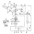
図1に一実施例の赤外顕微鏡の全体の光学系を示す。ただし、ここでは、ATRプリズムの図示は省略し、後の図2で説明する。
2は赤外測定を行なう際の測定モードを透過モードか反射モードかに切り換える透過/反射切換え鏡であり、透過/反射切換え鏡2には図示されていないFTIR(フーリエ変換赤外分光光度計)の干渉計から赤外光が導かれる。赤外反射分光測定モードのために切換え鏡2からの赤外光をカセグレン鏡からなる反射対物鏡10の光軸上に導くために、平面鏡4、球面鏡6及びハーフミラー8が設けられている。反射対物鏡10の焦点が試料上の位置14にくるように、反射対物鏡10の下部には試料ステージ12が設けられている。
試料ステージ12はステージ移動制御部50により水平面内でのX,Y方向に移動させられる。
FIG. 1 shows the entire optical system of an infrared microscope according to one embodiment. However, the ATR prism is not shown here and will be described later with reference to FIG.
Reference numeral 2 denotes a transmission / reflection switching mirror for switching the measurement mode when performing infrared measurement between the transmission mode and the reflection mode. FTIR (Fourier transform infrared spectrophotometer) not shown in the transmission / reflection switching mirror 2 Infrared light is guided from the interferometer. In order to guide the infrared light from the switching mirror 2 onto the optical axis of the reflection
The
赤外透過分光測定モードのために切換え鏡2からの赤外光を試料の下面から透過させるために、顕微鏡下部に平面鏡28、球面鏡30、ピンホール31、平面鏡32及びコンデンサ鏡34が設けられている。
A
反射対物鏡10で試料上に照射された赤外光による反射赤外光又は試料を透過した赤外光は再び反射対物鏡10で集光される。反射対物鏡10で集光された赤外光を赤外検出器のMCT検出器26に導くために、反射対物鏡10の上部に可変アパーチャ16、平面鏡20,22、及び軸外し楕円面鏡24が設けられている。
The reflected infrared light by the infrared light irradiated on the sample by the
可視反射観測モードで試料に可視光を照射するために、上部にハロゲンランプ36、レンズ系38、反射照明光導入用ハーフミラー40が設けられており、ハーフミラー40から平面鏡18、反射対物鏡10を経て可視光が試料に入射する。可視透過観測モードで試料に可視光を透過させるため、下部にハロゲンランプ42、透過照明光導入用平面鏡43が設けられており、平面鏡43から平面鏡32、コンデンサ鏡34を経て可視光が試料を透過する。
In order to irradiate the sample with visible light in the visible reflection observation mode, a
試料ステージ12及び反射対物鏡10の部分を図2に示す。試料ステージ12上に載置された試料54上にATRプリズム60が配置されている。ATRプリズム60は試料側に球面状接触面をもち、プリズムホルダ62に保持されている。ATRプリズム60の直径は2〜5mm程度である。プリズムホルダ62は水平方向にスライドできるようになっており、ATRプリズム60を試料54から外した可視観測モード又はプリズムを使用しない通常の赤外測定モード(a)と、ATRプリズム60を試料54に接触させたATR測定モード(b)とに切り替えることができるようになっている。
The
図1に戻って説明すると、52は記憶部で、プリズム60を介さない観測モードでの試料観測位置と、ATR測定モードでの試料測定位置とのずれ量を記憶しているものである。ステージ移動制御部50は、ATR測定モード時には試料観測位置と試料測定位置とが一致するように記憶部52に記憶されているずれ量だけ試料ステージ12を移動させるように、試料ステージ12の移動を制御する。
Returning to FIG. 1,
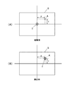
次に、図3により本実施例の動作を説明する。
通常の赤外顕微鏡測定(透過、正反射)では測定対象を顕微鏡視野の中央に移動させ、測定対象の大きさに合わせてアパーチャ16を開閉、回転させる。それにより、アバーチヤ開口部にある測定対象を透過又は反射した光のみが検出器26に到達し、それ以外の光は遮蔽されるため、測定対象のスペクトルが得られる。アパーチャ16の開口中心と観測視野の中心とにずれがあっても、観測においてアパーチャ16の状態を確認できるため、それに合わせて測定対象の位置を調整することができる。
Next, the operation of this embodiment will be described with reference to FIG.
In normal infrared microscope measurement (transmission, regular reflection), the measurement object is moved to the center of the microscope field, and the
それに対し赤外顕微鏡−ATR測定では、図3(A)に示されるように、アパーチャ16の設定とは別にプリズム60と接触した位置のスペクトルが得られるため、観測視野S中心又はアパーチャ開口中心(図中で符号Tで示された位置)とプリズム60の接触位置中心(図中で符号Aで示された位置)とが一致している場合は測定対象を正確に測定することができるが、両者に測定対象以上のずれがある場合は測定対象と異なった位置の測定をすることになり、正確なスペクトルが得られない。
On the other hand, in the infrared microscope-ATR measurement, as shown in FIG. 3A, a spectrum at a position in contact with the
本発明では、あらかじめ確認しておいた両者のずれ(X,Y)を記憶部52に記憶させておき、試料ステージ12を自動的に移動させて、(B)に示されるように補正するため、常に観測視野S中心又はアパーチャ開口中心Tとプリズム60の接触位置中心Aとが一致した状態を実現し、その結果、測定対象の正確な測定が行なえるようになる。
In the present invention, the deviation (X, Y) between the two confirmed in advance is stored in the
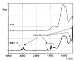
図4に、本実施例により、ガラス上に直径10μmの樹脂ビーズ(スチレン系)を乗せた試料を測定したスペクトルを示す。測定に用いたATR対物鏡は試料との接触面が曲面のゲルマニウムプリズムを搭載したもので、その空間分解能は約20μmのものである。このため、ビーズの測定結果はガラスによる影響を受けてはいるものの、はっきりとスチレン系のATRスペクトルを表している。 FIG. 4 shows a spectrum obtained by measuring a sample in which resin beads (styrene-based) having a diameter of 10 μm are placed on glass according to this example. The ATR objective mirror used for the measurement is equipped with a germanium prism having a curved contact surface with the sample, and has a spatial resolution of about 20 μm. For this reason, although the measurement result of beads is influenced by glass, it clearly shows a styrene-based ATR spectrum.
ATRプリズムによる測定位置を確定する方法の実施例を説明する。
図5(A)に示すように、プリズムの空間分解能よりも幅の小さい線状の試料70を顕微鏡の試料ステージ12上に固定し、試料ステージ12を動かすことによりその線状試料70の幅方向に移動させ、各位置でのATRスペクトルを測定していく。図で四角の枠は観察視野を表わしており、試料ステージ12の移動により線状試料70が矢印の方向に移動していく。移動量は線状試料70の線幅と同じかそれよりも小さくする.移動と測定を繰り返すことにより線状試料のATRスペクトルが得られる位置を探す。線状試料のATRスペクトルが得られる位置が確認できたら、そのときの線状試料のある位置(線上)70aに実際に測定する位置が存在する。そのときの試料ステージ12の座標を求めておく。
An embodiment of a method for determining the measurement position by the ATR prism will be described.
As shown in FIG. 5A, a
次に、(B)に示されるように、試料54を90°回転させることにより線状試料70を90°回転させ、同様の操作を繰り返して再度線状試料70のATRスペクトルが得られる位置70bを確認し、そのときの試料ステージ12の座標を求めておく。
以上の結果、得られた2つの線70aと70bの交わる点がプリズム60が試料と接触し実際に測定するポイントである。その位置は上の(A),(B)の2つのステップで得られた試料ステージの座標から求めることができる。
Next, as shown in (B), the
As a result of the above, the point where the two
線状試料としては、ラップフィルム(厚さ約10μm)や厚さ10μm前後の層を持つ多層フィルムをエポキシなどの樹脂で包埋し、ミクロトームなどで切断して作製したフィルム断面を用いることができる。フィルムの種類は特に問わない。フィルムのスペクトルと隣り合った物質のスペクトルとの違いが明確なものであればよい。また、フィルターなどの上にプレスされた繊維でも同様に使える。 As a linear sample, a film cross section produced by embedding a wrap film (thickness of about 10 μm) or a multilayer film having a thickness of about 10 μm with a resin such as epoxy and cutting with a microtome or the like can be used. . The type of film is not particularly limited. It is sufficient that the difference between the spectrum of the film and the spectrum of the adjacent substance is clear. It can also be used in the same way with fibers pressed on a filter.
図6は塩化ビニリデンフィルムF(厚さ約10μm、幅約50μm)を2種類のエポキシ系樹脂R1,R2で包埋し、ミクロトームで幅方向に切断して断面が出るように作製した線状試料の顕撤鏡写真であり、枠で囲まれた試料(包埋されている塩化ビニリデンフィルム断面)のサイズは10μm×50μmである。 FIG. 6 shows a linear sample prepared by embedding a vinylidene chloride film F (thickness of about 10 μm and width of about 50 μm) with two types of epoxy resins R1 and R2, and cutting in the width direction with a microtome. The size of the sample (embedded vinylidene chloride film cross section) surrounded by a frame is 10 μm × 50 μm.
図7はこの線状試料をフィルムの幅方向に移動させて得られるATRスペクトルを示したものである。包埋樹脂1,2とフィルムで識別できるスペクトルが得られており、この線状試料を用いることにより、図5に示した方法でATR測定モードでの測定位置を求めることができる。
プリズムを介さない観測モードで、可視光により、又は赤外光により試料観測位置を求める方法も、図5と同様に行なうことができる。
FIG. 7 shows an ATR spectrum obtained by moving the linear sample in the width direction of the film. The spectrum which can be discriminated by the embedding
A method of obtaining the sample observation position by visible light or infrared light in the observation mode not via the prism can be performed in the same manner as in FIG.
本発明赤外顕微鏡を用いた赤外分光分析は、物質の同定分析のために広く利用することができる。例えば化学物質、医薬品、電子材料など、有機物に限らず、無機物に対しても広く利用することができる。 Infrared spectroscopic analysis using the infrared microscope of the present invention can be widely used for identification analysis of substances. For example, it can be widely used not only for organic substances such as chemical substances, pharmaceuticals, and electronic materials, but also for inorganic substances.
10 反射対物鏡
12 試料ステージ
14 反射対物鏡の焦点位置
16 アパーチャ
26 赤外検出器
46,48 接眼レンズ
50 ステージ移動制御部
52 記憶部
70 線状試料
DESCRIPTION OF
Claims (3)
前記プリズムを介さない観測モードで、プリズムの空間分解能よりも幅の小さい線状試料を観測し、前記線状試料が観察視野中心を横切るように試料ステージを位置決めしたときの試料ステージの座標と、その状態から試料を90°回転させ、再び前記線状試料が観察視野中心を横切るように試料ステージを位置決めしたときの試料ステージの座標とから試料観測位置座標を求めるステップと、
ATR測定モードで前記線状試料を測定し、前記線状試料をその幅方向に走査して線状試料が検出されたときの試料ステージの座標と、その状態から試料を90°回転させ、再び前記線状試料をその幅方向に走査して線状試料が検出されたときの試料ステージの座標とからATR測定モードでの試料の測定位置座標を求めるステップとを備えて、
前記試料観測位置座標と前記測定位置座標との間のずれ量を求め、ATR測定モードでの試料測定時に試料観測位置座標とそのずれ量に基づいて試料の測定位置を確定する方法。 The prism is brought into contact with the sample on the sample stage, and infrared light is irradiated through the prism toward the sample surface at an incident angle equal to or greater than the total reflection critical angle, and the absorption spectrum of the infrared light reflected from the sample surface. In an infrared microscope having an ATR measurement mode for measuring
In the observation mode not via the prism, a linear sample having a width smaller than the spatial resolution of the prism is observed, and the sample stage coordinates when the sample stage is positioned so that the linear sample crosses the observation field center, and The sample is rotated by 90 ° from the state, and the sample observation position coordinates are obtained from the coordinates of the sample stage when the sample stage is positioned again so that the linear sample crosses the observation field center;
Measure the linear sample in the ATR measurement mode, scan the linear sample in its width direction, rotate the sample 90 degrees from the coordinates of the sample stage coordinates when the linear sample is detected, and again Scanning the linear sample in the width direction and obtaining the measurement position coordinates of the sample in the ATR measurement mode from the coordinates of the sample stage when the linear sample is detected,
A method of obtaining a deviation amount between the sample observation position coordinates and the measurement position coordinates and determining a measurement position of the sample based on the sample observation position coordinates and the deviation amount at the time of sample measurement in the ATR measurement mode .
前記プリズムを介さない観測モードでの試料観測位置と、ATR測定モードでの試料測定位置とのずれ量を記憶しておく記憶部と、
ATR測定モード時には前記試料観測位置と試料測定位置とが一致するように前記記憶部に記憶されているずれ量だけ前記試料ステージを移動させるステージ移動制御部とを備えたことを特徴とする赤外顕微鏡。 The prism is brought into contact with the sample on the sample stage, and infrared light is irradiated through the prism toward the sample surface at an incident angle equal to or greater than the total reflection critical angle, and the absorption spectrum of the infrared light reflected from the sample surface. In an infrared microscope having an ATR measurement mode for measuring
A storage unit for storing a deviation amount between the sample observation position in the observation mode not via the prism and the sample measurement position in the ATR measurement mode;
An infrared, comprising: a stage movement control unit configured to move the sample stage by a deviation amount stored in the storage unit so that the sample observation position and the sample measurement position coincide with each other in the ATR measurement mode. microscope.
Priority Applications (1)
| Application Number | Priority Date | Filing Date | Title |
|---|---|---|---|
| JP2003396524A JP4136911B2 (en) | 2003-11-27 | 2003-11-27 | Infrared microscope and measuring position determination method thereof |
Applications Claiming Priority (1)
| Application Number | Priority Date | Filing Date | Title |
|---|---|---|---|
| JP2003396524A JP4136911B2 (en) | 2003-11-27 | 2003-11-27 | Infrared microscope and measuring position determination method thereof |
Publications (2)
| Publication Number | Publication Date |
|---|---|
| JP2005156385A JP2005156385A (en) | 2005-06-16 |
| JP4136911B2 true JP4136911B2 (en) | 2008-08-20 |
Family
ID=34721941
Family Applications (1)
| Application Number | Title | Priority Date | Filing Date |
|---|---|---|---|
| JP2003396524A Expired - Fee Related JP4136911B2 (en) | 2003-11-27 | 2003-11-27 | Infrared microscope and measuring position determination method thereof |
Country Status (1)
| Country | Link |
|---|---|
| JP (1) | JP4136911B2 (en) |
Families Citing this family (6)
| Publication number | Priority date | Publication date | Assignee | Title |
|---|---|---|---|---|
| JP4773168B2 (en) * | 2005-09-13 | 2011-09-14 | 国立大学法人北海道大学 | Electrochemical infrared spectrometer |
| GB0608258D0 (en) * | 2006-04-26 | 2006-06-07 | Perkinelmer Singapore Pte Ltd | Spectroscopy using attenuated total internal reflectance (ATR) |
| JP4956322B2 (en) * | 2007-08-10 | 2012-06-20 | 東京電力株式会社 | Method for analyzing ions in water tree |
| JP4929106B2 (en) * | 2007-09-06 | 2012-05-09 | 日本分光株式会社 | Near-field fiber probe and near-field optical microscope |
| JP5115584B2 (en) * | 2010-05-20 | 2013-01-09 | 住友電気工業株式会社 | Sample cross-section formation method, fixing jig, and measurement method |
| WO2022173059A1 (en) * | 2021-02-15 | 2022-08-18 | 株式会社ニコン | Measurement device |
-
2003
- 2003-11-27 JP JP2003396524A patent/JP4136911B2/en not_active Expired - Fee Related
Also Published As
| Publication number | Publication date |
|---|---|
| JP2005156385A (en) | 2005-06-16 |
Similar Documents
| Publication | Publication Date | Title |
|---|---|---|
| JP4382098B2 (en) | Analysis method and analyzer | |
| JP3919749B2 (en) | Configuration and method of optical apparatus for differential refractive index measurement | |
| JP2006208016A (en) | Total reflection measuring instrument | |
| US5422703A (en) | Reflected light measuring method and reflected light measuring apparatus for a microscopic photometric system | |
| KR940002356B1 (en) | Method and apparatus for noncontact automatic focusing | |
| JP5363199B2 (en) | Microscopic total reflection measuring device | |
| JP2018119907A (en) | Method for adjusting measurement surface, method for measuring film thickness, and film thickness measuring device | |
| US5309214A (en) | Method for measuring distributed dispersion of gradient-index optical elements and optical system to be used for carrying out the method | |
| EP1212580B1 (en) | Method and apparatus for performing optical measurements of layers and surface properties | |
| NL2005902C2 (en) | Method and apparatus for surface plasmon resonance angle scanning. | |
| JP4136911B2 (en) | Infrared microscope and measuring position determination method thereof | |
| JPH0712717A (en) | Total reflection measuring device | |
| JP6485498B2 (en) | Total reflection microscope and adjustment method of total reflection microscope | |
| US7081957B2 (en) | Aperture to reduce sensitivity to sample tilt in small spotsize reflectometers | |
| JP4246599B2 (en) | Mapping measuring device | |
| US7294826B2 (en) | Bio-sensing apparatus | |
| JPH04116452A (en) | Microscopic infrared atr measuring apparatus | |
| US11624699B2 (en) | Measurement system capable of adjusting AOI, AOI spread and azimuth of incident light | |
| JP4713391B2 (en) | Infrared microscope | |
| JPH1144636A (en) | Total reflection absorption spectrum device | |
| JP3829663B2 (en) | Spectrophotometer | |
| JP2002310870A (en) | Hardness tester | |
| KR20230108732A (en) | Focus system for optical metrology devices | |
| JPH05164972A (en) | Infrared microscope | |
| JPH0472550A (en) | Optical device |
Legal Events
| Date | Code | Title | Description |
|---|---|---|---|
| A621 | Written request for application examination |
Free format text: JAPANESE INTERMEDIATE CODE: A621 Effective date: 20060206 |
|
| A977 | Report on retrieval |
Free format text: JAPANESE INTERMEDIATE CODE: A971007 Effective date: 20071207 |
|
| A131 | Notification of reasons for refusal |
Free format text: JAPANESE INTERMEDIATE CODE: A131 Effective date: 20071218 |
|
| A521 | Written amendment |
Free format text: JAPANESE INTERMEDIATE CODE: A523 Effective date: 20080215 |
|
| TRDD | Decision of grant or rejection written | ||
| A01 | Written decision to grant a patent or to grant a registration (utility model) |
Free format text: JAPANESE INTERMEDIATE CODE: A01 Effective date: 20080513 |
|
| A01 | Written decision to grant a patent or to grant a registration (utility model) |
Free format text: JAPANESE INTERMEDIATE CODE: A01 |
|
| A61 | First payment of annual fees (during grant procedure) |
Free format text: JAPANESE INTERMEDIATE CODE: A61 Effective date: 20080603 |
|
| R150 | Certificate of patent or registration of utility model |
Ref document number: 4136911 Country of ref document: JP Free format text: JAPANESE INTERMEDIATE CODE: R150 Free format text: JAPANESE INTERMEDIATE CODE: R150 |
|
| FPAY | Renewal fee payment (event date is renewal date of database) |
Free format text: PAYMENT UNTIL: 20110613 Year of fee payment: 3 |
|
| FPAY | Renewal fee payment (event date is renewal date of database) |
Free format text: PAYMENT UNTIL: 20110613 Year of fee payment: 3 |
|
| FPAY | Renewal fee payment (event date is renewal date of database) |
Free format text: PAYMENT UNTIL: 20120613 Year of fee payment: 4 |
|
| FPAY | Renewal fee payment (event date is renewal date of database) |
Free format text: PAYMENT UNTIL: 20130613 Year of fee payment: 5 |
|
| FPAY | Renewal fee payment (event date is renewal date of database) |
Free format text: PAYMENT UNTIL: 20130613 Year of fee payment: 5 |
|
| FPAY | Renewal fee payment (event date is renewal date of database) |
Free format text: PAYMENT UNTIL: 20140613 Year of fee payment: 6 |
|
| LAPS | Cancellation because of no payment of annual fees |