JP4136477B2 - Liquid dispensing device - Google Patents
Liquid dispensing device Download PDFInfo
- Publication number
- JP4136477B2 JP4136477B2 JP2002173768A JP2002173768A JP4136477B2 JP 4136477 B2 JP4136477 B2 JP 4136477B2 JP 2002173768 A JP2002173768 A JP 2002173768A JP 2002173768 A JP2002173768 A JP 2002173768A JP 4136477 B2 JP4136477 B2 JP 4136477B2
- Authority
- JP
- Japan
- Prior art keywords
- liquid
- plunger
- discharge
- valve
- block
- Prior art date
- Legal status (The legal status is an assumption and is not a legal conclusion. Google has not performed a legal analysis and makes no representation as to the accuracy of the status listed.)
- Expired - Fee Related
Links
Images

Description
【0001】
【産業の属する技術分野】
本発明は、あらゆる粘度の液体、たとえば、水、アルコールといった低粘性物質から、接着剤、ペースト状もしくはクリーム状の工業用材料といった高粘調流体にいたるまでの、液体を高速に高精度に吐出する方法および装置に関するものである。
【0002】
【従来の技術】
従来、液体を定量に吐出する装置においては、(1)調圧された圧縮空気を貯留容器内の液体に所望時間だけ適用して、ノズル先端の吐出口から所望量の液体を吐出する、Air式吐出装置、(2)貯留容器内の液体に液密に配設したプランジャを移動させて前記液体を加圧し、ノズル先端の吐出口から所望量の液体を吐出する、プランジャ式吐出装置、(3)貯留容器とノズルとの間にシリンダを設け、このシリンダ内に設けられた複数の貫通孔は一の貫通孔に一のプランジャが進退するよう施されており、プランジャの退行移動により貯留容器から液体がシリンダ内に吸入され、プランジャの進行移動により液体がシリンダからノズルへ排出される機構において、前記複数のプランジャが順に液体に作用して液体を加圧することにより、ノズル先端の吐出口から所望量の液体を吐出する、多連プランジャポンプ式吐出装置、など種々のものが開発されている。
【0003】
【発明が解決しようとする課題】
しかし、これらの技術では、現在求められているような高速なタクトタイムで、高精度にかつ定量性を維持して吐出することは不可能であった。
例えば、半導体製造におけるダイボンディング工程などにおいては、高性能を有する大きなサイズのデバイスの出現と、生産性を向上させるためのさらなる高タクト化の要求から、短時間に多量を吐出することが求められており、一方で高品質な製品が要求されることから高精度な吐出および精細な塗布が求められている。
このような要求を満たすために、前記従来技術にはいずれにも問題があった。
【0004】
たとえば、(1)Air式吐出装置は、液体を吐出する圧力源に空気圧を利用するが、空気圧は圧縮性に富んでいるため、短い時間に大きく圧力を変化させることが非常に難しく、従って高速なタクトで吐出することは不向きであった。
また、短時間に多量の液体を吐出する場合および特に吐出する液体が高粘度液剤である場合のように、液体に高い圧力を適用する必要がある場合においても、急激な貯留容器内の圧力変化が必要であるため、吐出時間を短くするには限界があり、また高速なタクトで吐出することができない問題があった。
【0005】
(2)のプランジャ式吐出装置は、貯留容器内の液体水頭付近に液密に配設されたプランジャが、貯留されている液体すべてを加圧して吐出する方式である。ここで、加圧される液体量は貯留容器内の残液量に依存されるから、液剤を加圧して所望圧力とするときの所望圧力到達時間は残液量が少量である場合は速く、残液量が多量である場合は遅くなる。このように、吐出時の圧力変化が貯留容器内の残液量によって異なるから、これに起因して吐出量のばらつきが生じる問題がある。
予め貯留する液体量を少量とすると、短い周期で貯留容器を交換する作業が必要となり作業効率が悪くなる問題が生じる。
【0006】
(3)多連プランジャポンプ式吐出装置においては、複数のプランジャが順に連続して液体を加圧動作する方式であるから、一のプランジャから他の一のプランジャに制御が移行する場合、液体は同時に2本のプランジャにより加圧されるために、与える力が均一とならず、よって吐出される液体には脈動が発生し流速が均一とならないという問題がある。
このため、この装置でワーク上に液体を線形状に塗布描画すると、線の幅および線高にムラ、歪みが発生し均一な塗布形状を形成させることができないから、高精細なパターン形状を描画する場合には、塗布形成させることが実質的に不可能である。
【0007】
本発明の目的は、液体の高速かつ高精度な定量吐出にかかるこれら問題を解消し、液体を高速に高精度に吐出する吐出方法およびその装置を提供することにある。
【0008】
【課題を解決するための手段】
本発明は、シリンダブロックに穿ったプランジャ室と該プランジャ室内を往復動するプランジャとからなり、吐出する液体を所望量に計量するポンプ部と、吸引および排出の液体流路を切り替えるバルブ部と、バルブ部の位置によりポンプ部と連通可能な、液体を貯留する貯留部と、液体を吐出する吐出口をそなえる吐出部と、による構成において、ポンプ部とバルブ部を連接して配設し、かつ、プランジャの最進出位置を、プランジャ前端面がバルブ部とポンプ部に接合する面としたことを特徴とする液体の定量吐出装置を要旨としている。
【0009】
上記のバルブ部を、貯留容器に連通する第一流路および吐出部に連通する第二流路とを有するバルブブロックを具える切換弁としており、その場合、本発明は、吐出する液体を所望量に計量するポンプ部と、吸引および排出の液体流路を切り替えるバルブ部と、バルブ部の位置によりポンプ部と連通可能な、液体を貯留する貯留部と、液体を吐出する吐出口をそなえる吐出部と、による構成において、プランジャを備えたシリンダが装着されたシリンダブロックで上記のポンプ部を構成したこと、上記のバルブ部を、貯留容器に連通する第一流路および吐出部に連通する第二流路とを有するバルブブロックを具える切換弁としたこと、ならびに、ポンプ部とバルブ部を連接して配設したことを特徴とする液体の定量吐出装置を要旨としている。
【0010】
上記の切換弁を、スライド型の切換弁としており、その場合、本発明は、吐出する液体を所望量に計量するポンプ部と、吸引および排出の液体流路を切り替えるバルブ部と、バルブ部の位置によりポンプ部と連通可能な、液体を貯留する貯留部と、液体を吐出する吐出口をそなえる吐出部と、による構成において、プランジャを備えたシリンダが装着されたシリンダブロックで上記のポンプ部を構成したこと、上記のバルブ部を、貯留容器に連通する第一流路および吐出部に連通する第二流路とを有するバルブブロックを具えるスライド型の切換弁としたこと、ならびに、ポンプ部とバルブ部を連接して配設したことを特徴とする液体の定量吐出装置を要旨としている。
【0011】
シリンダブロックとバルブブロックとを密着かつ滑合するように配設することによりポンプ部とバルブ部を連接して配設しており、その場合、本発明は、吐出する液体を所望量に計量するポンプ部と、吸引および排出の液体流路を切り替えるバルブ部と、バルブ部の位置によりポンプ部と連通可能な、液体を貯留する貯留部と、液体を吐出する吐出口をそなえる吐出部と、による構成において、プランジャを備えたシリンダが装着されたシリンダブロックで上記のポンプ部を構成したこと、上記のバルブ部を、貯留容器に連通する第一流路および吐出部に連通する第二流路とを有するバルブブロックを具えるスライド型、一方向回転型、または往復動平滑な滑り面を持つ回転型切換弁としたこと、ならびに、シリンダブロックとバルブブロックとを密着かつ滑合するように配設することによりポンプ部とバルブ部を連接して配設したことを特徴とする液体の定量吐出装置を要旨としている。
【0012】
【発明の実施の形態】
プランジャの後退動作により貯留容器から液体をプランジャ室に吸引し、前記プランジャの進出動作により前記液体をプランジャ室からノズルに排出する液体の定量吐出方法において、一回の吐出をプランジャの一回の吸入動作および一回の排出動作で行うことを特徴とする。液体は同時に複数本のプランジャにより加圧させることが無いから、液体に適用する加圧力が一定となり、よって吐出される液体に脈動が発生せず、流速が均一となる。このため、ワーク上に液体を線形状に塗布描画しても、線の幅および線高にムラ、歪みが発生せず、均一な塗布形状を形成させることができ、高精細なパターン形状を塗布形成させることができる。さらに、一回の吐出を一回のプランジャの移動で行うので、吐出される液体に脈動が無く、一定した流速で液体を吐出させることが可能であることから、所望する描画形状を均一かつ高精細に塗布形成させることができる。
【0013】
また、吐出とは、液体を加圧して誘起された液体と大気圧との圧力差によってノズルから液体が流出することであるから、圧力差を効果的に誘起するためには、加圧される液体の体積は少量であるほど好ましく、より急峻に液体圧力を上昇させることができ、短時間に多量の液体を吐出する場合および特に吐出する液体が高粘度液剤である場合に効果的である。したがって、複数回の吐出量に相当する液体量を加圧することよりも、一回の吐出量をプランジャ室内に液体を吸引して加圧することが好ましい。より好ましくは、プランジャの液体排出終了後のプランジャ室内には液体残量が無いことである。一回に吐出する量の液体をプランジャ室に吸入し、プランジャ室内の前記液体をプランジャの移動により圧力を適用させて吐出することから、加圧する液体量を最小限にすることが可能であり、よって液体に起因する影響を効果的に排除ならしめ、さらには液体を加圧してから液体がノズルより吐出されるまでの時間を大幅に短縮することが可能であり、高速な吐出を可能とする。
【0014】
ここで、プランジャの液体吸入開始位置と液体排出終了位置を吐出毎で等しくすることが好ましい。吐出毎の加圧する液体量を常に一定ならしめることは、加圧される液体量が貯留容器内の残液量に依存されることが無く、吐出時のプランジャが液体を加圧するときの液体圧力が上昇するプロセスを吐出毎に等しくすることができるから、貯留容器内の残液量に依存する吐出量のばらつきが無い。より好ましくは、さらに吐出毎のプランジャの液体吐出開始位置を同一の位置に、かつ吐出毎のプランジャの液体吐出終了位置を同一の位置にする。吐出毎の吐出開始および吐出終了におけるプランジャの位置が常に一定であることから、液体圧縮量が容器に貯留された液体量に依存されず常に一定となり、安定した高精度な吐出を行うことができる。さらに好ましくは、さらに吐出毎のプランジャの液体吸入開始位置を同一の位置に、かつ吐出毎のプランジャの液体吸入終了位置を同一の位置にする。
【0015】
具体的な装置構成は、液体を吐出するノズルと、液体を貯留する貯留容器と、内部にプランジャ室を有するシリンダブロックと、前記プランジャ室に内接して進退するプランジャと、プランジャを駆動する駆動手段と、プランジャ室と貯留容器またはノズルとを連通する切換弁と、を具える液体定量吐出装置である。この装置では、駆動手段に連結されたプランジャが内壁に接して進退移動し、プランジャが吐出量に等しい量だけ退行移動して貯留容器よりプランジャ室内に液体を吸入し、プランジャが吐出量に等しい量だけ進行移動してプランジャ室からノズルへ液体を排出することにより吐出を行う。このとき切換弁は、プランジャが後退移動してプランジャ室内に液体を吸入するときはプランジャ室と貯留容器を連通し、プランジャが進出移動してプランジャ室内から液体を排出するときはプランジャ室とノズルを連通するよう作動する。
【0016】
貯留容器と切換弁とを液送管を介して連通することにより、液剤貯留部と吐出機構部とを分離することができるため、取り扱いやすい場所に貯留容器を配置することが可能であり、たとえば、貯留容器内の液体の残量が少なくなった場合に、液体貯留容器に液体を補充する、または予め液体が充填されている貯留容器ごと交換する作業を容易に行うことが可能となる。さらには、容器内に貯留する液体量は使用する液体のポットライフや一日の作業量から考察して、計画的に適切な量を貯留しておくことができるため、一日の作業における液体の補充作業を不用とすることも、適宜補充することも可能である。
【0017】
さらに、ノズルと切換弁とを液送管を介して連通することにより、吐出機構部と吐出口を分離することができるため、吐出機構部は固定部に設置し、ノズルを可動部、たとえばロボットに搭載して作業することが可能となるため、可動部を極めて軽量に構成することができる。これにより塗布作業、たとえばワーク表面上に所望するパターン形状に塗布する描画作業を極めて高速に行うことが可能となる。
【0018】
貯留容器内の液体が高粘性流体である場合、またはプランジャ室内に速やかに液体を吸引させる場合などには、貯留容器の液体をプランジャ室に液送するためにプランジャの後退移動による吸引力を補助するために貯留容器内の液体を加圧する加圧装置を具えることが好ましい。
【0019】
切換弁はスライド型の切換弁とすることができる。好ましくは、切換弁を、貯留容器とを連通する第一流路およびノズルとを連通する第二流路とを有しスライドして連通する部位を切換えるバルブブロックを具えるスライド弁とする。前記第一流路と第二流路は隣接するほど、切換時のロスタイムを短縮することができ高速なタクトタイムで吐出することができる。
【0020】
駆動手段および/または切換弁が、制御部の信号に基づいて動作することができる。好ましくは、吐出時においてはプランジャがノズルに連通するよう切換弁を制御し、さらに駆動手段を制御して液体を加圧し、また吸引時においてはプランジャが貯留容器と連通するよう切換弁を制御し、さらに駆動手段を制御して液体を吸引する。
【0021】
プランジャの本数は複数とすることができる。このとき、複数回の吐出においては、毎回異なったプランジャで行うことができるから、プランジャのいずれか一の吐出動作にあたって、他のプランジャが吸引または停止動作することにより、次の吐出時には、液体を吸引したプランジャが液体を速やかに吐出することができるから、効果的に液体の吸引にかかる時間を不用ならしめ、より高速なタクトタイムができる。
【0022】
さらには、駆動手段をプランジャの数と等しくすることが可能である。
また、プランジャを独立して制御を可能とすることができる。このとき、一のプランジャが液体を吐出するときのプランジャの吐出作動速度と、他のプランジャが液体をプランジャ室内に吸引するときの吸引作動速度と、を異なる速度に容易に調整可能であるから、複数のプランジャのうち一のプランジャが吐出に携わるときには吐出に好適な、吸引に携わるときには吸引に好適な速度とすることが可能であり好ましい。
【0023】
さらに、本発明の、液体吐出装置は、液体を吐出するノズルと、液体を貯留する貯留容器と、プランジャポンプと、プランジャポンプを駆動する駆動手段と、プランジャ室と貯留容器またはノズルとを連通する切換弁とを具え、プランジャポンプを構成するシリンダブロックと切換弁を構成するバルブブロックとを密着かつ滑合するように配設したことを特徴とする。ポンプ部とバルブ部を連接して配設し、かつ、プランジャの先端位置が、バルブブロックとシリンダブロックとの接合する面にあるときに、吸入動作を開始し、および吐出動作を完了するので余剰量の液体を圧縮させることなく、必要最低限の液体を加圧することが可能となり、液体を高い応答性で制御することができ、従って、高速なタクトで吐出することができ、また、プランジャ先端位置が吐出毎に常に一定であるから、高精度に吐出することができる。
【0024】
したがって、ポンプ部の構成部品であるプランジャの進退移動、およびそれに伴うバルブ部の構成部品であるバルブブロックの移動で液体の排出および吸引を切換え、詳しくはバルブ部の構成部品であるバルブブロックの位置がポンプ部と液体貯留部が連通する位置にあるときに、プランジャが吐出量に相当する位置まで退行移動して貯留容器から液体をプランジャ室内に移動させ、プランジャを前記退行移動を開始した位置まで進出移動させてノズル先端から液体を吐出させるべく構成し、このとき、退行開始時および吐出完了時のプランジャの先端位置を、バルブブロックとシリンダブロックの接合する面とする。
【0025】
ここで、液体はわずかではあるが圧縮性があり、加圧すると体積を減少させる。つまり、液体を加圧するには、液体を圧縮させる必要があり、加圧する液体量が多ければ多いほど急峻な圧力上昇を起こすことが難しくなる。例えば、当該装置においては加圧すべき液体量が多ければ多いほどプランジャの移動速度を上げなければ圧力上昇プロセスが等しくならない。つまり、圧縮すべき液体量が少なければ僅かなプランジャの進退移動量で圧力上昇が可能である。したがって、前記退行開始時および吐出完了時のプランジャの先端位置を、バルブブロックとシリンダブロックの接合する面とすることで、余剰の液体をプランジャ室内に貯留することがなく、必要最低量の液体を加圧することが可能となる。
【0026】
また、必要最低量の液体量に圧力を作用させるから、プランジャの動作に応じてノズル先端から液体が吐出され、たとえば吐出完了後プランジャが停止しているにもかかわらずノズル吐出口よりだらだらと液体が吐出され続けるようなことがなく、圧縮した液体の膨張に起因する吐出完了の遅れ、ひいては液ダレを排除することができ、高応答性で液体を制御することが可能となる。
また、このように常にプランジャ先端の液体吸引開始位置、および液体吐出完了位置を一定の位置とすることで、加圧される液体も、プランジャ先端からノズル先端までの液体量が一定の量になるから、圧力バッファの圧縮量が常に一定した量となり、従って、吐出毎の液体量が安定し、精度良い吐出が可能となる。
【0027】
さらに、一回の吐出は一つのプランジャの一回の進出移動で行われるから、ノズル先端より吐出される液体には脈動が無い。また、プランジャ室内に吸入された液体はすべてプランジャ室内から排出されるから、プランジャ付近に滞留する液体がなく、長時間滞留した液体がプランジャ室内で変性してしまうことがない。例えば接着剤では固化してしまいプランジャが固定されてしまう、といったことがない。
【0028】
【作用】
ポンプ部の構成部品であるプランジャの進退移動、およびそれに伴うバルブ部の構成部品であるバルブブロックの移動で液体の排出および吸引を切換え、詳しくはバルブブロックの位置がポンプ部と液体貯留部が連通する位置にあるときに、プランジャが吐出量に相当する位置まで退行移動して貯留容器から液体をプランジャ室内に吐出する量だけ吸引し、その後バルブブロックをポンプ部とノズル部とが連通する位置に移動させ、プランジャを前記退行移動を開始した位置まで進出移動させてノズル先端から液体を吐出させる。このとき、退行開始時および吐出完了時のプランジャの先端位置を、バルブブロックとシリンダブロックの接合する面とする。
したがって、前記退行開始時および吐出完了時のプランジャの先端位置を、バルブブロックとシリンダブロックの接合する面とすることで、余剰の液体をプランジャ室内に貯留することがなく、必要最低量の液体を加圧することが可能となる。
【0029】
また、必要最低限の液体量に圧力を作用させるから、プランジャの動作に応じてノズル先端から液体が吐出され、たとえば吐出完了後プランジャが停止しているにもかかわらずノズル吐出口よりだらだらと液体が吐出され続けるようなことがなく、圧縮した液体の膨張に起因する吐出完了の遅れ、ひいては液ダレを排除することができ、高応答性で液体を制御することが可能となる。
また、このように常にプランジャ先端の液体吸引開始位置、および液体吐出完了位置を一定の位置とすることで、加圧される液体も、プランジャ先端からノズル先端までの液体量が一定の量になるから、圧力バッファの圧縮量が常に一定した量となり、従って、吐出毎の液体量が安定し、精度良い吐出が可能となる。
【0030】
さらに、一回の吐出は一のプランジャの一回の進出移動で行われるから、ノズル先端より吐出される液体には脈動が無い。
また、プランジャ室内に吸入された液体はすべてプランジャ室内から排出されるから、プランジャ付近に滞留する液体がなく、長時間滞留した液体がプランジャ室内で変性してしまうようなことがない。例えば接着剤では固化してしまいプランジャとプランジャ室が固定されてしまう、といったことがない。
【0031】
このように、ポンプ部とバルブ部を連接して配設し、かつプランジャの先端位置が、バルブブロックとシリンダブロックとの接合する面にあるときに吸入開始および吐出完了することができるから、余剰量の液体を圧縮させること無く、つまり必要最低限の液体を加圧することが可能となり、液体を高い応答性で制御することができ、従って、高速なタクトで吐出することができる。
また、プランジャ先端位置が吐出毎に常に一定であるから、高精度に吐出することができる。
なお、本願発明では、制御手段によるプランジャの停止位置を調整することにより、サックバック動作させることができることはいうまでもない。
【0032】
【実施例】
本願発明の詳細を実施例で説明する。本願発明はこれら実施例によって何ら限定されるものではない。
【0033】
実施例1
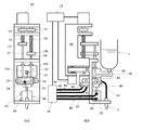
図1、2にもとづいて、本発明の1実施例を説明する
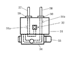
図中31は、ブロック状の金属材料にプランジャ室A31a,プランジャ室B31bを形成する円筒形の貫通孔を穿ったシリンダブロックである。プランジャ室A31a、プランジャ室B31bには、プランジャロッドA27とプランジャロッドB28が進退自在に嵌装されており、各プランジャロッドの行程は、最前進位置におけるプランジャロッドの前端面がシリンダブロック31の一側面と面一になるように設定されている。シリンダブロック31の前記貫通孔の開口を有する一側面には、バルブブロック34が密着かつ滑合するように配設されており、バルブブロック34は押部材35によりシリンダブロック31に圧接されており、両ブロック間の液体の漏洩を防止している。
なお、図中29、30はシリンダブロックとプランジャロッドとの間から液体が漏洩するのを防止するためのシール部である。
【0034】
バルブブロック34は、図示のように流路が形成されていて、シリンダブロック31とでスライド弁を構成し、貯留容器1とノズル2との間の流路を開閉して、ノズル2に供給する液体の制御をする。また、バルブブロック34のシリンダブロック31に圧接する面の流路が開口していない部分は、シリンダヘッドとして機能する。すなわち、スライド弁はバルブブロック34およびシリンダブロック35により構成されており、プランジャ室A31aと貯留容器1が連結するにあたってプランジャ室B31bとノズル2が連通するように、またプランジャ室A31aとノズル2が連通するにあたってはプランジャ室B31bと貯留容器1が連通するように、エア制御手段10からの信号に基づいてシリンダブロック31に対してバルブブロック34がスライドして切換作動する。
【0035】
また、バルブブロック34は、前記押部材35と前記シリンダブロック31との間で圧接しているから、バルブブロック34の摺動を円滑ならしめるため、バルブブロック34の、押部材35との接触面およびシリンダブロック31との接触面は摩擦係数を低くすることが好ましく、具体的には、接触する面積を小さくすることで行うことができる。
【0036】
モータA20は、ボールネジA23とギアA21を介して接続されている。
プランジャロッドA27はモータA20の回転動作によりプランジャ室A31aに内接して進退動作するよう、プランジャロッド取付板A25に付けられている。
プランジャロッドB28はボールネジB24の回転によりプランジャ室B31bに内接して進退動作するよう、プランジャロッド取付板B26に取りつけられており、プランジャロッドA27が進出移動するときにはプランジャロッドB28が退行移動するように、プランジャロッドA27が退行移動するときにはプランジャロッドB28が進出移動するように、ボールネジB24に連結したギアB22はギアA21と連結している。
【0037】
エアシリンダA36先端の押部材35は、シリンダブロックをエア制御手段10から供給されるエア圧力により加圧固定しているから、バルブブロック34は、シリンダブロック31および押部材35に密接して、相対的にスライド動作することができ、不要な液体の漏出を防止することができる。
エア制御手段10から常に一定のエア加圧力が供給されると、エアシリンダA36先端の押部材35は常に所望の力でバルブブロック34とシリンダブロック31を当接させることができる。加圧力としてバネ等を使用すると、材料等の変質および変形等により、バルブブロック34を抑えつける力が変位するため好ましくない。
さらに、エアシリンダA36を使用することは、万が一バルブブロック34とシリンダブロック31の接触面が磨耗してバルブブロック34の幅が小さくなっても、一定の加圧力に調圧されたエア圧力がエアシリンダA36に供給されていることから、磨耗前と同じ大きさの力でバルブブロック34をシリンダブロック31に当接可能であり、バルブブロック34とシリンダブロック31との接触面に間隙が発生せず、不要な液体の漏出を防止することができる。
【0038】
エアシリンダA36にはストッパーを取り付けて、バルブブロック34にシリンダブロック31と離れる方向の力がかかった場合に、エアシリンダA36が引っ込むのを防ぎ、バルブブロック34とシリンダブロック31とが離れないようにすることもできる。
バルブブロック34は、シリンダブロック31との接触面と平行にスライド動作し、プランジャ室A31aがノズル2と連通するときプランジャ室B31bが貯留容器1と連通するように、またプランジャ室B31bがノズル2と連通するときプランジャ室A31aが貯留容器1と連通するように、位置制御される。
このスライド動作は、エアシリンダB37をエア制御手段10が制御することにより行うことができる。
【0039】
エアシリンダB37の両端に接続された2本のバルブブロック支持アーム33の、アーム間の距離幅と同じ幅に形成されているバルブブロック34を前記2本の支持アーム33の間に挟み込んで、バルブブロック34をスライド動作させる。
【0040】
前記バルブブロック34は、接着固定されたものではなく、エアシリンダB37のバルブブロック支持アーム33と、エアシリンダA36の押部材35と、に加圧固定されているに過ぎないから、エアシリンダA36に圧力供給を断ち押し部材35がバルブブロック34の加圧を低下させると、簡単にバルブブロック34を取り外すことができ、バルブブロック34が磨耗したときの交換を容易とする。
【0041】
モータB38はボールネジC39と連結しており、モータB38の回転動作によりベースブロック49とサブブロック50との相対距離をボールネジC39の軸方向に変えることができる。
【0042】
ベースブロック49には、モータA20、ボールネジA23、ボールネジB24、プランジャロッドA27、プランジャロッドB28、プランジャロッド取付板A25、プランジャロッド取付板B26が固定されており、サブブロック50にはプランジャ室A31a、プランジャ室B31b、シリンダブロック31、ノズル2およびバルブブロック34が固定されているから、ベースブロック49とサブブロック50との相対距離をボールネジC39の回転により移動させることで、プランジャロッドA27およびプランジャロッドB28の相対距離を一定としたまま、プランジャロッドA27およびプランジャロッドB28とバルブブロック34との相対距離を調節できるから、微量吐出を行うようなプランジャロッドが僅かにしか変位しない場合には、プランジャロッド位置をバルブブロック34に近づけることが可能となり、不要な液体をシリンダ内に残留することを効果的に除去することができる。
【0043】
プランジャロッドの進退移動する最大ストローク量の中央が、プランジャロッドA27先端およびプランジャロッドB28先端が揃う位置であるとしたとき、最大ストロークを必要としない量を吐出する場合、例えば微量を吐出する場合には、プランジャロッドの最大ストローク量と比べて僅かな量しか進退動作をしない。このとき吐出終了時のプランジャロッド先端位置からバルブブロック34までの液体はバッファとして働くため、高速タクトで吐出を行う場合には特にバッファとなる液体は排除されることが好ましい。
【0044】
貯留容器1へは適宜液体を補充することができる。また、液体が貯留された別の貯留容器1に交換することも可能である。
エアシリンダA36およびエアシリンダB37はエア制御手段10に接続されていて、必要に応じてエアを供給することができる。また、エア制御手段10とモータA20とモータB38とは、制御部11に接続されており、制御部11の信号に基づいて動作する。
【0045】
吐出作業は、
(1)プランジャロッドA27およびプランジャロッドB28の先端がシリンダブロックから等距離にある位置(揃う位置)に調節する。この位置を基礎位置とする。
(2)プランジャロッドA27を所望吐出量の半分の体積量だけモータA1を駆動して進出移動させる。このときモータA1の回転は、プランジャロッドB28が所望吐出量の半分の体積量だけ後退移動するように、ギアA21を介してギアB22に伝わる。
(3)このときのプランジャロッドA27の基準位置からの進出量は、前記所望とする量を吐出する場合においては最大であるから、前記プランジャロッドA27の先端位置をバルブブロック34に近づけるようにモータB38を駆動して、プランジャ室A31a内の液体残量が最小となるよう、好ましくはゼロとなるようにベースブロック49とサブブロック50の相対距離を調節する。
モータBの駆動により、プランジャロッドA27およびプランジャロッドB28は一体的に並進移動するから、前記プランジャロッドA27および前記プランジャロッドB28の相対距離は変わらない。
【0046】
(4)ここで、貯留容器1とプランジャ室A31aとを連通するように、すなわちノズル2とプランジャ室B31bが連通するようにバルブブロック34の位置を調節する。
(5)次に、プランジャロッドB28を所望吐出体積量だけモータA20を駆動して進出移動させる。このときモータA20の回転は、プランジャロッドA27が所望吐出体積量だけ後退移動するから、貯留容器1の液体がプランジャ室A31a内に吸引される。
(6)さらに、貯留容器1とプランジャ室B31bとを連通するように、すなわちノズル2とプランジャ室A31aが連通するようにバルブブロック34の位置を調節する。
(7)プランジャロッドA27を所望吐出体積量だけモータA20を駆動して進出移動させる。プランジャ室A31aには所望量の液体が充填されていたから、前記モータA20の駆動によりノズル2先端の吐出口から液体が吐出される。また、貯留容器1とプランジャ室B31bが連通しており、このときモータA20の回転によりプランジャロッドB28は所望吐出体積量だけ後退移動するから、貯留容器1の液体がプランジャ室B31b内に吸引される。
(8)以下4〜7の動作で液体が吐出される。
【0047】
このように、一のプランジャロッドの進出により吐出が行われると同時に、他の一のプランジャロッドが液体をプランジャ室内に吸引するから、高速なタクトで吐出作業を行うことができる。
【0048】
実施例2
上記実施例1では、単1のモータによって2つのプランジャロッドを駆動しているが、この実施例は、2つのプランジャロッド27、28それぞれにモータ60、61が接続され、さらに、貯留容器1からプランジャ室A31a、B31bに液体が速やかに充填できるよう、貯留容器1内の液体に空圧を適用した例であり、主な特徴は以下の通りである。
【0049】
(1)2つボールネジ23、24のそれぞれに、モータ60、61を接続しているので、2本のプランジャロッド27、28をそれぞれ独立して動かすことができる。これにより、吐出と吸入の速度を変化させることができるので、吸入に時間がかかるような液体において、吐出速度を変化させずに、充填速度を遅くすることが可能であり、液体に不適な吸引力を作用させることがなく、キャビテーションなどが発生するのを抑えることができる。
【0050】
(2)独立している2つのモータ60、61を同じ方向に回転させることによって、プランジャロッドA27とプランジャロッドB28との相対距離を一定にしたまま、プランジャロッドA27およびプランジャロッドB28とバルブブロック34との相対距離を調整できるから、本実施例2においては、図3に図示したような、ベースブロックとサブブロックに分けてこれをモータによってスライドさせることを不用とする。
【0051】
(3)貯留容器1からプランジャ室A31a、B31bに液体が速やかに吸入できるよう、貯留容器1内部の空気をエア制御手段10によって加圧することができることから、プランジャ室への液体の供給を高速とすることが可能となり、より高速なタクトタイムで吐出作業を行うことができる。高粘度液体を吐出する場合に効果が大きい。本発明において、貯留容器とシリンダブロックとを液送チューブを介して連通させることも可能である。この場合、貯留容器と装置本体とを離れた位置に設置することができるから、装置本体が作業者の手の届かない位置に設置されても、貯留容器を容易に交換することが可能となる。同様に、バルブブロックとノズルとを液送チューブを介して連通させることも可能である。
【0052】
実施例3
上記実施例1及び2では、切換弁にスライド型の切換弁を採用したが、この実施例は、切換弁に平滑な滑り面を持つ回転型切換弁を採用し、シリンダブロックに接する面に円弧状の流路を形成した円盤状の弁体を一方向に回転させるか反復回動させることにより、シリンダブロックのバルブブロックと密着する面に設けたポンプ部に連通する孔と、前記密着する面に設けた液体貯留容器に連通する孔と、前記密着する面に設けたノズルに連通する孔と、を円盤状の弁体に設けた円弧状の流路によって、ポンプ部と液体貯留容器が連通する状態と、ポンプ部とノズルが連通する状態とに切換動作をさせて、実施例1又は2と同様に流路を切換えるものである。
【0053】
上記の実施例のいずれも、2つのポンプ部を備えたものを説明したが、本願発明は、ポンプ部を1つにして、液体流路をプランジャ室と液体貯留容器とを連通するか又はプランジャ室とノズルとを連通するように切り換えるべく構成することも可能である。
また、プランジャ室をシリンダブロックに直接穿ったものを採用したが、シリンダブロックに穿った装着孔に別体のシリンダを嵌合してプランジャ室を形成することができ、加えて、シリンダブロックに加工しやすい材料を用い、シリンダブロックに穿った装着孔に別体のシリンダを嵌合してプランジャ室を形成し、バルブ部と密着する摺動面を硬質部材で形成してもよい。
なお、プランジャ室をシリンダブロックに直接形成したものでも、シリンダブロックのバルブ部に接触する面は摩耗が激しいので、バルブ部と密着する摺動面を硬質部材で形成してもよい。
【0054】
【発明の効果】
このように、ポンプ部とバルブ部を連接して配設し、かつプランジャの最進出位置を、プランジャの前端面がバルブ部とポンプ部に接合する面とすることで、余剰量の液体を圧縮させること無く、つまり必要最低限の液体を加圧することが可能となり、液体を高い応答性で制御することができ、従って、高速なタクトで吐出することができる。
また、プランジャ先端位置が吐出毎に常に一定であるから、高精度に吐出することができる。
【図面の簡単な説明】
【図1】実施例1の概略図である。
【図2】実施例1の要部拡大図である。
【図3】実施例2の概略図である。
【符号の説明】
1 貯留容器
2 ノズル
10 エア制御手段
11 制御部
20 モータA
21 ギアA
22 ギアB
23 ボールネジA
24 ボールネジB
25 プランジャロッド取付板A
26 プランジャロッド取付板B
27 プランジャロッドA
28 プランジャロッドB
29 シール部
30 シール部
31 シリンダブロック
31a プランジャ室A
31b プランジャ室B
32 貯留容器取付口
33 支持アーム
34 バルブブロック
35 押部材
36 エアシリンダA
37 エアシリンダB
38 モータB
39 ボールネジC
40 液送チューブA
41 エアシリンダBエアチューブ取付口1
42 エアシリンダBエアチューブ取付口2
43 エアチューブC
44 エアチューブD
45 エアシリンダAエアチューブ取付口1
46 エアシリンダAエアチューブ取付口2
47 エアチューブE
48 エアチューブF
49 ベースブロック
50 サブブロック
60 モータC
61 モータD[0001]
[Technical field to which industry belongs]
The present invention discharges liquids of all viscosities, for example, low viscosity substances such as water and alcohol, to high viscosity fluids such as adhesives, pastes, or creamy industrial materials at high speed and with high accuracy. Method and apparatus.
[0002]
[Prior art]
2. Description of the Related Art Conventionally, in a device that discharges liquid in a fixed amount, (1) Air is applied to a liquid in a storage container for a desired time, and a desired amount of liquid is discharged from a discharge port at the tip of the nozzle. (2) Plunger-type discharge device that pressurizes the liquid by moving a liquid-tight plunger to the liquid in the storage container and discharges a desired amount of liquid from the discharge port at the tip of the nozzle. 3) A cylinder is provided between the storage container and the nozzle, and a plurality of through holes provided in the cylinder are provided so that one plunger is advanced and retracted in one through hole. In the mechanism in which the liquid is sucked into the cylinder and the liquid is discharged from the cylinder to the nozzle by the forward movement of the plunger, the plurality of plungers act on the liquid in order to pressurize the liquid, Discharging a desired amount of liquid from the discharge port of the nozzle tip, multiple-plunger pump discharge device, various ones such as have been developed.
[0003]
[Problems to be solved by the invention]
However, with these techniques, it has been impossible to discharge with high accuracy and high quantitativeness while maintaining a fast tact time as currently required.
For example, in the die bonding process in semiconductor manufacturing, it is required to discharge a large amount in a short time due to the appearance of large-sized devices with high performance and the demand for higher tact to improve productivity. On the other hand, since a high-quality product is required, high-precision discharge and fine coating are required.
In order to satisfy such a requirement, the conventional techniques have problems.
[0004]
For example, (1) Air type discharge device uses air pressure as a pressure source for discharging liquid, but since air pressure is rich in compressibility, it is very difficult to change the pressure greatly in a short time, so high speed It was unsuitable to discharge with a short tact.
Even when a large amount of liquid is discharged in a short time and particularly when the liquid to be discharged is a high-viscosity liquid agent, it is necessary to apply a high pressure to the liquid. Therefore, there is a limit to shortening the discharge time, and there is a problem that the discharge cannot be performed with high-speed tact.
[0005]
The plunger-type discharge device (2) is a method in which a plunger disposed in a liquid-tight manner near the liquid head in the storage container pressurizes and discharges all the stored liquid. Here, since the amount of liquid to be pressurized depends on the amount of residual liquid in the storage container, the desired pressure arrival time when the liquid agent is pressurized to a desired pressure is fast when the residual liquid amount is small, If there is a large amount of residual liquid, it will be slow. Thus, since the pressure change at the time of discharge differs depending on the amount of remaining liquid in the storage container, there is a problem that the discharge amount varies due to this.
If the amount of liquid stored in advance is set to a small amount, an operation of exchanging the storage container at a short cycle is required, resulting in a problem that work efficiency deteriorates.
[0006]
(3) In the multiple plunger pump type discharge device, since a plurality of plungers sequentially pressurizes the liquid, when the control shifts from one plunger to the other plunger, the liquid is Since the pressure is simultaneously applied by the two plungers, the applied force is not uniform, and thus there is a problem in that the pulsation is generated in the discharged liquid and the flow velocity is not uniform.
For this reason, if liquid is applied and drawn on the workpiece in a linear shape with this device, unevenness and distortion occur in the line width and line height, and a uniform application shape cannot be formed. In this case, it is substantially impossible to form the coating.
[0007]
An object of the present invention is to provide a discharge method and apparatus for discharging a liquid at high speed and with high accuracy by solving these problems concerning high-speed and high-precision quantitative discharge of the liquid.
[0008]
[Means for Solving the Problems]
The present invention comprises a plunger chamber bored in a cylinder block and a plunger that reciprocates in the plunger chamber, a pump unit that measures the amount of liquid to be discharged to a desired amount, a valve unit that switches between suction and discharge liquid flow paths, In a configuration with a storage part for storing liquid and a discharge part having a discharge port for discharging liquid, which can communicate with the pump part depending on the position of the valve part, the pump part and the valve part are connected to each other, and The gist of the liquid dispensing apparatus is characterized in that the most advanced position of the plunger is the surface where the front end surface of the plunger is joined to the valve portion and the pump portion.
[0009]
The valve section is a switching valve including a valve block having a first flow path communicating with the storage container and a second flow path communicating with the discharge section. In this case, the present invention provides a desired amount of liquid to be discharged. A pump section for metering the liquid, a valve section for switching the liquid flow path for suction and discharge, a storage section for storing the liquid that can communicate with the pump section according to the position of the valve section, and a discharge section having a discharge port for discharging the liquid In the configuration of the above, the above-described pump unit is configured by a cylinder block equipped with a cylinder having a plunger, and the above-described valve unit is connected to the first flow path communicating with the storage container and the second flow communicating with the discharge unit. The gist of the liquid dispensing device is characterized in that it is a switching valve having a valve block having a passage, and the pump part and the valve part are connected to each other.
[0010]
The above-described switching valve is a slide-type switching valve. In this case, the present invention provides a pump unit that measures the amount of liquid to be discharged to a desired amount, a valve unit that switches a suction and discharge liquid flow path, In the configuration of the storage part that stores the liquid that can communicate with the pump part depending on the position, and the discharge part that includes the discharge port that discharges the liquid, the pump part is configured by a cylinder block in which a cylinder having a plunger is mounted. The above-described valve unit is a slide-type switching valve having a valve block having a first channel communicating with the storage container and a second channel communicating with the discharge unit, and a pump unit The gist of the liquid dispensing apparatus is characterized in that the valve portions are connected to each other.
[0011]
The cylinder block and the valve block are arranged so as to be in close contact with each other, and the pump unit and the valve unit are arranged to be connected. In this case, the present invention measures the liquid to be discharged to a desired amount. By the pump unit, the valve unit for switching the liquid flow path for suction and discharge, the storage unit for storing the liquid that can communicate with the pump unit depending on the position of the valve unit, and the discharge unit having a discharge port for discharging the liquid In the configuration, the pump unit is configured by a cylinder block to which a cylinder having a plunger is attached, the first flow path communicating with the storage container, and the second flow path communicating with the discharge section. A rotary type switching valve having a sliding block, a one-way rotating type, or a reciprocating smooth sliding surface, and a cylinder block and a valve block. It is summarized as dispensing system for a liquid, characterized in that arranged by connecting the pump unit and the valve unit by disposing in close contact and sliding fit and.
[0012]
DETAILED DESCRIPTION OF THE INVENTION
In the method of quantitative dispensing of liquid, in which the liquid is sucked from the storage container into the plunger chamber by the retreating operation of the plunger, and the liquid is discharged from the plunger chamber to the nozzle by the advancement operation of the plunger, It is characterized by performing the operation and one discharging operation. Since the liquid is not pressurized by a plurality of plungers at the same time, the applied pressure applied to the liquid is constant, so that no pulsation occurs in the discharged liquid and the flow rate becomes uniform. For this reason, even if the liquid is applied and drawn on the workpiece in a linear shape, the width and height of the line are not uneven or distorted, and a uniform applied shape can be formed, and a high-definition pattern shape can be applied. Can be formed. Furthermore, since one discharge is performed by one movement of the plunger, there is no pulsation in the discharged liquid, and it is possible to discharge the liquid at a constant flow rate. It can be finely applied and formed.
[0013]
Moreover, since the discharge means that the liquid flows out from the nozzle due to the pressure difference between the liquid induced by pressurizing the liquid and the atmospheric pressure, the liquid is pressurized in order to effectively induce the pressure difference. The smaller the volume of the liquid, the better. The liquid pressure can be increased more steeply, which is effective when a large amount of liquid is discharged in a short time and particularly when the liquid to be discharged is a high-viscosity liquid agent. Therefore, it is preferable to pressurize a single discharge amount by sucking the liquid into the plunger chamber rather than pressurizing a liquid amount corresponding to a plurality of discharge amounts. More preferably, there is no remaining liquid in the plunger chamber after completion of the plunger liquid discharge. Since the amount of liquid to be discharged at one time is sucked into the plunger chamber and the liquid in the plunger chamber is discharged by applying pressure by moving the plunger, it is possible to minimize the amount of liquid to be pressurized, Therefore, it is possible to effectively eliminate the influence caused by the liquid, and furthermore, it is possible to greatly shorten the time from the pressurization of the liquid until the liquid is discharged from the nozzle, thereby enabling high-speed discharge. .
[0014]
Here, it is preferable that the liquid suction start position and the liquid discharge end position of the plunger are made equal for each discharge. Making the amount of liquid to be pressurized at each discharge constant always means that the amount of liquid to be pressurized does not depend on the amount of remaining liquid in the storage container, and the liquid pressure when the plunger at the time of discharge pressurizes the liquid Since the process of increasing the amount can be made equal for each discharge, there is no variation in the discharge amount depending on the remaining liquid amount in the storage container. More preferably, the liquid discharge start position of the plunger for each discharge is set to the same position, and the liquid discharge end position of the plunger for each discharge is set to the same position. Since the position of the plunger at the start and end of each discharge is always constant, the liquid compression amount is always constant regardless of the amount of liquid stored in the container, and stable high-precision discharge can be performed. . More preferably, the liquid suction start position of the plunger for each discharge is set to the same position, and the liquid suction end position of the plunger for each discharge is set to the same position.
[0015]
A specific device configuration includes a nozzle for discharging liquid, a storage container for storing liquid, a cylinder block having a plunger chamber therein, a plunger inscribed and retracted in contact with the plunger chamber, and drive means for driving the plunger And a switching valve that communicates the plunger chamber with the storage container or nozzle. In this device, the plunger connected to the driving means moves forward and backward in contact with the inner wall, the plunger moves backward by an amount equal to the discharge amount, sucks liquid from the storage container into the plunger chamber, and the plunger is equal to the discharge amount. The liquid is discharged by discharging the liquid from the plunger chamber to the nozzle by moving forward only. At this time, the switching valve communicates the plunger chamber and the storage container when the plunger moves backward to suck the liquid into the plunger chamber, and when the plunger moves forward and discharges the liquid from the plunger chamber, the plunger chamber and the nozzle are connected. Operates to communicate.
[0016]
By connecting the storage container and the switching valve via the liquid feed pipe, the liquid agent storage part and the discharge mechanism part can be separated, so that the storage container can be disposed in an easy-to-handle place, for example, When the remaining amount of the liquid in the storage container is reduced, it is possible to easily perform the operation of replenishing the liquid storage container with the liquid or replacing the storage container filled with the liquid in advance. Furthermore, the amount of liquid stored in the container can be stored in a planned manner, considering the pot life of the liquid to be used and the daily work amount. It is possible to dispense with the replenishment work or to replenish appropriately.
[0017]
Further, since the discharge mechanism and the discharge port can be separated by communicating the nozzle and the switching valve via the liquid feed pipe, the discharge mechanism is installed in the fixed part, and the nozzle is moved to the movable part, for example, a robot. Therefore, the movable part can be made extremely lightweight. This makes it possible to carry out a coating operation, for example, a drawing operation for applying a desired pattern shape on the workpiece surface at a very high speed.
[0018]
When the liquid in the storage container is a highly viscous fluid, or when the liquid is quickly sucked into the plunger chamber, the suction force by the backward movement of the plunger is assisted to feed the liquid in the storage container into the plunger chamber. In order to do so, it is preferable to provide a pressurizing device for pressurizing the liquid in the storage container.
[0019]
The switching valve can be a slide type switching valve. Preferably, the switching valve is a slide valve having a first flow path that communicates with the storage container and a second flow path that communicates with the nozzle, and a valve block that slides and switches a portion that communicates. As the first flow path and the second flow path are adjacent to each other, the loss time at the time of switching can be shortened and the discharge can be performed with a high tact time.
[0020]
The driving means and / or the switching valve can operate based on a signal from the control unit. Preferably, the switching valve is controlled so that the plunger communicates with the nozzle at the time of discharge, the driving means is controlled to pressurize the liquid, and the suction valve is controlled so that the plunger communicates with the storage container at the time of suction. Further, the driving means is controlled to suck the liquid.
[0021]
The number of plungers can be plural. At this time, since a plurality of discharges can be performed with different plungers each time, in the discharge operation of any one of the plungers, the other plunger is sucked or stopped, so that the liquid is discharged at the next discharge. Since the sucked plunger can quickly discharge the liquid, the time required for effectively sucking the liquid can be made unnecessary, and a faster tact time can be achieved.
[0022]
Furthermore, it is possible to make the drive means equal to the number of plungers.
Further, the plunger can be controlled independently. At this time, the discharge operation speed of the plunger when one plunger discharges the liquid and the suction operation speed when the other plunger sucks the liquid into the plunger chamber can be easily adjusted to different speeds. It is preferable that one of the plurality of plungers is suitable for discharging when the plunger is engaged in discharging, and is preferable for suction when engaging in the suction.
[0023]
Furthermore, the liquid ejection device of the present invention communicates the nozzle that ejects the liquid, the storage container that stores the liquid, the plunger pump, the driving means that drives the plunger pump, the plunger chamber, and the storage container or nozzle. A switching valve is provided, and a cylinder block constituting the plunger pump and a valve block constituting the switching valve are arranged so as to be in close contact with each other and to slide together. When the pump unit and the valve unit are connected and the tip of the plunger is on the surface where the valve block and the cylinder block are joined, the suction operation is started and the discharge operation is completed. Without compressing the amount of liquid, it becomes possible to pressurize the minimum amount of liquid, and the liquid can be controlled with high responsiveness. Since the position is always constant for each discharge, it is possible to discharge with high accuracy.
[0024]
Therefore, liquid discharge and suction are switched by the forward / backward movement of the plunger, which is a component part of the pump unit, and the movement of the valve block, which is a component part of the valve unit, and the position of the valve block, which is a component part of the valve unit. When the pump unit and the liquid storage unit communicate with each other, the plunger moves backward to a position corresponding to the discharge amount, moves the liquid from the storage container into the plunger chamber, and moves the plunger to the position where the backward movement starts. Advance The nozzle is moved so that the liquid is discharged from the tip of the nozzle. At this time, the position of the tip of the plunger at the start of the retraction and at the completion of the discharge is the surface where the valve block and the cylinder block are joined.
[0025]
Here, the liquid is slightly compressible, but pressurizes to reduce the volume. That is, in order to pressurize the liquid, it is necessary to compress the liquid, and it becomes difficult to cause a steep pressure increase as the amount of liquid to be pressurized increases. For example, in this apparatus, the more the amount of liquid to be pressurized, the more the pressure increase process becomes equal unless the plunger moving speed is increased. That is, if the amount of liquid to be compressed is small, the pressure can be increased with a small amount of plunger movement. Therefore, by setting the tip position of the plunger at the start of retraction and at the completion of discharge as the surface where the valve block and the cylinder block are joined, excess liquid is not stored in the plunger chamber, and the necessary minimum amount of liquid is stored. It becomes possible to pressurize.
[0026]
In addition, since pressure is applied to the minimum required amount of liquid, the liquid is discharged from the nozzle tip according to the operation of the plunger. For example, the liquid is gently discharged from the nozzle discharge port even though the plunger is stopped after completion of the discharge. Thus, the discharge completion delay due to the expansion of the compressed liquid, and the liquid sag can be eliminated, and the liquid can be controlled with high responsiveness.
In addition, by constantly setting the liquid suction start position and the liquid discharge completion position at the plunger tip in this way, the amount of liquid to be pressurized from the plunger tip to the nozzle tip is also constant. Therefore, the compression amount of the pressure buffer is always a constant amount, so that the liquid amount for each discharge is stable and accurate discharge is possible.
[0027]
Further, since one discharge is performed by one advance movement of one plunger, the liquid discharged from the nozzle tip has no pulsation. Further, since all the liquid sucked into the plunger chamber is discharged from the plunger chamber, there is no liquid staying in the vicinity of the plunger, and the liquid staying for a long time is not denatured in the plunger chamber. For example, the adhesive does not solidify and the plunger is not fixed.
[0028]
[Action]
The discharge and suction of the liquid are switched by the forward / backward movement of the plunger, which is a component of the pump unit, and the movement of the valve block, which is the component of the valve unit, and the position of the valve block is in communication with the pump block. The plunger moves backward to a position corresponding to the discharge amount, sucks the liquid from the storage container by the amount to be discharged into the plunger chamber, and then moves the valve block to a position where the pump unit and the nozzle unit communicate with each other. Then, the plunger is moved forward to the position where the backward movement is started, and the liquid is discharged from the tip of the nozzle. At this time, the tip position of the plunger at the start of retraction and at the completion of discharge is defined as a surface where the valve block and the cylinder block are joined.
Therefore, by setting the tip position of the plunger at the start of retraction and at the completion of discharge as the surface where the valve block and the cylinder block are joined, excess liquid is not stored in the plunger chamber, and the necessary minimum amount of liquid is stored. It becomes possible to pressurize.
[0029]
In addition, since pressure is applied to the minimum amount of liquid, liquid is discharged from the nozzle tip according to the operation of the plunger. For example, the liquid is gently discharged from the nozzle discharge port even though the plunger is stopped after completion of discharge. Thus, the discharge completion delay due to the expansion of the compressed liquid, and the liquid sag can be eliminated, and the liquid can be controlled with high responsiveness.
In addition, by constantly setting the liquid suction start position and the liquid discharge completion position at the plunger tip in this way, the amount of liquid to be pressurized from the plunger tip to the nozzle tip is also constant. Therefore, the compression amount of the pressure buffer is always a constant amount, so that the liquid amount for each discharge is stable and accurate discharge is possible.
[0030]
Furthermore, since one discharge is performed by one advance movement of one plunger, the liquid discharged from the nozzle tip has no pulsation.
Further, since all the liquid sucked into the plunger chamber is discharged from the plunger chamber, there is no liquid staying in the vicinity of the plunger, and the liquid staying for a long time is not denatured in the plunger chamber. For example, the adhesive does not solidify and the plunger and the plunger chamber are not fixed.
[0031]
In this way, since the pump portion and the valve portion are connected and disposed, and when the tip end position of the plunger is on the surface where the valve block and the cylinder block are joined, the suction start and discharge can be completed. Without compressing the amount of liquid, that is, it is possible to pressurize the minimum necessary liquid, and the liquid can be controlled with high responsiveness, and therefore, it can be discharged at high speed.
Further, since the plunger tip position is always constant for each discharge, it is possible to discharge with high accuracy.
In the present invention, it goes without saying that the suck back operation can be performed by adjusting the stop position of the plunger by the control means.
[0032]
【Example】
The details of the present invention will be described in Examples. The present invention is not limited to these examples.
[0033]
Example 1
An embodiment of the present invention will be described with reference to FIGS.
In the figure,
In the figure, 29 and 30 are seal portions for preventing liquid from leaking from between the cylinder block and the plunger rod.
[0034]
The
[0035]
Further, since the
[0036]
The motor A20 is connected via a ball screw A23 and a gear A21.
The plunger rod A27 is attached to the plunger rod mounting plate A25 so as to move inward and backward with respect to the plunger chamber A31a by the rotation operation of the motor A20.
The plunger rod B28 is attached to the plunger rod mounting plate B26 so that the plunger rod B28 is moved inward and backward by rotating the ball screw B24, and when the plunger rod A27 moves forward, the plunger rod B28 moves backward. The gear B22 connected to the ball screw B24 is connected to the gear A21 so that the plunger rod B28 moves forward when the plunger rod A27 moves backward.
[0037]
Since the
When a constant air pressure is always supplied from the air control means 10, the
Furthermore, the use of the air cylinder A36 means that even if the contact surface between the
[0038]
A stopper is attached to the air cylinder A36 to prevent the air cylinder A36 from being retracted when a force is applied to the
The
This sliding operation can be performed by the
[0039]
A
[0040]
The
[0041]
The motor B38 is connected to the ball screw C39, and the relative distance between the
[0042]
A motor A20, a ball screw A23, a ball screw B24, a plunger rod A27, a plunger rod B28, a plunger rod mounting plate A25, and a plunger rod mounting plate B26 are fixed to the
[0043]
When the center of the maximum stroke amount that the plunger rod moves forward and backward is the position where the tip of the plunger rod A27 and the tip of the plunger rod B28 are aligned, when discharging an amount that does not require the maximum stroke, for example, when discharging a minute amount Moves forwards and backwards by a small amount compared to the maximum stroke of the plunger rod. At this time, the liquid from the plunger rod tip position at the end of the discharge to the
[0044]
The
The air cylinder A36 and the air cylinder B37 are connected to the air control means 10, and can supply air as required. The air control means 10, the
[0045]
The discharge work is
(1) Adjust the tip of plunger rod A27 and plunger rod B28 to a position where they are equidistant from the cylinder block. This position is the base position.
(2) The plunger rod A27 is moved forward by driving the motor A1 by a volume amount that is half the desired discharge amount. At this time, the rotation of the motor A1 is transmitted to the gear B22 via the gear A21 so that the plunger rod B28 moves backward by half the volume of the desired discharge amount.
(3) Since the amount of advancement of the plunger rod A27 from the reference position at this time is the maximum when the desired amount is discharged, the motor moves the tip position of the plunger rod A27 closer to the
By driving the motor B, the plunger rod A27 and the plunger rod B28 move in translation integrally, so the relative distance between the plunger rod A27 and the plunger rod B28 does not change.
[0046]
(4) Here, the
(5) Next, the plunger rod B28 is moved forward by driving the motor A20 by a desired discharge volume. At this time, the rotation of the motor A20 causes the plunger rod A27 to move backward by the desired discharge volume, so that the liquid in the
(6) Further, the position of the
(7) The plunger rod A27 is moved forward by driving the motor A20 by a desired discharge volume. Since the plunger chamber A31a is filled with a desired amount of liquid, the liquid is discharged from the discharge port at the tip of the
(8) The liquid is discharged by the following operations 4 to 7.
[0047]
In this way, discharge is performed by the advancement of one plunger rod, and at the same time, the other plunger rod sucks the liquid into the plunger chamber, so that the discharge operation can be performed with high-speed tact.
[0048]
Example 2
In the first embodiment, the two plunger rods are driven by a single motor. However, in this embodiment, the
[0049]
(1) Since the
[0050]
(2) By rotating the two
[0051]
(3) Since the air in the
[0052]
Example 3
In the first and second embodiments, a slide-type switching valve is used as the switching valve. However, in this embodiment, a rotary switching valve having a smooth sliding surface is used as the switching valve, and the surface in contact with the cylinder block is circular. A hole communicating with the pump portion provided on the surface of the cylinder block which is in close contact with the valve block of the cylinder block by rotating the disc-shaped valve body forming the arc-shaped flow path in one direction or repeatedly rotating, and the above-mentioned close contact surface The pump unit and the liquid storage container communicate with each other by an arc-shaped flow path provided in the disc-shaped valve body with a hole communicating with the liquid storage container provided in the plate and a hole communicating with the nozzle provided on the contact surface. The flow path is switched in the same manner as in the first or second embodiment by performing a switching operation between the state in which the pump unit and the nozzle communicate with each other.
[0053]
In any of the above-described embodiments, the one having two pump parts has been described. However, in the present invention, the pump part is used as one, the liquid flow path is connected to the plunger chamber and the liquid storage container, or the plunger It is also possible to switch the chamber and the nozzle so as to communicate with each other.
In addition, the plunger chamber is directly drilled in the cylinder block, but a separate cylinder can be fitted into the mounting hole drilled in the cylinder block to form the plunger chamber. In addition, the cylinder block is processed. It is also possible to use a material that is easy to do, fit a separate cylinder into the mounting hole bored in the cylinder block to form a plunger chamber, and form a sliding surface that is in close contact with the valve portion with a hard member.
Even if the plunger chamber is formed directly on the cylinder block, the surface of the cylinder block that contacts the valve portion is highly worn, and the sliding surface that is in close contact with the valve portion may be formed of a hard member.
[0054]
【The invention's effect】
In this way, the pump unit and the valve unit are connected and arranged, and the most advanced position of the plunger is the surface where the front end surface of the plunger is joined to the valve unit and the pump unit, thereby compressing an excess amount of liquid. In other words, it is possible to pressurize the minimum necessary liquid, that is, the liquid can be controlled with high responsiveness, and can be discharged at a high tact time.
Further, since the plunger tip position is always constant for each discharge, it is possible to discharge with high accuracy.
[Brief description of the drawings]
1 is a schematic diagram of Example 1. FIG.
FIG. 2 is an enlarged view of a main part of the first embodiment.
3 is a schematic diagram of Example 2. FIG.
[Explanation of symbols]
1 Storage container
2 nozzles
10 Air control means
11 Control unit
20 Motor A
21 Gear A
22 Gear B
23 Ball screw A
24 Ball screw B
25 Plunger rod mounting plate A
26 Plunger rod mounting plate B
27 Plunger rod A
28 Plunger rod B
29 Seal part
30 Sealing part
31 Cylinder block
31a Plunger chamber A
31b Plunger chamber B
32 Storage container attachment port
33 Support arm
34 Valve block
35 Push member
36 Air cylinder A
37 Air cylinder B
38 Motor B
39 Ball screw C
40 Liquid feed tube A
41 Air cylinder B air
42 Air cylinder B air
43 Air Tube C
44 Air tube D
45 Air cylinder A air
46 Air cylinder A Air
47 Air Tube E
48 Air Tube F
49 Base block
50 sub-blocks
60 Motor C
61 Motor D
Claims (13)
前記バルブ部を、前記シリンダブロックの前記プランジャ室の開口を有する面に、バルブブロックが摺動することによって吸引および排出の液体流路を切り換えるように構成し、かつ、吐出完了時におけるプランジャの最進出位置を、プランジャ前端面が前記シリンダブロックと前記バルブブロックとの摺動面に到達した位置としたことを特徴とする液体の定量吐出装置。 A plunger section formed in a cylinder block and a plunger that reciprocates in the plunger chamber; a pump section that measures a desired amount of liquid to be discharged; and a valve section that has a valve block and switches between a suction and discharge liquid flow path; capable pump portion communicates with the position of the valve portion, and a reservoir for storing the liquid, and a discharge portion provided with a discharge port for discharging liquid, in a configuration Ru provided with,
The valve portion is configured to switch the suction and discharge liquid flow paths by sliding the valve block on the surface of the cylinder block having the opening of the plunger chamber, and the plunger block at the time of completion of discharge. An advancing position is a position where a plunger front end surface reaches a sliding surface between the cylinder block and the valve block .
Priority Applications (1)
| Application Number | Priority Date | Filing Date | Title |
|---|---|---|---|
| JP2002173768A JP4136477B2 (en) | 2001-06-16 | 2002-06-14 | Liquid dispensing device |
Applications Claiming Priority (3)
| Application Number | Priority Date | Filing Date | Title |
|---|---|---|---|
| JP2001220621 | 2001-06-16 | ||
| JP2001-220621 | 2001-06-16 | ||
| JP2002173768A JP4136477B2 (en) | 2001-06-16 | 2002-06-14 | Liquid dispensing device |
Publications (3)
| Publication Number | Publication Date |
|---|---|
| JP2003093942A JP2003093942A (en) | 2003-04-02 |
| JP2003093942A5 JP2003093942A5 (en) | 2005-10-13 |
| JP4136477B2 true JP4136477B2 (en) | 2008-08-20 |
Family
ID=26619060
Family Applications (1)
| Application Number | Title | Priority Date | Filing Date |
|---|---|---|---|
| JP2002173768A Expired - Fee Related JP4136477B2 (en) | 2001-06-16 | 2002-06-14 | Liquid dispensing device |
Country Status (1)
| Country | Link |
|---|---|
| JP (1) | JP4136477B2 (en) |
Families Citing this family (10)
| Publication number | Priority date | Publication date | Assignee | Title |
|---|---|---|---|---|
| SE0202247D0 (en) * | 2002-07-18 | 2002-07-18 | Mydata Automation Ab | Jetting device and method at a jetting device |
| US8763860B2 (en) * | 2005-10-21 | 2014-07-01 | Musashi Engineering, Inc. | Liquid material ejector |
| KR101411447B1 (en) * | 2006-02-21 | 2014-06-24 | 무사시 엔지니어링 가부시키가이샤 | Liquid material discharge device with debubbling mechanism |
| JP2006272335A (en) * | 2006-07-10 | 2006-10-12 | Fujitsu Ltd | Dispenser |
| US8534505B2 (en) * | 2008-09-15 | 2013-09-17 | Nordson Corporation | Liquid material dispenser |
| JP5740902B2 (en) * | 2010-10-19 | 2015-07-01 | 日産自動車株式会社 | Coating apparatus and viscous fluid supply method |
| JP6006509B2 (en) * | 2012-03-08 | 2016-10-12 | 武蔵エンジニアリング株式会社 | Liquid dispensing apparatus and coating apparatus |
| JP2013194695A (en) * | 2012-03-22 | 2013-09-30 | Mitsubishi Electric Corp | Liquid ejecting apparatus |
| CN105728275A (en) * | 2014-12-10 | 2016-07-06 | 安徽海创自动控制设备有限公司 | Automatic glue extruding device |
| AU2017207099B2 (en) * | 2016-01-16 | 2022-07-21 | Musashi Engineering, Inc. | Liquid material ejection device |
Family Cites Families (6)
| Publication number | Priority date | Publication date | Assignee | Title |
|---|---|---|---|---|
| JPS5759467B2 (en) * | 1973-01-11 | 1982-12-15 | Nissan Motor | |
| JPS5635570U (en) * | 1979-08-27 | 1981-04-06 | ||
| JPH0736140Y2 (en) * | 1987-06-26 | 1995-08-16 | 株式会社ケンウッド | Cylinder structure in plunger type liquid ejector |
| JPH0735051A (en) * | 1993-07-13 | 1995-02-03 | Nichiriyoo:Kk | Automatic dispenser |
| CN1066520C (en) * | 1996-06-06 | 2001-05-30 | 周海威 | Straight shaft plunger mud pump |
| JPH1128410A (en) * | 1997-07-14 | 1999-02-02 | Meruto Giken Kk | Device for melting and supplying hot melt adhesive |
-
2002
- 2002-06-14 JP JP2002173768A patent/JP4136477B2/en not_active Expired - Fee Related
Also Published As
| Publication number | Publication date |
|---|---|
| JP2003093942A (en) | 2003-04-02 |
Similar Documents
| Publication | Publication Date | Title |
|---|---|---|
| KR100592500B1 (en) | Device for delivering fixed quantity of liquid | |
| JP6708383B2 (en) | Device and method for dispensing small beads of viscous material | |
| JP4136477B2 (en) | Liquid dispensing device | |
| TWI610824B (en) | Liquid material discharging method and device | |
| KR101411446B1 (en) | Liquid material discharge device | |
| JP5528800B2 (en) | Liquid material discharge device and liquid material discharge method | |
| US5927560A (en) | Dispensing pump for epoxy encapsulation of integrated circuits | |
| WO2013051697A1 (en) | Liquid material discharge apparatus and method | |
| JPWO2008126373A6 (en) | Liquid material discharge device and liquid material discharge method | |
| KR20150129702A (en) | Liquid material discharge device, coating device thereof, and coating method | |
| JPWO2007046495A1 (en) | Liquid material discharge device | |
| KR20100116666A (en) | Device and method for discharging liquid material | |
| JP3770769B2 (en) | Liquid dispensing device that prevents leakage of switching valve | |
| US20050072815A1 (en) | Apparatus for dispensing precise amounts of a non-compressible fluid | |
| JP3809994B2 (en) | Liquid dispensing device | |
| JP4804116B2 (en) | Method and apparatus for quantitative dispensing of liquid in which switching valve leakage is prevented | |
| JP4841292B2 (en) | Liquid dispensing method and apparatus therefor | |
| JP6745262B2 (en) | Non-impact injection ejection module and method | |
| KR20200133345A (en) | Liquid material discharge device | |
| KR20120106713A (en) | Method, apparatus and program for jetting liquid material | |
| JP6285510B2 (en) | Liquid material discharge apparatus and method | |
| US4294381A (en) | Dispenser for and method of dispensing a material from a non-pressurized material reservoir | |
| JP2000186780A (en) | Viscous fluid metering delivery device | |
| KR20000017068A (en) | Device for the metered delivery of a viscous liquid | |
| JP2009082876A (en) | Liquid agent coating apparatus and liquid agent coating method |
Legal Events
| Date | Code | Title | Description |
|---|---|---|---|
| A521 | Request for written amendment filed |
Free format text: JAPANESE INTERMEDIATE CODE: A523 Effective date: 20050607 |
|
| A621 | Written request for application examination |
Free format text: JAPANESE INTERMEDIATE CODE: A621 Effective date: 20050607 |
|
| RD02 | Notification of acceptance of power of attorney |
Free format text: JAPANESE INTERMEDIATE CODE: A7422 Effective date: 20050607 |
|
| A977 | Report on retrieval |
Free format text: JAPANESE INTERMEDIATE CODE: A971007 Effective date: 20071030 |
|
| A131 | Notification of reasons for refusal |
Free format text: JAPANESE INTERMEDIATE CODE: A131 Effective date: 20071101 |
|
| A521 | Request for written amendment filed |
Free format text: JAPANESE INTERMEDIATE CODE: A523 Effective date: 20080104 Free format text: JAPANESE INTERMEDIATE CODE: A821 Effective date: 20080104 |
|
| TRDD | Decision of grant or rejection written | ||
| A01 | Written decision to grant a patent or to grant a registration (utility model) |
Free format text: JAPANESE INTERMEDIATE CODE: A01 Effective date: 20080515 |
|
| A01 | Written decision to grant a patent or to grant a registration (utility model) |
Free format text: JAPANESE INTERMEDIATE CODE: A01 |
|
| A61 | First payment of annual fees (during grant procedure) |
Free format text: JAPANESE INTERMEDIATE CODE: A61 Effective date: 20080603 |
|
| R150 | Certificate of patent or registration of utility model |
Ref document number: 4136477 Country of ref document: JP Free format text: JAPANESE INTERMEDIATE CODE: R150 Free format text: JAPANESE INTERMEDIATE CODE: R150 |
|
| FPAY | Renewal fee payment (event date is renewal date of database) |
Free format text: PAYMENT UNTIL: 20110613 Year of fee payment: 3 |
|
| FPAY | Renewal fee payment (event date is renewal date of database) |
Free format text: PAYMENT UNTIL: 20120613 Year of fee payment: 4 |
|
| R250 | Receipt of annual fees |
Free format text: JAPANESE INTERMEDIATE CODE: R250 |
|
| FPAY | Renewal fee payment (event date is renewal date of database) |
Free format text: PAYMENT UNTIL: 20120613 Year of fee payment: 4 |
|
| FPAY | Renewal fee payment (event date is renewal date of database) |
Free format text: PAYMENT UNTIL: 20130613 Year of fee payment: 5 |
|
| R250 | Receipt of annual fees |
Free format text: JAPANESE INTERMEDIATE CODE: R250 |
|
| R250 | Receipt of annual fees |
Free format text: JAPANESE INTERMEDIATE CODE: R250 |
|
| R250 | Receipt of annual fees |
Free format text: JAPANESE INTERMEDIATE CODE: R250 |
|
| R250 | Receipt of annual fees |
Free format text: JAPANESE INTERMEDIATE CODE: R250 |
|
| R250 | Receipt of annual fees |
Free format text: JAPANESE INTERMEDIATE CODE: R250 |
|
| R250 | Receipt of annual fees |
Free format text: JAPANESE INTERMEDIATE CODE: R250 |
|
| R250 | Receipt of annual fees |
Free format text: JAPANESE INTERMEDIATE CODE: R250 |
|
| R250 | Receipt of annual fees |
Free format text: JAPANESE INTERMEDIATE CODE: R250 |
|
| R250 | Receipt of annual fees |
Free format text: JAPANESE INTERMEDIATE CODE: R250 |
|
| R250 | Receipt of annual fees |
Free format text: JAPANESE INTERMEDIATE CODE: R250 |
|
| LAPS | Cancellation because of no payment of annual fees |