JP4136123B2 - Information processing apparatus and method, and storage medium - Google Patents
Information processing apparatus and method, and storage medium Download PDFInfo
- Publication number
- JP4136123B2 JP4136123B2 JP29593598A JP29593598A JP4136123B2 JP 4136123 B2 JP4136123 B2 JP 4136123B2 JP 29593598 A JP29593598 A JP 29593598A JP 29593598 A JP29593598 A JP 29593598A JP 4136123 B2 JP4136123 B2 JP 4136123B2
- Authority
- JP
- Japan
- Prior art keywords
- character
- data
- information
- character string
- Prior art date
- Legal status (The legal status is an assumption and is not a legal conclusion. Google has not performed a legal analysis and makes no representation as to the accuracy of the status listed.)
- Expired - Fee Related
Links
Images


Description
【0001】
【本発明の属する技術分野】
本発明は、編集機能を有する情報処理装置及び情報処理方法並びに記憶媒体に関し、例えば、高精細の版下を作成するための情報処理装置及び情報処理方法並びに記憶媒体に用いて好適なものである。
【0002】
【従来の技術】
編集機能を有する情報処理装置の一例として、印刷データ、特に製品本体やそのパッケージやマニュアル類などに表示する、図形や文字やイラストなどの版下用の印刷データを作成する、CADやDTP(Desk Top Publishing)などの、対話形式の作図システムがある。
【0003】
従来、この種の情報処理装置において文字列中の特定文字が指定位置に表示されるように文字列を配置する場合には、タブの設定位置を指定位置とし、特定文字のボディ左端が指定位置になるように配置するとう方法が一般に用いられている。
【0004】
【発明が解決しようとする課題】
しかしながら、上記従来例では、以下のような問題があった。
【0005】
例えば、特定文字をピリオドに設定し、複数行に書かれている数値データのピリオド位置を指定位置に揃えようとする場合、あるひとつの数値データを強調する為に太字フォント(Bold系)を使用したり、文字サイズを大きくしたり、斜体角度を設定したりする場合がある。このような場合、上記従来例では、ピリオドのボディ、即ち文字輪郭に対する外接矩形に一定の割合の空白部分が設定されているボックスの左端が指定位置に配置される。この為、このように文字属性の異なる文字列があると、文字列ごとにボディ内の空白部分の大きさが変わったり、斜体角度により文字輪郭形状が変わり、ピリオドの位置が揃って見えなくなってしまうという問題があった。
【0006】
また、特定文字の位置をタブの設定位置で指定する為、正確な位置を指定するのが難しいという問題があった。
【0007】
本発明は、上記の問題点を解決する為になされたもので、文字列配置位置を高精度に決定することを目的とする。
【0008】
【課題を解決するための手段】
上記の目的を達成するための本発明の情報処理装置は、たとえば以下の構成を備える。すなわち、
特定文字について、所定の印刷属性による前記特定文字のボディ内における配置を表すボディ内配置情報を保持する保持手段と、
文字データを記憶する記憶手段と、
前記記憶手段に記憶された文字データに付加された印刷属性に基づき、前記文字データによって表される文字列の先頭文字から前記特定文字の直前の文字までで構成される前置文字列のボディ情報を抽出する抽出手段と、
前記文字データによって表される文字列内の前記特定文字の配置位置の指定を受け付ける配置位置指定手段と、
前記特定文字の基準位置の指定を受け付ける基準位置指定手段と、
前記抽出手段によって抽出された前置文字列のボディ情報から該前置文字列のボディに関するサイズを算出する第1算出手段と、
前記特定文字のボディ内配置位置を前記ボディ内配置情報と印刷属性に基づいて算出する第2算出手段と、
前記第1及び第2算出手段で算出された情報に基づいて、前記基準位置指定手段によって指定が受け付けられた前記特定文字の基準位置を前記配置位置指定手段によって指定が受け付けられた配置位置に配置した場合の当該文字列の先頭位置を算出する第3算出手段と、
前記第3算出手段で算出された先頭位置より前記文字列をレイアウトするレイアウト手段とを備える。
【0009】
また、上記の目的を達成するための本発明の情報処理方法はたとえば以下の工程を備える。すなわち、
特定文字について、所定の印刷属性による前記特定文字のボディ内における配置を表すボディ内配置情報を保持する第1メモリと、文字データを記憶する第2メモリとを備えた情報処理装置による情報処理方法であって、
前記情報処理装置の抽出手段が、前記文字データに付加された印刷属性に基づき、前記文字データによって表される文字列の先頭文字から前記特定文字の直前の文字までで構成される前置文字列のボディ情報を抽出する抽出工程と、
前記情報処理装置の配置位置指定手段が、前記文字データによって表される文字列内の前記特定文字の配置位置の指定を受け付ける配置位置指定工程と、
前記情報処理装置の基準位置指定手段が、前記特定文字の基準位置の指定を受け付ける基準位置指定工程と、
前記情報処理装置の第1算出手段が、前記抽出工程によって抽出された前置文字列のボディ情報から該前置文字列のボディに関するサイズを算出する第1算出工程と、
前記情報処理装置の第2算出手段が、前記特定文字のボディ内配置位置を前記ボディ内配置情報と印刷属性に基づいて算出する第2算出工程と、
前記情報処理装置の第3算出手段が、前記第1及び第2算出工程で算出された情報に基づいて、前記基準位置指定工程で指定された前記特定文字の基準位置を前記配置位置指定工程で指定された位置に配置した場合の当該文字列の先頭位置を算出する第3算出工程と、
前記情報処理装置のレイアウト手段が、前記第3算出工程で算出された先頭位置より前記文字列をレイアウトするレイアウト工程とを備える。
【0010】
【発明の実施の形態】
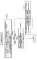
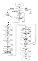
図1は、本発明の一実施形態に係る情報処理装置のハードウエア構成を示すブロック図である。
【0011】
この図1において、21は中央処理装置(CPU)であり、本装置の全体の制御や演算処理を行なう。また、11は、文字や数値の入力を行なうためのキーボードであり、12は、座標や図形を指示するためのマウスである。また、41は表示装置であり、図形データおよび文字データ、各種操作パネルやボタンを表示する。
【0012】
また、31は読出専用記憶装置(ROM)であり、本実施形態に係るプログラムは、このROM31に格納され、CPU21によって実行される。32は読出書込記憶装置(RAM)であり、本実施形態に係るプログラムの実行中、CPU21は、必要に応じて、RAM32に、データを読み書きしながら処理を行なう。33は、フロッピーディスク装置(FD)やハードディスク装置(HD)などの外部記憶装置であり、文字の書体情報やコード情報などのデータが格納されている。
【0013】
なお、本実施形態に係るプログラムを、外部記憶装置33に格納させておき、RAM32に読み込んでから、CPU21によって実行するようにしてもよいし、また、文字の書体情報やコード情報などのデータを、ROM31に格納させておき、CPU21が、必要に応じて、それらのデータを読み出して使用するようにしてもよい。
【0014】
また、51はレーザープリンタであり、本装置によって作成された印刷データを、校正刷り(印刷データの確認のための出力)し、また、印刷ログファイルの内容を出力する。52はイメージセッターであり、本装置によって作成された印刷データを、清刷り(正式な版下となる高精度な出力)する。53はレーザーマーカーであり、本装置によって作成された印刷データを、レーザーで直接、製品に焼き付ける。
【0015】
以下、レーザープリンタ51と、イメージセッター52と、レーザーマーカー53の違いについて説明する。
【0016】
まず、レーザープリンタ51は、レーザーを感光ドラムに照射してトナーを吸着させ、それを紙に転写するプリンタであり、解像度は、1500DPI程度まで可能である。また、イメージセッター52は、レーザーを直接、感光紙に照射するプリンタであり、解像度は、4000DPI程度まで可能であり、また、用紙サイズは、A1程度まで可能である。また、レーザーマーカー53は、レーザーを直接、成形品に照射し、樹脂材料を溶融して黒化させるか、充填材を配合した特殊材料を使用して発色させる印刷装置である。
【0017】
なお、22はシステムバスであり、本装置を構成するハードウエアの各要素は、全て、このシステムバス22を介して、プログラムおよびデータの受け渡しを行なっている。
【0018】
次に、本実施形態に係る表示装置41における表示機能について説明する。
【0019】
本実施形態に係る情報処理装置は、図形データおよび文字データを、印刷時の出力形態と同じ表示形態のイメージで、表示装置41へ表示する制御を行なう、いわゆるWYSIWYGの機能を有しており、これを説明する図が、図2である。
【0020】
図2(a)は、WYSIWYGの表示例であり、この図2(a)の表示形態は、印刷時の出力結果の例である図2(c)の出力形態と同じとなっている。一方、図2(b)は、WYSIWYGではない表示の例であり、この図2(b)の表示形態は、印刷時の出力結果の例である図2(c)の出力形態とは異なっている。
【0021】
次に、本実施形態に係る表示装置41上の操作画面について説明する。
【0022】
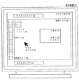
図3は、本実施形態に係るプログラム実行時に表示装置41に表示されるメインパネル61を示した図である。
【0023】
この図3において、61はメインパネル、62は作画エリア、63はマウスポインタ、64は文字入力エリア、65はボタン群、66は汎用ボタン、67はコマンドメニュー、68はガイダンスエリア、71はメインパネル以外のパネル、72はパネル71上のボタンである。また、これら図3上のボタンは、全てソフトキーである。
【0024】
このメインパネル61上で、キーボード11や、マウス12などの入力装置を操作することによって、対話的に、印刷データの作成および編集作業を行なう。作成された印刷データは、作画エリア62に表示される。
【0025】
また、必要に応じて、メインパネル61以外に、各種のパネル71が表示され、パネル71上で、操作を行なうこともある。
【0026】
以下、この図3を用いて、本実施形態における、さまざまな入力方法について説明する。
【0027】
キーボード11から入力を行なう場合には、文字入力エリア64を、マウス12またはキーボード11で指示してから、文字または数値を入力する。
【0028】
また、マウス12から入力を行なう場合には、以下の方法を用いる。
【0029】
まず、特定の要素やボタンを選択する方法としては、次の(1)と(2)の、2つの方法がある。
【0030】
(1)要素選択:作画エリア62に表示されている、印刷データのある場所に、マウスポインタ63を移動させて、その位置で、例えばマウス左ボタンを押し下げることによって、操作の対象とする要素を選択する。
【0031】
(2)ボタン選択:メインパネル61に表示されている、各種のボタン65や汎用ボタン66や、必要に応じて表示されるパネル71に表示されている、各種のボタン72の位置に、マウスポインタ63を移動させて、その位置で、例えばマウス左ボタンを押し下げることによって、操作の対象とするボタンを選択する。
【0032】
また、作画エリア62上の特定の位置を指定する方法として、次の(3)から(7)までの、5つの方法がある。
【0033】
(3)任意指定:作画エリア62上の、任意の位置に、マウスポインタ63を移動させて、その位置で、例えばマウス右ボタンを押し下げることによって、位置を指定する。
【0034】
(4)点指定:作画エリア62に表示されている、点を要素選択することによって、位置を指定する。
【0035】
(5)特徴点指定:作画エリア62に表示されている、点以外の要素を要素選択することによって、その要素の特徴となる点をCPU21が抽出し、位置を指定する。
【0036】
ここで、特徴点が複数存在する場合に、1点を特定する方法には、要素選択した際のマウスポインタ63の位置に最も近い特徴点をCPU21が自動的に抽出する方法、複数存在する特徴点の中からさらに1点を点指定する方法、などがある。
【0037】
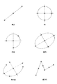
図4に、図形データの各要素の特徴点の例を示す。図中、*印で示した点が、特徴点である。なお、これら特徴点の具体的な位置は、以下に示す通りである。・線分:両端点、中点
・円:中心点、円の中心からXおよびY軸方向に引いた直線と円との交点(4点)
・円弧:中心点、両端点、中点(円弧の距離を二分する円弧上の点)
・楕円:中心点、楕円の短軸および長軸と楕円との交点(4点)
・楕円弧:中心点、両端点、楕円弧の短軸および長軸と楕円弧を含む楕円との交点(4点)、中点(楕円弧の距離を二分する楕円弧上の点)
・線分列:線分列を構成する各線分の両端点、中点
・自由曲線:両端点、曲線の制御点、中点(自由曲線の距離を二分する点)。
【0038】
(6)交点指定:作画エリア62に表示されている、線分や円などの線要素を、1個または2個、要素選択することによって、それらの要素の交点をCPU21が算出し、位置を指定する。
【0039】
ここで、単一の線要素が、それ自体で交点を持つ場合、すなわち、自己交差している場合は、線要素を1個、要素選択するだけでよい。その他の場合は、2個の線要素を指定する。
【0040】
交点が複数存在する場合に、1点を特定する方法には、先または後に要素選択した際のマウスポインタ63の位置に最も近い交点をCPU21が自動的に抽出する方法、複数存在する交点の中からさらに1点を点指定する方法、などがある。
【0041】
図5に、線分と円弧を要素選択して、交点指定によって、位置を指定した例を示す。図中、レ印で示した位置で、線分、円弧、の順で、要素選択を行ない、*印の位置が、交点指定によって指定されたことを示している。
【0042】
(7)線上点指定:作画エリア62に表示されている、線分、円などの、線要素を1個、要素選択することによって、その時のマウスポインタ63の位置に最も近い、線要素上の点をCPU21が算出し、位置を指定する。
【0043】
図6に、円弧を要素選択して、線上点指定によって、位置を指定した例を示す。図中、レ印で示した位置で、要素選択を行ない、*印の位置が、線上点指定によって指定されたことを示している。レ印の点は、円弧近傍の点、*印の点は、円弧上の点である。
【0044】
次に、本実施形態で扱う「コマンド」について説明する。本実施形態では、印刷データの作成および編集作業の各単位を「コマンド」と呼んでいる。
【0045】
本実施形態で扱うコマンドには、点、直線、円、曲線、など、各要素を作成するコマンド(作図コマンド)や、移動、複写、削除、属性、など、各要素の形状や属性などを修正するコマンド(修正コマンド)や、その他、ファイル、プリント、トンボ、バーコード、等に関するコマンドなどがある。
【0046】
印刷データの作成や編集を行なうには、まず、作業単位に合わせた、任意のコマンドを1つ選択する。コマンドの選択には、文字入力エリア64で、コマンドの名称をキーボード11から入力する方法や、コマンドの名称があらかじめ設定されているメインパネル61上のボタン65を、ボタン選択する方法などがある。
【0047】
コマンドの選択が行なわれると、それまで、すでに選択されているコマンドがあった場合には、そのコマンドの終了処理が行なわれる。続いて、新たに選択されたコマンドの初期処理が行なわれ、コマンド内の処理に入る。
【0048】
コマンドが選択されると、表示装置41上に、選択されたコマンド内での、さらに細かい作業単位を選択するための、コマンドメニュー67が表示される。ユーザーは、コマンドメニュー67の任意のメニュー項目のボタンをボタン選択することによって、各種の編集作業を行なうことができる。ユーザーがどのような操作を行なえばよいかといった指示は、作業の状況に応じて、その都度、ガイダンスエリア68に表示されるので、ユーザーは、この指示に従って、操作を行なえばよい。
【0049】
[印刷データの説明]
○印刷データの要素
次に、本実施形態に係る情報処理装置で作成できる印刷データを構成する、図形データおよび文字データの要素に、どのような種類が存在するのかを、具体的に説明することにする。
【0050】
本実施形態に係る情報処理装置で作成できる、図形データおよび文字データの要素には、大きく分けて、以下の(A)〜(E)の5つの種類がある。
(A)基本図形:点、線分、線分列(開/閉)、円、円弧、楕円、楕円弧、自由曲線(開/閉)
(B)塗り潰し図形
(C)その他の図形:トンボ、バーコード
(D)テキスト
(E)グループ図形:シンボル、イラスト。
【0051】
ここでいう要素とは、図形データまたは文字データに、印刷データとして必要な属性(印刷属性と呼ぶ)を付加して、実際に、印刷データとしてレイアウトされる、データの単位を意味している。また、印刷データとしてレイアウトされた複数の要素をまとめてグループ化すれば、それを1つの要素として扱うこともできる。要素のグループ化の方法については、後述する。
それでは、以上の(A)〜(E)の5つの種別について、以下に詳細に説明することにする。
【0052】
まず、(A)の基本図形は、最も基本となる図形データの要素である。このほか、線分列によって構成される、矩形(各辺がXおよびY軸に平行である長方形)、正多角形などを、基本図形の要素として扱うこともできる。また、自由曲線としては、ベジェ、有理ベジェ、Bスプライン、エルミート、NURBSなどの表現形式を扱うことができる。
【0053】
また、(B)の塗り潰し図形は、(A)の要素(点を除く)を単独で、または、複数を連結させることで、閉領域を形成し、その内部を塗り潰した図形データの要素である。塗り潰しの方法には、次の4種類がある。
(1)フィルエリア:内部を均一に塗り潰す。
(2)ハッチング:一定の傾きと間隔を持った複数の線分で塗り潰す。塗り潰し図形内の特定の点を、ハッチングの基準点として指定することもできる。
(3)メッシュ:円、矩形、正多角形など、一定の形状の図形の繰り返しで塗り潰す。塗り潰し図形内の特定の点を、メッシュの基準点として指定することもできる。
(4)パターン:あらかじめ作成されたビットパターンの繰り返しで塗り潰す。
【0054】
また、(C)のその他の図形には、トンボ、バーコードなどがある。これらの要素は、図形データと、文字データの両方を含んでいる。トンボ、バーコードの各要素の作成方法については、後述する。
【0055】
また、(D)のテキストは、文字データの要素である。図形データの要素と同様に、印刷データとしてレイアウトすることができるが、印刷属性の種類や、レイアウトの方法は、図形データの要素とは異なる。
【0056】
最後に、(E)のグループ図形は、(A)の基本図形、(B)の塗り潰し図形、(C)のその他の図形、(D)のテキストの各要素を、1つ以上任意の数だけ選択して、まとめて1つの要素として扱うためのもので、シンボルとイラストがある。
【0057】
○印刷データの印刷属性
次に、本実施形態に係る情報処理装置で作成できる印刷データである、図形データおよび文字データの印刷属性に、どのような種類が存在するのかを、具体的に説明することにする。
【0058】
本実施形態に係る情報処理装置で作成できる、図形データおよび文字データの印刷属性には、大きく分けて、以下の(a)〜(g)の7つの種類がある。
【0059】
まず、図形データおよび文字データに共通の印刷属性には、次に示す(a)〜(c)の3つの種類がある。
(a)表示属性:要素を表示するか否か、また、表示する場合に、どのような上下関係で表示するか(表示プライオリティと呼ぶ)を指定する。
(b)選択属性:要素選択が可能であるか否かを指定する。要素選択を不可にすると、その要素に対しての操作は行なえなくなる。
(c)色属性:RGBあるいはHLSなどのカラーモデルの種別、および、カラーコードの値を与えることによって、要素の色を表現する。白と黒以外の色が表現できないモノクロームの、表示装置41またはレーザープリンタ51などの印刷装置を使用している場合、色属性に応じて、白または黒のどちらかの色に変換されて、出力される。
【0060】
次に、図形データ固有の印刷属性には、次に示す(d)〜(f)の3つの種類がある。
(d)点属性:点要素の場合、点のある位置に記号を表示したり、文字列を表示したりすることができる。
(e)線属性:点以外の基本図形の要素(線要素)の場合、次に示す、さまざまな線の属性を表現することができる。
・線種:線要素の形状を示し、実線、破線、一点鎖線、二点鎖線、などがある。・線幅:線要素の法線方向の大きさを示す。あらかじめ定められた、細線、中線、太線、などの種別を指定したり、実寸で指定したりすることができる。
・線幅方向:線幅を考慮しない場合から、法線方向のどちらに線幅分だけオフセットさせるかを示す。
・終端形状:線分や円弧などの開図形の終端の形状で、ラウンド、フラット、スクエア、などがある。
・接続形状:線分列や矩形などの図形の角の形状で、マイター、ラウンド、ベベル、などがある。
・線ピッチ:線種が実線以外の場合、線が存在する部分と、存在しない部分の長さを、それぞれ、実寸またはパラメータで与えることができる。
(f)塗り潰し属性:塗り潰し図形要素の場合、フィルエリア、ハッチング、メッシュ、パターン、などの内部の塗り潰し方法の種類や、ハッチングやメッシュの場合の、必要な詳細データ、パターンの場合の、パターン番号を与える。
【0061】
最後に、文字データ固有の印刷属性には、次に示す(g)の1種類のみがある。
(g)文字列属性:テキスト要素の場合、次に示す、さまざまな、文字の属性、および文字列全体の属性を表現することができる。
・書体:一組の文字のデザインを表し、クーリエ、ヘルベチカ、ゴシック、などがある。
・文字サイズ:文字の大きさを表し、一般には1つの文字が専有する矩形領域=ボディ(文字ボックスと表現する場合もある)、の行送り方向の高さと等しい。
・平体率:文字を、文字の行送り方向にどれだけ縮めるかを比率で表す。
・長体率:文字を、文字の字送り方向にどれだけ縮めるかを比率で表す。
・ベース角:文字の字送り方向がX軸となす角度を表す。
・斜体角:文字の字送り方向に対する、文字の傾斜角度を表す。
・字間:同一行の隣接する2文字のボディの間隔を表す。
・行間:隣接する2行にある文字のボディの間隔を表す。
・文字列反転:文字列を反転(鏡像)して表示する。
【0062】
○印刷データのデータ構造
次に、本実施形態における印刷データのデータ構造について説明する。本実施形態における印刷データは、一般に、既に説明したような、複数の要素データ、複数の印刷属性データから構成されている。
【0063】
ここで、各要素データは、基本的に、データ種別コード、データ番号、各要素ごとの必要データ、各要素ごとの必要印刷属性データのデータ番号、という構成になっている。
【0064】
そして、印刷データ内でユニークに付けられたデータ種別コードによって、印刷データ内の各要素データの種別を特定することができる。また、印刷データ内でユニークに付けられたデータ番号によって、印刷データ内の各要素データを特定することができる。各要素ごとに、必要データ、必要印刷属性の種類は異なるが、データ種別コードによって、CPU21は、これらを識別することが可能である。
【0065】
また、各印刷属性については、各要素データごとに保持するのではなく、各要素データでは、必要な印刷属性データのデータ番号のみを保持するようにしている。これによって、印刷属性データの重複を避け、印刷データの容量を縮小することや、複数の要素データの印刷属性を一度の操作で変更することなどが可能になっている。
【0066】
それでは、まず、図形データおよび文字データの各要素のデータ構造を、以下に具体的に示すことにする。
【0067】
(A)基本図形
(1)点
・データ種別コード
・データ番号
・点座標:c[2]
・表示属性のデータ番号
・選択属性のデータ番号
・色属性のデータ番号
・点属性のデータ番号
(2)線分
・データ種別コード
・データ番号
・始点座標:s[2]
・終点座標:e[2]
・表示属性のデータ番号
・選択属性のデータ番号
・色属性のデータ番号
・線属性のデータ番号
(3)線分列
・データ種別コード
・データ番号
・通過点数:np
・各通過点座標:pp[2](np個)
・表示属性のデータ番号
・選択属性のデータ番号
・色属性のデータ番号
・線属性のデータ番号
(4)円
・データ種別コード
・データ番号
・中心座標:c[2]
・半径:r
・表示属性のデータ番号
・選択属性のデータ番号
・色属性のデータ番号
・線属性のデータ番号
(5)円弧
・データ種別コード
・データ番号
・始点座標:s[2]
・終点座標:e[2]
・中心座標:c[2]
・回り方向フラグ(時計回り/反時計回り)
・表示属性のデータ番号
・選択属性のデータ番号
・色属性のデータ番号
・線属性のデータ番号
(6)楕円
・データ種別コード
・データ番号
・中心座標:c[2]
・長軸ベクトル:a[2]
・短軸ベクトル:b[2]
・表示属性のデータ番号
・選択属性のデータ番号
・色属性のデータ番号
・線属性のデータ番号
(7)楕円弧
・データ種別コード
・データ番号
・始点座標:s[2]
・終点座標:e[2]
・中心座標:c[2]
・長軸ベクトル:a[2]
・短軸ベクトル:b[2]
・回り方向フラグ(時計回り/反時計回り)
・表示属性のデータ番号
・選択属性のデータ番号
・色属性のデータ番号
・線属性のデータ番号
(8)自由曲線(ベジェ曲線の場合)
・データ種別コード
・データ番号
・曲線数:nv
・各曲線の制御点データ(nv個):
制御点数:nc
各制御点座標:pc[2](nc個)
重み係数:w
・通過点数:np
・各通過点座標:pp[2](np個)
・表示属性のデータ番号
・選択属性のデータ番号
・色属性のデータ番号
・線属性のデータ番号。
【0068】
(B)塗り潰し図形
・データ種別コード
・データ番号
・レイアウト基準矩形左下点座標:p1[2]
・レイアウト基準矩形右上点座標:p2[2]
・ループ数:nl
・各ループの構成要素データ(nl個):
構成要素数:nd
構成要素データ:点を除く基本図形要素データ(nd個)
・通過基準点座標:pp[2]
・表示属性のデータ番号
・選択属性のデータ番号
・色属性のデータ番号
・塗り潰し属性のデータ番号
・枠の表示属性のデータ番号
・枠の色属性のデータ番号
・枠の線属性のデータ番号
(塗り潰し図形では、印刷属性として、塗り潰し図形の内部の印刷属性の他に、塗り潰し図形の枠の印刷属性を別に持っている。例えば、内部の色属性と、枠の色属性を変えて表示することなどが可能である)。
【0069】
(C)その他の図形
(1)トンボ
・データ種別コード
・データ番号
・トンボ種別フラグ(トンボ/スケールトンボ)
・トンボ形状フラグ(トンボの場合は11種類/スケールトンボの場合は3種類)
・トンボオフセットフラグ(オフセットあり/なし)
・印刷データ名称(スケールトンボの場合)
・トンボ長さ(スケールトンボの場合)
・レイアウト基準点座標:pb[2]
・出力倍率:sc
・レイアウト基準矩形左下点座標:p1[2]
・レイアウト基準矩形右上点座標:p2[2]
・構成要素数:nd
・構成要素データ:トンボの場合は線分、スケールトンボの場合は線分、円、テキストのいずれかの要素データ(nd個)
(2)バーコード
・データ種別コード
・データ番号
・バーコード種別フラグ(4種類)
・コードデータ
・コード表示フラグ(コード表示あり/なし)
・レイアウト基準位置フラグ(左下/中央/右上など9種類)
・レイアウト基準点座標:pb[2]
・レイアウト角度:ang
・レイアウトスケール:sc
・レイアウト基準矩形左下点座標:p1[2]
・レイアウト基準矩形右上点座標:p2[2]
・構成要素数:nd
・構成要素データ:線分、テキストのいずれかの要素データ(nd個)。
【0070】
(D)テキスト
(1)基本文字列(テキストを構成する要素)
・データ種別コード
・データ番号
・文字列開始点座標:pt[2]
・文字列バイト数:nch
・文字列データ:str(nchバイト)
・レイアウト角度:ang
・レイアウトスケール:sc
・表示属性のデータ番号
・選択属性のデータ番号
・色属性のデータ番号
・文字列属性のデータ番号
(2)テキスト
・データ種別コード
・データ番号
・レイアウト基準位置フラグ(左下/中央/右上など9種類)
・レイアウト基準点座標:pb[2]
・レイアウト基準矩形左下点座標:p1[2]
・レイアウト基準矩形右上点座標:p2[2]
・構成要素数:nd
・構成要素データ:基本文字列の要素データ(nd個)
(テキスト要素は、複数の基本文字列要素を組み合わせて構成される。これによって、ひとつのテキスト要素の中で、複数の文字列属性を持った文字列を扱うことが可能となる。例えば、ひとつのテキストの途中で文字の書体を変更したり、文字の高さや幅を変更したり、といった制御が可能である)。
【0071】
(E)グループ図形
(1)シンボル
・データ種別コード
・データ番号
・フォルダー名称
・ファイル名称
・レイアウト基準位置フラグ(左下/中央/右上など9種類)
・レイアウト基準点座標:pb[2]
・レイアウト角度:ang
・レイアウトスケール:sc
・レイアウト基準矩形左下点座標:p1[2]
・レイアウト基準矩形右上点座標:p2[2]
・反転フラグ(反転あり/なし)
・線幅スケールフラグ(線幅スケールあり/なし)
・線幅スケール値
(2)イラスト
・データ種別コード
・データ番号
・フォルダー名称
・ファイル名称
・レイアウト基準位置フラグ(左下/中央/右上など9種類)
・レイアウト基準点座標:pb[2]
・レイアウト角度:ang
・レイアウトスケール:sc
・レイアウト基準矩形左下点座標:p1[2]
・レイアウト基準矩形右上点座標:p2[2]
・反転フラグ(反転あり/なし)
・構成要素数:nd
・構成要素データ:任意の要素データ(nd個)
(シンボルおよびイラストのデータ構造の特徴、およびシンボルデータファイルおよびイラストデータファイルのファイル構造については、後述する)。
【0072】
次に、上述したようなデータ構造を有する要素データに対する印刷属性データのデータ構造について説明する。
【0073】
ここで、各印刷属性データは、基本的に、データ種別コード、データ番号、属性設定フラグ、各印刷属性ごとの必要データ、という構成になっている。
【0074】
印刷データ内でユニークに付けられたデータ種別コードによって、印刷データ内の各印刷属性データの種別を特定することができる。また、印刷データ内でユニークに付けられたデータ番号によって、印刷データ内の各印刷属性データを特定することができる。各印刷属性ごとに、必要データは異なるが、データ種別コードによって、CPU21は、これらを識別することが可能である。
【0075】
また、属性設定フラグとは、その印刷属性データが有効であるか否かを指定するフラグである。属性設定フラグが有効である印刷属性データを指示している要素データでは、該当する印刷属性データに従って、要素が表示される。一方、属性設定フラグが無効である印刷属性データを指示している要素データでは、該当する印刷属性は設定されていない状態であると見なし、あらかじめROM31や外部記憶装置33に記憶されているデフォルトの印刷属性に従って、要素が表示される。
【0076】
また、各要素データに階層関係を持たせることが可能なデータ構造とした場合には、上位の(または下位の)要素の印刷属性に従って表示を行なったりする制御も可能である。
【0077】
それでは、各印刷属性データのデータ構造を、以下に具体的に示すことにする。
(a)表示属性
・データ種別コード
・データ番号
・属性設定フラグ(有効/無効)
・表示フラグ(表示/非表示)
・表示プライオリティ
(b)選択属性
・データ種別コード
・データ番号
・属性設定フラグ(有効/無効)
・要素選択フラグ(可/不可)
(c)色属性
・データ種別コード
・データ番号
・属性設定フラグ(有効/無効)
・カラーコード種別フラグ(RGB/HLS)
・カラーコード1、2、3
(d)点属性
・データ種別コード
・データ番号
・属性設定フラグ(有効/無効)
・マーカー文字列
(e)線属性
・データ種別コード
・データ番号
・属性設定フラグ(有効/無効)
・線種フラグ(実線/破線/一点鎖線/二点鎖線/任意破線/任意一点鎖線/任意二点鎖線)
・線幅フラグ(細線/中線/太線/極太線/任意線幅)
・線幅方向フラグ(中央/内側/外側)
・終端形状フラグ(ラウンド/フラット/スクエア)
・接続形状フラグ(マイター/ラウンド/ベベル)
・線種データ1、2、3、4(線種=任意のとき)
・線幅データ(線幅=任意のとき)
(f)塗り潰し属性
・データ種別コード
・データ番号
・属性設定フラグ(有効/無効)
・塗り潰し種別フラグ(塗り潰しあり/塗り潰しなし/ハッチング/メッシュ番号/パターン番号など)
・データグループ数:nd
・塗り潰しデータ1、2、3(nd個)
(g)文字列属性
・データ種別コード
・データ番号
・属性設定フラグ(有効/無効)
・書体
・文字サイズ
・平体率
・長体率
・ベース角
・斜体角
・字間
・行間
・文字列反転フラグ(あり/なし)。
【0078】
図7に、以上示した印刷データのデータ構造に基いて、本実施形態に係る情報処理装置で作成された、印刷データファイルの一例を示す。
この図7に示された印刷データは、図8に示すような形状の図形を印刷するためのものであり、本実施形態においては、図7に示す印刷データにより表現される図形が、基本図形の要素から成り、1個の線分列と2個の円と、これら3要素の外接矩形の左下点および右上点の2点(この2点は非表示で選択不可)から構成されるものとし、また、これら1個の線分列と2個の円が、それぞれ同じ表示属性(表示)、選択属性(選択可)、線属性(実線、線幅20mm)を持ち、互いに異なる色属性を持っているものとする。
【0079】
○グループ図形のデータ構造
それでは、上述した印刷データのデータ構造のうち、特に、グループ図形であるシンボルとイラストのデータ構造について、詳しく説明することにする。
【0080】
まず、シンボルのデータ構造について説明する。
【0081】
本実施形態において、シンボルとは、規格で定められた記号や、ロゴマークのように、繰り返し使用される図形で、図形データの要素(線分や円など)や、文字データの要素(テキスト)を組み合わせて、作成される要素である。
【0082】
シンボルデータの場合、規格が変更されるなどして、シンボルデータファイルの内容が更新された場合には、既に印刷データの一部としてレイアウト済みである、該当するシンボルを、全て更新してデータの同期を維持できるようになっている。
【0083】
そこで、本実施形態に係る情報処理装置では、シンボルのデータを、次に示すようなデータ構造で保持している。
【0084】
すなわち、印刷データ内には、シンボルデータファイルの存在場所を特定するための、フォルダー名称およびファイル名称、そして、シンボルをレイアウトするために必要な情報のみを保持する。
【0085】
また、印刷データをファイルに保存した印刷データファイルとは別個に、シンボルデータファイルを作成する。シンボルデータファイルは、次に示すようなファイル構造となっている。
・レイアウト基準矩形左下点座標:p1[2]
・レイアウト基準矩形右上点座標:p2[2]
・構成要素データ:任意の要素データ(複数)
・印刷属性データ:必要な印刷属性データ(複数)。
【0086】
レイアウト基準矩形については後述するが、レイアウト基準矩形を定めておけば、シンボルを印刷データとしてレイアウトする際に必要な、位置と大きさの情報を特定することが可能である。例えば、レイアウト基準矩形としては、シンボルの可視部分を囲む最小の矩形(外接矩形と呼ぶ)を指定しておくことなどが可能である。
【0087】
シンボルデータファイルを作成する際に、該当するシンボルの外接矩形のデータをレイアウト基準矩形として登録しておけば、シンボルデータファイルを再度、読み込んだ際などに、シンボルの外接矩形を再計算する必要がなくなる。
【0088】
シンボルの各構成要素データは、レイアウト基準矩形左下点を基準とする相対座標値で、表現されている。
【0089】
また、各印刷属性データについては、印刷データの場合と同様に、各構成要素データを表示する際に必要な印刷属性データを、要素データとは別に保持している。
【0090】
これによって、変更のあったシンボルを含む印刷データファイルの更新を行なわなくても、該当する印刷データファイルを、外部記憶装置33から、RAM32に再度、読み込んで来るだけで、印刷データ内のシンボルデータは最新のシンボルデータファイルの内容に置き換わり、データの同期が自動的に取れるようになっている。
【0091】
次に、もう一つのグループ図形であるイラストのデータ構造について説明する。
【0092】
本実施形態において、イラストとは、テンプレート図形のように、繰り返し使用される図形で、これもまた、シンボルと同様に、図形データの要素(線分や円など)や、文字データの要素(テキスト)を組み合わせて、作成される要素である。
【0093】
イラストは、シンボルとは異なり、いったん、印刷データの一部として、レイアウトされた後は、元のイラストデータファイルの内容とは、同期を取らずに、自由に変更を加えたい場合に使用される。
【0094】
従って、イラストデータの場合、シンボルデータとは異なり、イラストデータファイルの内容が更新された場合でも、既に印刷データの一部としてレイアウト済みである、該当するイラストを、更新して同期を維持することはない。
【0095】
そこで、本実施形態に係る情報処理装置では、イラストのデータを、次に示すようなデータ構造で保持している。
【0096】
すなわち、印刷データ内には、イラストデータファイルの存在場所を特定するための、フォルダー名称およびファイル名称、そして、イラストをレイアウトするために必要な情報、の他に、イラストデータファイルから読み込んだ、実際にイラストを構成する各要素データを保持している。
【0097】
また、印刷データファイルとは別個に、イラストデータファイルを作成する。イラストデータファイルは、次に示すようなファイル構造となっている。
・レイアウト基準矩形左下点座標:p1[2]
・レイアウト基準矩形右上点座標:p2[2]
・構成要素データ:任意の要素データ(複数)
・印刷属性データ:必要な印刷属性データ(複数)。
【0098】
この構造は、シンボルデータファイルのファイル構造と同様である。これを印刷データに読み込む際には、指定したレイアウト基準点座標を原点とし、指定したレイアウト角度、レイアウトスケールに従って、イラストデータファイル内の各構成要素データを展開して(座標変換して)、印刷データのイラスト要素データとして、全て保持する点が、シンボルとは異なっている。
【0099】
[印刷データの作成]
それでは、具体的に印刷データを作成する手順を、図形データ、文字データ、トンボ、バーコード、の4つの場合に分けて、詳細に説明する。本実施形態においては、図形データの例として、シンボルを作成する場合を説明し、また、文字データの例として、テキストを作成する場合を説明する。
【0100】
○シンボルの作成
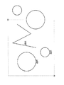
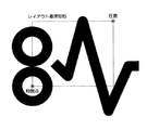
まず、図形データを作成する例として、図8に示すようなシンボルを作成する場合について説明する。
【0101】
この図8に示すシンボルは、2個の円要素、1個の線分列要素、といった基本図形から構成されている。ここでは、
(A)基本図形を印刷データとしてレイアウトする
(B)シンボルの構成要素をグループ化し、シンボルとして登録する
(C)登録されたシンボルを呼び出して、印刷データとしてレイアウトする
という、3つのフローに分けて説明する。
【0102】
まず、基本図形を印刷データとしてレイアウトする処理について説明する。
【0103】
(A)基本図形のレイアウト
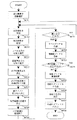
図9に、基本図形を印刷データとしてレイアウトする手順を説明するフローチャートを示す。
【0104】
まず、基本図形を作成するために必要な、座標値や半径などの、必要情報を入力する(ステップS0901)。この必要情報の入力処理については、後で詳しく説明する。
【0105】
次に、図形データに印刷属性を付加して、印刷データとして使用できるようにする(ステップS0902)。この印刷属性の付加処理については、後で詳しく説明する。
【0106】
そして、ステップS0902で印刷属性が付加されると、次に、CPU21は、作成された基本図形要素のデータを、印刷データとして、RAM32に登録する(ステップS0903)。そして、さらに、CPU21は、作成された基本図形要素を、作画エリア62に表示する(ステップS0904)。
【0107】
以下、ステップS0901における必要情報の入力処理について説明する。
【0108】
これは、基本図形の種類によって異なった操作となる。
【0109】
例えば、円を作成する場合には、次のような操作となる。
(1)円の中心の位置を、マウス12で既に存在する点を要素選択、または任意指定したり、キーボード11でXおよびYの座標値を入力することによって指定する。
(2)円周上の1点の位置を、マウス12で既に存在する点を要素選択、または任意指定したり、キーボード11でXおよびYの座標値を入力することによって、指定する。または、キーボード11で半径を入力する。
【0110】
中心と円周上の1点、または、中心と半径を指定する上記の方法以外にも、円周上の異なる3点を指定する方法、円周上の異なる2点と半径を指定する方法、などがある。
【0111】
また、これらの操作手順は、ガイダンスエリア68に表示されるので、ユーザーは、この指示に従って、操作を行なえばよい。
【0112】
線分列を作成する場合には、次のような操作となる。
(1)線分列の始点の位置を、マウス12で既に存在する点を要素選択、または任意指定したり、キーボード11でXおよびYの座標値を入力することによって、指定する。
(2)同様にして、通過点をいくつでも指定する。
(3)汎用ボタン66を、ボタン選択することなどによって、通過点の指定の終了を指示する。
【0113】
次に、以下、ステップS0902における印刷属性の付加処理について説明する。
【0114】
まず、図形データの印刷属性の種類については、前述した通りである。
【0115】
例として、図10に、印刷属性の付加されていない状態の図形データと、付加されている状態の図形データを示す。印刷属性が付加されていない状態では、線幅、終端形状、接続形状、などの違いが表現できていないことがわかる。印刷属性が付加されていない状態とは、前述した印刷属性データの構造の中で、属性設定フラグが無効となっている場合である。なお、属性設定フラグが無効となっている場合でも、図形データの形状は、所定の印刷属性で出力される。
【0116】
刷属性を、図形データの要素に付加するには、表示装置41に表示される専用のパネルが必要である。
【0117】
図11に、そのような図形データの要素を付加するために使用する、図形データ印刷属性編集パネル1101を示す。ユーザーは、この図形データ印刷属性編集パネル1101で、印刷属性を編集することができる。
【0118】
図形データ印刷属性編集パネル1101が表示された状態で、線種として、実線以外の種別を選択し、さらに、図形データ印刷属性編集パネル1101の、「線ピッチ」ボタンを、ボタン選択すると、図12に示すような、破線、一点鎖線、二点鎖線のそれぞれの種別に応じた、線ピッチ編集パネル1201が表示される。そして、この線ピッチ編集パネル1201上で、線ピッチデータを編集することが可能となる。図12に示したのは、二点鎖線の場合の表示例である。
【0119】
印刷属性を編集するには、図形データ印刷属性編集パネル1101上で、編集したい印刷属性の文字入力エリアを、マウス12またはキーボード11で指示し、キーボード11で、数値データを入力するか、または、選択する項目のボタンを、ボタン選択してから、「設定」ボタンを、ボタン選択すればよい。
【0120】
これから作成しようとする印刷データに対して、印刷属性の設定を行なう場合には、図形データ印刷属性編集パネル1101上で、上記の方法で各印刷属性の入力を行なってから、図形データの各要素を作成すればよい。
【0121】
また、いったん、印刷属性を設定しておけば、CPU21はこれらを、カレントな印刷属性として、RAM32に保存しておくので、要素を作成するたびに、印刷属性を設定する必要はない。
【0122】
また、プログラムを終了する際に、CPU21は、カレントな印刷属性を、外部記憶装置33に保存し、次に、プログラムを実行する際に、再び、RAM32に、読み込んで来るので、プログラムを実行するたびに、カレントな印刷属性を設定し直す必要もない。カレントな印刷属性は、ユーザーによらず共通のものと、ユーザーが各自設定した個別のものを、別々に、RAM32や外部記憶装置33に、保存しておくこともできる。
【0123】
すでに作成された印刷データに対して、印刷属性の編集を行なう場合には、作画エリア62に表示されている要素を要素選択すれば、CPU21が、図形データか文字データかを判断して、図形データの場合は、図形データ印刷属性編集パネル1101を、表示装置41に表示する。
【0124】
この際、要素選択された要素の現在の印刷属性が、図形データ印刷属性編集パネル1101に表示されるので、上記の方法で印刷属性を編集してから、「設定」ボタンを、ボタン選択すればよい。作画エリア62上の対象要素は、編集された新しい印刷属性に従って、再描画される。
【0125】
以上、基本図形を印刷データとしてレイアウトする手順を説明した。
【0126】
次に、シンボルの構成要素をグループ化し、シンボルとして登録する処理について説明する。
【0127】
(B)要素のグループ化とシンボルの登録
図13に、シンボルの構成要素をグループ化し、シンボルとして登録する手順を説明するフローチャートを示す。
【0128】
まず、シンボルとして登録したい対象要素をグループ化する(ステップS1301)。この対象要素のグループ化処理については、後で詳しく説明する。
【0129】
次に、ステップS1301でシンボルを構成する要素が特定されると、CPU21は、この各要素について、印刷属性を考慮して、輪郭情報を抽出する(ステップS1302)。この輪郭情報の抽出処理については、後で詳しく説明する。
【0130】
ステップS1302で、対象となる各要素の輪郭情報を抽出した後、CPU21は、抽出した輪郭情報から、外接矩形を計算する(ステップS1303)。
【0131】
ここでいう外接矩形とは、要素の可視部分を囲む最小サイズの矩形、のことであり、対角の2点のXおよびY座標を与えることによって特定される。
【0132】
このように、要素の外接矩形は、対角の2点によって特定できるので、抽出した輪郭情報から、最大のXおよびY座標、最小のXおよびY座標の値を算出し、外接矩形の左下点と右上点を、
左下点(輪郭情報の最小のX座標,輪郭情報の最小のY座標)
右上点(輪郭情報の最大のX座標,輪郭情報の最大のY座標)
と与えれば、外接矩形を容易に得ることができる。
【0133】
そして、ステップS1303で、グループ化された要素の外接矩形が求まると、CPU21は、作画エリア62に既に表示されているグループ化された要素に重ねて、その外接矩形を表示する(ステップS1304)。その表示は、例えば、図21のようになる。
【0134】
次に、グループ化された要素のレイアウト基準情報を定義するレイアウト基準矩形を設定する(ステップS1305)。このレイアウト基準矩形の設定処理については、後で詳しく説明する。
【0135】
そして、以上の一連の処理により、シンボルとして登録するための要素がグループ化され、そのレイアウト基準矩形が求まったので、そのシンボルを識別するキーとしてユーザーによりキーボード11等から入力された文字列を、シンボルの名称として決定する(ステップS1306)。
【0136】
最後に、CPU21は、先に図7で示したような構造を持つシンボルデータファイルとして、当該シンボルに関するデータを、外部記憶装置33に保存する(ステップS1307)。
【0137】
なお、このようにレイアウト基準矩形を設定した場合、図7に示すシンボルデータファイルの構造におけるレイアウト基準位置を明示的に指定しているわけではないが、シンボルデータファイルに保存する際には、レイアウト基準矩形の、例えば左下点を、常にレイアウト基準位置としておけばよい。
【0138】
また、シンボルを構成する各要素の座標データは、レイアウト基準位置からの相対座標で表現する。
【0139】
以下、ステップS1301における対象要素のグループ化処理について説明する。
【0140】
要素をグループ化するには、次のような方法がある。この方法は、要素をグループ化する場合に限らず、複数の要素をまとめて、複写、移動、削除などの処理を一括して行なう場合にも、使うことができる方法である。
【0141】
(1)連続要素選択:グループ化の対象とする要素を、1要素ずつ要素選択していく。要素選択を終了する際には、メインパネル61上の、汎用ボタン66を押すか、作画エリア62上で、マウスのどれかのボタンをダブルクリック(ボタンを短時間に2度押し下げる)する。
【0142】
(2)矩形領域指定:グループ化の対象とする要素が含まれる領域を、矩形で囲むことによって指定する。矩形を特定するためには、対角の2点の位置を、任意指定や点指定などの方法で指定すればよい。この場合、指定した矩形の内部に全体が含まれる要素を対象とする。
【0143】
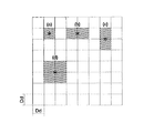
図14に、この方法によって、対象となる要素が選択された状態の一例を示す。
【0144】
この図14において、*印で示した位置を指定すると、作画エリア62に、領域を示す矩形が表示される。図中、「選択」と示されている要素が選択され、実際には、赤色などで表示されて、識別できるようになっている。
【0145】
なお、指定した矩形の内部に一部が含まれる要素を対象としたり、指定した矩形の内部に全く含まれない要素を対象としてもよい。
【0146】
(3)任意領域指定:グループ化の対象とする要素が含まれる領域を、多角形で囲むことによって指定する。多角形を構成する各点は、任意指定や点指定などの方法で指定すればよい。この場合、指定した多角形の内部に一部が含まれる要素を対象とする。
【0147】
図15に、この方法によって、対象となる要素が選択された状態の一例を示す。
【0148】
この図15において、*印で示した位置を指定すると、作画エリア62に、領域を示す多角形が表示される。図中、「選択」と示されている要素が選択され、実際には、赤色などで表示されて、識別できるようになっている。
【0149】
なお、指定した多角形の内部に全体が含まれる要素を対象としたり、指定した多角形の内部に全く含まれない要素を対象としてもよい。
【0150】
次に、ステップS1302における輪郭情報の抽出処理について説明する。
【0151】
図16は、図8に示すシンボルの輪郭情報を抽出した結果を示した図である。
【0152】
輪郭情報は、線分、円、円弧、楕円、楕円弧、自由曲線などの、線要素が連結したものとして表現できる。ただし、輪郭情報においては、線幅などの印刷属性は考慮する必要はなく、それ自体、領域を持たない図形であると見なす。
【0153】
印刷属性の付加された、図形データおよび文字データの輪郭情報を抽出する方法には、以下のものがある。
【0154】
(1)そのまま表示装置に表示する方法:
本実施形態に係る情報処理装置では、図2で示したように、WYSIWYGの機能が実現されているので、印刷属性の付加されたデータは、印刷時の出力形態と同じ表示形態のイメージで、表示装置41に表示される。
【0155】
例えば、このWYSIWYGの機能が、ディスプレイポストスクリプト(DPS)によって、実現されている場合には、図形データまたは文字データの、輪郭情報を抽出するための、ポストスクリプト(PS)の命令(オペレータ)を、表示されている、図形データまたは文字データに対して、発行してやればよい。
【0156】
これによって得られる輪郭情報の座標データは、表示装置41の画面上のドットの大きさが最小単位となる量子化されたデータである。そのため、この値は、一般に、誤差を含んでいる。
【0157】
表示装置41の1ドットの幅および高さをDd(インチ)とすると、図17に示すように、実際の座標が、(b)や(c)のように、2つのドットの境界や、(d)のように、4つのドットの角の位置に一致する場合を考慮すると、得られる座標データの誤差は、最大で、Dd*2(インチ)となる。
【0158】
図17の、*印で示した位置が、量子化されていない実際の座標位置、斜線で示した矩形が、その時の画面上のドット、すなわち、量子化された値を示している。
【0159】
表示装置41の解像度Rdが、およそ、Rd=100(DPI)であるとすると、誤差は、
Dd*2=(1/Rd)*2 = 1/50(インチ) (式1)
程度となる。
【0160】
イメージセッター52などの、高解像度の印刷装置では、解像度Rpはおよそ、Rp=3000(DPI)程度であり、1ドットの幅および高さをDp(インチ)とすると、出力時の誤差は、
Dp*2=(1/Rp)*2 = 1/1500(インチ) (式2)
程度となり、表示装置41に表示した結果から得られる座標データでは、必ずしも、十分な精度があるとは言えない可能性が高い。
【0161】
しかし、この方法は、PSのオペレータを呼ぶだけで、図形データおよび文字データの輪郭情報を容易に得ることができるので、特に、表示装置41の解像度以上の高い精度を要求しない印刷データ、例えば、出版物や包装紙などの印刷データを作成する場合や、表示装置41の解像度以上の高い精度を要求する部分のある印刷データでも、他の要素や特定の座標値に、正確に合わせて出力する必要がない部分には、この方法を用いて、輪郭情報を抽出すれば十分である。
【0162】
(2)一時的に拡大して表示装置に表示する方法:
しかしながら、上記(1)の方法では、イメージセッター52などの印刷装置の解像度に相当する、高い精度を要求する印刷データで、しかも、他の要素や特定の座標値に、正確に合わせて出力する必要がある部分については、表示装置41とイメージセッター52などの印刷装置との解像度が異なるために、表示装置41上では、正確に輪郭情報を抽出したつもりでも、イメージセッター52などの印刷装置で印刷した際には、目に見える誤差となってしまう場合がある。
【0163】
上記(1)の方法では、表示装置41上での1ドットの誤差が、イメージセッター52に出力した際には、30ドットもの誤差となって、現れてしまうことになる。
【0164】
そこで、図形データまたは文字データの、輪郭情報を抽出する際に、ポストスクリプト(PS)の命令(オペレータ)を、図形データまたは文字データに対して発行する前に、対象となるデータを、一時的に拡大して表示してやれば、解像度による誤差を軽減できる。
【0165】
ただし、ここで言う「表示」とは、表示装置41に対してデータを送信するという意味であって、必ずしも、可視である必要はない。
【0166】
図18に、一時的に要素を拡大して表示装置に表示し、輪郭情報を抽出する手順を説明するフローチャートを示す。
まず、拡大の倍率を決定する(ステップS1801)。拡大の倍率は、表示装置41とイメージセッター52の解像度の比率より大きくとればよい。従って、上記(1)の方法で示した解像度の場合、
Rp/Rd=3000/100 =30(倍) (式3)
より大きい倍率で、輪郭情報を得たい要素を拡大してやればよい。このとき、要素の印刷属性のうち、拡大の影響を受ける、線幅、終端形状、接続形状なども同じ倍率で拡大するようにする。
【0167】
次に、ステップS1801で決定された倍率で拡大した要素を、表示装置41に表示する(ステップS1802)。
【0168】
次に、上記(1)の方法と同様に、PSのオペレータなどを使用することによって、拡大した要素の輪郭情報を抽出する(ステップS1803)。ここで抽出された輪郭情報の精度は、イメージセッター52の精度に匹敵するものとなる。
【0169】
次に、抽出した輪郭情報を、拡大する前の大きさに復元する(ステップS1804)。
【0170】
最後に、輪郭情報を抽出するために使用した、一時的に拡大した要素のデータは、輪郭情報を抽出した後は不要となるので、消去する(ステップS1805)。
【0171】
(3)幾何学的な手法による方法:
あらかじめ幾何学的な形状がわかっている図形データ、特に、線分、円、円弧、楕円、楕円弧、自由曲線などの、線要素の場合には、次のような方法を取ることによって、表示装置41の解像度とは無関係に、高い精度の輪郭情報を抽出することができる。
【0172】
図19に、幾何学的な手法によって、線要素の輪郭情報を抽出する手順を説明するフローチャートを示す。
【0173】
まず、線要素の線幅方向を考慮して、該線要素を線幅分だけオフセットさせた図形を作成する(ステップS1901)。
【0174】
次に、この線要素が、終端を持っているかどうかを判定する(ステップS1902)。終端を持っていると判定された場合には、ステップS1903に進み、そこで、終端形状に応じた図形を作成する。終端を持っていないと判定された場合には、ステップS1904に進む。
【0175】
次に、この線要素が、接続を持っているかどうかを判定する(ステップS1904)。接続を持っていると判定された場合には、ステップS1905に進み、そこで、接続形状に応じた図形を作成する。接続を持っていないと判定された場合には、ステップS1906に進む。
【0176】
そして、作成された図形に基づいて閉図形を作成して、その輪郭情報を抽出する(ステップS1906)。
【0177】
次に、一例として、図20に示すような、印刷属性を持つ線分列の輪郭情報を、幾何学的な手法によって抽出する方法を説明する。この例では、線幅が2d、線幅方向が両側、終端形状がラウンドキャップ、接続形状がマイタージョインであるとする。
【0178】
まず、ステップS1901において、線分列ABCの、線分ABを、線幅の1/2(=d)だけ、線分の法線方向、両側にオフセットさせた、線分DE、線分FGを作成する。同様に、線分BCを、線幅の1/2(=d)だけ、線分の法線方向、両側にオフセットさせた、線分HJ、線分KLを作成する。
【0179】
次に、ステップS1902において、この線分列は、終端を持っていると判断されるので、ステップS1903に進み、終端形状を作成する。この場合、終端形状はラウンドキャップなので、DFを直径とする半円弧、および、JLを直径とする半円弧、をそれぞれ作成すればよい。
【0180】
次に、ステップS1904において、この線分列は、接続を持っていると判断されるので、ステップS1905に進み、接続形状を作成する。この場合、接続形状はマイターキャップなので、線分DEと線分JHを、両者が交差する点Mまで延長してやればよい。また、線分FGと線分KLの交点をNとする。
【0181】
以上から、ステップS1906において、この線分列の輪郭情報を、点M、J、L、N、F、D、M、を接続してできる閉図形で表現することができる。JLおよびFDは円弧、その他の区間は線分で接続する。
【0182】
また、対象とする線要素が、自由曲線などの場合には、ステップS1901において線幅分だけオフセットさせた図形を作成する際に、どの程度の大きさの区間に曲線を分割してオフセット図形を作成するかを判断するのに、上記(1)または(2)の方法を使用することもある。
【0183】
(4)印刷装置に相当するソフトウエアまたはハードウエアに出力する方法:上記(2)の方法では、一時的に要素を拡大してから、表示装置41に表示することによって、印刷装置との解像度の差によって生じる誤差を軽減しようとしたが、印刷装置の解像度に相当する精度を実現するソフトウエアまたはハードウエアに対してデータを出力することによって、高い精度の輪郭情報を抽出することもできる。
【0184】
上記のソフトウエアとは、イメージセッター52などの印刷装置が表現しうるドット数に相当するだけの十分な大きさを持った2次元の整数の配列に対して、データの読み書きを行なう機能を持ったソフトウエアのことである。
【0185】
また、上記のハードウエアとは、イメージセッター52などの印刷装置が表現しうるドット数に相当するだけの十分な大きさを持った2次元の表示データバッファに対して、データの読み書きを行なう機能を持ったハードウエアのことである。
【0186】
上記の、ソフトウエア、ハードウエア、のいずれの場合においても、描画命令(この例の場合は、PSのオペレータ)を解釈し、それをドットイメージに展開する機能を有することも必要である。
【0187】
次に、ステップS1305におけるレイアウト基準矩形の設定処理について説明する。
【0188】
まず、レイアウト基準矩形が定義するレイアウト基準情報について説明する。
【0189】
このレイアウト基準情報とは、要素を印刷データとしてレイアウトするための、位置と大きさの基準となる情報のことであり、要素ごとに保持する必要があり、本実施形態では、位置の基準を、レイアウト基準位置、大きさの基準を、レイアウト基準サイズ、と呼ぶ。
【0190】
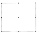
また、レイアウト基準矩形を設定する場合に、該矩形の特徴点の1点を、後述するレイアウト処理時のレイアウト基準点に定めることができる。この矩形の特徴点には、図22に*印で示したように、矩形の角の点(4点)、各辺の中点(4点)、中心点、の9個の点がある。
【0191】
なお、レイアウト基準点は、あらかじめ特定の1点を決めておかなくても、レイアウト処理時に選択することもできる。その場合は、要素のレイアウト基準点を変更する変換(平行移動)が発生する。
【0192】
また、レイアウト基準矩形を設定するには、次のような方法がある。
【0193】
(1)任意矩形:作画エリア62上の任意の2点の位置を、任意指定、点指定、特徴点指定、交点指定、線上点指定、のいずれかの方法で指定することによって、指定した2点を対角点とする矩形を設定する。
【0194】
このうち、任意指定以外の、要素選択を伴う方法では、レイアウト基準矩形を設定する対象の要素、この例の場合では、グループ化された要素のいずれかを選択することが普通であるが、それ以外の要素を選択することも可能である。
【0195】
グループ化された要素に対して、構成要素の1つである円を選び、その円の中心点を特徴点指定、他の1点を任意指定して、レイアウト基準矩形とした場合の例を、図23に示す。
【0196】
(2)外接矩形:次のような外接矩形を算出する。
【0197】
・要素全体の外接矩形:対象とする要素全体の外接矩形を算出する。グループ化された要素の場合は、グループを構成する全要素についての外接矩形を算出する。
【0198】
グループ化された要素に対して、外接矩形を算出し、それをレイアウト基準矩形とした場合の例は、すでに、図21に示した通りである。
【0199】
・要素を構成する任意の要素の外接矩形:複数の要素を持つ、グループ図形の場合には、要素を構成する任意の要素を選択し、その外接矩形を算出することもできる。
【0200】
グループ化された要素に対して、構成要素の1つである円を選び、その円の外接矩形を算出し、それをレイアウト基準矩形とした場合の例を、図24に示す。
【0201】
以上、シンボルの構成要素をグループ化し、シンボルとして登録する手順を説明した。
【0202】
次に、登録されたシンボルを呼び出して、印刷データとしてレイアウトする処理について説明する。
【0203】
(C)シンボルの呼び出しとレイアウト
図25に、登録されたシンボルを呼び出して、印刷データとしてレイアウトする手順を説明するフローチャートを示す。
【0204】
まず、レイアウトしたいシンボルを選択する(ステップS2501)。
【0205】
具体的には、以下のような処理を行なう。
【0206】
まず、外部記憶装置33などに記憶されたシンボルを呼び出すために、メインパネル61上のボタン65中のコマンド「シンボル」のボタンを、ボタン選択するか、または、文字入力エリア64で、コマンド「シンボル」の名称を、キーボード11から入力する。
【0207】
すると、表示装置41には、図26に示すような、シンボルレイアウトパネル2601が、表示される。そして、保存されているシンボル名称一覧2602の中から、レイアウトしたいシンボルを、マウス12で選択する。また、その代わりに、シンボル名称入力エリア2604で、シンボル名称を、直接キーボード11から入力することもできる。その場合、シンボル名称一覧2602の選択状態は、シンボル名称入力エリア2604での入力処理と連動して変化する。
【0208】
記憶されているシンボルの数が多い場合には、シンボル検索条件入力エリア2603で、シンボル名称の一部をキーボード11から入力後に、リターンキーを押してもよい。その場合、入力した条件に該当するシンボル名称のみが、シンボル名称一覧2602に表示されるので、この中から、レイアウトしたいシンボルを、マウス12で選択すればよい。
【0209】
また、シンボルを選択する際に、名称だけでなく形状を見てから選択を行ないたい、という場合のために、必要に応じて、シンボルレイアウトパネル2601の、「一覧」ボタンを、ボタン選択することによって、図27に示すような、シンボル形状一覧パネル2701が、表示装置41に表示される。
【0210】
シンボル形状一覧が、複数ページにわたる場合は、総ページ数がシンボル形状一覧パネル2701に表示されるので、ページ番号入力エリア2702に、キーボード11で、直接ページ番号を入力するか、前ページボタン2703、または、次ページボタン2704を、ボタン選択することによって、現在表示されているページの、前後のページを表示することができる。
【0211】
そして、シンボル形状一覧2705から、レイアウトしたいシンボルを、マウス12で選択すると、シンボル名称一覧2602の選択状態は、これと連動して変化する。
【0212】
また、選択したシンボルの内容を、詳細に確認したい場合には、シンボルレイアウトパネル2601の、「内容」ボタンを、ボタン選択することによって、図28に示すような、シンボル内容確認パネル2801が、表示装置41に表示される。
【0213】
シンボル内容確認パネル2801には、シンボルの形状の他、レイアウト基準矩形などの情報も同時に表示される。図中、点線で示した矩形がレイアウト基準矩形であり、この図の場合、シンボル全体の外接矩形が、レイアウト基準矩形となっている。
【0214】
このようにして、レイアウトするシンボルが決まったら、次に、レイアウト基準位置を選択する(ステップS2502)。
【0215】
レイアウト基準位置は、シンボルレイアウトパネル2601上のレイアウト基準位置選択ボタン2605の中から1個を、ボタン選択することによって、選択することができる。このレイアウト基準位置選択ボタン2605の中に示された9つの基準位置は、それぞれレイアウト基準矩形の9個の特徴点に対応している。
【0216】
レイアウト基準位置を選択すると、シンボルデータファイルに保存されている、シンボルを構成する各要素の座標データは、RAM32に呼び出される際に、選択されたレイアウト基準位置からの相対座標での表現に変換される。
【0217】
また、レイアウトする際に必要な情報として、レイアウトサイズと、レイアウト角度を、入力する(ステップS2503)。
【0218】
レイアウトサイズとは、シンボルをレイアウトする際の大きさを指定するもので、例えば、レイアウト基準矩形の高さか幅の、一方を指定すればよい。その手順は、シンボルレイアウトパネル2601の、レイアウトサイズ選択ボタン2606の「高さ」ボタンまたは「幅」ボタンのいずれかを、ボタン選択した後に、レイアウトサイズ入力エリア2607に、キーボード11で、高さまたは幅の数値を入力すればよい。
【0219】
レイアウトサイズ入力エリア2607に、例えば、「0」などの特別な数値を入力した場合に、シンボルデータファイルに保存されている大きさのままで、シンボルをレイアウトするといったことも可能である。
【0220】
レイアウト角度とは、シンボルをレイアウトする際の角度を指定するもので、例えば、レイアウト基準矩形の、水平な辺(上辺または底辺)が、X軸の正方向となす角度で指定すればよい。その手順は、シンボルレイアウトパネル2601の、レイアウト角度入力エリア2608に、キーボード11から角度の数値を入力すればよい。
【0221】
以上の情報をすべて入力した後、シンボルのレイアウトを実行する場合には、シンボルレイアウトパネル2601の「実行」ボタンを、ボタン選択し、シンボルをレイアウトするのをやめる場合には、「取消」ボタンを、ボタン選択する。
【0222】
次に、選択されたシンボルを、作画エリア62においてレイアウトする位置を指定する(ステップS2504)。
【0223】
シンボルのレイアウト位置を指定する方法には、次のものがある。
(1)点レイアウト:作画エリア62上の任意の位置を、任意指定、点指定、特徴点指定、交点指定、線上点指定、のいずれかの方法で指定する。この場合、指定した位置に、レイアウトするシンボルの、レイアウト基準位置が一致するように、レイアウトされる。
(2)矩形レイアウト:作画エリア62上に、印刷データとしてすでに存在する矩形を、要素選択によって指定する。この場合、シンボルレイアウトパネル2601で指定したレイアウト基準位置とレイアウト角度によらず、指定した矩形の左上点に、レイアウトするシンボルの、レイアウト基準矩形の左上点が一致し、かつ、指定した矩形の左上点をはさむ2辺に、レイアウト基準矩形が沿うように、レイアウトされる。
【0224】
また、シンボルレイアウトパネル2601で、レイアウトサイズを、高さで指定している場合は、指定した矩形の高さに、レイアウト基準矩形の高さが一致するように、幅で指定している場合は、指定した矩形の幅に、レイアウト基準矩形の幅が一致するように、レイアウトされる。
【0225】
以上の操作が終わると、CPU21は、外部記憶装置33から呼び出されたシンボル要素のデータを、印刷データとして、RAM32に登録する(ステップS2505)。
【0226】
また、この際、ステップS1303で求めた、シンボル要素の外接矩形のデータを、シンボル要素のデータの一部として保存する(ステップS2506)。外接矩形のデータを要素データの一部として保持しておけば、例えば、指定した要素を作画エリア62いっぱいに表示したい、というような場合に、再度、輪郭情報を抽出する必要がない。
【0227】
そして、CPU21は、作成されたシンボル要素を、作画エリア62に表示する(ステップS2507)。
【0228】
なお、ステップS2506で保存した外接矩形を、明示的に作成するには、メインパネル61上のボタン65中の、矩形を描画するコマンド「矩形」のボタンを、ボタン選択するか、または、文字入力エリア64で、コマンド「矩形」の名称を、キーボード11から入力した後、コマンドメニュー67の「外接矩形」メニューを、ボタン選択してから、外接矩形を作成したい要素を、要素選択すればよい。
【0229】
以下、上記の方法で呼出したシンボルをレイアウトした場合の具体的な表示例を示す。
【0230】
図29は、シンボルの外接矩形をレイアウト基準矩形に設定し、矩形の左下点をレイアウト基準位置に選び、レイアウトサイズを高さで50mmと指定し、レイアウト角度を30度と指定して、当該シンボルを点レイアウトした場合の例である。なお、この図29では、説明のために、レイアウト基準矩形を同時に表示しているが、実際には、シンボルのみが表示される。もちろん、レイアウト基準矩形を同時に表示するように、仕様変更することも可能である。
【0231】
図30は、シンボルの外接矩形をレイアウト基準矩形に設定し、矩形レイアウトした場合の例である。図30(a)が、レイアウトサイズで高さを設定している場合であり、図30(b)が、レイアウトサイズで幅を設定している場合である。両図中において、破線で示した矩形が、レイアウトの対象となる矩形であり、実線で示した矩形が、レイアウト基準矩形である。なお、この図30では、説明のために、レイアウト基準矩形を同時に表示しているが、実際には、シンボルのみが表示される。もちろん、レイアウト基準矩形を同時に表示するように、仕様変更することも可能である。
【0232】
以上、登録されたシンボルを呼び出して、印刷データとしてレイアウトする手順を説明した。
【0233】
また、以上、図8に示すようなシンボルを作成する手順を、(A)基本図形を印刷データとしてレイアウトする、(B)シンボルの構成要素をグループ化し、シンボルとして登録する、(C)登録されたシンボルを呼び出して、印刷データとしてレイアウトする、という、3つのフローに分けて説明した。
【0234】
○シンボルの履歴管理
また、本実施形態に係る情報処理装置においては、シンボルの履歴を管理することができる。
【0235】
以下、シンボルデータファイルのキーとして、シンボル名称に加えて、シンボルを作成または更新した時間を保持することによって、シンボルの履歴を管理する場合について説明する。
【0236】
まず、例えば、時間順に、次のように、シンボルデータと印刷データの作成または変更を行なったとする。
【0237】
1.シンボル1を作成
(登録シンボル内容:SYM1−a)
2.シンボル1を1回変更
(登録シンボル内容:SYM1−b)
3.シンボル1を含む印刷データ1を作成
4.シンボル1を2回変更
(登録シンボル内容:SYM1−c、d)
5.シンボル1を含む印刷データ1を呼出
上の1から5は、時間の経過および作業内容を表す。1、2、4の、登録シンボル内容とは、シンボル名称「SYM1」に、時間キー「a(または、b、c、d)」を付加した名称で、シンボルが変更されていることを表している。
【0238】
1の時点で、シンボル1を作成すると、登録シンボル内容は、SYM1−aである。
【0239】
2の時点で、シンボル1を1回変更すると、登録シンボル内容は、SYM1−bである。
【0240】
3の時点で、印刷データ1を新規に作成し、シンボル1を貼り付けると、シンボル1の最新の状態であるSYM1−bのファイルが読み込まれる。印刷データファイルにも、SYM1−bの名称で保存される。
【0241】
4の時点で、シンボル1を2回変更すると、登録シンボル内容は、それぞれ、SYM1−c、SYM1−dである。
【0242】
5の時点で、シンボル1を含む印刷データ1を呼び出すと、シンボル1には、SYM1−aからSYM1−dまでの4つの状態のファイルが存在するので、ユーザーは、この中から1つを選択して、呼び出すことができる。
【0243】
複数の時点の状態を持つシンボルを含む印刷データファイルを呼び出した場合には、CPU21は、作画エリア62に、図31に示すような、シンボル状態選択パネル3101を表示する。
【0244】
このシンボル状態選択パネル3101上で、「保存時」ボタンを、ボタン選択すると、印刷データファイルには、印刷データ保存時点でのシンボル1の最新状態であるSYM1−bの名称が保存されているので、SYM1−bのシンボルデータファイルが読み込まれる。また、印刷データ上でのシンボル名称は、SYM1ーbのままである。
【0245】
印刷データを作成した時点での図面を、そのまま、再度、イメージセッター52などの印刷装置で印刷したい、という場合などに、このような選択を行なう。
【0246】
また、シンボル状態選択パネル3101上で、「最新」ボタンを、ボタン選択すると、印刷データファイル呼び出しの時点でのシンボル1の最新の状態であるSYM1−dの、シンボルデータファイルが読み込まれる。そして、印刷データ上でのシンボル名称も、SYM1ーdに、置き換えられる。
【0247】
過去に作成した印刷データに、最新の状態のシンボルを反映させて、現在の規格に適合した形で、再度、イメージセッター52などの印刷装置で印刷したい、あるいは、印刷データを変更したい、という場合などに、このような選択を行なう。
【0248】
また、シンボル状態選択パネル3101上で、「任意」ボタンを、ボタン選択すると、CPU21は、作画エリア62に、図32に示すような、シンボル日時入力パネル3201を表示する。
【0249】
このシンボル日時入力パネル3201上で、ユーザーが呼び出したいシンボルを作成または変更した時点の日時を、日入力エリア3202、および時入力エリア3203に、キーボード11から入力して、「実行」ボタンを、ボタン選択すると、CPU21は、入力された日時の時点での、シンボル1の最新の状態のシンボルデータファイルを読み込んで来る。例えば、SYM1−cが作成された日時より以後で、SYM1−dが作成された日時より以前の、任意の日時を入力した場合には、SYM1−cのシンボルデータファイルが読み込まれる。
【0250】
なお、このような履歴管理は、シンボルに限られるものではなく、イラストに適用することも可能である。
【0251】
○テキストの作成
次に、文字データを作成する例として、図33に示すようなテキストを作成する場合について説明する。
【0252】
図34に、テキストを印刷データとしてレイアウトする手順を説明するフローチャートを示す。
【0253】
まず、テキストをレイアウトするために必要な情報を入力する(ステップS3401)。
【0254】
具体的には、以下のような処理を行なう。
【0255】
まず、メインパネル61上のボタン65中のコマンド「テキスト」のボタンを、ボタン選択するか、または、文字入力エリア64で、コマンド「テキスト」の名称を、キーボード11から入力する。
【0256】
すると、表示装置41には、コマンドメニュー67が表示される。コマンドメニュー67の項目には、
(1)新規:これから新規にテキストを作成する。
(2)修正:すでに作成されているテキストを修正する。
がある。ユーザーは、いずれかのメニュー項目をボタン選択することによって、テキストの編集を行なう。
【0257】
ここで、「新規」メニューをボタン選択すると、表示装置41には、図35に示すような、テキスト編集パネル3501が、表示される。
【0258】
このテキスト編集パネル3501上で、テキストを作成するために必要な情報として、テキストをレイアウトするための情報(レイアウト基準位置、行揃え位置)、文字列データ、文字データの印刷属性(書体名称、基準文字高さ、文字サイズ、平体率、長体率、ベース角、斜体角、字間、行間)を入力する。
【0259】
その際、レイアウト基準位置は、レイアウト基準位置選択ボタン3503における、レイアウト基準矩形の9個の特徴点を示すボタンの中から1個を、ボタン選択することにより指定される。このレイアウト基準位置の指定内容は、点レイアウトの際に有効となる。
【0260】
また、行揃え位置は、行揃え位置選択ボタン3504における、左揃え、右揃え、中央揃え、両端揃え、の4個のボタンの中から1個を、ボタン選択することにより指定される。この行揃え位置の指定内容は、矩形レイアウトの際に有効となる。
【0261】
なお、ここで言及した、レイアウト基準矩形の設定方法、および点レイアウト/矩形レイアウトの方法については、後述する。
【0262】
また、コマンドメニュー67の項目から「修正」メニューをボタン選択すると、ユーザに対して、修正するテキストを選択するように求める指示が、ガイダンスエリア68に表示される。ここで、ユーザーが、この指示に従って、修正したいテキストを要素選択すると、表示装置41には、要素選択されたテキストの現在の状態を表示したテキスト編集パネル3501が、表示される。
【0263】
このテキスト編集パネル3501上で既に設定されている、テキストをレイアウトするための情報、文字列データ、文字データの印刷属性、のうち、修正が必要なデータを修正する。
【0264】
なお、これ以降のステップは、「新規」メニューをボタン選択した場合について説明するが、「修正」メニューをボタン選択した場合でも、テキスト編集パネル3501に、既に設定されている値が表示される点以外は、基本的には、「新規」メニューをボタン選択した場合と同様である。
【0265】
次に、テキストの文字列データを、文字列入力エリア3506に、キーボード11から入力する(ステップS3402)。
【0266】
そして、文字データの印刷属性を付加して、印刷データとして使用できるようにする(ステップS3403)。文字データの印刷属性の種類については、前述した通りである。
【0267】
例として、図36に、印刷属性の付加されていない状態の文字データと、付加されている状態の文字データを示す。印刷属性が付加されていない状態とは、前述した印刷属性データの構造の中で、属性設定フラグが無効となっている場合であり、上記の文字データは、予め設定されているデフォルトの形状や大きさで表現される。
【0268】
ここで、印刷属性を編集するには、印刷属性編集エリア3505の各項目の中から、編集したい印刷属性の文字入力エリアを、マウス12またはキーボード11で指示した後、キーボード11で数値データを入力すればよい。
【0269】
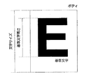
この印刷属性のうち、「基準文字高さ」とは、書体ごとにユーザーが定めた基準文字の可視部分の高さのことで、同一書体の基準文字の「文字サイズ」とは、一般的に比例関係にある。
【0270】
図37に、基準文字として大文字の「E」を定めた場合の、基準文字高さと文字サイズの関係を示す。
【0271】
印刷属性編集エリア3505の、基準文字高さと文字サイズのデータは、どちらか一方のデータを設定すれば、他方のデータはそれに応じて、自動的に更新される。
【0272】
テキスト編集パネル3501上で、最後に設定した文字データの印刷属性は、CPU21によって、カレントな印刷属性として、RAM32に保存されるので、次にテキストを新規に作成する際には、テキスト編集パネル3501に表示されるカレントな印刷属性の一部を変更するだけでよい。
【0273】
また、プログラムを終了する際に、CPU21は、カレントな印刷属性を、外部記憶装置33に保存し、次に、プログラムを実行する際に、再び、RAM32に、読み込んで来るので、プログラムを実行するたびに、カレントな印刷属性を設定し直す必要もない。カレントな印刷属性は、ユーザーによらず共通のものと、ユーザーが各自設定した個別のものを、別々に、RAM32や外部記憶装置33に、保存しておくこともできる。
【0274】
以上の操作を終えたら、ユーザーは、テキスト編集パネル3501の、「実行」ボタンを、ボタン選択し、テキストを作成するために必要な情報(テキストをレイアウトするための情報、文字列データ、文字データの印刷属性)を確定する。
【0275】
このようにして、テキストを作成するために必要な情報が確定されると、CPU21は、設定された内容に従って、テキストのデータを作成し、その輪郭情報を抽出する(ステップS3404)。
【0276】
図38に、図33に示したテキストの輪郭情報を抽出した結果を示す。
【0277】
この輪郭情報を抽出する方法としては、前述した、
(1)そのまま表示装置に表示する方法
(2)一時的に拡大して表示装置に表示する方法
(3)幾何学的な手法による方法
(4)印刷装置に相当するソフトウエアまたはハードウエアに出力する方法
のいずれかの方法を取ることができる。
【0278】
なお、文字データの場合、(3)の方法を取るためには、文字データの形状が、幾何学的な形状で与えられている必要がある。
【0279】
次に、ステップS3404で抽出した輪郭情報から、CPU21は、テキストの外接矩形を計算する(ステップS3405)。外接矩形の計算方法は、図13のステップS1303における方法と同様である。
【0280】
なお、外接矩形を明示的に作成するには、矩形を描画するコマンド「矩形」のボタンを、メインパネル61上のボタン65からボタン選択するか、文字入力エリア64で、コマンド「矩形」の名称をキーボード11から入力し、さらに、コマンドメニュー67上の「外接矩形」メニューを、ボタン選択してから、外接矩形を作成したい要素を、要素選択すればよい。
【0281】
また、テキストの場合、基準文字高さがレイアウトの基準として使われるので、ここで、基準文字の輪郭情報から、基準文字高さを計算する(ステップS3406)。この際、ステップS3402で入力された文字列に基準文字が含まれているか否かによらず、ステップS3403で設定された印刷属性に従って基準文字を作成した場合の、可視部分の高さを計算する。
【0282】
この基準文字高さは、同一書体の基準文字の文字サイズとは、一般的に比例関係にあるので、各書体について、あらかじめ、基準文字高さと、基準文字の文字サイズの比とを、その輪郭情報から計算して、外部記憶装置33に保存しておけば、テキストを作成するたびに、ステップS3406の処理を行なう必要はない。
【0283】
次に、テキストのレイアウト基準情報として、レイアウト基準矩形を設定する(ステップS3407)。レイアウト基準矩形は、テキストの各行ごとに設定する。
【0284】
上述したシンボルの例では、レイアウト基準矩形を設定する際に、
(1)任意矩形
(2)外接矩形
を用いる場合を説明したが、テキストの場合は、
(3)基準文字高さと文字列の可視部分幅で決まる矩形
を、レイアウト基準矩形とする。
【0285】
ここで、基準文字高さは、ステップS3406で求まっており、また、文字列の可視部分幅は、ステップS3405で求めた外接矩形の幅に等しいので、これより、レイアウト基準矩形の左下点と右上点は、
左下点(輪郭情報の最小のX座標,文字列に基準文字が含まれていると仮定した場合の基準文字の輪郭情報の最小のY座標)
右上点(輪郭情報の最大のX座標,文字列に基準文字が含まれていると仮定した場合の基準文字の輪郭情報の最大のY座標)
と与えられる。
【0286】
図39に、図33で示したテキストに対して設定した、テキストのレイアウト基準矩形と、9個のレイアウト基準位置を示したものを示す。図中、実線で示した矩形が、テキストの各行のレイアウト基準矩形であり、また、図中、*印で示した点が、レイアウト基準位置である。
【0287】
次に、テキストを、作画エリア62にレイアウトする位置を指定する(ステップS3408)。
【0288】
テキストのレイアウト位置を指定する方法には、次のものがある。
【0289】
(1)点レイアウト:作画エリア62上の任意の位置を、任意指定、点指定、特徴点指定、交点指定、線上点指定、のいずれかの方法で指定する。この場合、指定した位置に、ステップS3401で指定された、テキストの先頭行のレイアウト基準位置が一致するように、レイアウトされる。
【0290】
図40に、レイアウト基準矩形の左下点をレイアウト基準位置に選び、テキストを点レイアウトした場合の例を示す。図中、*印で示した位置が、レイアウト位置である。なお、この図40では、説明のために、レイアウト基準矩形を、実線で同時に表示しているが、実際には、テキストのみが表示される。もちろん、レイアウト基準矩形を同時に表示するように、仕様変更することも可能である。
【0291】
(2)矩形レイアウト:作画エリア62上に、印刷データとしてすでに存在する矩形を、要素選択によって指定する。この場合、テキストの先頭行のレイアウト基準矩形の上辺が、指定した矩形の上辺に沿うように、かつ、ステップS3401で指定された、行揃え位置に従って、次のようにレイアウトされる。
・左揃え:テキストの各行のレイアウト基準矩形を、指定した矩形の左辺に揃えてレイアウトする。
・右揃え:テキストの各行のレイアウト基準矩形を、指定した矩形の右辺に揃えてレイアウトする。
・中央揃え:テキストの各行のレイアウト基準矩形が、指定した矩形の幅の中央に位置するようにレイアウトする。
・両端揃え:テキストの各行のレイアウト基準矩形の幅が、指定した矩形の幅に一致するように、各行のテキストの字間を調整してレイアウトする。
【0292】
図41に、テキストを矩形レイアウトした場合の例を示す。図中、実線で示した矩形が、レイアウトする対象となる矩形である。図41(a)が左揃えの場合、図41(b)が右揃えの場合、図41(c)が中央揃えの場合、図41(d)が両端揃えの場合である。なお、この図41では、説明のために、レイアウト基準矩形を、破線で同時に表示しているが、実際には、テキストのみが表示される。もちろん、レイアウト基準矩形を同時に表示するように、仕様変更することも可能である。
【0293】
以上の処理が終わると、CPU21は、作成されたテキスト要素のデータを、印刷データとして、RAM32に登録する(ステップS3409)。
【0294】
また、この際、ステップS3405で求めた、テキスト要素の外接矩形のデータを、テキスト要素のデータの一部として保存する(ステップS3410)。
【0295】
このように、外接矩形のデータを、要素データの一部として保持しておけば、例えば、指定した要素を作画エリア62いっぱいに表示したい、というような場合に、再度、輪郭情報を抽出する必要がない。
【0296】
最後に、CPU21は、作成されたテキスト要素を、作画エリア62に表示する(ステップS3411)。
【0297】
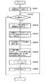
本実施形態では、以上のようなテキストの新規作成、及び修正に加えて、特定文字位置を指定して文字列の配置を行う。
【0298】
テキストの「新規」メニューをボタン選択すると、表示装置41には、図35に示すような、テキスト編集パネル3501が表示される。テキスト編集パネル3501の特定文字選択ボタン3507の「標準」または「設定」のどちらかのボタンを選択し、実行することにより特定文字位置指定で新規に文字列を作成する。
【0299】
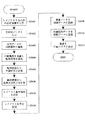
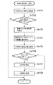
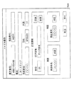
図42はテキストの新規作成において特定文字位置を指定して文字列を配置する手順を説明するフローチャートである。以下、図42を参照して、テキストの新規作成処理を説明するが、まず、ボディ、文字列ボックス、文字輪郭の外接矩形、標準属性について説明する。
【0300】
ボディは上述した通りのものであり、高さが、文字サイズ×平体率であり、幅がその文字の原点から次の文字が通常置かれるべき原点までの水平方向の距離×長体率で表される箱である。よって、ボディ高さは文字サイズと平体率によりどの文字でも同じであるが、ボディ幅は文字ごとに異なる。また、文字列の原点から次の文字列が通常置かれるべき原点までの水平方向の距離を文字列ボックスと呼ぶ。
【0301】
次に、文字輪郭の外接矩形について説明する。文字輪郭は、図34のステップS3404で求めるような輪郭情報であり、その輪郭情報によって表される輪郭に外接する矩形を外接矩形と呼ぶ。外接矩形の計算方法は、図13のステップS1303における方法と同様である。
【0302】
次に、標準属性について説明する。標準属性は、基準となる文字属性のことであり、上述の「(g)文字列属性」において、それぞれの書体について、文字サイズ:100[point]、平体率:100%、長体率:100%、ベース角:0[radium]、斜体角:0[radium]と設定する。また、この標準属性のボディ内の文字輪郭情報を標準属性ボディ内配置位置情報と呼び、図51のようなパラメータで構成される。この様な標準属性を設定することにより、標準属性ボディ内配置位置情報を他の属性への変換に使用しやすくする。また、外部記憶装置33にある標準属性ボディ内配置位置情報のファイルフォーマットを図52に示す。尚、図52に使われているパラメータ名は、図51のパラメータ名と共通している。
【0303】
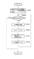
図42において、まず、特定文字の設定を行い、その特定文字の標準属性ボディ内配置位置情報をROM31から読み出す(ステップS4201)。
【0304】
図61は、ステップS4201における特定文字の設定手順を説明するフローチャートである。特定文字の設定に際しては、図61に示されるように、まず、標準特定文字を使用するかどうかの選択をおこなう(ステップS6101)。
【0305】
テキスト編集パネル3501の特定文字選択ボタン3506の標準ボタンを選択すると、標準特定文字の使用が選択される。予め標準特定文字として選択されている一文字の標準属性ボディ内配置位置情報がROM31に格納されている。従って、標準特定文字を使用する場合は、ROM31から標準属性ボディ内配置位置情報をメモリーに読み込む(ステップS6102)。
【0306】
一方、特定文字として、標準特定文字以外の文字を使用する場合は、テキスト編集パネル3501の特定文字選択ボタン3506の設定ボタンを選択し、一文字を入力することにより、特定文字を選択する(ステップS6103)。次に、テキスト編集パネル3501の書体名称一覧3502に選択されている書体の特定文字3507に入力された文字の標準属性ボディ内配置位置情報を作成する。まず、この書体と標準属性を設定して表示原点から選択された特定文字を表示する(ステップS6104)。この場合のボディの大きさやボディないの文字パターンの配置位置はフォント自体が有している。次に、この文字輪郭情報を抽出する(ステップS6105)。抽出した文字輪郭情報から、ボディ内左空白部分の幅、輪郭外接矩形の幅、高さ、右空白部分の幅を求める(ステップS6106)。求めた標準属性ボディ内配置位置情報をメモリーに格納する(ステップS6107)。当該文字列を消去する(ステップS6108)。なお、上述したように、ここでいう「表示」とは、表示装置41に対してデータを送信するという意味であって、必ずしも可視である必要はない。
【0307】
再び図42に戻り、次に、文字列作成処理を行うかどうかの選択をおこなう(ステップS4202)。テキスト編集パネル3501の取消ボタンが選択された場合は、文字列の新規作成処理を終了する。
【0308】
一方、取り消しボタンが選択されていなければ、文字列属性の設定を行う(ステップS4203)。
【0309】
次に、文字データの入力を行う(ステップS4204)。文字データは、キーボード11から入力しRAM32に保存する。
【0310】
次に、特定文字の配置位置を指定する(ステップS4205)。位置の指定方法は、上述のような、点座標入力、任意点入力、点要素選択による点入力、特徴点入力、交点指定、線上点指定の方法がある。ここで指定した配置位置に、文字列内の特定文字のテキスト編集パネル3501の特定文字基準位置選択ボタン3508で選択されている位置がくるようにレイアウトされる。そして、文字列の表示位置を決定し、文字列を表示する(ステップS4206)。
【0311】
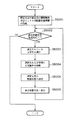
次に、上記ステップS4206において、文字列の表示位置を決定するための処理を説明する。図43は、文字列ボックスサイズを求めて、文字列表示位置を決定する手順を示すフローチャートである。
【0312】
まず、文字列内の特定文字を検索する(ステップS4301)。図44は文字列内における特定文字の検索処理の詳細を説明するフローチャートである。図44において、まず、検索対象文字を当該文字列の先頭文字に設定する(ステップS4401)。そして、検索対象文字が特定文字であるかどうかを判定する(ステップS4402)。特定文字でなければ、検索対象文字を次の文字に設定してステップS4402へ戻る(ステップS4404、S4405)。但し、当該文字列の全ての文字について処理を終えた場合は、次に指定すべき文字が無いので、ステップS4404からステップS4406へ進み、当該文字列内には特定文字が存在しないと判断する。
【0313】
一方、検索対象文字が特定文字であった場合は、当該文字を文字列内の特定文字として決定し本処理を終了する(ステップS4403)。
【0314】
以上の手順を示すように、本実施形態では、文字列先頭から特定文字をサーチし、特定文字が見つかった時点で検索を中止する。よって、文字列内に特定文字が複数存在している場合には、文字列の最も先頭にあるものが特定文字として選択される。また、文字列内に特定文字が存在しない場合には、文字列内に特定文字無しという検索結果を返す。
【0315】
また、特定文字が複数存在している場合に、先頭からいくつめの特定文字を選択するかを、図75のテキスト特定文字検索方法指定パネルでユーザが選択可能にすることもできる。例えば、検索方向設定エリア7502内の末尾ボタンを選択し、順序を1に設定すれば、文字列内の最も後ろにあるものを特定文字として選択できる。
【0316】
以上のようにして、特定文字の検索を終えると、文字列内の特定文字の有無を判定する(ステップS4302)。文字列内に特定文字が存在しない場合は、図60の如きメッセージパネルを表示し、文字列の表示処理を終了し、テキスト編集パネル3501の表示に戻る。
【0317】
一方、特定文字が検索去れば場合は、文字列の先頭文字から検索した特定文字の前文字までの前置文字列ボックスサイズを算出する(ステップS4303)。ここで、前置文字列ボックスとは、当該文字列の先頭から特定文字の直前の文字までの文字で構成される文字列の文字列ボックスである。
【0318】
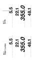
図53に、特定文字をピリオドとし、特定文字基準位置を中とした場合の数字文字列の例を示す。図53において、前置文字列ボックスは、文字列“123”の文字列ボックスである。予って、ステップS4304では、“123”の文字列ボックスサイズ、L5301を求める。文字列ボックスサイズは、書体によりその文字の次文字の原点までの間隔が異なる為、書体が異なるとそのサイズも異なる。本実施形態に係る情報処理装置では、図2で示したように、WYSIWYGの機能が実現されているので、印刷属性の付加されたデータは、印刷時の出力形態と同じ表示形態のイメージで、表示装置41に表示される。
【0319】
例えば、このWYSIWYGの機能が、ディスプレイポストスクリプト(DPS)によって、実現されている場合には、指定属性で文字データを表示し、文字データの、ボディサイズ、及び輪郭情報を抽出するための、ポストスクリプト(PS)の命令(オペレータ)を、文字データに対して、発行してやればよい。よって、図53の例では、指定されている属性で、文字データ”123”を表示して、そのボディサイズをPSの命令により求めればよい。
【0320】
次に、特定文字のボディ内配置位置を算出する(ステップS4304)。図45は特定文字のボディ内配置位置算出の手順を説明するフローチャートである。のフローチャートに手順を示すように、まず、ステップS4501において、ROM31に格納されている標準属性ボディ内配置位置情報から、ステップS4203で設定されたフォント名称の情報を参照する(ステップS4501)。
【0321】
そして、ステップS4502において、図51に示す標準属性ボディ内配置位置情報を、ステップS4203で設定した属性での値に変換する。本実施形態では、標準属性の文字サイズ:Ds[単位:point]、長体率:Dh[単位:%]、平体率:Dw[単位:%]、斜体角度:Dsa[単位:radium]と、設定された属性の文字サイズ:Cs[単位:point]、長体率:Ch[単位:%]、平体率:Cw[単位:%]、斜体角度:Csa[単位:radium]と、標準属性ボディ内配置位置情報の左空白部分サイズ:Dls、右空白部分サイズ:Drs、文字輪郭外接矩形幅:Drw、文字輪郭外接矩形高さ:Drhから、図53で示すような、設定された属性での特定文字ボディ内配置位置情報、左空白部分サイズ:Cls、右空白部分サイズ:Crs、外接矩形幅:Crw、外接矩形高さ:Crh、を算出する。
【0322】
Crw = Drw x ( Cs x Ch / 100 ) / ( Ds x Dh / 100 ) + ( Cs x Cw / 100 ) x tan Csa ; (式4)
Crh = Drh x ( Cs x Cw / 100 ) / ( Ds x Dw / 100 ) ; (式5)
Cls = Dls x ( Cs x Ch / 100 ) / ( Ds x Dh / 100 ) ; (式6)
Crs = Drs x ( Cs x Ch / 100 ) / ( Ds x Dh / 100 ) ; (式7)。
【0323】
次に、文字列の表示開始位置を算出する(ステップS4305)。以下、特定文字基準位置として、図35の選択エリア3508より“中”が選択されているものとして例を示す。
【0324】
図46は文字列の開始位置の算出手順を説明するフローチャートである。図46に示すように、まず、文字列の文字列ボックス左下点から、ステップS4301で検索した特定文字の外接矩形中心までの水平方向距離:LTX、垂直方向距離:LTYを求める(ステップS4601)。ステップS4303で算出した特定文字前文字までの文字列ボックスサイズ水平方向距離:LBX、垂直方向距離:LBYと、ステップS4304で算出した特定文字の左空白部分サイズ:Cls、文字輪郭外接矩形幅:Crw、より、
LTX = LBX + Cls + Crw x 0.5 ; (式8)
LTY = Crh x 0.5 ; (式9)
とする。また、特定文字基準位置が左上に指定されていた場合は、(式8)(式9)は、
LTX = LBX + Cls ; (式10)
LTY = Crh ; (式11)
となり、特定文字基準位置の指定によりLTX,LTYの値が決まる。なお、LBYは、たとえば図35の特定文字基準位置3508で左上を指示し、特定文字の配置位置をオペレータが指定した場合に、文字列の左下点(開始位置)を算出するのに用いられる。
【0325】
文字列の新規作成の場合の文字列開始座標(XSN,YSN)は、ステップS4205で指定された特定文字配置位置(XP,YP)と、前記LTX、LTYより、
XSN = XP - LTX ; (式12)
YSN = YP - LTY ; (式13)
となる(ステップs4602、S4603)。図53に、各値の例を示す。図53において、点:P5301が文字列開始座標、即ちボディ左下点であり、点:P5302が前置文字列ボックス右上点であり、点:P5303が特定文字配置位置である。
【0326】
次に、文字列を作画エリア62に表示する(ステップS4308)。図54に特定文字をピリオドに指定し、特定文字基準位置を中に指定した場合の文字列表示例を示す。図54の例1)は、フォント名称:HelveticaNueu-Bold、文字列方向=水平方向の場合の出力例である。また、図54の例2)は、文字列方向が設定されている文字を円弧と線分の交点に配置した例である。文字列方向が設定されている場合、上述した水平方向が文字列方向に一致する。また、上述した垂直方向は文字列方向に直行する方向となる。図54の例1)は、作画エリア62にある既存点:P5401を要素選択して特定文字位置を指定している。また、図54の例2)では、作画エリア62にある既存の2要素(線分と円弧)を選択し、その交点を特定文字位置としている。
【0327】
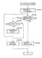
次に、既に作画エリア62に表示されている文字列を選択し、その文字列中の特定文字を指定位置に配置する場合について説明する。図50は、表示中の文字列に対する文字配置処理を説明するフローチャートである。
【0328】
まず、特定文字の設定及び、標準属性ボディ内配置位置情報の作成を行う(ステップS5001)。これは、上述したステップS4201と同処理である。
【0329】
次に、文字列表示位置変更処理を行うかどうかの選択をおこなう(ステップS5002)。ここでテキスト編集パネル3501の取消ボタンが選択された場合は、文字列の表示位置変更処理を終了する。
【0330】
次に、作画エリア62に表示されている文字列から、表示位置変更をおこなう文字列を要素選択する(ステップS5003)。次に、RAM32に登録されている、選択された文字列の文字列データ及び文字属性を参照する(ステップS5004)。次に、特定文字の配置位置を指定する(ステップS5005)。これは、ステップS4205と同処理である。
【0331】
次に、文字列の表示位置を決定し、文字列を表示する(ステップS5006)。これは、ステップS4206とほぼ同じ処理であり、次の点が異なる。
【0332】
(1)文字列開始位置の算出
上述した図46のフローチャートにおいて、既存文字列の表示位置変更処理の場合は、まず、ステップS4601でLTX、LTYを求めた後、処理はステップS4602からステップS4604へ進む。そして、ステップS5005で指定された特定文字配置位置(XP,YP)と、ステップS5004で参照した現在の文字列表示開始位置(XS,YS)から文字列の新文字列開始座標(XSN,YSN)を算出する。
【0333】
たとえば、X座標の場合、
[新文字列開始水平方向座標]
=[現在の文字列表示開始水平方向座標]+[文字列表示開始水平方向移動量]となる。ここで、[文字列表示開始水平方向移動量]は[新たな特定文字位置]−[現在の特定文字位置]で表され、[現在の特定文字位置]は[現在の文字列表示開始水平方向座標]+LTXで表される。したがって、
[新文字列開始水平方向座標]
=[現在の文字列表示開始水平方向座標]+[新たな特定文字位置]−[現在の特定文字位置]
=[現在の文字列表示開始水平方向座標]+[新たな特定文字位置]−([現在の文字列表示開始水平方向座標]+LTX)
=[新たな特定文字位置]−LTXとなる。結局、新たな文字列開始座標(XSN,YSN)は、新たな特定文字配置位置(XP,YP)を用いて、
XSN = XP - LTX ; (式14)
YSN = YP - LTY ; (式15)
となる。
【0334】
(2)文字列の表示
ステップS4306において文字列が作画エリア62に表示されている場合には、文字列の作画エリアからの消去を行う(ステップS4307)。消去処理は、作画エリアから不可視にするとともに、RAM32に登録されているデータも削除する。
【0335】
以上の説明では、文字列の配置に際して、当該文字列の先頭文字から特定文字の直前の文字までの前置文字列について文字列ボックス(前置文字列ボックス)を求めて文字列の配置を決定した。しかしながら、文字列の配置に関しては、このような形態に限られるものではない。以下、他の形態として、前置文字列と特定文字からなる文字列の外接矩形を用いることも可能である。以下、このような外接矩形を用いた方式を説明する。
【0336】
図47は、前置文字列と特定文字からなる文字列の外接矩形を用いた文字列表示位置決定の手順を説明するフローチャートである。図47を参照して、上述のステップS4206、およびステップS5006の表示位置決定処理において、文字列輪郭に対する外接矩形情報を使用して、文字列の新表示開始位置を算出する手順を説明する。なお、図47で示される処理は、上述の図43で示される処理と基本的には同処理であるが、次の点が異なる。
【0337】
(1)文字列の先頭から特定文字までの文字列の外接矩形(以下、前方文字列外接矩形)を算出する(ステップS4703)。
【0338】
図56に、特定文字を“ピリオド”とした場合の数値データの例を示す。この場合、文字列“123.”の開始点から、ピリオドの外接矩形右端までのサイズL56を求める。まず、WYSIWYGの機能を使用し、文字データ“123.”を表示してその文字列ボックスサイズL561、及び輪郭情報抽出、及び、抽出した輪郭情報の外接矩形L562(前方文字列が異説矩形)を求める。また、このとき、文字列開始点P56を原点(0,0)として文字列ボックスサイズ、及び前方文字列外接矩形を求めることにより、文字列開始点P56から前方文字列外接矩形の左端までの距離L563が算出できる。よって、L56は、
L56 = L562 + L563 (式16)
となる。
【0339】
(2)ステップS4703で求めたL56を使用して、文字列の開始位置を算出する(ステップS4705)。
【0340】
図48にその手順を記述するフローチャートを示す。まず、ステップS4703で算出した、特定文字輪郭外接矩形中心までの文字列ボックスサイズ水平方向距離L56と、ステップS4704(即ちステップS4304と同処理)で算出した特定文字の左空白部分サイズ:Cls、文字輪郭外接矩形幅:Crwより、ステップS4601と同様のLTX、LTYを求める(ステップS4801)。
【0341】
特定文字基準位置が中であるとすると、
LTX = L56 - Crw x 0.5 ; (式17)
LTY = - Crh x 0.5 ; (式18)
となる。また、特定文字基準位置が右下であるとすると、以下のような値となり、特定文字基準位置によりLTX,LTYの値が変わる。
【0342】
LTX = L56 ; (式19)
LTY = 0 ; (式20)。
【0343】
次の、新文字列開始座標を求める処理(ステップS4802、S4803、S4804)は、前記ステップS4602、S4603、S4604と同様の処理である。
【0344】
以上のようにして、前方文字列外接矩形を用いて表示位置を決定することができる。
【0345】
また、本実施形態では、上記のいずれの方式においても、作画エリア62に表示されている文字列の特定文字の文字輪郭外接矩形中心の水平方向座標のみを指定位置にあわせることができる。この場合、ステップS4305、またはS4705の新文字列開始位置を算出する処理において、水平方向座標のみをステップS4305、またはS4705のように算出し、垂直方向座標は変更しないようにする。
【0346】
例えば、標準特定文字をピリオド、特定文字基準位置を下とする、選択した文字列内のピリオドの水平方向位置のみを指定配置位置にあうように文字列を移動する機能を、コマンド「テキスト」のコマンドメニュー67(図3)の項目に「小数点合わせ」として用意する。
【0347】
「小数点合わせ」メニューをボタン選択すると、指定配置位置に移動したい文字列を選択するように求める指示が、ガイダンスエリア68に表示される。ここで、ユーザがこの指示に従って、テキストを要素選択する。このとき、キーボード11のShiftキーを押しながら、次々にテキストを要素選択することにより、複数のテキストの選択も行うことができる。テキストを選択すると、特定文字ピリオドの水平方向位置を指定するように求める指示が、ガイダンスエリア68に表示される。特定文字ピリオドの水平方向位置入力には、ステップS4205と同様に、点座標入力、任意点入力、点要素選択による点入力、特徴点入力、交点指定、線上点指定の方法があり、いずれかの方法により入力された点の水平方向座標が特定文字ピリオドの輪郭外接矩形の中心となる。特定文字ピリオド水平方向位置を指定すると、全ての選択されたテキストが、水平方向に移動する。
図55は水平方向位置指定(本例では小数点合わせ)での表示例を示す。
【0348】
また、以上の実施形態では、特定文字に指定された文字について、標準属性ボディ内配置情報を作成しているが、そのような標準属性ボディ内配置情報を予めハードディスクに格納しておいてもよい。
【0349】
図49に標準属性での特定文字ボックス内配置位置情報作成手順を説明するフローチャートを示す。
【0350】
まず、標準特定文字を設定する(ステップS4901)。次に、書体名称および前記標準属性を設定する(ステップS4901)。次に、原点(0,0)を文字列開始位置として特定文字1文字を表示する(ステップS4902)。前記WYSIWYGの機能を使用し特定文字1文字を表示して、図57に示すように、その文字ボックスサイズL5701、及び輪郭情報抽出、及び、抽出した輪郭情報の外接矩形L5702,L5703を求める(ステップS4903)。このとき、文字列開始点P5701を原点(0,0)として輪郭情報外接矩形を求めると、文字左側空白部分の長さL5704が求まる。そして、標準属性での特定文字の文字ボックス内左空白部分の幅:Dls、輪郭外接矩形の幅:Drw、輪郭外接矩形の高さ:Drh、右空白部分の幅:Drsを算出する(ステップS4904)。
【0351】
Dls = L5704 ; (式21)
Drw = L5702 ; (式22)
Drh = L5703 ; (式23)
Drs = L5701 - L5704 - L5702 ; (式24)。
【0352】
そして、上記Dls,Drw,Drh,Drsを外部記憶装置33にフォント名称とともに格納する(ステップS4905)。なお、この標準文字属性文字ボックス内配置位置情報ファイルのフォーマット例は図52で説明した形態を用いれば良い。
【0353】
また、図47で示した、ステップS4703,S4704,S4705の文字列開始位置算出方法を使用し、特定文字の文字ボックス内配置位置情報として、書体名称及び外接矩形の幅:Drw、高さ:Drhのみ格納しておくこともできる。
【0354】
図49のフローに示す処理は、文字列の表示処理において毎回行う必要はなく、そのフォントを初めて使用する前に一度行い、そのデータを外部記憶装置33に格納しておけばよい。外部記憶装置33に格納した情報が、ステップS4201、およびステップS5001でRAM32に読み込まれ使用される。
【0355】
また、図49のフローに示す処理を、全ての使用可能な書体について行い、書体名称、文字ボックス内配置位置情報を外部記憶装置33に格納しておいてもよいし、使用頻度の高い書体についてのみ、行っておいてもよい。そして、データが格納されていない書体については、必要になった場合に、そのデータを作成するようにしてもよい。
【0356】
[印刷データの印刷]
次に、作成された印刷データを、レーザープリンタ51やイメージセッター52などの印刷装置で印刷する手順を説明する。
【0357】
印刷データが、例えば、版下として使用される場合、レーザープリンタ51は、印刷データを、校正刷り(印刷データの確認のための出力)し、また、印刷ログファイルの内容を出力するのに用いられ、イメージセッター52は、印刷データを、清刷り(正式な版下となる高精度な出力)するのに用いられる。
【0358】
本実施形態に係る情報処理装置においては、図形データおよび文字データを、印刷時の出力形態と同じ表示形態のイメージで、表示装置41へ表示する制御を行なう、いわゆるWYSIWYGの機能を有している、
しかしながら、WYSIWYGの機能を有していても、表示装置41は、100DPI程度の解像度しかないため、細かいレイアウトの確認や、ミスのチェックなどを行なうためには、500DPI程度といった、表示装置41よりはるかに高い解像度を持つ、レーザープリンタ51で、印刷データを印刷しなければならない。
【0359】
もちろん、直接、イメージセッター52で印刷データを印刷して、これらの確認を行なうことも可能ではあるが、イメージセッター52は、解像度が3000DPI程度と、極めて高いために、専用の用紙を使用しなければならず、また、印刷のコストがかかり、出力のスピードが遅いなどの欠点があるので、最終的にイメージセッター52で印刷するような場合でも、あらかじめ、レーザープリンタ51で印刷データを印刷して、出力形態の確認を行なっておくのが普通である。
【0360】
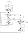
図62に、作成された印刷データを、レーザープリンタ51やイメージセッター52などの印刷装置で印刷する手順を説明するフローチャートを示す。
【0361】
まず、印刷のコマンドを選択する(ステップS6201)。
【0362】
具体的には、以下のような処理を行なう。
【0363】
まず、メインパネル61上のボタン65の中の、コマンド「プリント」のボタンを、ボタン選択するか、または、文字入力エリア64で、コマンド「プリント」の名称を、キーボード11から入力する。
【0364】
すると、表示装置41には、コマンドメニュー67が表示される。コマンドメニュー67の項目には、
(1)校正刷り
(2)部分校正刷り
(3)清刷り
がある。ユーザーが、いずれかのメニュー項目をボタン選択することによって、印刷データの印刷処理が開始される。
【0365】
それでは、まず、ステップS6201において、「校正刷り」メニューがボタン選択された場合について、以下に説明する。
【0366】
「校正刷り」メニューをボタン選択した場合、CPU21によって、印刷装置として、レーザープリンタ51が選択される(ステップS6211)。
【0367】
そして、校正刷りが選択されたものとして、表示装置41には、図63に示すような、校正刷り出力条件設定パネル6301が表示される。校正刷り出力条件設定パネル6301では、次の各条件を設定する。
(1)倍率
(2)部数
(3)紙サイズ
(4)紙方向。
【0368】
まず、実寸の何倍で出力するかを、倍率入力エリア6302に、キーボード11で数値を入力する(ステップS6212)。
次に、同じ印刷データを一度の印刷処理で何部出力するかを、部数入力エリア6303に、キーボード11で数値を入力する(ステップS6213)。
【0369】
次に、紙サイズ選択ボタン6304で、印刷データを印刷する用紙のサイズのボタンを1つ、ボタン選択する(ステップS6214)。ここで選択することのできる紙サイズの種類は、出力するレーザープリンタ51の仕様に従う。
【0370】
次に、紙方向選択ボタン6305で、印刷データを印刷する用紙の紙方向を、縦(Y方向が長い)/横(X方向が長い)/自動(ページ数が最少になる)のいずれかの中から1つ、ボタン選択する(ステップS6215)。
【0371】
校正刷りの出力条件の設定を行なった後、「実行」ボタンを、ボタン選択することによって、出力条件が決定される。
【0372】
次に、印刷データのうち、実際に出力の対象となる要素を、以下のような条件によって決定する(ステップS6216)。
(1)レイヤー:レイヤーとは、個々の要素が所属する、印刷データの仮想的な階層であり、表示上では、要素の色などによって識別できる。レイヤーによって、常に出力の対象となるレイヤー、常に出力の対象とならないレイヤー、ユーザーが出力の対象とするかどうかを選択できるレイヤー、がある。
(2)表示属性:非表示状態に設定されている要素やレイヤーは、出力の対象としない、などの条件である。ユーザーは、要素やレイヤーごとに、この条件を設定できる。
(3)要素種別:常に出力の対象となる要素種別(トンボなど)、常に出力の対象とならない要素種別(点など)、ユーザーが出力の対象とするかどうかを選択できる要素種別(その他の要素種別)、がある。
【0373】
次に、CPU21は、実際に出力の対象となる全ての要素について、ステップS6212で設定した倍率をかけた状態での、要素の外接矩形を計算する(ステップS6217)。
【0374】
その際に、要素の外接矩形が、すでにCPU21によって計算され、要素のデータの一部として、RAM32に保存されている場合には、保存されている外接矩形の情報に、倍率をかけるだけでよい。
【0375】
また、CPU21は、ステップS6214で設定した紙サイズから、印刷データを出力しない、上下左右の各方向の紙マージン部分を除いた、有効出力領域を計算する(ステップS6218)。
【0376】
ここで、紙サイズの情報、紙マージンの大きさの情報は、あらかじめ、外部記憶装置33などに保存されているものを、RAM32に読み込んで使用する。
【0377】
次に、ステップS6217で計算した外接矩形、およびステップS6218で計算した有効出力領域の情報から、CPU21は、印刷データを紙に出力したときの出力範囲と位置を決定する(ステップS6219)。
【0378】
1枚の紙に、印刷データを出力できる場合には、CPU21は、印刷データが紙の中央に出力されるように、出力位置を決定する。ここで、印刷データを、紙の左下、左上、右下、右上、などの位置に出力することも可能である。
【0379】
また、1枚の紙に、印刷データを出力できない場合には、CPU21は、印刷データを複数の紙に分割して出力する。このように、印刷データを、複数の紙に分割して出力する場合、境界部分の印刷データが完全に出力されるように、印刷データの一部をオーバーラップさせて、分割された両方の紙に出力させることもできる。
【0380】
また、ステップS6215で、紙方向を「自動」と選択した場合には、印刷用紙のページ数が最も少なくなるように、縦方向、横方向のいずれかが、CPU21によって選択された上で、出力範囲と位置が決定される。
【0381】
そして、実際に紙に出力する前に、ユーザーが出力範囲の確認を行えるように、CPU21は、作画エリア62に出力範囲を表示する(ステップS6220)。
【0382】
図64に、出力範囲を確認表示した一例を示す。図中の細線で示した矩形が、出力範囲である。これは、印刷データを1枚の紙に出力できる場合で、かつ、紙方向として、縦が選択された場合の例である。
【0383】
図65に、出力範囲を確認表示した別の例を示す。図64とは異なり、これは、印刷データを1枚の紙に出力できずに、4枚の紙に分割して出力する場合で、かつ、紙方向として、横が選択された場合の例である。
ここで、図66に示すような、出力範囲確認パネル6601が表示される。そこで、ユーザーは、ステップS6220で表示された出力範囲を見て、印刷データを実際に紙に出力するかどうかを判断する。ユーザーは、出力範囲が適当であると判断した場合には、出力範囲確認パネル6601において、「実行」ボタンを、ボタン選択し、出力範囲が適当でないと判断した場合には、出力範囲確認パネル6601において、「取消」ボタンを、ボタン選択する(ステップS6221)。
【0384】
ここで、「実行」ボタンが、ボタン選択された場合は、印刷データの他に、出力時に付加される印刷付加情報である、印刷データ名称、出力日付および時間、出力ページ数、などを付加する(ステップS6222)。
【0385】
これらの印刷付加情報のうち、印刷データ名称は、あらかじめユーザーが設定しておいた情報が、RAM32から読み込まれる。また、出力日付および時間、出力ページ数は、CPU21が、出力時に設定する。
【0386】
また、印刷付加情報が出力される、用紙上の位置、文字の印刷属性などの情報は、あらかじめ外部記憶装置33などに保存されているものを、RAM32に読み込んで使用する。
【0387】
そして、印刷付加情報および印刷データが、実際に、レーザープリンタ51から、紙に出力され、いわゆる校正刷り出力が実行される(ステップS6223)。
【0388】
一方、ステップS6221において、「取消」ボタンが、ボタン選択された場合は、印刷データの出力は行なわれずに、校正刷り出力条件設定パネル6301が、再び表示されるので、ステップS6212に戻り、ユーザーは、再度、倍率などの出力条件を設定し直せばよい。
【0389】
それでは、次に、ステップS6201において、「部分校正刷り」メニューがボタン選択された場合について、説明する。
【0390】
「部分校正刷り」メニューを、ボタン選択した場合、CPU21によって、印刷装置として、レーザープリンタ51が選択される(ステップS6231)。
【0391】
このように、部分校正刷りが選択された場合、次に、ユーザに対して、出力する要素を選択するように求める指示が、ガイダンスエリア68に表示されるので、ユーザーは、この指示に従って、要素を選択する。要素の選択方法は、前述の、要素をグループ化する場合と同様、連続要素選択、矩形領域指定、任意領域指定、のいずれかの方法をとればよい(ステップS6232)。
【0392】
要素の選択が終了すると、表示装置41には、図63に示すような、校正刷り出力条件設定パネル6301が表示される。
【0393】
以下、ステップS6212からステップS6223までの処理は、校正刷りの場合と同様であるため、説明を省略する。
【0394】
それでは、次に、ステップS6201において、「清刷り」メニューがボタン選択された場合について、説明する。
【0395】
図67に、印刷データを清刷り出力する手順を説明するフローチャートを示す。
【0396】
まず、「清刷り」メニューを、ボタン選択した場合、CPU21によって、印刷装置として、イメージセッター52が選択される(ステップS6711)。
【0397】
そして、清刷りが選択されたものとして、表示装置41には、図68に示すような、清刷り出力条件設定パネル6801が表示される。清刷り出力条件設定パネル6801では、次の各条件を設定する。
(1)倍率
(2)部数
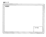
(3)ラベル
(4)図面枠
まず、実寸の何倍で出力するかを、倍率入力エリア6802に、キーボード11で数値入力する(ステップS6712)。
【0398】
次に、同じ印刷データを一度の印刷処理で何部出力するかを、部数入力エリア6803に、キーボード11で数値入力する(ステップS6713)。
【0399】
次に、印刷データに添付するための定型のラベルを、印刷データと共に出力するか否かを、ラベル出力選択ボタン6804で、ボタン選択する(ステップS6714)。このラベルには、版下名称、部品番号、部品名称、作成者名および日付、承認者名および日付、尺度、訂正履歴、などの情報が出力される。
【0400】
次に、図面枠を、印刷データと共に出力するか否かを、図面枠出力選択ボタン6805で、ボタン選択する(ステップS6715)。この図面枠とは、出力した印刷データの、図面としての範囲を示す矩形であって、通常、紙サイズの端から、一定の長さだけ内側にオフセットさせた矩形となる。
【0401】
このようにして、清刷りの出力条件の設定を行なった後、「実行」ボタンを、ボタン選択することによって、出力条件が決定される。
【0402】
次に、出力対象要素を決定し(ステップS6716)、その出力対象要素の外接矩形を計算する(ステップS6717)。これらの処理は、校正刷りの場合の、ステップS6216、及びステップS6217と同様である。
【0403】
次に、ステップS6717で計算された外接矩形の情報から、CPU21は、紙サイズ(印刷データを全て出力できる最小のAnサイズ)および紙方向を決定する(ステップS6718)。
【0404】
清刷り出力の場合、印刷用紙の枚数が少なくなるようにした方が、コスト、スピードなどの点で、効率がよいので、可能ならば、複数の印刷データを、1枚の印刷用紙に出力するようになっている。ここでいう印刷用紙とは、実際に、イメージセッター52で使用する用紙のことで、紙サイズとは異なる。紙サイズとは、単一の印刷データを出力するために必要な領域のサイズのことである。
【0405】
次に、CPU21は、印刷データが紙の中央に出力されるように、出力位置を決定する(ステップS6719)。ここで、印刷データを、紙の左下、左上、右下、右上、などの位置に出力することも可能である。
【0406】
そして、実際に紙に出力する前に、ユーザーが出力範囲の確認を行なえるように、CPU21は、作画エリア62に出力範囲を表示する(ステップS6720)。
【0407】
ここで、図56に示すような、出力範囲確認パネル6601が表示される。そこで、ユーザーは、ステップS6720で表示された出力範囲を見て、印刷データを実際に紙に出力するかどうかを判断する。ユーザーは、出力範囲が適当であると判断した場合には、出力範囲確認パネル6601において、「実行」ボタンを、ボタン選択し、出力範囲が適当でないと判断した場合には、出力範囲確認パネル6601において、「取消」ボタンを、ボタン選択する(ステップS6721)。
【0408】
ここで、「実行」ボタンが、ボタン選択された場合は、次のステップに進む。一方、「取消」ボタンが、ボタン選択された場合は、印刷データの出力は行なわれずに、清刷り出力条件設定パネル6801が、再び表示され、ステップS6212に戻り、ユーザーは、再度、倍率などの出力条件を設定し直すことができる。
【0409】
次に、ステップS6714で「ラベル」の項目を「あり」と選択していた場合には、CPU21は、ラベルデータを作成する(ステップS6722)。
【0410】
図69に、清刷り用ラベルの一例を示す。これは、写真製版用の版下に付けられるラベルの例で、ラベルの項目には、版下番号、部品番号、略式、承認者名、検証者名、作成者名、製品記号、日付、尺度、訂正履歴、などがある。
【0411】
このラベルの枠やタイトル文字などの固定部分の情報は、あらかじめ外部記憶装置33などに保存されているものを、RAM32に読み込んで使用する。また、ラベルの各項目の内容は、印刷データをファイルに保存する際に、図70に示すようなファイル保存パネル7001で入力されて、外部記憶装置33などに保存され、その保存されたものを、RAM32に読み込んで使用する。
【0412】
また、作成者名や承認者名の情報は、ユーザーがパネルから入力するのではなく、CPU21が、現在のユーザー名を認識して設定するようにしてもよい。日付の情報も、CPU21が、現在の日付を設定するようにしてもよい。
【0413】
また、ラベルは、紙サイズの右下などの決められた位置に、決められた大きさで、出力される。ラベルの位置に関しては、このほか、左上、左下、右上、などの位置から選択できるようにしたり、任意の位置を指定できるようにしたりすることも可能である。
【0414】
また、ラベルのフォームを、用途に応じて数種類用意しておいて、外部記憶装置33などに保存しておき、ステップS6714でラベル出力が「あり」と指定された場合に、保存されたフォームを選択できるようにしてもよい。
【0415】
次に、ステップS6715で「図面枠」の項目が「あり」と選択された場合には、CPU21は、図面枠データを作成する(ステップS6723)。
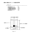
【0416】
図71に、図面枠と紙サイズの関係を示す。この図71では、ラベルは図面枠の右下に設定されている。
【0417】
図面枠の線幅や、紙サイズごとの出力位置と大きさの情報は、あらかじめ、外部記憶装置33などに保存されているものを、RAM32に読み込んで使用する。CPU21は、ステップS6718で決定された、紙サイズに応じた図面枠の出力位置と大きさを決定する。
【0418】
以上の処理により、単一の印刷データを清刷り出力するためのデータが作成される。実際に清刷り出力する際には、複数の印刷データを指定することができるので、継続して、次の印刷データを清刷り出力する場合には、出力条件を設定するステップ(ステップS6712)から、図面枠データを作成するステップ(ステップS6723)までの処理を繰り返す(ステップS6724)。
【0419】
複数の印刷データの指定が終了すると、次に、CPU21は、印刷用紙に、複数の印刷データをどのように配置するかを決定する(ステップS6725)。イメージセッター52に出力する場合の最適な配置とは、印刷用紙の枚数が最も少なくなるように、各印刷データを配置することである。この印刷データの最適配置処理については、後で詳細に説明する。
【0420】
次に、清刷り出力の印刷ログファイルを作成する(ステップS6726)。印刷ログファイルには、以下の情報が記述され、イメージセッター52から出力される版下の出力内容がわかるようになっている。図74に、印刷ログファイルの出力例を示す。
(1)出力時刻、出力者、ページ数:実際に印刷データを出力した日付および時刻、出力者の氏名、ページ数、などを記述する。
(2)印刷用紙の配置図:印刷用紙に、各印刷データがどのように配置されているかの概略図を作成する。配置図には、各印刷データの配置がわかるように、記号を付ける。
(3)出力データのリスト:配置図に示した記号、出力条件の情報(紙サイズ、紙方向、など)、ラベルの情報(版下名称、部品番号、部品名称、作成者名および日付、承認者名および日付、尺度、など)を、リスト形式で記述する。
【0421】
以上で、清刷り出力用のデータは、全て作成されたので、CPU21は、印刷データを、イメージセッター52で印刷する(ステップS6727)。
【0422】
また、印刷ログファイルデータを、レーザープリンタ51で印刷する(ステップS6728)。
【0423】
次に、ステップS6725における印刷データの最適配置処理について、詳細に説明する。ここでは、印刷用紙サイズがAmサイズ、各印刷データの紙サイズがAnサイズ(m>=n)であるとする。
【0424】
図72に、印刷データを最適配置する際のフローチャートを示す。
【0425】
まず、印刷用紙のサイズを指定する(ステップS7201)。使用する印刷用紙サイズが、あらかじめ決まっている場合には、このステップを省略することもできる。
【0426】
次に、出力する各印刷データの紙サイズを大きい順に並べ換える(ステップS7202)。同じ大きさの印刷データの間では、どのような順番でも構わない。
【0427】
そして、CPU21は、出力する印刷データが存在するかどうかを判定する(ステップS7203)。出力する印刷データが存在する場合は、次のステップS6204に進む。出力する印刷データが存在しない場合は、印刷データ最適配置の処理を終了する。
【0428】
次に、出力する印刷データが、カレントな印刷用紙に配置可能かどうかを判定する(ステップS7204)。カレントな印刷用紙に配置可能な場合には、次のステップS6206に進む。配置可能でない場合には、現在の印刷用紙への配置は終了し、次の印刷用紙に着目して、カレントな印刷用紙に設定してから(ステップS7205)、再度、カレントな印刷用紙に配置可能かどうかを判定する。
【0429】
次に、出力する印刷データの方向を変更する必要があるかどうかを判定する(ステップS7206)。方向を変更する必要がある場合には、出力する印刷データを全て90度回転させて方向を変更する(ステップS7207)。方向を変更する必要がない場合には、そのまま、次のステップS7208に進む。
【0430】
そして、出力する印刷データを、カレントな印刷用紙に配置する(ステップS7208)。
【0431】
以上で、単一の印刷データを印刷用紙に配置する処理が終了する。複数の印刷データの全てが、印刷用紙に配置されるまで、出力する印刷データの有無を判定するステップ(ステップS7203)から、出力する印刷データを印刷用紙に配置するステップ(ステップS7208)を繰り返す。
【0432】
例えば、印刷用紙サイズがA1であるとし、A2の印刷データが1枚(名称A21とする)、A3が3枚(A31、A32、A33)、A4が3枚(A41、A42、A43)あったとすると、印刷データは、A21、A31、A32、A33、A41、A42、A43、という順番に並べ換えられる。
【0433】
図73は、このA21からA43までの印刷データを、A1サイズの印刷用紙に、最適配置した結果の一例である。
【0434】
この図73の例では、A21、A31、A32、までは、1枚目の印刷用紙に配置可能であるが、次のA33は、1枚目の印刷用紙に配置不可能となるので、カレントな印刷用紙を、2枚目に移動し、A33は、2枚目の印刷用紙に配置可能となる。
【0435】
また、この図73の例では、例えば、A21の紙方向が縦だった場合に、A21を印刷用紙に配置する際に使用される領域が、横方向となるので、A21の印刷データを全て90度回転させて、方向を変更しなければならない。
【0436】
以上、作成された印刷データを、レーザープリンタ51やイメージセッター52などの印刷装置で印刷する手順を説明した。
【0437】
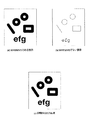
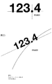
以上説明したように、本実施形態によれば、図55で示されるように複数行の文字列を配置する場合に、例えばピリオドを揃えて、見栄えよく配置することができ、特に有効である。
【0438】
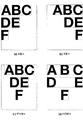
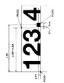
さらに、図58に、本実施形態における特定文字をピリオド、特定文字基準位置を下とした場合の表示例と従来例を示す。図58の(a)および(b)では、"355.0"が斜体角度>0、文字サイズ1.3倍で書かれており、複数の属性の異なる文字列をピリオドの位置で配置している。図58の(b)は、従来例であり、ピリオドのボディの左端が指定位置に配置されている。これに対して、(a)は本実施形態による表示例であり、ピリオドの輪郭の外接矩形における水平方向中心が指定位置に配置されている。この例のように、文字属性の異なる文字列が複数行に配置された場合にも、特定文字の中心点を一致させることができるため、文字列が揃って見える効果がある。
【0439】
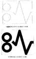
さらに、図59の(a)に特定文字をハイフンとし、特定文字基準位置を下とした場合の複数文字列の表示例を示す。なお、図59の(b)に示されるように、円弧に沿って配置されている文字列の特定文字(図ではハイフン)の位置を指定位置に配置することもできる。
【0440】
なお、本発明は、複数の機器(例えばホストコンピュータ,インタフェイス機器,リーダ,プリンタなど)から構成されるシステムに適用しても、一つの機器からなる装置(例えば、複写機,ファクシミリ装置など)に適用してもよい。
【0441】
また、本発明の目的は、前述した実施形態の機能を実現するソフトウェアのプログラムコードを記録した記憶媒体を、システムあるいは装置に供給し、そのシステムあるいは装置のコンピュータ(またはCPUやMPU)が記憶媒体に格納されたプログラムコードを読出し実行することによっても、達成されることは言うまでもない。
【0442】
この場合、記憶媒体から読出されたプログラムコード自体が前述した実施形態の機能を実現することになり、そのプログラムコードを記憶した記憶媒体は本発明を構成することになる。
【0443】
プログラムコードを供給するための記憶媒体としては、例えば、フロッピディスク,ハードディスク,光ディスク,光磁気ディスク,CD−ROM,CD−R,磁気テープ,不揮発性のメモリカード,ROMなどを用いることができる。
【0444】
また、コンピュータが読出したプログラムコードを実行することにより、前述した実施形態の機能が実現されるだけでなく、そのプログラムコードの指示に基づき、コンピュータ上で稼働しているOS(オペレーティングシステム)などが実際の処理の一部または全部を行い、その処理によって前述した実施形態の機能が実現される場合も含まれることは言うまでもない。
【0445】
さらに、記憶媒体から読出されたプログラムコードが、コンピュータに挿入された機能拡張ボードやコンピュータに接続された機能拡張ユニットに備わるメモリに書込まれた後、そのプログラムコードの指示に基づき、その機能拡張ボードや機能拡張ユニットに備わるCPUなどが実際の処理の一部または全部を行い、その処理によって前述した実施形態の機能が実現される場合も含まれることは言うまでもない。
【0446】
【発明の効果】
以上説明したように、本発明によれば、文字列配置位置を高精度に決定し、出力することが可能となる。
【図面の簡単な説明】
【図1】本発明の一実施形態の情報処理装置のハードウエア構成を示すブロック図である。
【図2】WYSIWYGの機能を説明する図である。
【図3】本実施形態のプログラムのメインパネルを示す図である。
【図4】各要素の特徴点を示す図である。
【図5】交点指定による位置の指定の例を示す図である。
【図6】線上点指定による位置の指定の例を示す図である。
【図7】印刷データファイルの例を示す図である。
【図8】シンボルの例を示す図である。
【図9】基本図形を印刷データとしてレイアウトする手順を説明するフローチャートである。
【図10】図形データに印刷属性を付加した例を示す図である。
【図11】図形データ印刷属性編集パネルを示す図である。
【図12】線ピッチ編集パネル(二点鎖線の例)を示す図である。
【図13】要素のグループ化とシンボルの登録をする手順を説明するフローチャートである。
【図14】矩形領域指定によって対象となる要素が選択された様子を示す図である。
【図15】任意領域指定によって対象となる要素が選択された様子を示す図である。
【図16】シンボルの輪郭情報を抽出した結果の例を示す図である。
【図17】座標データの量子化を説明する図である。
【図18】一時的に要素を拡大表示して輪郭情報を抽出する手順を説明するフローチャートである。
【図19】幾何学的な手法で輪郭情報を抽出する手順を説明するフローチャートである。
【図20】線分列の輪郭情報を幾何学的な手法で抽出した例を示す図である。
【図21】グループ化された要素とその外接矩形を示す図である。
【図22】矩形の特徴点を示す図である。
【図23】任意矩形をグループ図形のレイアウト基準矩形に設定した例を示す図である。
【図24】構成要素の外接矩形をグループ図形のレイアウト基準矩形に設定した例を示す図である。
【図25】シンボルの呼び出しとレイアウトをする手順を説明するフローチャートである。
【図26】シンボルレイアウトパネルを示す図である。
【図27】シンボル形状一覧パネルを示す図である。
【図28】シンボル内容確認パネルを示す図である。
【図29】シンボルを点レイアウトした例を示す図である。
【図30】シンボルを矩形レイアウトした例を示す図である。
【図31】シンボル状態選択パネルを示す図である。
【図32】シンボル日時入力パネルを示す図である。
【図33】テキストの例を示す図である。
【図34】テキストを印刷データとしてレイアウトする手順を説明するフローチャートである。
【図35】テキスト編集パネルを示す図である。
【図36】文字データに印刷属性を付加した例を示す図である。
【図37】基準文字高さと文字サイズの関係を示す図である。
【図38】テキストの輪郭情報を抽出した結果の例を示す図である。
【図39】テキストのレイアウト基準矩形とレイアウト基準位置を示す図である。
【図40】テキストを点レイアウトした場合の例を示す図である。
【図41】テキストを矩形レイアウトした場合の例を示す図である。
【図42】文字列新規作成における文字列配置の手順を説明するフローチャートである。
【図43】前置文字列ボックスサイズを使用して文字列表示位置を決定する手順を説明するフローチャートである。
【図44】文字列内の特定文字検索の手順を説明するフローチャートである。
【図45】特定文字の文字ボックス内配置位置算出の手順を説明するフローチャートである。
【図46】前置文字列ボックスサイズを使用して文字列開始位置を算出する手順を説明するフローチャートである。
【図47】前置文字列外接矩形を使用して文字列表示位置を決定する手順を説明するフローチャートである。
【図48】前置文字列外接矩形を使用して文字列開始位置を算出する手順を説明するフローチャートである。
【図49】標準属性での標準特定文字ボックス内配置位置情報作成の手順を説明するフローチャートである。
【図50】表示中の文字列の文字列配置の手順を説明するフローチャートである。
【図51】文字ボックス及び、標準文字属性文字ボックス内配置位置情報の内容を示す図である。
【図52】標準文字属性文字ボックス内配置位置情報ファイルの例を示す図である。
【図53】特定文字をピリオドとした場合の数値データの表示例を示す図である。
【図54】特定文字をピリオドとした場合の文字列表示例を示す図である。
【図55】水平方向位置指定での文字列表示例を示す図である。
【図56】特定文字をピリオドとした場合の数値データの表示例を示す図である。
【図57】標準属性での特定文字ボックス内配置位置情報をハイフンを例に説明する図である。
【図58】複数文字列表示における従来例との比較を説明する図である。
【図59】特定文字をハイフンとした場合の複数文字列表示例を示す図である。
【図60】テキストの特定文字位置指定作成メッセージパネルの例を示す図である。
【図61】特定文字の設定及び標準属性文字ボックス内配置位置情報の作成の手段を説明するフローチャートである。
【図62】印刷データを出力する手順を説明するフローチャートである。
【図63】校正刷り出力条件設定パネルを示す図である。
【図64】出力範囲を確認表示した例(1枚の紙に出力できる場合)を示す図である。
【図65】出力範囲を確認表示した例(1枚の紙に出力できない場合)を示す図である。
【図66】出力範囲確認パネルを示す図である。
【図67】印刷データを清刷り出力する手順を説明するフローチャートである。
【図68】清刷り出力条件設定パネルを示す図である。
【図69】清刷り用ラベルの例を示す図である。
【図70】ファイル保存パネルを示す図である。
【図71】図面枠と紙サイズの関係を示す図である。
【図72】印刷データを最適配置する手順を説明するフローチャートである。
【図73】印刷データを最適配置した結果の例を示す図である。
【図74】印刷ログファイルの出力例を示す図である。
【図75】テキスト特定文字検索方法指定パネルの例を示す図である。[0001]
[Technical field to which the present invention pertains]
The present invention relates to an information processing apparatus, information processing method, and storage medium having an editing function, and is suitable for use in, for example, an information processing apparatus, information processing method, and storage medium for creating a high definition composition. .
[0002]
[Prior art]
As an example of an information processing apparatus having an editing function, CAD or DTP (Desk) is used to create print data, especially print data for prints such as figures, characters and illustrations to be displayed on the product body, its packages, manuals, etc. There are interactive drawing systems such as Top Publishing.
[0003]
Conventionally, when a character string is arranged so that a specific character in a character string is displayed at a specified position in this type of information processing apparatus, the tab setting position is the specified position, and the body left end of the specific character is the specified position. In general, a method of arranging so as to become is used.
[0004]
[Problems to be solved by the invention]
However, the above conventional example has the following problems.
[0005]
For example, if you set a specific character as a period and try to align the period position of numeric data written on multiple lines to the specified position, use bold font (Bold type) to emphasize one numeric data Or increase the font size or set the italic angle. In such a case, in the above conventional example, the left end of a box in which a certain percentage of blank portions are set in a body of a period, that is, a circumscribed rectangle with respect to a character outline, is arranged at a specified position. For this reason, if there are character strings with different character attributes in this way, the size of the blank part in the body changes for each character string, the character outline shape changes depending on the italic angle, and the positions of the periods are not visible. There was a problem that.
[0006]
In addition, since the position of the specific character is specified by the tab setting position, there is a problem that it is difficult to specify an accurate position.
[0007]
The present invention has been made to solve the above-described problems, and an object thereof is to determine a character string arrangement position with high accuracy.
[0008]
[Means for Solving the Problems]
In order to achieve the above object, an information processing apparatus of the present invention has the following configuration, for example. That is,
Holding means for holding in-body arrangement information representing an arrangement in the body of the specific character according to a predetermined print attribute for the specific character;
Storage means for storing character data;
AboveBased on the print attribute added to the character data stored in the storage means, the body information of the prefix character string configured from the first character of the character string represented by the character data to the character immediately before the specific character is Extracting means for extracting;
An arrangement position designation means for accepting designation of an arrangement position of the specific character in the character string represented by the character data;
Reference position specifying means for receiving specification of a reference position of the specific character;
First calculating means for calculating a size related to a body of the prefix character string from body information of the prefix character string extracted by the extracting means;
Second calculating means for calculating an arrangement position of the specific character in the body based on the arrangement information in the body and a print attribute;
Based on the information calculated by the first and second calculation means,AboveThe reference position of the specific character whose specification is accepted by the reference position specifying meansAboveThird calculation means for calculating the leading position of the character string when the character string is arranged at the arrangement position received by the arrangement position designation means;
Layout means for laying out the character string from the head position calculated by the third calculation means.
[0009]
Moreover, the information processing method of this invention for achieving said objective is equipped with the following processes, for example. That is,
Specific charactersIn-body arrangement information indicating the arrangement of the specific character in the body according to a predetermined printing attribute.HoldFirst memoryAnd character dataRememberAn information processing method by an information processing device including a second memory,,
Of the information processing apparatusBased on the printing attribute added to the character data, the extracting means extracts body information of a prefix character string composed of the first character of the character string represented by the character data to the character immediately before the specific character. An extraction process to
Of the information processing apparatusAn arrangement position designating step for accepting designation of an arrangement position of the specific character in the character string represented by the character data;
Of the information processing apparatusA reference position specifying means for receiving a specification of a reference position of the specific character;
Of the information processing apparatusA first calculation step in which a first calculation means calculates a size related to a body of the prefix character string from body information of the prefix character string extracted by the extraction step;
Of the information processing apparatusA second calculating step, wherein the second calculating means calculates the arrangement position of the specific character in the body based on the in-body arrangement information and the print attribute;
Of the information processing apparatusBased on the information calculated in the first and second calculation steps, the third calculation means sets the reference position of the specific character specified in the reference position specifying step to the position specified in the arrangement position specifying step. A third calculation step of calculating the leading position of the character string when arranged;
Of the information processing apparatusThe layout means includes a layout step of laying out the character string from the head position calculated in the third calculation step.
[0010]
DETAILED DESCRIPTION OF THE INVENTION
FIG. 1 is a block diagram showing a hardware configuration of an information processing apparatus according to an embodiment of the present invention.
[0011]
In FIG. 1,
[0012]
[0013]
The program according to the present embodiment may be stored in the
[0014]
[0015]
Hereinafter, differences among the
[0016]
First, the
[0017]
Reference numeral 22 denotes a system bus, and all the hardware elements constituting this apparatus exchange programs and data via the system bus 22.
[0018]
Next, the display function in the
[0019]
The information processing apparatus according to the present embodiment has a so-called WYSIWYG function for performing control to display graphic data and character data on the
[0020]
FIG. 2A shows a display example of WYSIWYG, and the display form of FIG. 2A is the same as the output form of FIG. 2C which is an example of an output result at the time of printing. On the other hand, FIG. 2B is an example of a display that is not WYSIWYG, and the display form of FIG. 2B is different from the output form of FIG. 2C, which is an example of an output result at the time of printing. Yes.
[0021]
Next, an operation screen on the
[0022]
FIG. 3 is a diagram showing the main panel 61 displayed on the
[0023]
In FIG. 3, 61 is a main panel, 62 is a drawing area, 63 is a mouse pointer, 64 is a character input area, 65 is a button group, 66 is a general purpose button, 67 is a command menu, 68 is a guidance area, and 71 is a main panel. The other panels 72 are buttons on the panel 71. Further, these buttons on FIG. 3 are all soft keys.
[0024]
By operating input devices such as the keyboard 11 and the
[0025]
In addition to the main panel 61, various panels 71 are displayed as needed, and operations may be performed on the panel 71.
[0026]
Hereinafter, various input methods in this embodiment will be described with reference to FIG.
[0027]
When inputting from the keyboard 11, the character input area 64 is instructed by the
[0028]
When inputting from the
[0029]
First, there are the following two methods (1) and (2) for selecting a specific element or button.
[0030]
(1) Element selection: Move the mouse pointer 63 to a place where print data is displayed, which is displayed in the drawing area 62, and select the element to be operated by, for example, pressing the left mouse button at that position. select.
[0031]
(2) Button selection: the mouse pointer at the position of various buttons 65 and general-purpose buttons 66 displayed on the main panel 61 and various buttons 72 displayed on the panel 71 displayed as necessary. 63 is moved, and the button to be operated is selected at that position, for example, by depressing the left mouse button.
[0032]
In addition, there are five methods (3) to (7) below for specifying a specific position on the drawing area 62.
[0033]
(3) Arbitrary designation: The position is designated by moving the mouse pointer 63 to an arbitrary position on the drawing area 62 and pressing the right mouse button at that position, for example.
[0034]
(4) Point designation: A position is designated by selecting an element of a point displayed in the drawing area 62.
[0035]
(5) Feature point designation: By selecting an element other than a point displayed in the drawing area 62, the
[0036]
Here, when there are a plurality of feature points, a method for specifying one point includes a method in which the
[0037]
FIG. 4 shows an example of feature points of each element of graphic data. In the figure, the points indicated by * are feature points. The specific positions of these feature points are as shown below. -Line segment: Both end points, midpoint
・ Circle: Center point, intersection of a circle and a straight line drawn from the center of the circle in the X and Y axis directions (4 points)
-Arc: Center point, both end points, and midpoint (point on the arc that bisects the arc distance)
Ellipse: Center point, short axis of ellipse, and intersection of major axis and ellipse (4 points)
・ Elliptic arc: Center point, both end points, short axis of elliptical arc, intersection of major axis and ellipse including elliptical arc (4 points), middle point (point on elliptical arc that bisects elliptical arc distance)
Line segment: Both end points and midpoints of each line segment constituting the line segment
Free curve: Both end points, curve control points, and midpoints (points that bisect the free curve distance).
[0038]
(6) Intersection designation: By selecting one or two line elements such as line segments and circles displayed in the drawing area 62, the
[0039]
Here, when a single line element has its own intersection, that is, when it is self-intersecting, it is only necessary to select one line element. In other cases, two line elements are designated.
[0040]
When there are a plurality of intersections, a method for specifying one point includes a method in which the
[0041]
FIG. 5 shows an example in which a line segment and an arc are selected and a position is designated by specifying an intersection. In the figure, the elements are selected in the order of line segments and arcs at the positions indicated by the marks, indicating that the positions indicated by * are designated by the intersection points.
[0042]
(7) Designation of point on line: By selecting one line element such as a line segment or circle displayed in the drawing area 62, on the line element closest to the position of the mouse pointer 63 at that time The
[0043]
FIG. 6 shows an example in which an arc is selected as an element and a position is specified by specifying a point on the line. In the figure, the element is selected at the position indicated by a check mark, and the position indicated by the mark * indicates that it has been designated by the on-line point designation. The points marked with レ are points near the arc, and the points marked with * are points on the arc.
[0044]
Next, “commands” handled in this embodiment will be described. In the present embodiment, each unit of print data creation and editing work is called a “command”.
[0045]
In the commands handled in this embodiment, the shape and attributes of each element such as a command to create each element (plotting command) such as point, straight line, circle, and curve, and move, copy, delete, attribute, etc. are corrected. And commands related to file, print, register mark, bar code, etc.
[0046]
In order to create or edit print data, first, an arbitrary command corresponding to the unit of work is selected. The selection of the command includes a method of inputting a command name from the keyboard 11 in the character input area 64 and a method of selecting a button 65 on the main panel 61 in which the command name is preset.
[0047]
When a command is selected, if there is a command that has already been selected, the command is terminated. Subsequently, initial processing of the newly selected command is performed, and processing in the command is started.
[0048]
When a command is selected, a command menu 67 for selecting a finer unit of work within the selected command is displayed on the
[0049]
[Description of print data]
○ Elements of print data
Next, specific types of graphic data and character data elements that constitute print data that can be created by the information processing apparatus according to the present embodiment will be specifically described.
[0050]
Elements of graphic data and character data that can be created by the information processing apparatus according to the present embodiment are roughly classified into the following five types (A) to (E).
(A) Basic figure: point, line segment, line segment sequence (open / closed), circle, arc, ellipse, elliptical arc, free curve (open / closed)
(B) Filled figure
(C) Other figures: registration marks, bar codes
(D) Text
(E) Group figure: symbol, illustration.
[0051]
The element here means a unit of data that is actually laid out as print data by adding an attribute (referred to as print attribute) necessary as print data to graphic data or character data. Further, if a plurality of elements laid out as print data are grouped together, they can be handled as one element. The element grouping method will be described later.
The five types (A) to (E) will be described in detail below.
[0052]
First, the basic figure (A) is the element of the most basic figure data. In addition, rectangles (rectangles whose sides are parallel to the X and Y axes), regular polygons, and the like configured by line segments can be handled as elements of the basic figure. In addition, as a free curve, expressions such as Bezier, rational Bezier, B-spline, Hermite, and NURBS can be handled.
[0053]
The filled graphic of (B) is an element of graphic data in which a closed region is formed by linking the elements (excluding points) of (A) alone or by connecting a plurality of the elements (A). . There are the following four types of painting methods.
(1) Fill area: The inside is uniformly filled.
(2) Hatching: Filled with a plurality of line segments having a certain inclination and interval. A specific point in the filled figure can also be designated as a hatching reference point.
(3) Mesh: Filled with repeated shapes of a certain shape such as a circle, rectangle, or regular polygon. A specific point in the filled figure can also be designated as a mesh reference point.
(4) Pattern: Filled with repeated bit patterns created in advance.
[0054]
In addition, other figures in (C) include registration marks and bar codes. These elements include both graphic data and character data. A method for creating the registration mark and bar code elements will be described later.
[0055]
The text (D) is an element of character data. Like graphic data elements, it can be laid out as print data, but the type of printing attributes and the layout method are different from those of graphic data elements.
[0056]
Lastly, (E) group figure includes (A) basic figure, (B) filled figure, (C) other figure, and (D) text elements in an arbitrary number of one or more. There are symbols and illustrations for selecting and handling them as one element.
[0057]
○ Print attributes of print data
Next, the types of print attributes of graphic data and character data, which are print data that can be created by the information processing apparatus according to the present embodiment, will be specifically described.
[0058]
The print attributes of graphic data and character data that can be created by the information processing apparatus according to the present embodiment are roughly classified into the following seven types (a) to (g).
[0059]
First, there are three types (a) to (c) shown below as print attributes common to graphic data and character data.
(A) Display attribute: Designates whether or not to display an element, and what kind of vertical relation to display (referred to as display priority).
(B) Selection attribute: Designates whether or not element selection is possible. When element selection is disabled, operations on that element cannot be performed.
(C) Color attribute: The color of an element is expressed by giving the type of a color model such as RGB or HLS and the value of a color code. When a monochrome printing device such as the
[0060]
Next, there are three types (d) to (f) shown below as printing attributes unique to graphic data.
(D) Point attribute: In the case of a point element, a symbol or a character string can be displayed at a position where a point exists.
(E) Line attributes: In the case of basic figure elements (line elements) other than points, the following various line attributes can be expressed.
Line type: Indicates the shape of a line element, and includes a solid line, a broken line, a one-dot chain line, a two-dot chain line, and the like. -Line width: Indicates the size of the line element in the normal direction. A predetermined type such as a thin line, a middle line, or a thick line can be designated, or can be designated with an actual size.
Line width direction: Indicates whether the line width is offset in the normal direction from the case where the line width is not considered.
-Termination shape: The shape of the end of an open figure such as a line segment or arc, and includes round, flat, square, etc.
-Connection shape: The shape of a corner of a figure such as a line segment or a rectangle, such as miter, round, bevel, etc.
Line pitch: When the line type is other than a solid line, the length of the part where the line exists and the part where the line does not exist can be given by the actual size or the parameter, respectively.
(F) Fill attribute: In the case of a filled graphic element, the type of internal fill method such as fill area, hatching, mesh, pattern, etc., and the required detailed data in the case of hatching or mesh, pattern number in the case of pattern give.
[0061]
Finally, there is only one type of printing attribute specific to character data as shown in (g) below.
(G) Character string attribute: In the case of a text element, the following various character attributes and overall character string attributes can be expressed.
・ Typeface: Design of a set of characters, such as Courier, Helvetica, Gothic, etc.
Character size: Represents the size of a character and is generally equal to the height in the line feed direction of a rectangular area = body (which may be expressed as a character box) occupied by one character.
-Flatness ratio: Expresses the ratio of how much the character is reduced in the line feed direction.
-Length ratio: Expresses the ratio of how much the character is shortened in the character feed direction.
Base angle: Indicates the angle between the character feed direction and the X axis.
-Italic angle: Indicates the inclination angle of a character with respect to the character feed direction.
-Character spacing: Indicates the interval between two adjacent character bodies on the same line.
Line spacing: represents the spacing between character bodies in two adjacent lines.
-Character string reversal: The character string is reversed (mirror image) and displayed.
[0062]
○ Data structure of print data
Next, the data structure of the print data in this embodiment will be described. The print data in this embodiment is generally composed of a plurality of element data and a plurality of print attribute data as already described.
[0063]
Here, each element data basically has a configuration of a data type code, a data number, necessary data for each element, and data number of necessary printing attribute data for each element.
[0064]
The type of each element data in the print data can be specified by the data type code uniquely assigned in the print data. Each element data in the print data can be specified by a data number uniquely assigned in the print data. Although the types of necessary data and necessary print attributes differ for each element, the
[0065]
In addition, each print attribute is not held for each element data, but only the data number of necessary print attribute data is held for each element data. As a result, it is possible to avoid duplication of print attribute data, to reduce the capacity of print data, and to change the print attributes of a plurality of element data with a single operation.
[0066]
First, the data structure of each element of graphic data and character data will be specifically shown below.
[0067]
(A) Basic figure
(1) point
・ Data type code
・ Data number
・ Point coordinates: c [2]
・ Data number of display attribute
・ Data number of selection attribute
-Color attribute data number
・ Data number of point attribute
(2) Line segment
・ Data type code
・ Data number
・ Start point coordinates: s [2]
End point coordinate: e [2]
・ Data number of display attribute
・ Data number of selection attribute
-Color attribute data number
・ Data number of line attribute
(3) Line segment row
・ Data type code
・ Data number
-Number of passing points: np
-Each passing point coordinate: pp [2] (np pieces)
・ Data number of display attribute
・ Data number of selection attribute
-Color attribute data number
・ Data number of line attribute
(4) Yen
・ Data type code
・ Data number
・ Center coordinates: c [2]
・ Radius: r
・ Data number of display attribute
・ Data number of selection attribute
-Color attribute data number
・ Data number of line attribute
(5) Arc
・ Data type code
・ Data number
・ Start point coordinates: s [2]
End point coordinate: e [2]
・ Center coordinates: c [2]
-Direction flag (clockwise / counterclockwise)
・ Data number of display attribute
・ Data number of selection attribute
-Color attribute data number
・ Data number of line attribute
(6) Ellipse
・ Data type code
・ Data number
・ Center coordinates: c [2]
・ Long axis vector: a [2]
・ Short axis vector: b [2]
・ Data number of display attribute
・ Data number of selection attribute
-Color attribute data number
・ Data number of line attribute
(7) Elliptic arc
・ Data type code
・ Data number
・ Start point coordinates: s [2]
End point coordinate: e [2]
・ Center coordinates: c [2]
・ Long axis vector: a [2]
・ Short axis vector: b [2]
-Direction flag (clockwise / counterclockwise)
・ Data number of display attribute
・ Data number of selection attribute
-Color attribute data number
・ Data number of line attribute
(8) Free curve (in the case of Bezier curve)
・ Data type code
・ Data number
-Number of curves: nv
-Control point data for each curve (nv):
Number of control points: nc
Each control point coordinate: pc [2] (nc pieces)
Weight coefficient: w
-Number of passing points: np
-Each passing point coordinate: pp [2] (np pieces)
・ Data number of display attribute
・ Data number of selection attribute
-Color attribute data number
-Line attribute data number.
[0068]
(B) Filled figure
・ Data type code
・ Data number
Layout base rectangle lower left point coordinates: p1 [2]
-Layout reference rectangle upper right point coordinates: p2 [2]
・ Number of loops: nl
-Each loop component data (nl):
Number of components: nd
Constituent element data: Basic figure element data excluding points (nd)
-Pass reference point coordinates: pp [2]
・ Data number of display attribute
・ Data number of selection attribute
-Color attribute data number
・ Data number of fill attribute
-Frame display attribute data number
・ Data number of frame color attribute
・ Data number of line attribute of frame
(The filled figure has a print attribute of the frame of the filled figure in addition to the print attribute of the inside of the filled figure as a print attribute. For example, the internal color attribute and the color attribute of the frame are changed and displayed. Is possible).
[0069]
(C) Other figures
(1) Dragonfly
・ Data type code
・ Data number
・ Register mark type flag (Register mark / Scale register mark)
-Registration mark shape flag (11 types for registration marks / 3 types for scale registration marks)
-Dragonfly offset flag (with / without offset)
-Print data name (for scale marks)
-Registration mark length (for scale registration marks)
Layout reference point coordinates: pb [2]
-Output magnification: sc
Layout base rectangle lower left point coordinates: p1 [2]
-Layout reference rectangle upper right point coordinates: p2 [2]
-Number of components: nd
-Component data: Lines for register marks, element data for line marks, circles, and text for scale marks (nd)
(2) Bar code
・ Data type code
・ Data number
・ Barcode type flags (4 types)
・ Code data
・ Code display flag (with / without code display)
・ Layout standard position flag (9 types including lower left / center / upper right)
Layout reference point coordinates: pb [2]
・ Layout angle: ang
・ Layout scale: sc
Layout base rectangle lower left point coordinates: p1 [2]
-Layout reference rectangle upper right point coordinates: p2 [2]
-Number of components: nd
-Component data: Element data (nd) of either line segment or text.
[0070]
(D) Text
(1) Basic character string (elements constituting text)
・ Data type code
・ Data number
-Character string start point coordinates: pt [2]
-Number of character string bytes: nch
-Character string data: str (nch bytes)
・ Layout angle: ang
・ Layout scale: sc
・ Data number of display attribute
・ Data number of selection attribute
-Color attribute data number
-Data number of character string attribute
(2) Text
・ Data type code
・ Data number
・ Layout standard position flag (9 types including lower left / center / upper right)
Layout reference point coordinates: pb [2]
Layout base rectangle lower left point coordinates: p1 [2]
-Layout reference rectangle upper right point coordinates: p2 [2]
-Number of components: nd
-Component data: Element data of basic character string (nd)
(A text element is formed by combining a plurality of basic character string elements. This makes it possible to handle a character string having a plurality of character string attributes in one text element. You can change the typeface of characters in the middle of the text, and change the height and width of characters).
[0071]
(E) Group figure
(1) Symbol
・ Data type code
・ Data number
・ Folder name
・ File name
・ Layout standard position flag (9 types including lower left / center / upper right)
Layout reference point coordinates: pb [2]
・ Layout angle: ang
・ Layout scale: sc
Layout base rectangle lower left point coordinates: p1 [2]
-Layout reference rectangle upper right point coordinates: p2 [2]
・ Inversion flag (with / without inversion)
-Line width scale flag (With / without line width scale)
・ Line width scale value
(2) Illustration
・ Data type code
・ Data number
・ Folder name
・ File name
・ Layout standard position flag (9 types including lower left / center / upper right)
Layout reference point coordinates: pb [2]
・ Layout angle: ang
・ Layout scale: sc
Layout base rectangle lower left point coordinates: p1 [2]
-Layout reference rectangle upper right point coordinates: p2 [2]
・ Inversion flag (with / without inversion)
-Number of components: nd
-Component data: Arbitrary element data (nd)
(Characteristics of data structures of symbols and illustrations, and file structures of symbol data files and illustration data files will be described later).
[0072]
Next, the data structure of the print attribute data for the element data having the data structure as described above will be described.
[0073]
Here, each print attribute data basically has a configuration of a data type code, a data number, an attribute setting flag, and necessary data for each print attribute.
[0074]
The type of each print attribute data in the print data can be specified by the data type code uniquely given in the print data. Each print attribute data in the print data can be specified by a data number uniquely assigned in the print data. Although the necessary data differs for each printing attribute, the
[0075]
The attribute setting flag is a flag that specifies whether or not the printing attribute data is valid. In the element data indicating the print attribute data for which the attribute setting flag is valid, the element is displayed according to the corresponding print attribute data. On the other hand, in the element data indicating the print attribute data for which the attribute setting flag is invalid, it is assumed that the corresponding print attribute is not set, and the default data stored in advance in the
[0076]
In addition, when the data structure is such that each element data can have a hierarchical relationship, it is possible to control the display according to the printing attributes of the upper (or lower) elements.
[0077]
Then, the data structure of each print attribute data will be specifically shown below.
(A) Display attribute
・ Data type code
・ Data number
・ Attribute setting flag (valid / invalid)
・ Display flag (display / non-display)
・ Display priority
(B) Selection attribute
・ Data type code
・ Data number
・ Attribute setting flag (valid / invalid)
-Element selection flag (enabled / disabled)
(C) Color attribute
・ Data type code
・ Data number
・ Attribute setting flag (valid / invalid)
-Color code type flag (RGB / HLS)
・
(D) Point attribute
・ Data type code
・ Data number
・ Attribute setting flag (valid / invalid)
・ Marker string
(E) Line attribute
・ Data type code
・ Data number
・ Attribute setting flag (valid / invalid)
Line type flag (solid line / broken line / dashed line / two-dot chain line / arbitrary dashed line / arbitrary alternate long and short dash line / arbitrary two-dot chain line)
Line width flag (thin line / medium line / thick line / extremely thick line / arbitrary line width)
-Line width direction flag (center / inside / outside)
・ Terminal shape flag (round / flat / square)
・ Connection shape flag (Miter / Round / Bevel)
・
-Line width data (when line width = arbitrary)
(F) Fill attribute
・ Data type code
・ Data number
・ Attribute setting flag (valid / invalid)
・ Fill type flag (filled / not filled / hatched / mesh number / pattern number, etc.)
-Number of data groups: nd
・
(G) Character string attribute
・ Data type code
・ Data number
・ Attribute setting flag (valid / invalid)
・ Typeface
·font size
・ Flat body ratio
・ Length ratio
・ Base angle
・ Italic angle
・ Character spacing
・ Line spacing
-Character string inversion flag (Yes / No).
[0078]
FIG. 7 shows an example of a print data file created by the information processing apparatus according to this embodiment based on the print data structure shown above.
The print data shown in FIG. 7 is for printing a figure having a shape as shown in FIG. 8. In this embodiment, the figure represented by the print data shown in FIG. 7 is a basic figure. It consists of one line segment, two circles, and the lower left and upper right points of the circumscribed rectangle of these three elements (the two points are hidden and cannot be selected). These one line segment and two circles have the same display attribute (display), selection attribute (selectable), line attribute (solid line,
[0079]
○ Group figure data structure
Of the data structure of the print data described above, the data structure of symbols and illustrations, which are group graphics, will be described in detail.
[0080]
First, the data structure of the symbol will be described.
[0081]
In the present embodiment, a symbol is a graphic that is repeatedly used, such as a symbol defined by a standard or a logo mark, a graphic data element (line segment, circle, etc.), or a character data element (text). Is an element created by combining
[0082]
In the case of symbol data, if the content of the symbol data file is updated due to a change in the standard, etc., all the corresponding symbols that have already been laid out as part of the print data are updated and the data You can maintain synchronization.
[0083]
Therefore, in the information processing apparatus according to the present embodiment, the symbol data is held in the following data structure.
[0084]
That is, in the print data, only the folder name and file name for specifying the location of the symbol data file and information necessary for laying out the symbols are held.
[0085]
Further, a symbol data file is created separately from the print data file in which the print data is saved in the file. The symbol data file has the following file structure.
Layout base rectangle lower left point coordinates: p1 [2]
-Layout reference rectangle upper right point coordinates: p2 [2]
・ Component data: Arbitrary element data (plural)
Print attribute data: Necessary print attribute data (plural).
[0086]
Although the layout reference rectangle will be described later, if the layout reference rectangle is determined, it is possible to specify the position and size information necessary for laying out symbols as print data. For example, as the layout reference rectangle, it is possible to designate a minimum rectangle (referred to as a circumscribed rectangle) surrounding the visible portion of the symbol.
[0087]
If the circumscribing rectangle data of the corresponding symbol is registered as the layout reference rectangle when creating the symbol data file, it is necessary to recalculate the circumscribing rectangle of the symbol when the symbol data file is read again. Disappear.
[0088]
Each component data of the symbol is expressed by a relative coordinate value with respect to the lower left point of the layout reference rectangle.
[0089]
For each print attribute data, as in the case of print data, the print attribute data necessary for displaying each component data is stored separately from the element data.
[0090]
As a result, even if the print data file including the changed symbol is not updated, the corresponding print data file is simply read from the
[0091]
Next, the data structure of an illustration which is another group figure will be described.
[0092]
In this embodiment, an illustration is a figure that is repeatedly used, such as a template figure, and this is also a graphic data element (line segment, circle, etc.) or character data element (text), like a symbol. ) Is an element created.
[0093]
Unlike symbols, illustrations are used when you want to make changes without synchronizing with the contents of the original illustration data file once they are laid out as part of the print data. .
[0094]
Therefore, in the case of illustration data, unlike symbol data, even if the contents of the illustration data file are updated, the corresponding illustration that has already been laid out as part of the print data must be updated to maintain synchronization. There is no.
[0095]
Therefore, in the information processing apparatus according to the present embodiment, illustration data is held in the following data structure.
[0096]
In other words, in the print data, in addition to the folder name and file name for specifying the location of the illustration data file and the information necessary for laying out the illustration, the actual data read from the illustration data file Each element data that constitutes the illustration is held.
[0097]
Also, an illustration data file is created separately from the print data file. The illustration data file has the following file structure.
Layout base rectangle lower left point coordinates: p1 [2]
-Layout reference rectangle upper right point coordinates: p2 [2]
・ Component data: Arbitrary element data (plural)
Print attribute data: Necessary print attribute data (plural).
[0098]
This structure is the same as the file structure of the symbol data file. When this is read into the print data, the specified layout reference point coordinates are used as the origin, each component data in the illustration data file is expanded (coordinate converted) according to the specified layout angle and layout scale, and printed. It differs from a symbol in that all data is stored as illustration element data.
[0099]
[Create print data]
Now, the procedure for creating print data will be described in detail for four cases of graphic data, character data, registration marks, and barcodes. In the present embodiment, a case of creating a symbol will be described as an example of graphic data, and a case of creating a text as an example of character data will be described.
[0100]
○ Create symbols
First, as an example of creating graphic data, a case of creating a symbol as shown in FIG. 8 will be described.
[0101]
The symbol shown in FIG. 8 is composed of basic figures such as two circular elements and one line segment element. here,
(A) Laying out basic figures as print data
(B) Group the symbol components and register them as symbols
(C) Call up registered symbols and lay out as print data
The description will be divided into three flows.
[0102]
First, a process for laying out a basic figure as print data will be described.
[0103]
(A) Basic figure layout
FIG. 9 is a flowchart for explaining a procedure for laying out a basic figure as print data.
[0104]
First, necessary information such as coordinate values and radii necessary for creating a basic figure is input (step S0901). The necessary information input process will be described in detail later.
[0105]
Next, a print attribute is added to the graphic data so that it can be used as print data (step S0902). This print attribute addition processing will be described in detail later.
[0106]
If the print attribute is added in step S0902, the
[0107]
The necessary information input process in step S0901 will be described below.
[0108]
This is a different operation depending on the type of basic figure.
[0109]
For example, when creating a circle, the operation is as follows.
(1) The position of the center of the circle is designated by selecting or arbitrarily designating a point that already exists with the
(2) The position of one point on the circumference is specified by selecting or arbitrarily specifying a point that already exists with the
[0110]
In addition to the above method of specifying the center and the circumference or one point on the circumference, a method of designating three different points on the circumference, a method of designating two different points and the radius on the circumference, and so on.
[0111]
Further, since these operation procedures are displayed in the guidance area 68, the user may perform an operation according to this instruction.
[0112]
When creating a line segment, the operation is as follows.
(1) The position of the start point of the line segment sequence is specified by selecting or arbitrarily specifying a point that already exists with the
(2) Similarly, specify any number of passing points.
(3) The end of designation of the passing point is instructed by selecting the general purpose button 66 or the like.
[0113]
Next, the print attribute addition processing in step S0902 will be described below.
[0114]
First, the types of print attributes of graphic data are as described above.
[0115]
As an example, FIG. 10 shows graphic data with no print attribute added and graphic data with a print attribute added. It can be seen that in the state where the print attribute is not added, differences such as the line width, terminal shape, and connection shape cannot be expressed. The state where the print attribute is not added is a case where the attribute setting flag is invalid in the structure of the print attribute data described above. Even when the attribute setting flag is invalid, the shape of the graphic data is output with a predetermined print attribute.
[0116]
In order to add the printing attribute to the graphic data element, a dedicated panel displayed on the
[0117]
FIG. 11 shows a graphic data print
[0118]
When the graphic data print
[0119]
In order to edit the print attribute, the character data input area of the print attribute to be edited is indicated on the graphic data print
[0120]
When setting print attributes for print data to be created, each print attribute is input by the above method on the graphic data print
[0121]
Also, once the printing attributes are set, the
[0122]
When the program is terminated, the
[0123]
When editing print attributes for print data that has already been created, if an element displayed in the drawing area 62 is selected, the
[0124]
At this time, since the current print attribute of the selected element is displayed on the graphic data print
[0125]
The procedure for laying out basic figures as print data has been described above.
[0126]
Next, processing for grouping symbol components and registering them as symbols will be described.
[0127]
(B) Grouping elements and registering symbols
FIG. 13 is a flowchart for explaining the procedure for grouping symbol components and registering them as symbols.
[0128]
First, target elements to be registered as symbols are grouped (step S1301). This process of grouping target elements will be described in detail later.
[0129]
Next, when the elements constituting the symbol are specified in step S1301, the
[0130]
After extracting the contour information of each target element in step S1302, the
[0131]
The circumscribed rectangle here is a rectangle of the minimum size that surrounds the visible portion of the element, and is specified by giving X and Y coordinates of two diagonal points.
[0132]
Thus, since the circumscribed rectangle of the element can be specified by two diagonal points, the maximum X and Y coordinates and the minimum X and Y coordinates are calculated from the extracted contour information, and the lower left point of the circumscribed rectangle And the upper right point,
Lower left point (minimum X coordinate of contour information, minimum Y coordinate of contour information)
Upper right point (maximum X coordinate of contour information, maximum Y coordinate of contour information)
The circumscribed rectangle can be easily obtained.
[0133]
In step S1303, when the circumscribed rectangle of the grouped element is obtained, the
[0134]
Next, a layout reference rectangle that defines the layout reference information of the grouped elements is set (step S1305). The layout reference rectangle setting process will be described in detail later.
[0135]
Then, the elements to be registered as symbols are grouped by the series of processes described above, and the layout reference rectangle is obtained. Therefore, the character string input from the keyboard 11 or the like by the user as a key for identifying the symbol, The symbol name is determined (step S1306).
[0136]
Finally, the
[0137]
When the layout reference rectangle is set in this way, the layout reference position in the structure of the symbol data file shown in FIG. 7 is not explicitly specified. However, when the layout reference rectangle is saved in the symbol data file, the layout reference rectangle is not specified. For example, the lower left point of the reference rectangle may be always set as the layout reference position.
[0138]
Also, the coordinate data of each element constituting the symbol is expressed by relative coordinates from the layout reference position.
[0139]
The target element grouping process in step S1301 will be described below.
[0140]
There are several ways to group elements: This method is not limited to grouping elements, but can also be used when a plurality of elements are combined and processing such as copying, moving, or deleting is performed collectively.
[0141]
(1) Continuous element selection: The elements to be grouped are selected element by element. When the element selection is finished, the general-purpose button 66 on the main panel 61 is pressed, or any button of the mouse is double-clicked on the drawing area 62 (the button is pressed twice in a short time).
[0142]
(2) Rectangular area designation: Designation is performed by enclosing an area including elements to be grouped with a rectangle. In order to specify a rectangle, the positions of two diagonal points may be designated by a method such as arbitrary designation or point designation. In this case, an element whose entirety is contained within the designated rectangle is targeted.
[0143]
FIG. 14 shows an example of a state in which a target element is selected by this method.
[0144]
In FIG. 14, when the position indicated by * is designated, a rectangle indicating the area is displayed in the drawing area 62. In the figure, an element indicated as “selected” is selected, and is actually displayed in red or the like so that it can be identified.
[0145]
Note that an element partially included in the designated rectangle may be targeted, or an element that is not included at all in the designated rectangle may be targeted.
[0146]
(3) Arbitrary area designation: Designation is performed by surrounding an area including elements to be grouped with a polygon. Each point constituting the polygon may be designated by a method such as arbitrary designation or point designation. In this case, an element partially included in the designated polygon is targeted.
[0147]
FIG. 15 shows an example of a state in which a target element is selected by this method.
[0148]
In FIG. 15, when the position indicated by * is designated, a polygon indicating the area is displayed in the drawing area 62. In the figure, an element indicated as “selected” is selected, and is actually displayed in red or the like so that it can be identified.
[0149]
Note that an element that is entirely contained within the designated polygon may be targeted, or an element that is not contained at all within the designated polygon may be targeted.
[0150]
Next, the outline information extraction process in step S1302 will be described.
[0151]
FIG. 16 is a diagram showing a result of extracting the outline information of the symbol shown in FIG.
[0152]
The contour information can be expressed as a combination of line elements such as line segments, circles, arcs, ellipses, elliptical arcs, and free curves. However, in the contour information, it is not necessary to consider the printing attributes such as the line width, and it is regarded as a figure having no area.
[0153]
There are the following methods for extracting contour information of graphic data and character data to which printing attributes are added.
[0154]
(1) A method of displaying on a display device as it is:
In the information processing apparatus according to the present embodiment, as shown in FIG. 2, since the WYSIWYG function is realized, the data to which the print attribute is added is an image having the same display form as the output form at the time of printing. It is displayed on the
[0155]
For example, when this WYSIWYG function is realized by a display postscript (DPS), a postscript (PS) command (operator) for extracting contour information of graphic data or character data is provided. The graphic data or character data displayed may be issued.
[0156]
The coordinate data of the contour information obtained in this way is quantized data in which the dot size on the screen of the
[0157]
Assuming that the width and height of one dot of the
[0158]
In FIG. 17, the position indicated by * indicates an actual coordinate position that is not quantized, and the rectangle indicated by diagonal lines indicates a dot on the screen at that time, that is, a quantized value.
[0159]
If the resolution Rd of the
Dd * 2 = (1 / Rd) * 2 = 1/50 (inch) (Formula 1)
It will be about.
[0160]
In a high-resolution printing apparatus such as the
Dp * 2 = (1 / Rp) * 2 = 1/1500 (inch) (Formula 2)
Therefore, the coordinate data obtained from the result displayed on the
[0161]
However, since this method can easily obtain contour information of graphic data and character data simply by calling a PS operator, in particular, print data that does not require higher accuracy than the resolution of the
[0162]
(2) Method of temporarily enlarging and displaying on the display device:
However, in the method (1), print data that requires high accuracy corresponding to the resolution of the printing apparatus such as the
[0163]
In the method (1), an error of 1 dot on the
[0164]
Therefore, when extracting contour information of graphic data or character data, before issuing a postscript (PS) command (operator) to the graphic data or character data, the target data is temporarily stored. If it is enlarged and displayed, the error due to the resolution can be reduced.
[0165]
However, “display” here means that data is transmitted to the
[0166]
FIG. 18 is a flowchart for explaining a procedure for temporarily enlarging elements and displaying them on a display device and extracting contour information.
First, an enlargement magnification is determined (step S1801). The enlargement magnification may be larger than the resolution ratio of the
Rp / Rd = 3000/100 = 30 (times) (Formula 3)
What is necessary is just to enlarge the element which wants to obtain outline information with a bigger magnification. At this time, among the printing attributes of the elements, the line width, the terminal shape, the connection shape, etc. affected by the enlargement are also enlarged at the same magnification.
[0167]
Next, the element enlarged at the magnification determined in step S1801 is displayed on the display device 41 (step S1802).
[0168]
Next, similarly to the method (1), the contour information of the enlarged element is extracted by using a PS operator or the like (step S1803). The accuracy of the contour information extracted here is comparable to the accuracy of the
[0169]
Next, the extracted contour information is restored to the size before enlargement (step S1804).
[0170]
Finally, the temporarily enlarged element data used to extract the contour information becomes unnecessary after the contour information is extracted, and is deleted (step S1805).
[0171]
(3) Geometric method:
In the case of line data such as line data, circles, arcs, ellipses, elliptical arcs, free curves, etc., with graphic data whose geometric shape is known in advance, the display device can be obtained by taking the following method. Regardless of the resolution of 41, high-accuracy contour information can be extracted.
[0172]
FIG. 19 shows a flowchart for explaining a procedure for extracting the outline information of the line element by a geometric technique.
[0173]
First, in consideration of the line width direction of the line element, a figure in which the line element is offset by the line width is created (step S1901).
[0174]
Next, it is determined whether this line element has an end (step S1902). If it is determined that the terminal has an end, the process proceeds to step S1903, where a figure corresponding to the end shape is created. If it is determined that the terminal is not terminated, the process proceeds to step S1904.
[0175]
Next, it is determined whether or not this line element has a connection (step S1904). If it is determined that the connection is established, the process proceeds to step S1905, where a figure corresponding to the connection shape is created. If it is determined that there is no connection, the process proceeds to step S1906.
[0176]
Then, a closed figure is created based on the created figure, and its contour information is extracted (step S1906).
[0177]
Next, as an example, a description will be given of a method of extracting the contour information of a line segment sequence having a print attribute as shown in FIG. 20 by a geometric technique. In this example, it is assumed that the line width is 2d, the line width direction is both sides, the end shape is a round cap, and the connection shape is miter join.
[0178]
First, in step S1901, a line segment DE and a line segment FG obtained by offsetting the line segment AB of the line segment sequence ABC by ½ (= d) of the line width in the normal direction of the line segment and on both sides are first obtained. create. Similarly, a line segment HJ and a line segment KL are created by offsetting the line segment BC by 1/2 (= d) of the line width in the normal direction of the line segment and on both sides.
[0179]
Next, in step S1902, since it is determined that this line segment sequence has a terminal end, the process proceeds to step S1903 to create a terminal shape. In this case, since the terminal shape is a round cap, a semicircular arc having a diameter of DF and a semicircular arc having a diameter of JL may be created.
[0180]
Next, in step S1904, since it is determined that this line segment has a connection, the process proceeds to step S1905 to create a connection shape. In this case, since the connection shape is a miter cap, the line segment DE and the line segment JH may be extended to the point M where they intersect. Further, the intersection of the line segment FG and the line segment KL is N.
[0181]
As described above, in step S1906, the contour information of the line segment sequence can be expressed as a closed figure formed by connecting the points M, J, L, N, F, D, and M. JL and FD are connected by arcs, and other sections are connected by line segments.
[0182]
When the target line element is a free curve or the like, when creating a figure offset by the line width in step S1901, the curve is divided into sections of what size to create the offset figure. The method (1) or (2) may be used to determine whether to create the data.
[0183]
(4) Method of outputting to software or hardware corresponding to the printing device: In the method of (2) above, the resolution with the printing device is displayed by temporarily enlarging the elements and displaying them on the
[0184]
The above software has a function to read / write data from / to a two-dimensional integer array that is large enough to correspond to the number of dots that can be represented by a printing device such as the
[0185]
The above hardware is a function for reading / writing data from / to a two-dimensional display data buffer having a sufficient size corresponding to the number of dots that can be expressed by a printing apparatus such as the
[0186]
In any case of software and hardware described above, it is also necessary to have a function of interpreting a drawing command (in this example, a PS operator) and developing it into a dot image.
[0187]
Next, the layout reference rectangle setting process in step S1305 will be described.
[0188]
First, the layout reference information defined by the layout reference rectangle will be described.
[0189]
This layout reference information is information that serves as a reference for the position and size for laying out an element as print data, and needs to be held for each element. The layout reference position and size reference are referred to as a layout reference size.
[0190]
Further, when setting a layout reference rectangle, one feature point of the rectangle can be determined as a layout reference point at the time of layout processing described later. As indicated by * in FIG. 22, the rectangular feature points include nine points: a rectangular corner point (four points), a middle point (four points) of each side, and a central point.
[0191]
Note that the layout reference point can be selected at the time of layout processing without determining one specific point in advance. In that case, conversion (translation) for changing the layout reference point of the element occurs.
[0192]
There are the following methods for setting the layout reference rectangle.
[0193]
(1) Arbitrary rectangle: 2 specified by specifying the position of any two points on the drawing area 62 by any one of the following methods: arbitrary specification, point specification, feature point specification, intersection point specification, line point specification Set a rectangle with the point as the diagonal point.
[0194]
Of these, in the method involving element selection other than optional specification, it is normal to select one of the elements for which the layout reference rectangle is set, in this example, the grouped elements. It is also possible to select other elements.
[0195]
For a grouped element, select a circle that is one of the constituent elements, specify the center point of the circle as a feature point, and optionally specify the other point as a layout reference rectangle. As shown in FIG.
[0196]
(2) circumscribed rectangle: The circumscribed rectangle as follows is calculated.
[0197]
-The circumscribed rectangle of the entire element: The circumscribed rectangle of the entire target element is calculated. In the case of grouped elements, circumscribed rectangles for all elements constituting the group are calculated.
[0198]
An example in which a circumscribed rectangle is calculated for the grouped elements and used as a layout reference rectangle is already shown in FIG.
[0199]
-Circumscribed rectangle of an arbitrary element constituting an element: In the case of a group figure having a plurality of elements, an arbitrary element constituting the element can be selected and the circumscribed rectangle can be calculated.
[0200]
FIG. 24 shows an example in which a circle that is one of the constituent elements is selected for the grouped elements, a circumscribed rectangle of the circle is calculated, and this is used as a layout reference rectangle.
[0201]
The procedure for grouping symbol components and registering them as symbols has been described above.
[0202]
Next, a process for calling a registered symbol and laying it out as print data will be described.
[0203]
(C) Symbol call and layout
FIG. 25 is a flowchart for explaining a procedure for calling up registered symbols and laying them out as print data.
[0204]
First, a symbol to be laid out is selected (step S2501).
[0205]
Specifically, the following processing is performed.
[0206]
First, in order to call a symbol stored in the
[0207]
Then, a
[0208]
When the number of stored symbols is large, a part of the symbol name may be input from the keyboard 11 in the symbol search
[0209]
In addition, when selecting a symbol, if the user wants to make a selection after looking at the shape as well as the name, the “list” button on the
[0210]
When the symbol shape list covers a plurality of pages, the total number of pages is displayed on the symbol
[0211]
When a symbol to be laid out is selected with the
[0212]
Further, when it is desired to confirm the contents of the selected symbol in detail, a symbol
[0213]
On the symbol
[0214]
After the symbols to be laid out are determined in this way, the layout reference position is then selected (step S2502).
[0215]
The layout reference position can be selected by selecting one of the layout reference
[0216]
When the layout reference position is selected, the coordinate data of each element constituting the symbol stored in the symbol data file is converted into an expression in relative coordinates from the selected layout reference position when called to the
[0217]
Further, a layout size and a layout angle are input as information necessary for layout (step S2503).
[0218]
The layout size designates the size when laying out the symbols. For example, one of the height and the width of the layout reference rectangle may be designated. The procedure is as follows. After selecting either the “height” button or the “width” button of the layout
[0219]
For example, when a special numerical value such as “0” is input in the layout size input area 2607, it is also possible to lay out the symbols while maintaining the size stored in the symbol data file.
[0220]
The layout angle designates an angle at the time of laying out a symbol. For example, the layout angle may be designated by an angle between a horizontal side (upper side or bottom side) of the layout reference rectangle and the positive direction of the X axis. For this procedure, a numerical value of the angle may be input from the keyboard 11 into the layout
[0221]
When the symbol layout is executed after all the above information is input, the “execute” button of the
[0222]
Next, a position for laying out the selected symbol in the drawing area 62 is designated (step S2504).
[0223]
There are the following methods for specifying the layout position of the symbol.
(1) Point layout: An arbitrary position on the drawing area 62 is specified by any of the following methods: arbitrary specification, point specification, feature point specification, intersection point specification, and line point specification. In this case, the layout is performed so that the layout reference position of the symbol to be laid out coincides with the designated position.
(2) Rectangle layout: A rectangle that already exists as print data on the drawing area 62 is designated by element selection. In this case, regardless of the layout reference position and layout angle specified in the
[0224]
In addition, when the layout size is specified by the height in the
[0225]
When the above operation is completed, the
[0226]
At this time, the circumscribed rectangle data of the symbol element obtained in step S1303 is stored as a part of the symbol element data (step S2506). If the circumscribed rectangle data is held as a part of the element data, for example, when it is desired to display the designated element in the entire drawing area 62, it is not necessary to extract the contour information again.
[0227]
Then, the
[0228]
In order to explicitly create the circumscribed rectangle saved in step S2506, the button of the command “rectangle” for drawing the rectangle among the buttons 65 on the main panel 61 is selected or a character is input. In the area 64, after inputting the name of the command “rectangle” from the keyboard 11, after selecting a button in the “circumscribed rectangle” menu of the command menu 67, an element for which a circumscribed rectangle is to be created may be selected.
[0229]
Hereinafter, a specific display example when the symbols called up by the above method are laid out will be shown.
[0230]
In FIG. 29, the circumscribed rectangle of the symbol is set as the layout reference rectangle, the lower left point of the rectangle is selected as the layout reference position, the layout size is specified as 50 mm in height, the layout angle is specified as 30 degrees, This is an example when the point layout is performed. In FIG. 29, for the sake of explanation, the layout reference rectangle is displayed at the same time, but only symbols are actually displayed. Of course, the specification can be changed so that the layout reference rectangle is displayed at the same time.
[0231]
FIG. 30 shows an example in which a circumscribed rectangle of a symbol is set as a layout reference rectangle and rectangular layout is performed. FIG. 30A shows the case where the height is set by the layout size, and FIG. 30B shows the case where the width is set by the layout size. In both figures, a rectangle indicated by a broken line is a rectangle to be laid out, and a rectangle indicated by a solid line is a layout reference rectangle. In FIG. 30, the layout reference rectangle is displayed at the same time for the sake of explanation, but only symbols are actually displayed. Of course, the specification can be changed so that the layout reference rectangle is displayed at the same time.
[0232]
The procedure for calling up the registered symbols and laying them out as print data has been described above.
[0233]
In addition, as described above, the procedure for creating a symbol as shown in FIG. 8 includes (A) laying out a basic figure as print data, (B) grouping symbols and registering them as symbols, (C) registered. The description is divided into three flows, in which the symbols are called and laid out as print data.
[0234]
○ Symbol history management
Further, in the information processing apparatus according to the present embodiment, it is possible to manage the history of symbols.
[0235]
Hereinafter, a case will be described in which the history of a symbol is managed by holding the time when the symbol was created or updated in addition to the symbol name as a key of the symbol data file.
[0236]
First, for example, it is assumed that symbol data and print data are created or changed in order of time as follows.
[0237]
1. Create
(Registered symbol content: SYM1-a)
2.
(Registered symbol content: SYM1-b)
3. Create
4).
(Registered symbol contents: SYM1-c, d)
5. Call
Above 1 to 5 represent the passage of time and the contents of work. The registered
[0238]
When
[0239]
If the
[0240]
When the
[0241]
When the
[0242]
When the
[0243]
When a print data file including symbols having a plurality of time points is called, the
[0244]
When the “save” button is selected on the symbol state selection panel 3101, the name of SYM1-b, which is the latest state of the
[0245]
Such a selection is performed when it is desired to print the drawing at the time when the print data is created as it is again with a printing apparatus such as the
[0246]
When the “latest” button is selected on the symbol state selection panel 3101, the symbol data file of SYM 1 -d, which is the latest state of the
[0247]
When you want to make print data created in the past reflect the latest state symbol and print it again with a printing device such as the
[0248]
When the “arbitrary” button is selected on the symbol state selection panel 3101, the
[0249]
On this symbol date and
[0250]
Note that such history management is not limited to symbols but can be applied to illustrations.
[0251]
○ Create text
Next, as an example of creating character data, a case of creating text as shown in FIG. 33 will be described.
[0252]
FIG. 34 shows a flowchart for explaining a procedure for laying out text as print data.
[0253]
First, information necessary for laying out text is input (step S3401).
[0254]
Specifically, the following processing is performed.
[0255]
First, the button of the command “text” in the button 65 on the main panel 61 is selected, or the name of the command “text” is input from the keyboard 11 in the character input area 64.
[0256]
Then, a command menu 67 is displayed on the
(1) New: A new text is created from now on.
(2) Modify: Modify already created text.
There is. The user edits the text by selecting any menu item with a button.
[0257]
Here, when the “new” menu is selected, a
[0258]
On the
[0259]
At this time, the layout reference position is designated by selecting one of the nine feature points of the layout reference rectangle in the layout reference position selection button 3503. The specified contents of the layout reference position are effective at the point layout.
[0260]
The line alignment position is designated by selecting one of the four buttons, left alignment, right alignment, center alignment, and both end alignment, in the line alignment
[0261]
The layout reference rectangle setting method and the dot layout / rectangular layout method mentioned here will be described later.
[0262]
Further, when the “modify” menu is selected from the items of the command menu 67, an instruction for prompting the user to select the text to be corrected is displayed in the guidance area 68. Here, when the user selects an element for the text to be corrected according to this instruction, the
[0263]
Of the information for text layout, character string data, and print attributes of character data already set on the
[0264]
In the following steps, the case where the “New” menu is selected will be described. However, even when the “Modify” menu is selected, a value already set is displayed on the
[0265]
Next, the character string data of the text is input from the keyboard 11 into the character string input area 3506 (step S3402).
[0266]
Then, a print attribute of character data is added so that it can be used as print data (step S3403). The type of print attribute of character data is as described above.
[0267]
As an example, FIG. 36 shows character data with no print attribute added and character data with the print attribute added. The state where the print attribute is not added is a case where the attribute setting flag is invalid in the structure of the print attribute data described above, and the above character data includes the default shape and the preset shape. Expressed in size.
[0268]
Here, in order to edit the print attribute, the
[0269]
Among these printing attributes, “reference character height” is the height of the visible portion of the reference character defined by the user for each typeface, and “character size” of the reference character of the same typeface is generally Proportional relationship.
[0270]
FIG. 37 shows the relationship between the reference character height and the character size when the capital letter “E” is defined as the reference character.
[0271]
If either one of the data of the reference character height and the character size in the print attribute editing area 3505 is set, the other data is automatically updated accordingly.
[0272]
The print attribute of the character data set last on the
[0273]
When the program is terminated, the
[0274]
When the above operation is completed, the user selects the “execute” button on the
[0275]
When the information necessary for creating the text is determined in this way, the
[0276]
FIG. 38 shows the result of extracting the contour information of the text shown in FIG.
[0277]
As a method of extracting the contour information, as described above,
(1) A method of displaying on a display device as it is
(2) Method of temporarily enlarging and displaying on a display device
(3) Method by geometric method
(4) Method of outputting to software or hardware corresponding to the printing device
Either way can be taken.
[0278]
In the case of character data, in order to adopt the method (3), the shape of the character data needs to be given in a geometric shape.
[0279]
Next, the
[0280]
In order to explicitly create a circumscribed rectangle, the button of the command “rectangle” for drawing the rectangle is selected from the buttons 65 on the main panel 61, or the name of the command “rectangle” is displayed in the character input area 64. Is entered from the keyboard 11, and the “circumscribed rectangle” menu on the command menu 67 is selected as a button, and then an element for which a circumscribed rectangle is to be created is selected.
[0281]
Further, in the case of text, the reference character height is used as a reference for layout, so here, the reference character height is calculated from the outline information of the reference character (step S3406). At this time, regardless of whether or not the reference character is included in the character string input in step S3402, the height of the visible portion when the reference character is created according to the print attribute set in step S3403 is calculated. .
[0282]
The reference character height is generally proportional to the character size of the reference character of the same typeface. Therefore, for each typeface, the reference character height and the ratio of the character size of the reference character are defined in advance. If it is calculated from the information and stored in the
[0283]
Next, a layout reference rectangle is set as text layout reference information (step S3407). The layout reference rectangle is set for each line of text.
[0284]
In the example of the symbol described above, when setting the layout reference rectangle,
(1) Arbitrary rectangle
(2) circumscribed rectangle
In the case of text,
(3) A rectangle determined by the reference character height and the visible part width of the character string
Is a layout reference rectangle.
[0285]
Here, the reference character height is obtained in step S3406, and the visible part width of the character string is equal to the width of the circumscribed rectangle obtained in step S3405. The point is
Lower left point (minimum X coordinate of the contour information, minimum Y coordinate of the contour information of the reference character assuming that the character string includes the reference character)
Upper right point (maximum X coordinate of the contour information, maximum Y coordinate of the contour information of the reference character assuming that the character string includes the reference character)
And given.
[0286]
FIG. 39 shows a text layout reference rectangle and nine layout reference positions set for the text shown in FIG. In the figure, a rectangle indicated by a solid line is a layout reference rectangle for each line of text, and a point indicated by * in the figure is a layout reference position.
[0287]
Next, the position where the text is laid out in the drawing area 62 is designated (step S3408).
[0288]
There are the following methods for specifying the layout position of the text.
[0289]
(1) Point layout: An arbitrary position on the drawing area 62 is specified by any of the following methods: arbitrary specification, point specification, feature point specification, intersection point specification, and line point specification. In this case, the layout is performed so that the layout reference position of the first line of text specified in step S3401 matches the specified position.
[0290]
FIG. 40 shows an example in which the lower left point of the layout reference rectangle is selected as the layout reference position and the text is dot-laid. In the figure, the position indicated by * is the layout position. In FIG. 40, the layout reference rectangle is simultaneously displayed with a solid line for explanation, but only text is actually displayed. Of course, the specification can be changed so that the layout reference rectangle is displayed at the same time.
[0291]
(2) Rectangle layout: A rectangle that already exists as print data on the drawing area 62 is designated by element selection. In this case, layout is performed as follows according to the line alignment position designated in step S3401 so that the top side of the layout reference rectangle of the first line of the text is along the top side of the designated rectangle.
・ Left alignment: The layout reference rectangle of each line of text is aligned with the left side of the specified rectangle.
-Right alignment: The layout reference rectangle of each line of text is aligned with the right side of the specified rectangle.
-Center alignment: Layout is performed so that the layout reference rectangle of each line of text is positioned at the center of the width of the specified rectangle.
-Justify: Layout is performed by adjusting the character spacing of each line so that the width of the layout reference rectangle of each line of text matches the width of the specified rectangle.
[0292]
FIG. 41 shows an example when the text is rectangularly laid out. In the figure, a rectangle indicated by a solid line is a rectangle to be laid out. 41A shows a case where left alignment is performed, FIG. 41B shows a case where right alignment is performed, FIG. 41C shows a case where center alignment is performed, and FIG. 41D shows a case where both ends are aligned. In FIG. 41, for the sake of explanation, the layout reference rectangle is simultaneously displayed with a broken line, but only text is actually displayed. Of course, the specification can be changed so that the layout reference rectangle is displayed at the same time.
[0293]
When the above processing is completed, the
[0294]
At this time, the circumscribed rectangle data of the text element obtained in step S3405 is stored as part of the text element data (step S3410).
[0295]
Thus, if the circumscribed rectangle data is held as a part of the element data, for example, when it is desired to display the designated element in the drawing area 62, it is necessary to extract the contour information again. There is no.
[0296]
Finally, the
[0297]
In this embodiment, in addition to the new creation and correction of text as described above, the character string is arranged by designating a specific character position.
[0298]
When the “new” menu for text is selected, a
[0299]
FIG. 42 is a flowchart for explaining a procedure for arranging a character string by designating a specific character position in creating a new text. Hereinafter, the new text creation process will be described with reference to FIG. 42. First, the body, the character string box, the circumscribed rectangle of the character outline, and the standard attributes will be described.
[0300]
The body is as described above, the height is the character size x flatness, and the width is the horizontal distance from the origin of the character to the origin where the next character should normally be placed x the length ratio It is a box that is represented. Therefore, the body height is the same for any character depending on the character size and flatness ratio, but the body width is different for each character. The horizontal distance from the origin of the character string to the origin where the next character string should normally be placed is called a character string box.
[0301]
Next, the circumscribed rectangle of the character outline will be described. The character outline is outline information as obtained in step S3404 of FIG. 34, and a rectangle circumscribing the outline represented by the outline information is referred to as a circumscribed rectangle. The circumscribed rectangle calculation method is the same as the method in step S1303 of FIG.
[0302]
Next, standard attributes will be described. The standard attribute is a standard character attribute. In the above “(g) Character string attribute”, the character size: 100 [point], the flatness ratio: 100%, and the long body ratio: Set 100%, base angle: 0 [radium], and italic angle: 0 [radium]. Also, the character outline information in the standard attribute body is referred to as standard attribute in-body arrangement position information, and includes parameters as shown in FIG. Setting such a standard attribute makes it easy to use the standard attribute body location information for conversion to another attribute. FIG. 52 shows the file format of the standard attribute body arrangement position information in the
[0303]
In FIG. 42, first, a specific character is set, and the standard attribute body arrangement position information of the specific character is read from the ROM 31 (step S4201).
[0304]
FIG. 61 is a flowchart for describing the specific character setting procedure in step S4201. In setting the specific character, as shown in FIG. 61, first, whether or not to use the standard specific character is selected (step S6101).
[0305]
When the standard button of the specific
[0306]
On the other hand, when a character other than the standard specific character is used as the specific character, the specific character is selected by selecting the setting button of the specific
[0307]
Returning to FIG. 42 again, next, it is selected whether or not to perform the character string creation process (step S4202). If the cancel button on the
[0308]
On the other hand, if the cancel button is not selected, the character string attribute is set (step S4203).
[0309]
Next, character data is input (step S4204). Character data is input from the keyboard 11 and stored in the
[0310]
Next, the arrangement position of the specific character is designated (step S4205). As the position designation method, there are the method of point coordinate input, arbitrary point input, point input by point element selection, feature point input, intersection point designation, and line point designation as described above. The layout is arranged such that the position selected by the specific character reference
[0311]
Next, processing for determining the display position of the character string in step S4206 will be described. FIG. 43 is a flowchart showing a procedure for determining the character string display position by obtaining the character string box size.
[0312]
First, a specific character in the character string is searched (step S4301). FIG. 44 is a flowchart for explaining the details of the processing for searching for a specific character in a character string. In FIG. 44, first, the search target character is set as the first character of the character string (step S4401). Then, it is determined whether or not the search target character is a specific character (step S4402). If it is not a specific character, the search target character is set to the next character, and the process returns to step S4402 (steps S4404 and S4405). However, when the processing has been completed for all the characters in the character string, there is no character to be specified next, so the process proceeds from step S4404 to step S4406, and it is determined that there is no specific character in the character string.
[0313]
On the other hand, if the search target character is a specific character, the character is determined as a specific character in the character string, and the process ends (step S4403).
[0314]
As shown in the above procedure, in this embodiment, a specific character is searched from the beginning of the character string, and the search is stopped when the specific character is found. Therefore, when there are a plurality of specific characters in the character string, the first character in the character string is selected as the specific character. If the specific character does not exist in the character string, a search result indicating that there is no specific character in the character string is returned.
[0315]
In addition, when there are a plurality of specific characters, the user can select how many specific characters are selected from the top in the text specific character search method designation panel of FIG. For example, if the last button in the search direction setting area 7502 is selected and the order is set to 1, the last character in the character string can be selected as the specific character.
[0316]
When the search for the specific character is completed as described above, the presence / absence of the specific character in the character string is determined (step S4302). If there is no specific character in the character string, a message panel as shown in FIG. 60 is displayed, the character string display processing is terminated, and the display of the
[0317]
On the other hand, if the specific character is found, the prefix character string box size from the first character of the character string to the character before the searched specific character is calculated (step S4303). Here, the prefix character string box is a character string box of a character string composed of characters from the beginning of the character string to the character immediately before the specific character.
[0318]
FIG. 53 shows an example of a numeric character string when the specific character is a period and the specific character reference position is middle. In FIG. 53, the prefix character string box is a character string box of the character string “123”. In advance, in step S4304, a character string box size of “123”, L5301, is obtained. Since the space to the origin of the next character of the character is different depending on the typeface, the size of the character string box size is different if the typeface is different. In the information processing apparatus according to the present embodiment, as shown in FIG. 2, since the WYSIWYG function is realized, the data to which the print attribute is added is an image having the same display form as the output form at the time of printing. It is displayed on the
[0319]
For example, when this WYSIWYG function is realized by a display postscript (DPS), a character data is displayed with a specified attribute, and a post size for extracting the body size and contour information of the character data is displayed. A script (PS) command (operator) may be issued for character data. Therefore, in the example of FIG. 53, the character data “123” may be displayed with the specified attribute, and the body size may be obtained by a PS command.
[0320]
Next, the arrangement position of the specific character in the body is calculated (step S4304). FIG. 45 is a flowchart for explaining the procedure for calculating the arrangement position of the specific character in the body. First, in step S4501, the font name information set in step S4203 is referred to from the standard attribute body arrangement position information stored in the
[0321]
In step S4502, the standard attribute body arrangement position information shown in FIG. 51 is converted into a value with the attribute set in step S4203. In this embodiment, the standard attribute character size: Ds [unit: point], length ratio: Dh [unit:%], flat body ratio: Dw [unit:%], italic angle: Dsa [unit: radium] , Character size of the set attribute: Cs [unit: point], length ratio: Ch [unit:%], flat body ratio: Cw [unit:%], italic angle: Csa [unit: radium], standard The left blank part size: Dls, right blank part size: Drs, character outline circumscribing rectangle width: Drw, character outline circumscribing rectangle height: Drh, as shown in FIG. The position position information in the specific character body, the left blank part size: Cls, the right blank part size: Crs, the circumscribed rectangle width: Crw, and the circumscribed rectangle height: Crh are calculated.
[0322]
Crw = Drw x (Cs x Ch / 100) / (Ds x Dh / 100) + (Cs x Cw / 100) x tan Csa; (Formula 4)
Crh = Drh x (Cs x Cw / 100) / (Ds x Dw / 100); (Formula 5)
Cls = Dls x (Cs x Ch / 100) / (Ds x Dh / 100); (Formula 6)
Crs = Drsx (CsxCh / 100) / (DsxDh / 100); (Formula 7).
[0323]
Next, the display start position of the character string is calculated (step S4305). Hereinafter, an example will be shown assuming that “middle” is selected from the
[0324]
FIG. 46 is a flowchart for explaining the procedure for calculating the start position of the character string. As shown in FIG. 46, first, horizontal distance: LTX and vertical distance: LTY from the lower left point of the character string box of the character string to the circumscribed rectangle center of the specific character searched in step S4301 are obtained (step S4601). Character string box size to the character before the specific character calculated in step S4303 Horizontal distance: LBX, vertical distance: LBY, left blank part size of the specific character calculated in step S4304: Cls, character outline circumscribed rectangle width: Crw ,Than,
LTX = LBX + Cls + Crw x 0.5; (Formula 8)
LTY = Crh x 0.5; (Formula 9)
And When the specific character reference position is designated at the upper left, (Equation 8) (Equation 9)
LTX = LBX + Cls; (Formula 10)
LTY = Crh; (Formula 11)
Thus, the values of LTX and LTY are determined by specifying the specific character reference position. Note that LBY is used to calculate the lower left point (start position) of the character string when, for example, the upper left is specified at the specific
[0325]
The character string start coordinates (XSN, YSN) in the case of creating a new character string are determined from the specific character arrangement position (XP, YP) specified in step S4205 and the LTX and LTY.
XSN = XP-LTX; (Formula 12)
YSN = YP-LTY; (Formula 13)
(Steps s4602 and S4603). FIG. 53 shows an example of each value. In FIG. 53, the point: P5301 is the character string start coordinate, that is, the lower left point of the body, the point: P5302 is the upper right point of the front character string box, and the point: P5303 is the specific character arrangement position.
[0326]
Next, the character string is displayed in the drawing area 62 (step S4308). FIG. 54 shows a character string display example in the case where a specific character is designated as a period and a specific character reference position is designated in the middle. Example 1) in FIG. 54 is an output example when the font name is HelveticaNueu-Bold and the character string direction is the horizontal direction. In addition, Example 2) in FIG. 54 is an example in which characters set in the character string direction are arranged at intersections of arcs and line segments. When the character string direction is set, the horizontal direction described above matches the character string direction. The vertical direction described above is a direction perpendicular to the character string direction. In the example 1) of FIG. 54, an existing point: P5401 in the drawing area 62 is selected and a specific character position is designated. In Example 2) of FIG. 54, two existing elements (line segment and arc) in the drawing area 62 are selected, and the intersection is set as a specific character position.
[0327]
Next, a case where a character string already displayed in the drawing area 62 is selected and a specific character in the character string is arranged at a specified position will be described. FIG. 50 is a flowchart for explaining the character arrangement processing for the character string being displayed.
[0328]
First, specific characters are set and standard attribute body arrangement position information is created (step S5001). This is the same processing as step S4201 described above.
[0329]
Next, it is selected whether or not to perform the character string display position changing process (step S5002). If the cancel button on the
[0330]
Next, the character string whose display position is to be changed is selected from the character strings displayed in the drawing area 62 (step S5003). Next, the character string data and character attributes of the selected character string registered in the
[0331]
Next, the display position of the character string is determined, and the character string is displayed (step S5006). This is almost the same processing as step S4206, and the following points are different.
[0332]
(1) Calculation of character string start position
In the flowchart of FIG. 46 described above, in the case of the existing character string display position changing process, first, after obtaining LTX and LTY in step S4601, the process proceeds from step S4602 to step S4604. Then, the new character string start coordinates (XSN, YSN) of the character string from the specific character arrangement position (XP, YP) designated in step S5005 and the current character string display start position (XS, YS) referenced in step S5004 Is calculated.
[0333]
For example, for the X coordinate:
[New character string start horizontal coordinate]
= [Current character string display start horizontal coordinate] + [Character string display start horizontal movement amount]. [Character string display start horizontal movement amount] is represented by [new specific character position]-[current specific character position], and [current specific character position] is [current character string display start horizontal direction]. Coordinates] + LTX. Therefore,
[New character string start horizontal coordinate]
= [Current character string display start horizontal coordinate] + [New specific character position]-[Current specific character position]
= [Current character string display start horizontal coordinate] + [New specific character position]-([Current character string display start horizontal coordinate] + LTX)
= [New specific character position] -LTX. After all, the new character string start coordinates (XSN, YSN) are used using the new specific character placement position (XP, YP),
XSN = XP-LTX; (Formula 14)
YSN = YP-LTY; (Formula 15)
It becomes.
[0334]
(2) Character string display
If a character string is displayed in the drawing area 62 in step S4306, the character string is deleted from the drawing area (step S4307). The erasing process makes the data invisible from the drawing area and deletes the data registered in the
[0335]
In the above explanation, when placing a character string, the character string placement is determined by obtaining a character string box (prefix character string box) for the prefix character string from the first character of the character string to the character immediately before the specific character. did. However, the arrangement of the character strings is not limited to such a form. Hereinafter, as another form, it is possible to use a circumscribed rectangle of a character string composed of a prefix character string and a specific character. Hereinafter, a method using such a circumscribed rectangle will be described.
[0336]
FIG. 47 is a flowchart for explaining a procedure for determining a character string display position using a circumscribed rectangle of a character string composed of a prefix character string and a specific character. With reference to FIG. 47, a procedure for calculating a new display start position of a character string using circumscribed rectangle information with respect to the character string outline in the display position determination processing in steps S4206 and S5006 described above will be described. The process shown in FIG. 47 is basically the same as the process shown in FIG. 43 described above, but differs in the following points.
[0337]
(1) The circumscribed rectangle of the character string from the beginning of the character string to the specific character (hereinafter, the front character string circumscribed rectangle) is calculated (step S4703).
[0338]
FIG. 56 shows an example of numerical data when the specific character is “period”. In this case, the size L56 from the start point of the character string “123.” to the right edge of the circumscribed rectangle of the period is obtained. First, using the function of WYSIWYG, character data “123.” is displayed, the character string box size L561, contour information extraction, and the circumscribed rectangle L562 of the extracted contour information (the front character string is a strange rectangle) Ask. At this time, the distance from the character string start point P56 to the left end of the front character string circumscribing rectangle is obtained by obtaining the character string box size and the front character string circumscribed rectangle with the character string start point P56 as the origin (0, 0). L563 can be calculated. Therefore, L56 is
L56 = L562 + L563 (Formula 16)
It becomes.
[0339]
(2) The start position of the character string is calculated using L56 obtained in step S4703 (step S4705).
[0340]
FIG. 48 shows a flowchart describing the procedure. First, the character box size horizontal distance L56 to the center of the specific character outline circumscribed rectangle calculated in step S4703, and the left blank portion size of the specific character calculated in step S4704 (that is, the same processing as step S4304): Cls, character From the contour circumscribed rectangle width: Crw, the same LTX and LTY as in step S4601 are obtained (step S4801).
[0341]
If the specific character reference position is inside,
LTX = L56-Crw x 0.5; (Formula 17)
LTY =-Crh x 0.5; (Formula 18)
It becomes. If the specific character reference position is at the lower right, the following values are obtained, and the values of LTX and LTY change depending on the specific character reference position.
[0342]
LTX = L56; (Formula 19)
LTY = 0; (Formula 20).
[0343]
The next process for obtaining the new character string start coordinates (steps S4802, S4803, S4804) is the same process as steps S4602, S4603, S4604.
[0344]
As described above, the display position can be determined using the front character string circumscribed rectangle.
[0345]
In this embodiment, in any of the above methods, only the horizontal coordinate of the center of the character outline circumscribed rectangle of the specific character of the character string displayed in the drawing area 62 can be adjusted to the designated position. In this case, in the process of calculating the new character string start position in step S4305 or S4705, only the horizontal coordinate is calculated as in step S4305 or S4705, and the vertical coordinate is not changed.
[0346]
For example, the function to move the character string so that only the horizontal position of the period in the selected character string matches the specified placement position, with the standard specific character as a period and the specific character reference position as the bottom. Prepared as “decimal point alignment” in the item of the command menu 67 (FIG. 3).
[0347]
When the “decimal point alignment” menu is selected, an instruction for selecting a character string to be moved to the designated arrangement position is displayed in the guidance area 68. Here, the user selects a text element according to this instruction. At this time, a plurality of texts can also be selected by selecting elements one after another while pressing the Shift key of the keyboard 11. When the text is selected, an instruction for specifying the horizontal position of the specific character period is displayed in the guidance area 68. As in step S4205, there are the following methods for inputting the horizontal position of a specific character period: point coordinate input, arbitrary point input, point input by point element selection, feature point input, intersection point specification, and line point specification. The horizontal coordinate of the point input by the method becomes the center of the outline circumscribed rectangle of the specific character period. If a specific character period horizontal position is specified, all selected text will move horizontally.
FIG. 55 shows a display example when the horizontal position is specified (decimal point adjustment in this example).
[0348]
In the above embodiment, the standard attribute body arrangement information is created for the character designated as the specific character. However, such standard attribute body arrangement information may be stored in the hard disk in advance. .
[0349]
FIG. 49 shows a flowchart for explaining the procedure for creating the arrangement position information in the specific character box with the standard attribute.
[0350]
First, standard specific characters are set (step S4901). Next, the typeface name and the standard attribute are set (step S4901). Next, one specific character is displayed with the origin (0,0) as the character string start position (step S4902). One specific character is displayed using the WYSIWYG function, and as shown in FIG. 57, the character box size L5701, the contour information extraction, and the circumscribed rectangles L5702, L5703 of the extracted contour information are obtained (step S4903). At this time, when the contour information circumscribed rectangle is obtained with the character string start point P5701 as the origin (0, 0), the length L5704 of the left side portion of the character is obtained. Then, the width of the left blank portion in the character box of the specific character with standard attributes: Dls, the width of the contour circumscribing rectangle: Drw, the height of the contour circumscribing rectangle: Drh, and the width of the right blank portion: Drs are calculated (step S4904). ).
[0351]
Dls = L5704; (Formula 21)
Drw = L5702; (Formula 22)
Drh = L5703; (Formula 23)
Drs = L5701-L5704-L5702; (Formula 24).
[0352]
Then, the above Drs, Drw, Drh, Drs are stored in the
[0353]
Also, the character string start position calculation method of steps S4703, S4704, and S4705 shown in FIG. 47 is used, and the font name and circumscribed rectangle width: Drw, height: Drh are used as the character box placement position information of the specific character. You can also store only.
[0354]
The process shown in the flow of FIG. 49 does not have to be performed every time in the character string display process, but may be performed once before the font is used for the first time and the data stored in the
[0355]
The processing shown in the flow of FIG. 49 may be performed for all usable typefaces, and the typeface name and character box placement position information may be stored in the
[0356]
[Print data]
Next, a procedure for printing the created print data with a printing apparatus such as the
[0357]
When the print data is used as, for example, a composition, the
[0358]
The information processing apparatus according to the present embodiment has a so-called WYSIWYG function for performing control to display graphic data and character data on the
However, even if it has the function of WYSIWYG, the
[0359]
Of course, it is possible to print the print data directly with the
[0360]
FIG. 62 is a flowchart for explaining a procedure for printing the created print data with a printing apparatus such as the
[0361]
First, a print command is selected (step S6201).
[0362]
Specifically, the following processing is performed.
[0363]
First, the button of the command “print” in the buttons 65 on the main panel 61 is selected, or the name of the command “print” is input from the keyboard 11 in the character input area 64.
[0364]
Then, a command menu 67 is displayed on the
(1) Proof printing
(2) Partial proof printing
(3) Printing
There is. When the user selects one of the menu items, the print data printing process is started.
[0365]
First, a case where the “proof printing” menu is selected in step S6201 will be described below.
[0366]
When the “Proof Print” menu button is selected, the
[0367]
Then, assuming that proof printing has been selected, a proof printing output
(1) Magnification
(2) Number of copies
(3) Paper size
(4) Paper direction.
[0368]
First, a numerical value is input with the keyboard 11 in the
Next, a numerical value is input with the keyboard 11 to the number of
[0369]
Next, the paper size selection button 6304 selects one button for the size of the paper on which the print data is to be printed (step S6214). The type of paper size that can be selected here is in accordance with the specifications of the
[0370]
Next, with the paper
[0371]
After setting the proof printing output condition, the output condition is determined by selecting the “execute” button.
[0372]
Next, in the print data, an element to be actually output is determined according to the following conditions (step S6216).
(1) Layer: A layer is a virtual hierarchy of print data to which each element belongs, and can be identified by the color of the element on the display. There are layers that are always output targets, layers that are not always output targets, and layers that allow the user to select whether or not to output.
(2) Display attribute: There are conditions such that an element or layer set in a non-display state is not to be output. The user can set this condition for each element or layer.
(3) Element type: Element type that is always subject to output (such as register marks), Element type that is not always subject to output (such as dots), and element type that allows the user to select whether to be subject to output (other elements) Type).
[0373]
Next, the
[0374]
At this time, if the circumscribed rectangle of the element has already been calculated by the
[0375]
Further, the
[0376]
Here, the paper size information and the paper margin size information, which are stored in advance in the
[0377]
Next, from the circumscribed rectangle calculated in step S6217 and the information of the effective output area calculated in step S6218, the
[0378]
If the print data can be output on one sheet of paper, the
[0379]
If the print data cannot be output on a single sheet of paper, the
[0380]
If “automatic” is selected as the paper direction in step S6215, either the vertical direction or the horizontal direction is selected by the
[0381]
Then, the
[0382]
FIG. 64 shows an example in which the output range is confirmed and displayed. A rectangle indicated by a thin line in the figure is an output range. This is an example in which print data can be output on a single sheet of paper and portrait is selected as the paper direction.
[0383]
FIG. 65 shows another example in which the output range is confirmed and displayed. Unlike FIG. 64, this is an example in which the print data cannot be output on a single sheet of paper and is output by being divided into four sheets of paper, and landscape is selected as the paper direction. is there.
Here, an output
[0384]
Here, when the “execute” button is selected, a print data name, an output date and time, the number of output pages, and the like, which are print additional information added at the time of output, are added in addition to the print data. (Step S6222).
[0385]
Among these additional print information, the information set by the user in advance as the print data name is read from the
[0386]
Further, information such as the position on the paper and the print attribute of characters from which the print additional information is output is stored in advance in the
[0387]
Then, the print additional information and the print data are actually output to the paper from the
[0388]
On the other hand, if the “cancel” button is selected in step S6221, print data is not output and the proof print output
[0389]
Next, the case where the “partial proof” menu is selected in step S6201 will be described.
[0390]
When a button is selected in the “partial proof printing” menu, the
[0390]
When partial proof printing is selected in this way, an instruction to the user to select an element to be output is displayed next in the guidance area 68, and the user follows the instruction in accordance with this instruction. Select. The element selection method may be any of continuous element selection, rectangular area designation, and arbitrary area designation as in the case of grouping elements (step S6322).
[0392]
When the element selection is completed, a proof print output
[0393]
Hereinafter, the processing from step S6212 to step S6223 is the same as that in the case of proof printing, and thus description thereof is omitted.
[0394]
Next, description will be made regarding the case where the “coloring” menu is selected in step S6201.
[0395]
FIG. 67 shows a flowchart for explaining the procedure for printing out print data.
[0396]
First, when a button is selected in the “coloring” menu, the
[0397]
Then, assuming that the color printing is selected, a color printing output
(1) Magnification
(2) Number of copies
(3) Label
(4) Drawing frame
First, a numerical value is input to the
[0398]
Next, the number of copies of the same print data to be output in one printing process is numerically input to the copy
[0399]
Next, the label
[0400]
Next, the drawing frame
[0401]
After setting the printing output condition in this way, the output condition is determined by selecting the “execute” button.
[0402]
Next, an output target element is determined (step S6716), and a circumscribed rectangle of the output target element is calculated (step S6717). These processes are the same as steps S6216 and S6217 in the case of proof printing.
[0403]
Next, from the circumscribed rectangle information calculated in step S6717, the
[0404]
In the case of print output, it is more efficient in terms of cost, speed, etc. to reduce the number of print sheets, so if possible, output multiple print data to a single print sheet. It is like that. The printing paper referred to here is actually a paper used in the
[0405]
Next, the
[0406]
Then, the
[0407]
Here, an output
[0408]
If the “execute” button is selected, the process proceeds to the next step. On the other hand, if the “Cancel” button is selected, print data is not output, and the print output
[0409]
Next, when the “label” item is selected as “present” in step S6714, the
[0410]
FIG. 69 shows an example of a printing label. This is an example of a label attached to a photoengraving block. The label items include block number, part number, abbreviation, approver name, verifier name, creator name, product symbol, date, scale. , Correction history, etc.
[0411]
The information of the fixed part such as the frame of the label and the title character is stored in advance in the
[0412]
Further, the information on the creator name and the approver name may be set by the
[0413]
Also, the label is output at a predetermined size at a predetermined position such as the lower right of the paper size. In addition to this, regarding the position of the label, it is possible to select from positions such as upper left, lower left, upper right, etc., or to specify an arbitrary position.
[0414]
Also, several types of label forms are prepared depending on the application, stored in the
[0415]
Next, when the item “drawing frame” is selected as “present” in step S6715, the
[0416]
FIG. 71 shows the relationship between the drawing frame and the paper size. In FIG. 71, the label is set at the lower right of the drawing frame.
[0417]
The line width of the drawing frame and the information on the output position and size for each paper size are stored in advance in the
[0418]
Through the above processing, data for printing out a single print data is created. Since a plurality of print data can be designated when actually printing out a print, when the next print data is to be printed out continuously, the step of setting output conditions (step S6712) is started. The process up to the step of creating drawing frame data (step S6723) is repeated (step S6724).
[0419]
When the designation of the plurality of print data is completed, the
[0420]
Next, a print log file for the print output is created (step S6726). The print log file describes the following information so that the output content of the composition outputted from the
(1) Output time, output person, number of pages: Describe the date and time when the print data was actually output, the name of the output person, the number of pages, etc.
(2) Layout diagram of printing paper: A schematic diagram showing how each print data is arranged on the printing paper is created. A symbol is attached to the layout so that the layout of each print data can be understood.
(3) Output data list: Symbols shown in the layout diagram, output condition information (paper size, paper orientation, etc.), label information (block name, part number, part name, creator name and date, approval) (Name, date, scale, etc.) are written in list format.
[0421]
As described above, since all the data for print output has been created, the
[0422]
Further, the print log file data is printed by the laser printer 51 (step S6728).
[0423]
Next, the optimum arrangement process of print data in step S6725 will be described in detail. Here, it is assumed that the print paper size is Am and the paper size of each print data is An size (m> = n).
[0424]
FIG. 72 shows a flowchart for optimally arranging print data.
[0425]
First, the size of the printing paper is designated (step S7201). If the printing paper size to be used is predetermined, this step can be omitted.
[0426]
Next, the paper size of each print data to be output is rearranged in descending order (step S7202). Any order may be used between print data of the same size.
[0427]
Then, the
[0428]
Next, it is determined whether the print data to be output can be arranged on the current print paper (step S7204). If it can be placed on the current printing paper, the process advances to step S6206. If it is not possible to arrange, the arrangement on the current printing paper is finished, paying attention to the next printing paper, setting the current printing paper (step S7205), and then arranging again on the current printing paper. Determine whether or not.
[0429]
Next, it is determined whether or not the direction of the print data to be output needs to be changed (step S7206). If it is necessary to change the direction, all the print data to be output is rotated 90 degrees to change the direction (step S7207). If it is not necessary to change the direction, the process directly proceeds to the next step S7208.
[0430]
Then, the print data to be output is arranged on the current print paper (step S7208).
[0431]
This completes the process of arranging a single piece of print data on a print sheet. Until all of the plurality of print data are arranged on the print paper, the step of determining the presence or absence of the print data to be output (step S7203) to the step of arranging the print data to be output on the print paper (step S7208) are repeated.
[0432]
For example, if the print paper size is A1, the print data of A2 is 1 (name A21), A3 is 3 (A31, A32, A33), and A4 is 3 (A41, A42, A43). Then, the print data is rearranged in the order of A21, A31, A32, A33, A41, A42, A43.
[0433]
FIG. 73 is an example of a result of optimal arrangement of the print data A21 to A43 on A1 size printing paper.
[0434]
In the example of FIG. 73, A21, A31, and A32 can be arranged on the first printing paper, but the next A33 cannot be arranged on the first printing paper, so that the current The printing paper is moved to the second sheet, and A33 can be arranged on the second printing sheet.
[0435]
In the example of FIG. 73, for example, when the paper direction of A21 is vertical, the area used when arranging A21 on the printing paper is the horizontal direction. You have to rotate it and change the direction.
[0436]
The procedure for printing the created print data with a printing apparatus such as the
[0437]
As described above, according to the present embodiment, when a plurality of lines of character strings are arranged as shown in FIG. 55, for example, the periods can be arranged with good appearance, which is particularly effective.
[0438]
Further, FIG. 58 shows a display example and a conventional example when the specific character in this embodiment is a period and the specific character reference position is below. 58A and 58B, “355.0” is written with an italic angle> 0 and a character size of 1.3 times, and a plurality of character strings having different attributes are arranged at the positions of periods. Yes. FIG. 58B shows a conventional example, in which the left end of the body of the period is arranged at the designated position. On the other hand, (a) is a display example according to the present embodiment, and the center in the horizontal direction in the circumscribed rectangle of the outline of the period is arranged at the designated position. As in this example, even when character strings having different character attributes are arranged in a plurality of lines, the center points of the specific characters can be matched, so that the character strings can be seen together.
[0439]
Further, FIG. 59A shows a display example of a plurality of character strings when the specific character is a hyphen and the specific character reference position is below. As shown in FIG. 59B, the position of a specific character (hyphen in the figure) of the character string arranged along the arc can be arranged at the designated position.
[0440]
Note that the present invention can be applied to a system including a plurality of devices (for example, a host computer, an interface device, a reader, a printer, etc.), or a device (for example, a copier, a facsimile device, etc.) including a single device. You may apply to.
[0441]
Another object of the present invention is to supply a storage medium storing software program codes for implementing the functions of the above-described embodiments to a system or apparatus, and the computer (or CPU or MPU) of the system or apparatus stores the storage medium. Needless to say, this can also be achieved by reading and executing the program code stored in the.
[0442]
In this case, the program code itself read from the storage medium realizes the functions of the above-described embodiments, and the storage medium storing the program code constitutes the present invention.
[0443]
As a storage medium for supplying the program code, for example, a floppy disk, a hard disk, an optical disk, a magneto-optical disk, a CD-ROM, a CD-R, a magnetic tape, a nonvolatile memory card, a ROM, or the like can be used.
[0444]
Further, by executing the program code read by the computer, not only the functions of the above-described embodiments are realized, but also an OS (operating system) operating on the computer based on the instruction of the program code. It goes without saying that a case where the function of the above-described embodiment is realized by performing part or all of the actual processing and the processing is included.
[0445]
Further, after the program code read from the storage medium is written into a memory provided in a function expansion board inserted into the computer or a function expansion unit connected to the computer, the function expansion is performed based on the instruction of the program code. It goes without saying that the CPU or the like provided in the board or the function expansion unit performs part or all of the actual processing, and the functions of the above-described embodiments are realized by the processing.
[0446]
【The invention's effect】
As described above, according to the present invention, it is possible to determine and output a character string arrangement position with high accuracy.
[Brief description of the drawings]
FIG. 1 is a block diagram showing a hardware configuration of an information processing apparatus according to an embodiment of the present invention.
FIG. 2 is a diagram illustrating the function of WYSIWYG.
FIG. 3 is a diagram showing a main panel of a program according to the present embodiment.
FIG. 4 is a diagram illustrating feature points of each element.
FIG. 5 is a diagram illustrating an example of position designation by intersection designation.
FIG. 6 is a diagram illustrating an example of position designation by line point designation.
FIG. 7 is a diagram illustrating an example of a print data file.
FIG. 8 is a diagram illustrating an example of symbols.
FIG. 9 is a flowchart illustrating a procedure for laying out a basic figure as print data.
FIG. 10 is a diagram illustrating an example in which print attributes are added to graphic data.
FIG. 11 is a diagram showing a graphic data print attribute editing panel.
FIG. 12 is a diagram showing a line pitch editing panel (an example of a two-dot chain line);
FIG. 13 is a flowchart illustrating a procedure for grouping elements and registering symbols.
FIG. 14 is a diagram illustrating a state in which a target element is selected by specifying a rectangular area.
FIG. 15 is a diagram illustrating a state in which a target element is selected by specifying an arbitrary area.
FIG. 16 is a diagram illustrating an example of a result of extracting symbol outline information.
FIG. 17 is a diagram illustrating the quantization of coordinate data.
FIG. 18 is a flowchart for describing a procedure for temporarily enlarging an element and extracting contour information.
FIG. 19 is a flowchart illustrating a procedure for extracting contour information by a geometric method.
FIG. 20 is a diagram illustrating an example in which outline information of a line segment sequence is extracted by a geometric technique.
FIG. 21 is a diagram showing grouped elements and their circumscribed rectangles.
FIG. 22 is a diagram illustrating rectangular feature points.
FIG. 23 is a diagram illustrating an example in which an arbitrary rectangle is set as a layout reference rectangle for a group figure.
FIG. 24 is a diagram illustrating an example in which a circumscribed rectangle of a component is set as a layout reference rectangle of a group figure.
FIG. 25 is a flowchart illustrating a procedure for calling and laying out symbols.
FIG. 26 is a diagram showing a symbol layout panel.
FIG. 27 is a diagram showing a symbol shape list panel;
FIG. 28 is a diagram showing a symbol content confirmation panel.
FIG. 29 is a diagram illustrating an example in which symbols are dot-laid out.
FIG. 30 is a diagram illustrating an example of rectangular layout of symbols.
FIG. 31 is a diagram illustrating a symbol state selection panel.
FIG. 32 is a diagram showing a symbol date and time input panel.
FIG. 33 is a diagram showing an example of text.
FIG. 34 is a flowchart illustrating a procedure for laying out text as print data.
FIG. 35 is a diagram showing a text editing panel.
FIG. 36 is a diagram illustrating an example in which print attributes are added to character data.
FIG. 37 is a diagram illustrating a relationship between a reference character height and a character size.
FIG. 38 is a diagram illustrating an example of a result of extracting text outline information.
FIG. 39 is a diagram illustrating a text layout reference rectangle and a layout reference position;
FIG. 40 is a diagram illustrating an example in which text is laid out in a dot layout.
FIG. 41 is a diagram illustrating an example of a text layout in a rectangular layout.
FIG. 42 is a flowchart illustrating a procedure for character string arrangement in creating a new character string.
FIG. 43 is a flowchart for describing a procedure for determining a character string display position using a prefix character string box size;
FIG. 44 is a flowchart illustrating a procedure for searching for a specific character in a character string.
FIG. 45 is a flowchart for describing a procedure for calculating an arrangement position of a specific character in a character box;
FIG. 46 is a flowchart for describing a procedure for calculating a character string start position using a prefix character string box size;
FIG. 47 is a flowchart illustrating a procedure for determining a character string display position using a front character string circumscribed rectangle.
FIG. 48 is a flowchart illustrating a procedure for calculating a character string start position using a front character string circumscribed rectangle.
FIG. 49 is a flowchart illustrating a procedure for creating standard specific character box placement position information with standard attributes;
FIG. 50 is a flowchart for describing a character string arrangement procedure for a character string being displayed;
FIG. 51 is a diagram illustrating the contents of a character box and arrangement position information in a standard character attribute character box.
FIG. 52 is a diagram illustrating an example of an arrangement position information file in a standard character attribute character box.
FIG. 53 is a diagram showing a display example of numerical data when a specific character is a period.
FIG. 54 is a diagram showing a character string display example when a specific character is a period.
FIG. 55 is a diagram showing a character string display example when the horizontal position is designated.
FIG. 56 is a diagram illustrating a display example of numerical data when a specific character is a period.
FIG. 57 is a diagram for explaining the arrangement position information in a specific character box with a standard attribute, using a hyphen as an example.
FIG. 58 is a diagram for explaining a comparison with a conventional example in a plural character string display.
FIG. 59 is a diagram showing a display example of a plurality of character strings when a specific character is a hyphen.
FIG. 60 is a diagram showing an example of a specific character position designation creation message panel for text.
FIG. 61 is a flowchart for explaining means for setting a specific character and creating arrangement position information in a standard attribute character box.
FIG. 62 is a flowchart illustrating a procedure for outputting print data.
FIG. 63 is a diagram showing a proof output condition setting panel.
FIG. 64 is a diagram illustrating an example in which an output range is confirmed and displayed (when output can be performed on one sheet of paper).
FIG. 65 is a diagram illustrating an example in which an output range is confirmed and displayed (when output cannot be performed on one sheet of paper).
FIG. 66 is a diagram showing an output range confirmation panel.
FIG. 67 is a flowchart illustrating a procedure for printing out print data.
FIG. 68 is a diagram illustrating a print output condition setting panel.
FIG. 69 is a diagram illustrating an example of a printing label.
FIG. 70 is a diagram showing a file storage panel.
FIG. 71 is a diagram illustrating a relationship between a drawing frame and a paper size.
FIG. 72 is a flowchart illustrating a procedure for optimally arranging print data.
FIG. 73 is a diagram illustrating an example of a result of optimal arrangement of print data.
FIG. 74 is a diagram illustrating an output example of a print log file.
FIG. 75 is a diagram showing an example of a text specific character search method designation panel.
Claims (9)
文字データを記憶する記憶手段と、
前記記憶手段に記憶された文字データに付加された印刷属性に基づき、前記文字データによって表される文字列の先頭文字から前記特定文字の直前の文字までで構成される前置文字列のボディ情報を抽出する抽出手段と、
前記文字データによって表される文字列内の前記特定文字の配置位置の指定を受け付ける配置位置指定手段と、
前記特定文字の基準位置の指定を受け付ける基準位置指定手段と、
前記抽出手段によって抽出された前置文字列のボディ情報から該前置文字列のボディに関するサイズを算出する第1算出手段と、
前記特定文字のボディ内配置位置を前記ボディ内配置情報と印刷属性に基づいて算出する第2算出手段と、
前記第1及び第2算出手段で算出された情報に基づいて、前記基準位置指定手段によって指定が受け付けられた前記特定文字の基準位置を前記配置位置指定手段によって指定が受け付けられた配置位置に配置した場合の当該文字列の先頭位置を算出する第3算出手段と、
前記第3算出手段で算出された先頭位置より前記文字列をレイアウトするレイアウト手段とを備えることを特徴とする情報処理装置。Holding means for holding in-body arrangement information representing an arrangement in the body of the specific character according to a predetermined print attribute for the specific character;
Storage means for storing character data;
Body information of a prefix character string configured from the first character of the character string represented by the character data to the character immediately before the specific character based on the print attribute added to the character data stored in the storage means Extracting means for extracting
An arrangement position designation means for accepting designation of an arrangement position of the specific character in the character string represented by the character data;
Reference position specifying means for receiving specification of a reference position of the specific character;
First calculating means for calculating a size related to a body of the prefix character string from body information of the prefix character string extracted by the extracting means;
Second calculating means for calculating an arrangement position of the specific character in the body based on the arrangement information in the body and a print attribute;
Based on the information calculated by the first and second calculation means, the reference position of the specific character whose designation is accepted by the reference position designation means is arranged at the arrangement position where the designation is accepted by the arrangement position designation means. A third calculating means for calculating the leading position of the character string in the case of
An information processing apparatus comprising: layout means for laying out the character string from the head position calculated by the third calculation means.
前記情報処理装置の抽出手段が、前記文字データに付加された印刷属性に基づき、前記文字データによって表される文字列の先頭文字から前記特定文字の直前の文字までで構成される前置文字列のボディ情報を抽出する抽出工程と、
前記情報処理装置の配置位置指定手段が、前記文字データによって表される文字列内の前記特定文字の配置位置の指定を受け付ける配置位置指定工程と、
前記情報処理装置の基準位置指定手段が、前記特定文字の基準位置の指定を受け付ける基準位置指定工程と、
前記情報処理装置の第1算出手段が、前記抽出工程によって抽出された前置文字列のボディ情報から該前置文字列のボディに関するサイズを算出する第1算出工程と、
前記情報処理装置の第2算出手段が、前記特定文字のボディ内配置位置を前記ボディ内配置情報と印刷属性に基づいて算出する第2算出工程と、
前記情報処理装置の第3算出手段が、前記第1及び第2算出工程で算出された情報に基づいて、前記基準位置指定工程で指定された前記特定文字の基準位置を前記配置位置指定工程で指定された位置に配置した場合の当該文字列の先頭位置を算出する第3算出工程と、
前記情報処理装置のレイアウト手段が、前記第3算出工程で算出された先頭位置より前記文字列をレイアウトするレイアウト工程とを備えることを特徴とする情報処理方法。For the particular character, the information processing by the information processing apparatus having a first memory for storing location information within the body, and a second memory for storing character data representing the arrangement in the body of the specific character by a predetermined printing attribute A method ,
The extraction unit of the information processing device includes a prefix character string configured from a first character of a character string represented by the character data to a character immediately before the specific character based on a printing attribute added to the character data An extraction process for extracting body information of
An arrangement position designating step of accepting designation of an arrangement position of the specific character in the character string represented by the character data;
A reference position specifying unit of the information processing apparatus for receiving a specification of a reference position of the specific character;
A first calculation step in which a first calculation means of the information processing apparatus calculates a size related to a body of the prefix character string from body information of the prefix character string extracted by the extraction step;
A second calculation step in which a second calculation unit of the information processing apparatus calculates the arrangement position of the specific character in the body based on the arrangement information in the body and a print attribute;
Based on the information calculated in the first and second calculation steps, the third calculation means of the information processing apparatus determines the reference position of the specific character specified in the reference position specifying step in the arrangement position specifying step. A third calculation step of calculating a leading position of the character string when arranged at a specified position;
An information processing method comprising: a layout step of laying out the character string from a head position calculated in the third calculation step.
前記情報処理装置の配置情報算出手段が、前記外接矩形抽出工程で抽出された外接矩形と前記文字のボディとの位置関係を表すボディ内配置情報を算出する配置情報算出工程と、
前記情報処理装置の保持手段が、前記配置情報算出工程で算出されたボディ内配置情報を前記特定文字と対応付けて前記第1メモリに保持させる保持工程とを更に備えることを特徴とする請求項2に記載の情報処理方法。 A circumscribed rectangle extracting step in which the circumscribed rectangle extracting means of the information processing apparatus extracts character outline information in a predetermined printing attribute of a character set as a specific character and extracts the circumscribed rectangle;
An arrangement information calculating step in which the arrangement information calculating means of the information processing apparatus calculates in-body arrangement information representing a positional relationship between the circumscribed rectangle extracted in the circumscribed rectangle extracting step and the body of the character ;
The holding unit of the information processing apparatus further includes a holding step of causing the first memory to hold the arrangement information in the body calculated in the arrangement information calculation step in association with the specific character. 3. The information processing method according to 2.
Priority Applications (5)
| Application Number | Priority Date | Filing Date | Title |
|---|---|---|---|
| JP29593598A JP4136123B2 (en) | 1998-10-16 | 1998-10-16 | Information processing apparatus and method, and storage medium |
| US09/257,064 US6975425B1 (en) | 1998-02-26 | 1999-02-25 | Information processing apparatus and information processing method |
| EP99301426A EP0952554A3 (en) | 1998-02-26 | 1999-02-25 | Information processing apparatus and information processing method |
| US11/006,728 US7301672B2 (en) | 1998-02-26 | 2004-12-08 | Information processing apparatus and information processing method |
| US11/691,010 US7786995B2 (en) | 1998-02-26 | 2007-03-26 | Information processing apparatus and information processing method for determining character layout |
Applications Claiming Priority (1)
| Application Number | Priority Date | Filing Date | Title |
|---|---|---|---|
| JP29593598A JP4136123B2 (en) | 1998-10-16 | 1998-10-16 | Information processing apparatus and method, and storage medium |
Publications (3)
| Publication Number | Publication Date |
|---|---|
| JP2000123009A JP2000123009A (en) | 2000-04-28 |
| JP2000123009A5 JP2000123009A5 (en) | 2005-10-27 |
| JP4136123B2 true JP4136123B2 (en) | 2008-08-20 |
Family
ID=17827030
Family Applications (1)
| Application Number | Title | Priority Date | Filing Date |
|---|---|---|---|
| JP29593598A Expired - Fee Related JP4136123B2 (en) | 1998-02-26 | 1998-10-16 | Information processing apparatus and method, and storage medium |
Country Status (1)
| Country | Link |
|---|---|
| JP (1) | JP4136123B2 (en) |
Families Citing this family (3)
| Publication number | Priority date | Publication date | Assignee | Title |
|---|---|---|---|---|
| CN102455869B (en) * | 2011-09-29 | 2014-10-22 | 北京壹人壹本信息科技有限公司 | Method and device for editing characters by using gestures |
| JP6001001B2 (en) * | 2014-04-07 | 2016-10-05 | 京セラ株式会社 | Mobile phone |
| JP6810675B2 (en) * | 2017-11-16 | 2021-01-06 | 東京エレクトロンデバイス株式会社 | Information processing equipment and programs |
-
1998
- 1998-10-16 JP JP29593598A patent/JP4136123B2/en not_active Expired - Fee Related
Also Published As
| Publication number | Publication date |
|---|---|
| JP2000123009A (en) | 2000-04-28 |
Similar Documents
| Publication | Publication Date | Title |
|---|---|---|
| US6975425B1 (en) | Information processing apparatus and information processing method | |
| US7926732B2 (en) | OCR sheet-inputting device, OCR sheet, program for inputting an OCR sheet and program for drawing an OCR sheet form | |
| JPH0238973B2 (en) | ||
| JP4136123B2 (en) | Information processing apparatus and method, and storage medium | |
| JP4124851B2 (en) | Information processing apparatus, information processing method, and storage medium | |
| JP4006113B2 (en) | Graphic processing method and apparatus | |
| JP4174117B2 (en) | Information processing apparatus, information processing method, and storage medium | |
| JP4458640B2 (en) | Drawing instruction apparatus, drawing instruction method thereof, and computer-readable storage medium | |
| JP4100779B2 (en) | Information processing apparatus and method, and storage medium | |
| JP3205535B2 (en) | OCR system | |
| JP4434451B2 (en) | Drawing apparatus and drawing method thereof | |
| JP2857642B2 (en) | OCR system | |
| JP2001005985A (en) | Processor for allocating characters | |
| KR100223496B1 (en) | Character generating apparatus and method | |
| JPS62134760A (en) | Slip design system | |
| JP3071801B2 (en) | Character editing system | |
| JP3062212B2 (en) | Character editing system | |
| JPH08241399A (en) | Imposition method and design system for document and the like | |
| Desruisseaux | Random dynamic fonts | |
| JP3133385B2 (en) | Character editing system | |
| JP3817871B2 (en) | Document processing apparatus and program recording medium thereof | |
| JP3346634B2 (en) | OCR form form creation and error correction method | |
| JPH08287276A (en) | Character layout device | |
| JPS63305468A (en) | Document design system | |
| JPH07334550A (en) | Device for generating line equipment drawing |
Legal Events
| Date | Code | Title | Description |
|---|---|---|---|
| A521 | Written amendment |
Free format text: JAPANESE INTERMEDIATE CODE: A523 Effective date: 20050725 |
|
| A621 | Written request for application examination |
Free format text: JAPANESE INTERMEDIATE CODE: A621 Effective date: 20050725 |
|
| RD01 | Notification of change of attorney |
Free format text: JAPANESE INTERMEDIATE CODE: A7426 Effective date: 20050725 |
|
| RD03 | Notification of appointment of power of attorney |
Free format text: JAPANESE INTERMEDIATE CODE: A7423 Effective date: 20050725 |
|
| A977 | Report on retrieval |
Free format text: JAPANESE INTERMEDIATE CODE: A971007 Effective date: 20070403 |
|
| A131 | Notification of reasons for refusal |
Free format text: JAPANESE INTERMEDIATE CODE: A131 Effective date: 20070515 |
|
| A521 | Written amendment |
Free format text: JAPANESE INTERMEDIATE CODE: A523 Effective date: 20070717 |
|
| A131 | Notification of reasons for refusal |
Free format text: JAPANESE INTERMEDIATE CODE: A131 Effective date: 20071015 |
|
| A521 | Written amendment |
Free format text: JAPANESE INTERMEDIATE CODE: A523 Effective date: 20071211 |
|
| A131 | Notification of reasons for refusal |
Free format text: JAPANESE INTERMEDIATE CODE: A131 Effective date: 20080317 |
|
| A521 | Written amendment |
Free format text: JAPANESE INTERMEDIATE CODE: A523 Effective date: 20080425 |
|
| TRDD | Decision of grant or rejection written | ||
| A01 | Written decision to grant a patent or to grant a registration (utility model) |
Free format text: JAPANESE INTERMEDIATE CODE: A01 Effective date: 20080523 |
|
| A01 | Written decision to grant a patent or to grant a registration (utility model) |
Free format text: JAPANESE INTERMEDIATE CODE: A01 |
|
| A61 | First payment of annual fees (during grant procedure) |
Free format text: JAPANESE INTERMEDIATE CODE: A61 Effective date: 20080603 |
|
| R150 | Certificate of patent or registration of utility model |
Free format text: JAPANESE INTERMEDIATE CODE: R150 |
|
| FPAY | Renewal fee payment (event date is renewal date of database) |
Free format text: PAYMENT UNTIL: 20110613 Year of fee payment: 3 |
|
| FPAY | Renewal fee payment (event date is renewal date of database) |
Free format text: PAYMENT UNTIL: 20120613 Year of fee payment: 4 |
|
| FPAY | Renewal fee payment (event date is renewal date of database) |
Free format text: PAYMENT UNTIL: 20120613 Year of fee payment: 4 |
|
| FPAY | Renewal fee payment (event date is renewal date of database) |
Free format text: PAYMENT UNTIL: 20130613 Year of fee payment: 5 |
|
| LAPS | Cancellation because of no payment of annual fees |