JP4135487B2 - User interface device and portable information device - Google Patents
User interface device and portable information device Download PDFInfo
- Publication number
- JP4135487B2 JP4135487B2 JP2002358187A JP2002358187A JP4135487B2 JP 4135487 B2 JP4135487 B2 JP 4135487B2 JP 2002358187 A JP2002358187 A JP 2002358187A JP 2002358187 A JP2002358187 A JP 2002358187A JP 4135487 B2 JP4135487 B2 JP 4135487B2
- Authority
- JP
- Japan
- Prior art keywords
- display
- input
- analog
- user
- sensor
- Prior art date
- Legal status (The legal status is an assumption and is not a legal conclusion. Google has not performed a legal analysis and makes no representation as to the accuracy of the status listed.)
- Expired - Fee Related
Links
Images


Description
【0001】
【発明の属する技術分野】
本発明は、ユーザ・インタフェース装置、および、かかるユーザ・インタフェース装置を用いたモバイル情報装置に関する。更に具体的には、本発明は、モバイル装置すなわちキーボードもマウスも備えていない装置に適したデータ入力手法およびインタフェース手法に関する。
【0002】
【従来の技術】
新しい移動用および手持ち式のデバイスに伴う大きな問題は、そのデバイスとの効率的な相互作用が難しいことである。モバイル・デバイスの入力機能は、通常、ペン入力およびタッチ・スクリーン、ボタンおよびジョグダイアル式のコントローラに限定されている。
【0003】
これらの入力手法に伴う問題は、画面を遮るタッチ・スクリーンは多くの場合ペンの使用を必要とするが、タッチ・センサの分解能が限られているためにペンの使用が困難なことが多いということである。また、タッチ・スクリーンとの相互作用では、GUIインタフェース・オブジェクトを直接に順次操作することに基づいた相互作用形式が促進される。例えば、地図を拡大するため、ユーザは順次、スクロール、位置付け、および拡大の動作を次々と繰り返さなければならない。
【0004】
小型であるが使用の簡単なモバイル装置を生成するのに役立つ代替的なデバイスが提案されている。例えば、日本国特許出願JP11−143606号およびJP07−64754号に、デバイスの筐体に対するユーザの物理的な相互作用を受け入れるデバイスが開示されている。物理的な相互作用には、変形可能な部分の形状を変化させたり、デバイスを傾けたりすることが含まれる。
【0005】
かかるデバイスが提案されているが、これらのデバイスを利用するグラフィカル・ユーザ・インタフェースを開発しようという試みはあまり成されていない。データのスクロール、ナビゲーション、ブラウジング等の基本的なインタフェースのタスクにおいて、かかるインタフェースがどのように有用であるかに関する研究は、ほとんど行われていない。
【0006】
携帯デバイスのほとんどが現在用いている従来のデータ入力およびユーザ・インタフェース手法は、デスクトップのグラフィカル・ユーザ・インタフェースから複製されたか、またはそれらを拡張する試みから生まれたものである。従来のデータ入力およびインタフェース手法の一例が、日本国特許出願JP2000−207088号に開示されている。これらの手法は、通常、ペンおよびマウスの使用に基づいており、一般に、移動または携帯装置等の小型の手持ち式デバイスには適さない。
【0007】
例えば、デスクトップ・コンピュータおよびPDAにおいて用いるもののようなGUIインタフェースとの従来の相互作用は、カーソルまたはポインタの概念に基づいている。カーソルおよびポインタは、ディスプレイ画面上での現在の位置を図形で表すものである。例えば、異なる作用可能アイコンを選択するために、現在の位置を変化させるには、図1(A)に示すように、ユーザは、マウスまたはキーボード等の入力デバイスを用いて、画面上のGUI要素の1つを直接指定しなければならない。本明細書では、かかるタスクをポインティングまたは選択と呼ぶ。
【0008】
場合によっては、所望の要素が画面上に見えていないことがあり、ユーザがコンテンツをスクロールしてそれを見つける必要がある。かかるコンテンツのスクロールは、上述のポインティング(選択)とは別個のタスクである。スクロールは、通常、次のいずれかを必要とする。
【0009】
a)スクロール・バー等の特別なユーザ・インタフェース要素、または
b)インタフェース・モードの切り替え。例えば、現在のGUIでは、カーソルがコンテンツの可視領域の限界に達すると、コンテンツは下へスクロールを開始する。通例、従来のインタフェース方法では、図1(B)の番号1および2に示したように、ポインタの移動およびマウス・ボタンの押圧によって、これらの動作をトリガする。
【0010】
これらのポインティング(選択)およびスクロール方法は、小型のディスプレイ画面を有するデバイスにおいては特に非効率的であり、使用が難しい。
【0011】
【発明が解決しようとする課題】
モバイル装置に適した新しいタイプのインタフェースおよびデータ入力手法を研究する試みはいくつかある。しかしながら、これらの研究のほとんどは、3Dデータ制御(Balakrishnan,R.、Fitzmaurice,G.、Kurtenbach,G.、Sing,K.、「Exploring interactive curve and surface manipulation using a bend and twist sensitive input strip(曲げおよびねじり感応性入力ストリップを用いたインタラクティブな曲線および表面の操作の調査)」、Proceedings of Symposium on Interactive 3D graphics、1999年、ACM.111〜118ページ)、またはデータ・スクロール(Rekimoto, J.、「Tilting operations for small screen interfaces(小型画面インタフェースの傾斜動作)」、Proceedings of UIST'96.1996年、ACM.167〜168ページ)、またはその他(Fishkin, K.等、「Embodied user interfaces for really direct manipulation(真の直接操作のためのユーザ・インタフェースの具体化)」、Communications of the ACM、2000年、43(9)、74〜80ページ)等、単一のタスクに焦点を当てている。
【0012】
更に、従来の移動デバイスまたは手持ち式デバイスを用いたテキスト入力は、以下の点でかなり問題がある。すなわち、移動デバイスの入力機能は、通常、ペン入力およびタッチ・スクリーン、ボタンおよびジョグダイアル式のコントローラに限定されている。テキスト入力のためには、現在、広く用いられている3つの手法がある。すなわち、キーボード(画面上、またはボタンの物理的な配列として)、移動電話の数値パッド入力、および、Palm ComputingのGraffiti(商品名)等のジェスチャーに基づくシステムである。これらの中で、数値パッドによるテキスト入力手法が、最も広く用いられているものであろう。しかしながら、かかる手法にはいくつかの欠点がある。なぜなら、これは、各文字の入力のため多数回ボタンを押さなければならないからである。
【0013】
デバイスのサイズが小さくなるにつれて、上述の従来の手法は全て、使用が更に難しくなる。物理的なボタンが必要なので、携帯コンピューティング・デバイスの小型化は制限される。タッチ・スクリーンは、検知分解能が限られており、ユーザが入力動作中に画面を遮ってしまう恐れがあるので、小型デバイスでは問題が多い。
【0014】
更に、マウスおよびペンのインタフェース等の既存のコンピュータ入力デバイスでは、例えばマウス上のボタン押圧やタブレット上のペン押圧等、様々な入力動作が可能である。しかしながら、外部の入力デバイスが必要であり、これは極めて小型のデバイスでは問題となる恐れがある。
【0015】
本発明は、上述の従来のユーザ・インタフェースおよびデータ入力手法に鑑みて成されている。ユーザが装置の筐体を物理的に操作することによって装置と相互作用する装置のためのデータ入力およびインタフェース手段、および/または、視覚ディスプレイならびにかかるデータ入力およびインタフェース手段を含む装置を提供することが望ましい。
【0016】
更に、ユーザが、ボタン、ペン、または他の任意の機械的コントローラを用いることなく幅広いタスクを実行することを可能とするグラフィック・ユーザ・インタフェース手段、および/または、視覚ディスプレイおよびかかるグラフィック・ユーザ・インタフェース手段を含む装置を提供することが望ましい。
【0017】
更に、二次元位置センサおよび一次元アナログ・センサを含み、タスクの実行を装置に命令するユーザの動作を検出する装置のためのデータ入力および相互作用手段を提供することが望ましい。本明細書において、タスクとは、画面上に表示される画像のスクロール、表示された画像の一部の選択等、特定の動作モードを指す。
【0018】
更に、二次元位置センサおよび一次元アナログ・センサを含み、テキストの入力またはメニュー/リストからの選択を行う装置のためのグラフィカル・ユーザ・インタフェース手段を提供することが望ましい。
【0019】
【問題を解決するための手段】
本発明の情報処理装置は、情報を表示するディスプレイと、情報処理装置に加えられた複数の方向からの圧力を測定し、当該圧力に基づいて、前記情報処理装置に加えられた前記ディスプレイの表面の法線方向における加圧の向きおよび量を検出するアナログセンサと、前記アナログセンサにより検出された加圧の向きおよび量に基づいて、前記ディスプレイの情報として第1のビューの上に表示される第2のビューの透明度と大きさのうちの少なくともいずれかを前記加圧の量に対応させて変化させ、前記アナログセンサにより検出された加圧の量が所定の閾値以上になることに応じて前記第1のビューと前記第2のビューの表示が相対的に変わるように前記ディスプレイの表示を変化させると同時に、前記加圧の量が0になるまでの間、前記加圧の量に対応させた変化を行わないよう制御する制御部とを有する。
本発明の情報処理装置には、前記情報処理装置に対してユーザが触れた位置および前記ユーザが触れた位置の動く方向のうち少なくとも1つを検知するための二次元位置センサをさらに設けることができる。前記所定の表示は、前記二次元位置センサにより検知された前記位置又は方向に基づいて定まるようにすることができる。
前記ディスプレイは可撓性を有するディスプレイパネルによって構成され、前記二次元位置センサは、前記ディスプレイパネルの裏面に配置されているようにすることができる。
前記加圧の量が所定の閾値以上になった際に、振動を発生させる振動発生部をさらに設けることができる。
本発明の情報処理方法は、情報を表示するディスプレイと、情報処理装置に加えられた複数の方向からの圧力を測定し、当該圧力に基づいて、前記情報処理装置に加えられた前記ディスプレイの表面の法線方向における加圧の向きおよび量を検出するアナログセンサとを有する情報処理装置の情報処理方法において、前記アナログセンサにより検出された加圧の向きおよび量に基づいて、前記ディスプレイの情報として第1のビューの上に表示される第2のビューの透明度と大きさのうちの少なくともいずれかを前記加圧の量に対応させて変化させ、前記アナログセンサにより検出された加圧の量が所定の閾値以上になることに応じて前記第1のビューと前記第2のビューの表示が相対的に変わるように前記ディスプレイの表示を変化させると同時に、前記加圧の量が0になるまでの間、前記加圧の量に対応させた変化を行わないよう制御するステップを含む。
本発明の情報処理装置および方法においては、アナログセンサにより検出された加圧の向きおよび量に基づいて、ディスプレイの情報として第1のビューの上に表示される第2のビューの透明度と大きさのうちの少なくともいずれかが前記加圧の量に対応させて変化させ、前記アナログセンサにより検出された加圧の量が所定の閾値以上になることに応じて前記第1のビューと前記第2のビューの表示が相対的に変わるように前記ディスプレイの表示を変化させることが行われると同時に、前記加圧の量が0になるまでの間、前記加圧の量に対応させた変化を行わないよう制御される。
本発明の一実施形態によれば、可撓性部分を有するユーザ・インタフェース装置が提供される。本ユーザ・インタフェース装置は、前記可撓性部分の変形を検知するためのアナログ・センサと、該アナログ・センサが検知した該変形に基づき、複数の第1のタイプの入力状態のうちの1つを検知して、タスクを実行させる手段とを備えるもので、該タスクは選択された第1のタイプの入力状態に関連しており、前記複数の第1のタイプの入力状態はそれぞれ、前記可撓性部分の異なる変形状態に関連している。
本実施形態では、前記複数の第1のタイプの入力状態のうち少なくとも1つは、前記可撓性部分の動的および静的な正の変形のうち1つに関連しており、前記複数の第1のタイプの入力状態のうち少なくとも1つは、前記可撓性部分の動的および静的な負の変形のうち1つに関連している。
【0020】
本実施形態では、前記複数の第1のタイプの入力状態のうち1つは、変形が検出されない前記可撓性部分のニュートラルな状態に関連付けることができる。前記タスクのうち少なくとも1つは、グラフィカル・ユーザ・インタフェース・オブジェクトを制御するためのものであることが好ましい。
【0021】
本実施形態のユーザ・インタフェース装置は、更に、二次元平面内のユーザが触れた位置およびこのユーザが触れた位置の動きの方向のうち少なくとも1つを検知するための二次元位置センサと、二次元位置センサが検知したユーザが触れた位置に関連する第2のタイプの入力状態を検出して、タスクを実行する手段とを備え、該タスクは選択された第2のタイプの入力状態に関連している。更に、前記第1のタイプの入力状態のうち少なくとも1つは、グラフィカル・ユーザ・インタフェース・オブジェクトのアナログ制御を実行するタスクに対応する遷移状態であることが好ましい。
【0022】
前記ユーザ・インタフェース装置は、前記可撓性部分としての可撓性ディスプレイ・パネルを含む単一筐体の電子デバイスとして構成され、前記二次元位置センサは、前記可撓性ディスプレイ・パネルの裏側に配置されていることが好ましい。また、前記第2のタイプの入力状態に関連したタスクのうち少なくとも1つは、グラフィカル・ユーザ・インタフェース・オブジェクトの動き方向および位置のうち少なくとも1つを制御するためのものであることが好ましい。あるいは、前記第2のタイプの入力状態に関連した前述のタスクが、拡大・縮小、回転、投影等、グラフィカル・ユーザ・インタフェース・オブジェクトまたはそれに関連した他の任意のグラフィカル・オブジェクトの形状の任意の幾何学的変換を制御するためのものとしても良い。
【0023】
本発明の他の実施形態によれば、処理ユニットおよびディスプレイ・ユニットを含んで単一筐体を有するように構成された装置が提供される。本装置は、当該装置の筐体に与えられたユーザのアナログ入力を検出するための、該筐体上に配置されたアナログ・センサを備える。前記処理ユニットは、前記アナログ・センサの出力値に基づいて前記ディスプレイ・ユニット上に表示される画面ビューを変化させる。
【0024】
本実施形態において、前記変化させるべき画面ビューは、すでに存在しているビュー上に重ねられた画像を含み、前記処理ユニットは、前記アナログ・センサの出力値に応じて重ねる画像の視覚特性のうち1つを変化させても良い。あるいは、前記変化させるべき画面ビューは、選択可能アイテムおよび選択されたアイテムが示されているという視覚的な印象をユーザに与えることができる画像を含み、前記処理ユニットは、前記アナログ・センサの出力値に応じて前記画像に含まれている選択可能アイテムおよび選択されたアイテムを変化させても良い。
【0025】
さらに本実施形態において、本装置は、ユーザの入力に応じて画面ビューのスクロールを制御するためのスクロール手段を備えても良い。前記処理ユニットは、現在の画面ビューに表示された選択可能グラフィック・ユーザ・インタフェース要素のうち少なくとも1つの位置が、前記ディスプレイ・ユニットの画面中の所定の位置に達したか否かを検出することで、該グラフィック・ユーザ・インタフェース要素を選択し、該検出した要素の選択を確認するため、ユーザ入力を受け入れるように動作モードを切り替えても良い。
【0026】
本発明の更に他の実施形態によれば、グラフィカル・ユーザ・インタフェースおよびデータ入力手法が提供される。本実施形態のインタフェースおよびデータ入力手法は、一次元アナログ入力と共に二次元位置入力を用いることに基づいた、移動用または手持ち式コンピューティング装置、PDA、移動電話等の、ディスプレイを有する装置に適している。
【0027】
これらのデータ入力は、2種類のセンサ、すなわち二次元(2D)位置センサおよび一次元(1D)アナログ・センサを用いることによって得られる。本インタフェース手法により、ユーザは、データ・ナビゲーション、メニュー選択等の一般的な共通タスクを命令することができる。二次元位置センサは、ディスプレイ画面の裏側またはディスプレイ画面を遮らない他の任意の位置に配置しても良い。二次元位置センサは、タッチ・パネル、または、ユーザが与えた二次元入力動作を検出することができる他の任意のデバイスを含んでも良い。
【0028】
前記1Dアナログ・センサおよび前記2D位置センサは、装置自体に統合しても良い。本実施形態においてユーザは、別個の入力デバイスおよび制御を用いるのではなく、むしろ装置自体を操作することで本装置との相互作用を図り、さらにユーザは、ディスプレイの画面上で視覚出力を観察する。本実施形態による装置の典型的な例として、以下のようなものがある。
a)当該装置内に埋め込まれ、1つまたは多数の点で曲げを測定する単一または多数の曲げセンサを用いて、ユーザに情報を提示する可撓性視覚ディスプレイを含む装置。
b)当該装置自体に取り付けられ、装置に加えられた複数の方向からのユーザの力を測定する圧力センサまたは力センサを用いて、ユーザに情報を提示するための非可撓性視覚ディスプレイを含む装置。
c)装置a)またはb)において、当該装置に取り付けられた追加の可撓性(または非可撓性)の単一または多数点接感応型二次元位置センサを用いた装置。
【0029】
本実施形態の重要な特徴の1つは、マウスおよびボタンに基づかず、曲げ、接触、摺動、位置決め等の装置本体への物理的な操作に基づいたインタフェースである。本実施形態は、簡単な相互作用手法を提供し、これによって、かかる相互作用パラダイムのための簡単であるが安定したインタフェースの設計が可能となる。
【0030】
本発明の他の実施形態によれば、先の実施形態のインタフェースのためのデータ選択手法が提供される。本実施形態のデータ選択手法は、データ選択およびデータ・スクロール/ナビゲーションの機能を統合する。この手法によって、ユーザは、視覚ディスプレイ上のコンテンツ全体、すなわち画像および/またはテキストを、当該装置に取り付けられた2D位置センサを用いて一または二次元でスクロールすることによって、画面上に表示されたインタフェース要素を選択することができる。作用可能インタフェース要素は、特定のアルゴリズム(マッチングアルゴリズム)によって選択する。また、選択を実行した場合、適切な視覚、聴覚、および力覚的フィードバックを与えることができる。
【0031】
本発明の更に他の実施形態によれば、上述の実施形態によるインタフェースのための選択確認手法が提供される。本実施形態では、以下の方法のうち1つを用いて選択および相互作用が実行された場合に、1Dアナログ・センサを用いて選択の確認を行うようにしても良い。
【0032】
a)1Dアナログ・センサの出力値が閾値に達したか否かを検出することにより、この手法は、例えばグラフィックのボタンの押圧、またはリストからのコマンドの選択、またはウエブ・ブラウザ内のリンクの選択のような、任意のインタフェース・データ・アイテムの選択を、ユーザに行わせることができる。
【0033】
b)1Dアナログ・センサの2つの方向を別個に用いることで、1Dアナログ・センサからの出力値が正または負の閾値に達したか否かを検出する。例えば、これを用いて、例えばファイル構造、メニュー構造、またはハイパーリンク・コンテンツのような階層構造内を前後にナビゲートすることができる。これは、1Dアナログ・センサ上の負および正の入力方向を規定することによって実行することができる。例えば、ある方向での曲げを用いて階層内を下に移動し、逆方向での曲げを用いて階層内を上に移動することができる。
【0034】
c)方法a)および/またはb)による手法を用いるが、選択を確認する前にインタフェースのビュー間の円滑なアナログ遷移を生成する(例えば、次ページを示す、またはダイアログ・ウインドウを示す)。遷移は、1Dアナログ・センサからの出力値によって制御可能である。視覚遷移の間、現在および次のインタフェース・ビューの双方を同時に視認できることが好ましい。
【0035】
あるいは、上述の実施形態のインタフェースおよびデータ入力手法を用いて、上述の実施形態の選択確認手法と共に1Dアナログ・センサを用いることで、ユーザ・インタフェース要素に添付された追加の情報をプレビューするようにしても良い。添付されたインタフェース要素は、例えばヘルプ・データとしても良い。上述の透過性および/またはズーム手法を1D入力センサと共に用いて、追加の情報を表示することができる。
【0036】
更に、上述の実施形態によるユーザ・インタフェースおよびデータ入力手法を、視覚データに対する同時ズームおよび視点制御、または三次元ユーザ・インタフェースにおける三次元ナビゲーションのために用いることも可能である。上述の実施形態による装置には、力覚的フィードバックのための力覚的ディスプレイを備えていても良い。
【0037】
上述の実施形態では、2D位置センサを用いて、2D位置入力を供給している。この代わりに、2D位置入力を画面ビューのスクロールのために用いる場合、2D位置センサを、スクロール制御が可能な他の任意のタイプのセンサで置換しても良い。例えば、加速度計を含む傾斜センサを用いて、当該装置の傾斜を検出し、ユーザが装置をある方向および量に傾斜させることによってスクロールの速度および方向を制御するようにしても良い。
【0038】
本発明の更に他の実施形態によれば、グラフィカル・ユーザ・インタフェース制御手法が提供される。本実施形態のグラフィカル・ユーザ・インタフェース制御手法は、二次元位置入力およびアナログ入力を組み合わせて、視覚ディスプレイ上に表示された三次元アレイからの選択を可能とする。本グラフィカル・ユーザ・インタフェース制御手法は、テキスト入力およびメニュー/リスト方式に用いても良い。
【0039】
本実施形態のグラフィカル・ユーザ・インタフェース制御手法は、移動用コンピューティング装置(例えばPDA、移動電話等)に適している。グラフィカル・ユーザ・インタフェースによって、アイテム群を選択し、その後、現在の選択された群から単一のアイテムを選択し、その後、現在の選択を確認または取り消すことができる。本選択は、同時またはディスクリートなアナログ入力および2D位置入力のいくつかの可能な組み合わせのうち1つを用いて行われる。
【0040】
本発明の他の実施形態によれば、処理ユニットおよび表示ユニットを含む単一の筐体を有するように構成された装置が提供される。本装置は、当該装置の筐体に与えられたユーザのアナログ入力を検出するための、該筐体上に配置されたアナログ・センサを含む。前記処理ユニットは、前記ディスプレイ・ユニット上に表示される画面ビューを生成するための複数の動作モードを有する画像処理ユニットを含む。前記処理ユニットは、前記アナログ・センサの出力値に基づいて動作モードのうち少なくとも1つの機能性を制御する。例えば、前記画像処理ユニットは、動画の再生動作モードを含んでも良く、アナログ出力を用いて再生動作の速度を制御しても良い。
【0041】
本発明の更に他の実施形態によれば、ユーザ・インタフェース・ユニットを含む装置が提供される。前記ユーザ・インタフェース・ユニットは、上述の実施形態のいずれか1つまたは組み合わせに応じたユーザ・インタフェース装置を含むか、または前記ユーザ・インタフェース手法を利用する。前記ユーザ・インタフェース・ユニットは、更に、1つ以上の追加の入力デバイスを含む。前記追加の入力デバイスは、キーボード/ボタン/スイッチ、ポインティング・デバイス、マウス、タッチ・スクリーン、音声コントローラ、リモート・コントローラ、ジョイスティック等を用いた入力デバイスとしても良い。
【0042】
【発明の実施の形態】
[第1の実施形態]
(1)システム構成および構成要素
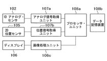
図2は、本実施形態のモバイル装置のブロック図である。本実施形態のモバイル装置は、一次元(1D)アナログ・センサ102、二次元(2D)位置センサ105、ディスプレイ106、アナログ信号取得ユニット107a、位置信号取得ユニット107b、プロセッサ・ユニット108a、データ記憶装置108b、および画像処理ユニット108cを含む。
【0043】
本実施形態において、プロセッサ・ユニット108aは、プロセッサ(CPU)、メモリ、ならびに、情報処理、ディスプレイ106、およびセンサ102、105を制御するための必要なユニット全てを含んでいても良い。本モバイル装置は、更に、他の装置および/またはネットワーク接続と通信を行うための任意の有線または無線の通信ユニットを含んでいても良い。
【0044】
ユーザは、1Dアナログ・センサおよび2D位置センサを用いてモバイル装置を制御しデータを入力する。これらのセンサは、ディスプレイ106の画面を遮ったり干渉したりしない限り、いかなる位置に配置しても良い。
【0045】
また、複数の1Dアナログ・センサを設けて、異なる方向で本モバイル装置の物理的な操作を検出しても良い。例えば、1セットの1Dアナログ・センサを設けて、x軸およびy軸の周りのユーザの曲げ入力をそれぞれ検出するようにしても良い。装置のディスプレイが縦長モードおよび横長モードの両方において使用可能な場合、かかる1Dアナログ・センサ・セットを有することが有利である。ユーザが双方のモードについて同一の曲げジェスチャーを行ったとしても、本装置は、どちらのモードで現在の曲げ入力が行われているかを検出することができる。
【0046】
1Dアナログ・センサは、電圧または抵抗等、測定可能な出力信号の制御パラメータにおけるアナログ的な変化を生成する。すなわち、これらのパラメータ変化は、1Dアナログ・センサに加えられる力の変化に直接対応する。1Dアナログ・センサは、本装置に取り付けられた1つまたはそれ以上の検知デバイスを含む場合がある。検知デバイスは、加えられた力を検出する力検知デバイス、形状変化を検出する曲げ検知デバイス、加えられた圧力を検知する圧力検知デバイス、回転運動を検知する回転検知デバイス、および、1Dアナログ・センサに対して行われた物理的な操作に関連して発生した変化を検出する他の任意の検知デバイスを含んでいても良い。
【0047】
本発明では、検知デバイスは、いずれかの特定の種類に限定されるわけではなく、適切なパラメータを検知可能であれば、静電型、電気機械型、磁気型、光学型、およびこれらの物理特性の組み合わせを利用した様々な種類の検知デバイスを用いることができる。
【0048】
2D位置センサは、ディスプレイ106上に表示されたGUI要素の位置を特定するためのユーザの操作を受けて、位置または位置の変化を示す信号を出力する。2D位置センサ105は、2Dトラッキング・センサ、2Dタッチ・センサ、または2次元の変化を検出可能な他の任意のセンサもしくはセンサ群であっても良い。2D位置センサは、可撓性メッシュ・センサまたは静電容量型を含んでいても良い。
【0049】
センサ102、105によって検出されたユーザの入力は、アナログ信号取得ユニット107aおよび位置信号取得ユニット107bによってそれぞれ取得される。取得ユニット107aおよび107bによって取得されたデータは、処理ユニット108a、データ記憶装置108bに格納された情報、および画像処理ユニット108cを用いて処理され、グラフィカル・ユーザ・インタフェース要素を更新するための画像データ等の対応するグラフィック画像データを生成する。本実施形態のユーザ入力は、従来のオブジェクト指向、イベント駆動プログラミング言語におけるイベントとして解釈することができる。すなわち、あるイベントが検出されると、検出されたイベントに応答してイベント・ハンドラ(プログラム)が起動して、所望のGUI動作を実行する。
【0050】
データ記憶装置に格納された情報は、ディスプレイ106上に表示される画像に対応した様々な画像またはマップ・データ要素を含んでいても良い。以下に、様々なタスクにおいて実行される処理ステップの詳細を述べる。最後に、ディスプレイ106を用いて、更新されたグラフィカル・ユーザ・インタフェース要素の画像がユーザに提示される。
【0051】
あるいは、視覚ディスプレイに加えて、力覚的ディスプレイおよび/または聴覚的ディスプレイ(オーディオ出力)をユーザに提示しても良い。ユーザ入力の力覚的および聴覚的のフィードバックのために力覚的ディスプレイおよび聴覚的ディスプレイを設けても良い。
【0052】
図3(A)〜(D)に、本実施形態のモバイル装置の例を示す。図3(A)および3(B)は、埋め込まれた曲げセンサ102および裏側の可撓性2D位置検知パネル105を有する可撓性ディスプレイ106を含むモバイル装置の構成を表す。図3(A)および3(B)は、それぞれ逆方向に力を加えた場合の本例におけるモバイル装置の2つの形状を示す。
【0053】
本例では、可撓性ディスプレイ106、曲げセンサ102、および可撓性2D位置検知パネル105は、それぞれ、ディスプレイ106、1Dアナログ・センサ102、および2D位置センサ105として機能する。可撓性ディスプレイは、可撓性有機エレクトロルミネッセンスまたは任意の可撓性部材で構成されたディスプレイであっても良い。
【0054】
本モバイル装置とのユーザの相互作用は、以下を含んでいてもよい。
a)装置全体を上下に曲げ、可撓性ディスプレイ106の画面上で、曲げセンサ102が検出した入力の結果を見る。
b)装置全体を上下に曲げる一方で、裏側の2D位置検知パネル105を用いてインタフェース要素の位置を制御する。
c)装置によって認識され、コマンドを発行するために使用することが可能なパターンで装置全体を上下に曲げる。
d)装置をある程度曲げ、その量で装置を曲げ続けるもので、その曲げ量があるパラメータについて変化の速度を特定する。
【0055】
図3(C)および3(D)は、前記構成の1つの代替的な実施を示すもので、この場合、装置自体を曲げることは不可能であるが、ユーザは、装置の一方側または両側に配置された圧力パッド103に力を加える。ユーザの相互作用は、図3(A)および3(B)に示した例のものと同様であり、いずれの場合でも、ユーザは、データの入力および装置の制御をするために、同様の方法で装置に力を加える。
【0056】
(2)定義と使用する用語
(2.1)1Dアナログ・センサからのデータの解釈
本明細書では、1Dアナログ・センサから受け取ったデータを参照するための総称的な方法を用いる。上述のように、1Dアナログ・センサは、センサに与えられたユーザ入力に比例した数値を戻す様々なセンサとすることができる。様々なセンサまたはセンサの組み合わせを使用可能であるが、以下の説明では、1Dアナログ・センサとして、多くの場合、力センサを用いる。
【0057】
更に、本明細書では、1Dアナログ・センサを、アナログ・コントローラまたはアナログ入力デバイスと呼ぶこともある。
【0058】
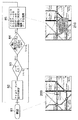
仮に、1Dアナログ・センサNからのアナログ制御変数の測定値が、ある範囲内に分布しており、我々は、例えば−100または+100とすることができるある閾値を設定するものとする。次いで、図4に示すように、センサからのデータを次のように解釈する。
0(例えばヌル):装置の「ニュートラル」な状態(403)、すなわちユーザからの入力は与えられていない。
N=100:ユーザが入力を加えて、センサ値が閾値または目標値に達した。このイベントを「上方目標」と呼ぶ(401)。
N=−100:上と同じであるが、負の閾値に達する点が異なる。このイベントを「下方目標」と呼ぶ(405)。
Nは、0から100まで変化する。ユーザは、アナログ・コントローラを動かして、ニュートラルと正の閾値との間で、例えば正の遷移スペースでその出力値を変化させる。このイベントを「上方遷移」(402)と呼ぶ。
Nは、0から−100まで変化する。上と同じであるが、ユーザが負の遷移スペースでアナログ・コントローラを動かす点が異なる。このイベントを「下方遷移」(404)と呼ぶ。
【0059】
なお、以下のことを注記しておく。a)一部のセンサは、正のスペース領域のみを有する場合がある。例えば、圧力センサは、一方向でのみデータを検知することができる。b)センサの組み合わせを、単一のセンサとして扱うことができる。例えば、2つの圧力センサを組み合わせて、入力の正および負の方向を検出可能とする。ならびに、c)ユーザが加えた力の量のみを検知する1つのセンサと、その力の方向を検出する1つのスイッチを組み合わせる。
【0060】
(2.2)画面上のインタフェース要素およびそれらとの相互作用
本明細書では、選択可能または作用可能な画面上の要素を用いて、本発明の実施形態を説明する。これらは、ユーザとの相互作用が可能なグラフィカル・ユーザ・インタフェース要素である。ほとんどの場合、選択可能インタフェース要素との相互作用は、2つの段階から成る。
【0061】
第1の段階:ユーザが相互作用を希望するインタフェース要素の選択。多くの場合、視覚画面上には同時に多くの選択可能インタフェース要素があり、従って、インタフェースは、ユーザが相互作用したいのはどの要素であるかを指定するツールをユーザに提供しなければならない。一度に制御されるインタフェース要素が1つのみである場合は、選択ページを省くことができる。
【0062】
第2の段階:相互作用。ユーザがインタフェース要素を選択した後、ユーザは選択したインタフェース要素と相互作用することができる。相互作用の種類は様々に異なる可能性があり、インタフェース要素の種類に依存する。場合によっては、相互作用は、ボタンの押圧、リストからロードするファイル名またはウエブ・ページ上で追っていくためのリンクの選択等、適切なアクションを実行するための単なる選択の確認である。他のものは、画面上のグラフィック・インタフェース要素の移動等、より複雑である可能性もある。
【0063】
(3)実施例
以下で、本発明の一態様によるモバイル装置において使用可能なユーザ・インタフェースおよび/またはデータ入力手法の例を説明する。以下の例では、モバイル装置は、図2に示すような構成に加えて、聴覚ディスプレイおよび力覚的ディスプレイを含むと想定されている。一般的なものとするために、以下の例において、1Dアナログ・センサは、いかなる特定の種類にも限定されず、その代わり、ユーザは、ディスプレイ106の視覚画面上で出力を観察しながら、2D位置決めおよび1Dアナログ入力を制御可能であると想定されている。1Dアナログ・センサの種類は想定されないが、1Dセンサは、モバイル装置に対して行われるユーザの曲げ入力の量および方向を検出する。
【0064】
(3.1)統合選択およびデータ・ブラウジング相互作用方法
本例によれば、例えばテキストまたは画像のようなコンテンツの2Dまたは1Dブラウジングと選択とを単一のタスクに統合する相互作用方法が提供される。この相互作用方法では、ユーザは、2D位置センサ105を用いて(例えば装置の裏側のタッチ・スクリーンを用いて)、一次元または二次元でディスプレイ106の画面上のコンテンツをスクロールするだけである。選択可能インタフェース要素は、画面上のそれらの現在の位置に依存して自動的に選択され、画面上の位置とどの要素が選択されるかとの関係は、マッチングアルゴリズムによって規定される。マッチングアルゴリズムについては、以下で詳細に説明する。従って、画面上の選択可能インタフェース要素を選択するために、ユーザは、所望の要素が選択されるように単にコンテンツをスクロールするだけである。
【0065】
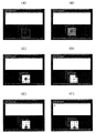
図5は、コンテンツ・ブラウジングによってインタフェース要素を選択するための本例のプロセスを例示するフローチャートおよびスナップショットを示す。図5の右側に、このプロセスの基本ステップを示し、図5の左側に、アプリケーションおよび受信データの画面のスナップショットを示す。
【0066】
ステップ51:ユーザは、ディスプレイ106の画面上で地下鉄地図をブラウジングする。現在選択されている項目は、項目201である。
【0067】
ステップ52:2D位置センサ105を用いて、ユーザは地図を左へ、XおよびYユニット分だけスクロールする。
【0068】
ステップ53:実際の左へのスクロール量は、アプリケーションおよび2D位置センサ105に依存し、通常、いくつかのマッピング機能を用いて変更される(例えば、感度を調整可能である)。従って、実際のスクロール量は、入力デバイス(2D位置センサ105)から受信したデータとコンテンツの実際のスクロール量との間のマッピングであるF(X)およびG(Y)によって計算される。次いで、このコンテンツだけ地図がスクロールされる。
【0069】
ステップ54:次いで、プロセッサ・ユニット108aは、マッチングアルゴリズムを用いて、画面上のコンテンツ位置に対して最も適切な選択可能インタフェース要素を検索する。
【0070】
ステップ55:選択可能インタフェース要素を見つけたら、プロセスはステップ56に進む。見つけなかった場合は、ステップ58に進む。
【0071】
ステップ56:202として示される新たに見つかった選択可能要素を選択する。
【0072】
ステップ57:以前の要素201についての視覚フィードバックを除去し、様々な視覚および力覚的フィードバックを用いて、新たな選択要素202をアクティブ要素として示す。
【0073】
ステップ58:現在選択されている要素がいまだ見えている場合、プロセスはステップ51に進み、そうでない場合、プロセスはステップ59に進む。
【0074】
ステップ59:現在選択されている要素の全ての指示を除去し、視覚インタフェースをヌル構成にリセットする。
【0075】
マッチングアルゴリズムは、画面上の現在のコンテンツ位置に応じて、いくつかの視覚アイテムから、どの選択可能アイテムあるいは作用可能アイテムを選択すべきかを規定する。多種多様なアルゴリズムを用いることができる。例えば、
a)画面の中心に最も近いアイテムを選択する。このマッチングアルゴリズムのもとでアイテムを選択するためには、ユーザはコンテンツをスクロールして、所望のアイテムが画面の中央に来るようにする。
【0076】
b)ユーザのスクロール方向とは逆の方向にあるアイテムを選択する。このマッチングアルゴリズムのもとでアイテムを選択するためには、ユーザはスクロールとは逆の方向にコンテンツをスクロールする。例えば、選択するアイテムを引き寄せる。
【0077】
c)選択するアイテムは、上述のa)およびb)で説明したマッチングアルゴリズムの組み合わせによって、または、ユーザ入力に従って選択すべき単一のアイテムの識別を可能にする他の任意のマッチングアルゴリズムによって識別される。
【0078】
(3.2)アナログ選択入力手法
従来の手法では、マウスまたはキーボード等の物理的な入力デバイスに対してボタンの押圧動作を実行して、ユーザ・インタフェース要素の選択を確認する。かかるボタン押圧動作は、ディスクリートなイベントである。本例では、データの選択を確認し、モバイル装置上でデータと相互作用するいくつかの手法について説明する。モバイル装置は、手持ち式デバイスであって、この手持ち式デバイスに取り付けたアナログ・センサを含み、どんなボタンも用いないものとしてもよい。
【0079】
これらの手法は、主として上述のモバイル装置のためのものであるが、これらの手法は、例えば2Dの位置入力および1Dの力入力の双方を同時に制御可能な、同様の特性を有する他のデバイスにも適用可能である。
【0080】
(3.2.1)単純な確認
図6は、ウエブ・ページ・ナビゲーションのための本例の手法を用いた単純な選択の場合を表し、フローチャートおよびインタフェースの視認状態のスナップショットを含む。スナップショットの左側のバー301は、1Dアナログ・センサの出力値、例えばユーザの曲げ入力の量を示す。
【0081】
ステップ61:画面の現在のインタフェース・ビュー204上のインタフェースの作用可能アイテム(例えばアイテム203)が選択され、1Dアナログ・センサ102がその「ニュートラル」状態にある場合に、本例の手法が開始する。
【0082】
ステップ62:アナログ・コントローラの現在の値、例えば曲げの量を測定する。
【0083】
ステップ63:プロセッサ・ユニット108aは、アナログ・コントローラが図4に示すような目標状態(例えば上方目標または下方目標)に達したか判定する。目標状態に達したら、プロセスはステップ64に進む。そうでない場合、プロセスはステップ62に戻って、1Dアナログ・センサ102からの出力の測定を繰り返す。
【0084】
ステップ64:選択を確認し、新しいビュー205のロード等の適切なアクションを実行する。本例では、次のウエブ・ページのロードを実行する。
【0085】
ステップ65:次のウエブ・ページのため視覚インタフェースを更新し、力覚、視覚、および音声のフィードバックを提供して、このアクションをサポートする。
【0086】
ステップ66:インタフェースがニュートラルな状態に戻るのを待って、ステップ61から継続する。
【0087】
(3.2.2.)選択の2方向確認
2方向確認は、節(3.2.1)で説明した単純な確認と同様に機能するが、「上方目標」および「下方目標」状態を区別し、これらを異なる目的に用いるという点が異なる。例えば、「下方目標」イベントを用いて選択を確認し、一方、「上方目標」を用いて以前の位置に戻ることができる。
【0088】
(3.2.3)統合プレビューおよび選択起動
「上方遷移」および「下方遷移」状態を用いて、ユーザ・インタフェース・ビュー間の円滑な遷移を行うことができる。本インタフェースでは、次のインタフェース要素を選択すると、遷移が即座に行われるが、ニュートラルおよび「上方目標」状態またはニュートラルおよび「下方目標」状態の間の1Dアナログ・センサ102からのアナログ・コントローラの値を用いることによって、異なるユーザ・インタフェース・ビュー間で円滑な視覚的な遷移を設計することができる。本明細書では、この手法を「アナログ・リンク」と呼ぶ。
【0089】
図7は、地図ナビゲーション(図5と同様)のための本手法を用いた選択の場合を表し、フローチャートおよびインタフェースの視認状態を含む。図7は、2つのビューをどのように重ねることができるかを示す。初期ビュー(現在のインタフェース・ビュー207)は地下鉄地図であり、一方、他のビュー(次のインタフェース・ビュー208)は対応する道路地図である。
【0090】
ステップ71:1Dアナログ・センサ102がその「ニュートラル」状態にあり、現在のインタフェース・ビュー207上でインタフェースの作用可能アイテム(例えばアイテム206)が選択された場合に、この手法が開始する。
【0091】
ステップ72:アナログ・コントローラの現在の出力値、例えば曲げ量を側定する。
【0092】
ステップ77:入力がない場合、プロセスはステップ72に戻る。入力がある場合、プロセスはステップ78に進む。
【0093】
ステップ78:現在のインタフェース・ビュー207の上に、次のインタフェース・ビュー208を重ねる。アナログ・コントローラの値が大きくなればなるほど、ユーザ・インタフェースの次のインタフェース・ビューが見えやすくなる。以下の方法のいずれか1つまたは組み合わせを用いて、ビューを重ねることができる。
(a)透過性:次のビューは現在のビューの上に重ねられ、次のビューの透過性が、アナログ・コントローラの値によって制御される。ユーザがアナログ・コントローラに加える入力が増大すると、次のビューの透過性が低くなる。
(b)ズーム:次のビューのサイズは、アナログ・コントローラの値によって制御される。ユーザがアナログ・コントローラに加える入力が増大すると、次のビューが大きくなる。
(c)ズームおよび透過性の組み合わせ。
(d)ユーザが2つのビューを同時に見ることが可能でありながら、2つのビューを全体的または部分的に重ね合わせることができる他の任意の方法。
【0094】
ステップ73:アナログ・コントローラが目標状態(例えば上方目標または下方目標)に達したかチェックする。目標状態に達した場合、プロセスはステップ74に進む。目標状態に達していない場合、ステップ72に戻る。
【0095】
ステップ74:選択を確認し、適切なアクションを実行する。例えば、次のユーザ・インタフェース・ビュー208を完全にロードし、以前のビューは見えない。
【0096】
ステップ75:視覚インタフェースを更新し、力覚、視覚、および音声フィードバックを提供する。
【0097】
ステップ76:アナログ・コントローラがニュートラル状態に戻るのを待って、ステップ71から継続する。
【0098】
(3.3)相互作用による追加情報のプレビューの手法
「上方遷移」および「下方遷移」状態を用いて、作用可能アイテムに関連する情報をユーザに提供することができる。添付する情報の例は、リンク内のコンテンツのプレビュー、添付されたヘルプ情報、ユーザが添付した注記等とすることができる。ユーザがセンサに入力を加えると、「上方遷移」または「下方遷移」状態によって、リンク上の関連情報をユーザに提供する。追加情報の特性は、アナログ・リンクによって制御することができ、以下を含んでいても良い。
a)透過性。
b)大きさ。
c)詳細の情報レベル。例えば、ユーザがアナログ・コントローラに加える入力が増大すると、より多くの情報を提示する。
d)上述の、または他の任意の適用可能な特性の組み合わせ。
【0099】
図8は、本例の手法を用いて作用可能アイテムに添付された注記データをプレビューする場合の、本例によるプロセスのフローチャートおよびプロセスに関連するスナップショットを表す。
【0100】
ステップ81:1Dアナログ・センサがその「ニュートラル」状態にあり、画面上に表示された現在のインタフェース・ビュー上で、インタフェースの作用可能アイテム(例えばアイテム209)が選択された場合に、このプロセスが開始する。
【0101】
ステップ82:アナログ・コントローラの現在の出力値、例えば曲げ量を測定する。
【0102】
ステップ83:入力がない場合、プロセスはステップ82に戻る。入力がある場合、ステップ84に進む。
【0103】
ステップ84:何らかの視認可能データが添付されている場合、プロセスはステップ85に進む。データがない場合、ステップ82に戻る。
【0104】
ステップ85:添付データ210を現在のビューの上に重ねる。アナログ・コントローラの出力値が大きくなると、この添付データの視認性が高くなる。視認性の制御パラメータは、以下を含んでいてもよい。
a)透過性:データは現在のページの上に重ねられ、その透過性が、アナログ・コントローラの出力値によって制御される。ユーザが1Dアナログ・センサに加える入力が増大すると、追加データの透過性が低くなる。
b)ズーム:サイズは、アナログ・コントローラの出力値によって制御される装置に添付された追加情報のものである。ユーザが1Dアナログ・センサに加える入力が増大すると、追加データのサイズが大きくなる。
(c)ズームおよび透過性の組み合わせ。
(d)ユーザが2つのビューを同時に見ることを可能にし、ユーザが2つのビューを重ね合わせることができる任意の他の方法。
【0105】
(3.4)ズームおよび視点制御のための相互作用手法
本例において、GUI相互作用方法は、画面上に提示された視覚情報の拡大および縮小を可能とすると同時に、視点位置を変化させることができる。画像は、「上方遷移」状態で拡大され、「下方遷移」状態で縮小される。アナログ・コントローラの出力値は、ズームの速度または量にマッピングされる。位置制御は、1Dアナログ・センサを介したアナログ入力とは独立して、2D位置センサの使用によって達成可能であるので、ユーザは、同じ単一のジェスチャーによって、同時にズームと視点位置の制御とをすることができる。
【0106】
(3.5)三次元ナビゲーション手法
上述の例(3.4)において説明した手法は、画面における3Dナビゲーションに用いることができる。ズームインにより内側に飛ぶ結果となり、一方で、方向制御が飛行方向の制御を可能にする。
【0107】
図9は、本実施形態によるモバイル装置を用いた3Dナビゲーションのためのインタフェース手法について、本例によるプロセスのフローチャートおよびプロセスの関連するスナップショットを表す。
【0108】
ステップ91:1Dアナログ・センサ102がニュートラル状態にあり、ディスプレイ106の画面上に3D環境が提示された場合に、このプロセスは開始する。
【0109】
ステップ92:2D位置センサ105の現在の出力値を測定する。
【0110】
ステップ97:入力がない場合、プロセスはステップ92に進む。入力がある場合、ステップ93に進む。
【0111】
ステップ93:2D位置センサから出力された二次元座標データを用いて、動き211の方向を規定するベクトルVの3D方向を更新する。ベクトルは、ユーザに提示して視覚フィードバックをユーザに提供するか、または隠しても良い。
【0112】
ステップ94:アナログ・コントローラの現在の出力値を測定する。
【0113】
ステップ98:入力がない場合、プロセスはステップ92に進む。入力がある場合、ステップ95に進む。
【0114】
ステップ95:アナログ・コントローラの測定値を用いて、ベクトルVに沿った平行移動Dの量を計算する。線形マッピング、非線形マッピング、および他のいずれか等、様々なマッピングを規定しても良い。
【0115】
ステップ96:量DだけベクトルVの方向に視点を平行移動させ、ステップ92から継続する。
【0116】
視点位置およびコントローラのパラメータに応じて、様々な種類のアプリケーションで、この3Dナビゲーション・アルゴリズムの変形を実施することができる。
【0117】
上述の例では、2D位置センサ105を用いて2D位置入力を提供している。あるいは、2D位置入力を用いて1Dまたは2D方向のいずれかで画面ビューをスクロールする場合には、2D位置センサ105を、ユーザの入力に従ってスクロールを制御可能とする任意の他の種類のデバイスで置換しても良い。例えば、加速度計を含む傾斜センサを用いて、装置の傾斜を検出し、ユーザが装置をある方向および量に傾斜させることによってスクロールの速度および方向を制御するようにすることも可能である。
【0118】
(3.6)力覚的フィードバック
上述の例は、力覚的フィードバック装置を用いて当該装置の現在の状態をユーザに伝えるように拡張しても良い。例えば、力覚的フィードバックは、多層構成の圧電アクチュエータを利用することによって実現しても良い。
【0119】
本実施形態によれば、ユーザは、マウス、タッチ・パネルおよび/またはキーボードを用いることなく、モバイル装置または小型の手持ち式デバイスと相互作用することができる。装置のディスプレイ画面の裏側にタッチ・パネルが配置されている場合、ユーザの装置との相互作用は、画面を遮ることがなく、これによって相互作用が容易になる。相互作用は簡単になり、より効果的になり、より直観的に、楽しいものとなる。
【0120】
更に、本実施形態によれば、GUI要素との相互作用手法によって、可撓性コンピュータおよび多くの新しい相互作用デバイスと共に使用可能なインタフェースの、簡単かつ基本的な設計方法を提供することができる。この手法によって、手持ち式コンピュータによる基本的な相互作用タスクのほとんどに対応することができる。
【0121】
本実施形態による手法の利点は、この手法が、装置の簡単な物理的操作によって多くの相互作用タスクを実行する単一の統合された方法であることである。これによって、インタフェースはより簡単に、より直観的に用いられるようになる。ユーザはいくつかの簡単な動作の使用方法を覚えておかなければならないだけであり、これがタスクを行うために必要な全てである。
【0122】
本実施形態では、タスクを実行したり、アプリケーション・プログラムと相互作用したりするために、画面上に追加のグラフィカル・ユーザ・インタフェース要素は必要ない。従って、これは、画面上のスペースを節約し、表示領域の効率的な使用を促進する。かかる特徴は、比較的小さい表示領域を有する手持ち式デバイスには特に重要である。
【0123】
本実施形態による手法は、多くのタスクを自動化することができ、小型の手持ち式デバイスではマウスまたはペンまたは他のポインティング・デバイスによる正確な相互作用のためのポインティングが難しい従来の手法に比べて、モバイル状況での装置の使用が容易になる。
【0124】
本実施形態による手法は、より自然であり、使用が容易であり、ペン等の追加の入力デバイスを必要としない。従って、この手法は、当然、ディスプレイの裏側にタッチ・パネルが配置されたデバイスに適している。
【0125】
[第2の実施形態]
(1)システム構成および構成要素
以下に、本発明の第2の実施形態を詳細に説明する。第2の実施形態は、図2および図3に示すような第1の実施形態で説明したタイプの装置について、一般的なGUIの状況でのテキスト入力および/または多次元メニュー方式のための手法に関する。本実施形態の以下の説明では、第1の実施形態と異なるシステム構成の部分のみを説明する。
【0126】
第1の実施形態の図4に示すような1Dアナログ入力データの解釈について、同じ定義および用語を用いる。1Dアナログ・センサ102に必要である重要な特性の1つは、ユーザから何も入力が与えられていない場合、それ自身でニュートラルな状態に戻るということである。
【0127】
本実施形態は、日本国特許出願(公開)H10−154033号およびH10−154144号に開示されたセンテンス入力装置等、様々な装置におけるテキスト入力に適用可能である。具体的には、本実施形態によるテキスト入力手法は、ディスプレイ画面上に表示された候補アイテム群からアイテムの1つを選択するのに有用であり得る。
【0128】
本実施形態では、2D位置センサ105からのデータを以下のように解釈する。図10(A)〜(C)は、2D位置データをどのように用いて(カーソルを用いるように)位置でなく方向を測定することができるかの一例を表す。図10(A)は、選択のためのアイテム格子の一例を示し、図10(B)は、方向区分の一例を示し、図10(C)は、方向区分とアイテムとの間の関係の一例を示す。本例の実施態様では、選択が格子から行われる場合はいつでも、このアプローチが取られる。このアプローチの利点は、アクションが反復可能となることである。
【0129】
図10(A)に示すアイテムの3×3格子では、デフォルトにより中央のアイテム(図中、数字5)が選択される。これが所望のアイテムである場合、ユーザはこのデフォルト選択を確認するだけで良い。中央の周りのアイテムのうち1つが所望である場合、上述の2D位置センサ105を用いた「方向移動」によって選択を行うことができる。次いで、(以下に与える例において45度の)角度区分のアレイに関連付けた方向移動が測定される。例えば、左下への移動は、2D位置センサ上のユーザの指の位置とは無関係に、左下のアイテム(この例では数字7)を選択することになる。右上への動きは、この例では数字3を選択し、右への動きは数字6に関連する、等である。
【0130】
(2)インタフェース手法の詳細
(2.1)相互作用フロー
本実施形態によるGUI制御手法は、上述の入力デバイス(1Dアナログ・センサおよび2D位置センサ)との組み合わせで動作する。以下で、GUI制御手法の3つの変形について説明する。一例としてテキスト入力を用いる。しかしながら、本発明はこれらの変形に限定されるわけではなく、本実施形態は、アイテムがテキスト文字でなくメニュー・アイテムから成る他の変形にも同様に適用可能である。
【0131】
図11に、相互作用の基本フローを示す。GUI制御手法の全ての変形は、以下の相互作用ステップを共有し、ここで、ステップ群a)およびb)は同時に行うことができる。
a)多次元アレイにおけるアイテム群の選択(ステップ112〜114)。
b)選択した群内での1つのアイテムの選択(ステップ115〜116)。
c)現在の群/アイテム選択の確認または取り消し(ステップ117/ステップ118)。
【0132】
図11に示す相互作用ステップは、電話のキーパッドの使用と比較することができる。キーパッドでは、ユーザは、最初に、文字群を表すボタンを選択し(すなわち「A」、「B」、「C」等にアクセスするために「2」)、次いで、意図するアイテム(すなわち文字)に達するまでそのボタンを繰り返し押す。GUI制御手法がこのテキスト入力と異なる点は、ボタンの代わりに2D位置検知と組み合わせた1Dアナログ入力を用いることである。
【0133】
本例の実施態様は、ユーザがアイテム群を選択する方法が異なる。全ての例は、1Dアナログ入力および2D位置入力を組み合わせて用いることを利用している。
【0134】
(2.2)循環層を用いた例示的な実施態様
図12および13(A)〜(D)は、本例によるプロセスのフローチャート、および、このプロセスと関連してディスプレイ106の視覚画面上に表示されるスナップショットを示す。スナップショットの各々は、画面ビュー1300を示し、ここでは、入力されたテキストを示すウインドウ1301および積み重ねた層1302が提示されている。
【0135】
本例は、各々がアイテム群を示す視覚的な複数層のシステムを用いる。積み重ねの「最上部」に、現在選択されている層1302bがある。ユーザは、1Dアナログ入力デバイスとして機能する1Dアナログ・センサ102を操作することで、これらの層を循環させる。図13(A)は、ステップ1201における開始状態のスナップショットである。
【0136】
・群選択(ステップ1202〜1209)
図13(B)は、群選択中のスナップショットである。ステップ1202において、1Dアナログ入力を測定し、ステップ1203〜1205において、アナログ入力が「上」もしくは「下」方向、または「ニュートラル」状態にあるかについて、測定した入力を調べる。1Dアナログ入力が「下」状態にある場合、プロセスはステップ1209に進み、現在の群選択を更新する。「上」または「ニュートラル」状態にある場合、それぞれステップ1207またはステップ1208に進む。アナログ入力「下方遷移」データは、アプリケーションがこれらの層を循環する速度に対応付けられる。入力データが「目標下方」状態に近づくと、層循環の速度が増す。入力デバイスが「ニュートラル」状態になると、循環は停止する。
【0137】
・アイテム選択(ステップ1211)
図13(C)は、アイテム選択中のスナップショットである。この例では、図13(B)に示すように、アイテムは3×3の格子に配列されている。新たな群が選択されるたびに、その中央のアイテムをデフォルトで選択する。他のアイテムは、2D位置センサを用いた方向入力により選択し(ステップ1211)、更新した現在のアイテム選択を提示する(ステップ1212)。
【0138】
・選択の確認または取り消し(ステップ1210)
図13(D)は、選択の確認中のスナップショットである。いったん所望の群およびアイテムを選択したなら(ステップ1207でイエス)、ユーザは「上方遷移」によって選択を確認する(ステップ1210)。選択を行わない場合には、「完了」層を選択して、選択モードから出なければならない。
【0139】
(2.3)「ラチェット」層を用いた例示的な実施態様
図14および15(A)〜(F)は、この例によるプロセスのフローチャート、および、このプロセスに関連してディスプレイ106の視覚画面上に表示されるスナップショットを示す。図12および13(A)〜(D)の先の例におけると同様に、この例も、各々がアイテム群を表す視覚的な複数層のシステムを用いる。積み重ねの「最上部」に、現在選択されている層がある。ユーザは、1Dアナログ入力デバイスを操作することで層を選択する。図15(A)は、開始状態のスナップショットである(ステップ1401)。
【0140】
・群の選択(ステップ1402〜1409)
図15(B)は、群の選択中のスナップショットである。アナログ入力の「下方遷移」データを、積み重ねた層の深さにマッピングする。例えば、4層の群の積み重ねおよび0(「ニュートラル」)から−5(「下方目標」)の範囲に及ぶ入力データでは、「下方遷移」データは、以下のようにマッピングすることができる。
0から−0.5 選択なし
−0.5から−1.5 群1
−1.5から−2.5 群2
−2.5から−3.5 群3
−3.5から−4.5 群4
−4.5から−5 群選択の取り消し(ステップ1413)
1Dアナログ入力デバイスが「ニュートラル」位置に戻ると、群選択が「下方目標」によって取り消されるまで(ステップ1413)、または現在の選択が確認されるまで(ステップ1411)、「最も深い」群が選択されたままである。図15(C)は、「ニュートラル」状態によってデフォルト選択が行われているステップ1408におけるスナップショットである。
【0141】
・アイテム選択(ステップ1412〜1414)
図15(D)および15(E)は、アイテム選択中のスナップショットである。図に示すように、アイテムは3×3の格子に配列されている。新たな群が選択されるたびに、その中央のアイテムをデフォルトで選択する。他のアイテムは、上述のように、2D位置センサ105によって方向入力を用いて選択する。群の選択およびアイテムの選択は、同時に行うことも可能である。
【0142】
・選択の確認または取り消し(ステップ1406、1411、1413)
図15(F)は、選択の確認中のスナップショットである。いったん所望の群およびアイテムを選択したなら、ユーザは「上方遷移」状態によって選択を確認する。群の選択は、「下方目標」状態によって取り消すことができ、選択モードからは、「上方目標」状態によって出ることができる。
【0143】
(2.4)ネスト化された格子を用いた例示的な実施態様
図16および17(A)〜(F)は、本例によるプロセスのフローチャート、および、このプロセスに関連してディスプレイ106の視覚画面上に表示されるスナップショットを示す。先の例では、1Dアナログ入力データを、群選択の直接的な手段として用いる。本例では、1Dアナログ入力データを、群選択とアイテム選択との間のモード・スイッチとして用いる一方、2D位置センサを用いた方向入力を、群選択およびアイテム選択の双方に用いる。視覚的には、このシステムは3×3の格子の群として表され、各格子は、図17(B)に示すように、9(3×3)までのアイテムを含む。図17(A)は、ニュートラルな状態を示し、ここからプロセスが開始する(ステップ1601)。
【0144】
・群選択(ステップ1602〜1613)
図17(B)および17(C)は、群の選択中のスナップショットである。1Dアナログ入力デバイス102によって検出された1Dアナログ入力の「下方遷移」状態が、この群選択モードをトリガし、このモードで、ネスト化された格子1701から群の1つを選択することができる。デフォルトにより中央の群が選択される。1Dアナログ入力デバイス102が「下方遷移」状態である間に(ステプ1605)、2D位置センサ105が検出した方向入力を用いて群を選択する(ステップ1610、1609、1613)。群選択は、「下方目標」状態によって取り消すことができる(ステップ1604)。
【0145】
・アイテム選択(ステップ1612、1615)
図17(D)および17(E)は、アイテム選択中のスナップショットである。1Dアナログ入力デバイスが「ニュートラル」位置にある間、方向入力を用いてアイテムを選択する(ステップ1612、1615)。デフォルトにより中央のアイテムが選択される。アイテム選択は、先の例におけるものと同じアルゴリズムを用いて実行することができる。
【0146】
・選択の確認および取り消し(ステップ1606、1611、1614)
図17(F)は、選択の確認および取り消し中のスナップショットである。群およびアイテムを選択すると、この選択は、1Dアナログ入力の「上方遷移」状態によって確認される(ステップ1611)。いかなる選択も、「下方目標」状態によって取り消され(ステップ1614)、選択モードからは、「上方目標」状態によって出る(ステップ1606)。
【0147】
上述の本実施形態の例では、2D位置センサ105を用いて方向入力を入力し、選択された群のアイテムのうち1つまたは群の集合から群のうち1つを選択する。しかしながら、本発明はこれらの例に限定されるわけではなく、任意の他のデバイスが、画面上に表示される選択された群のアイテムのうち1つを選択するためのユーザ入力を検出可能であれば、2D位置センサ105の代わりに、かかるデバイスを用いることも可能である。例えば、傾斜センサおよびその視覚フィードバックを利用して、方向入力、すなわち、アイテム選択のための視覚画面の中央位置に対する方向に関するユーザ入力を判定しても良い。
【0148】
上述の本実施形態によるGUI方法によって、ユーザは、マウス、タッチ・パネルおよび/またはキーボードを用いることなく、小型の手持ち式装置と相互作用することができる。2D位置センサは装置の裏側に配置されているので、装置とのユーザの相互作用は視覚画面を遮ることがなく、これによって、装置の動作中ずっと画面の最大の視認性を維持することが容易となる。
【0149】
上述のGUI方法は、1Dアナログ・デバイスおよび2D位置検知入力デバイスの組み合わせに基づいた、より広いGUI環境の一部である。このより広い環境においてGUI方法を用い、以下の機能性を提供することができる。
【0150】
a)テキスト入力
本実施形態によって、ボタンまたはペンを用いることなくテキスト入力が可能となる。本実施形態によれば、GUI手段を装置に提供し、アナログ入力および方向入力を用いて、モバイル状況において、より簡便にテキストまたは文字を入力する。
【0151】
b)メニュー・スタイル
本実施形態によって、カーソルに基づいたポイント・アンド・クリックの相互作用を用いない環境でメニュー方式を提供することができる。本例がテキスト入力を用いて本実施形態によるGUI方法を実現する場合、文字オプションの変わりにメニュー・アイテムを想定することが容易である。これらのメニューは、デスクトップのGUIメニューとほぼ同じように機能する。すなわち、それらは、コンテンツに関連したアイテム(ブックマーク、TVチャネル等)と同様、システム機能に関連したアイテム(「保存」、「閉じる」等)を含んでいてもよい。
【0152】
上述の第1および第2の実施形態を用いて、マウス、視覚スクリード上に配置されたタッチ・スクリーン、またはキーボードを用いることなく、小型の手持ち式デバイスまたは装置と相互作用することができる。
【0153】
かかるデバイスおよび装置の例には、以下のものを含んでいても良い。
・ディスプレイ画面を有するリモート・コントロール
・テレビ受像機のためのリモート・コントロール。
・PDAおよび個人情報ブラウザ/仕切り。
・移動電話。
・電子ブック。
・手持ち式ゲーム・デバイス。
・GPSを用いたパーソナル・ナビゲーション・デバイス。
・テレビ受像機の遠隔表示ユニット。
【0154】
更に、本発明は、ビデオ画像のナビゲーションのための装置に適用することができる。例えば、「ニュートラル」状態のアナログ・センサによって、通常の速度でビデオを再生する。上および下に曲げることを組み入れて、ビデオ再生の速度を制御することができる。具体的には、アナログ・センサを上に曲げている場合はビデオ再生および/または巻き戻し動作を低速化させ、アナログ・センサを下に曲げている場合はビデオ再生および/または巻き戻し動作を高速化するように制御を構成することができる。あるいは、アナログ出力による制御は、音声の再生および/または巻き戻しを含むことも可能である。
【0155】
本日本出願の最初の請求項または最初の説明には、日本特許法の第39条のもとで発明の単一性の要件に従うように、本発明の様々な態様について、ユーザ・インタフェースのためのアナログ・センサとしての可撓性部分の利用に主に焦点を当てた適用に関して記載がされている。しかしながら、発明者は、本明細書に開示された主題には、全体としてまたは部分として、他にも発明的な特徴があると考える。このような発明的特徴に関して特許権を放棄することや、このような発明的特徴を様々な補正、分割、または継続出願等の請求項の主題として再取得する権利を放棄することは、本発明者の意図するところではない。
【0156】
【発明の効果】
本発明の一態様によれば、ユーザが、装置の筐体を物理的に操作することによって装置と相互作用し、ボタン、ペン、または他の任意の機械的コントローラを用いることなく、広範囲のタスクを実行することができるようにするための装置へのデータ入力およびインタフェース手段が提供される。
【0157】
本発明の他の態様によれば、様々なタスクを実行させ、テキストの入力やメニュー/リストから選択を行うよう装置へ指示をするために、位置入力およびアナログ入力を利用する装置へのデータ入力および相互作用手段が提供される。
【図面の簡単な説明】
【図1】図1(A):画面上でGUI要素を選択するための従来のGUI制御手法を示す図である。
図1(B):情報をブラウジング/スクロールするための従来のGUI制御手法を示す図である。
【図2】本発明の一実施形態による装置のブロック図である。
【図3】図3(A):可撓性ディスプレイ・デバイス、曲げセンサ、および裏側の可撓性追跡面を有する、図2に示した装置の斜視図である。
図3(B):可撓性ディスプレイを有する、図2に示した装置の別の斜視図である。
図3(C):非可撓性モニタおよび一対の圧力センサを有する、図2に示した装置の斜視図である。
図3(D):非可撓性モニタを有する、図2に示した装置の別の斜視図である。
【図4】1Dアナログ・センサの状態およびその状態を説明するための対応する用語を示す図である。
【図5】コンテンツ・ブラウジングによってGUI要素を選択するためのアルゴリズムのフローチャート、および、このアルゴリズムのステップでの視覚画面のスナップショットを含む図である。
【図6】1Dアナログ・センサを用いてリンクを選択するためのアルゴリズムのフローチャート、および、例示的なウエブ・ブラウザのアプリケーションについてのアルゴリズムのステップでの視覚画面のスナップショットを含む図である。
【図7】アナログ・コントローラを用いたユーザ・インタフェース・ビュー間の円滑な遷移が行われるアナログ・リンクのためのアルゴリズムのフローチャート、および、このアルゴリズムのステップでの視覚画面のスナップショットを含む図である。
【図8】作用可能アイテムに添付されたデータをプレビューするためのアルゴリズムのフローチャート、および、このアルゴリズムのステップでの視覚画面のスナップショットを含む図である。
【図9】3Dナビゲーション動作を実行するためのアルゴリズムのフローチャート、および、このアルゴリズムのステップでの視覚画面のスナップショットを含む図である。
【図10】図10(A):選択のために2D位置センサによって検出された方向入力と共に用いる例示的なアイテム格子を示す図である。
図10(B):方向入力を検出するために用いる例示的な方向区分を示す図である。
図10(C):図10(A)および10(B)に示す方向区分とアイテム格子との間の関係を示す図である。
【図11】本発明の第2の実施形態における基本的な相互作用フローのフローチャートである。
【図12】第2の実施形態による循環群を用いた例示的な実施態様のフローチャートである。
【図13】図13(A):図12の例のフローの開始状態における視覚画面のスナップショットを示す図である。
図13(B):図12の例のフローにおける群選択中の視覚画面の別のスナップショットを示す図である。
図13(C):図12の例のフローチャートにおけるアイテム選択中の視覚画面の別のスナップショットを示す図である。
図13(D):図12の例のフローにおけるアイテム確認中の視覚画面の別のスナップショットを示す図である。
【図14】第2の実施形態によるラチェット層を用いた例示的な実施態様のフローチャートである。
【図15】図15(A):図14の例のフローのニュートラル状態における視覚画面のスナップショットを示す図である。
図15(B):図14の例のフローにおける群選択中の視覚画面の別のスナップショットを示す図である。
図15(C):図14の例のフローにおけるデフォルト選択によるニュートラル状態での視覚画面の別のスナップショットを示す図である。
図15(D):図14の例のフローにおけるアイテム選択中の視覚画面の別のスナップショットを示す図である。
図15(E):図14の例のフローチャートにおけるアイテム選択中の視覚画面の別のスナップショットである。
図15(F):図14の例のフローチャートにおけるアイテム確認中の視覚画面の別のスナップショットである。
【図16】第2の実施形態によるネスト化された格子を用いた例示的な実施態様のフローチャートである。
【図17】図17(A):図16の例のフローのニュートラル状態における視覚画面のスナップショットを示す図である。
図17(B):図16の例のフローにおける群選択中(デフォルト選択)の視覚画面の別のスナップショットを示す図である。
図17(C):図16の例のフローにおける群選択中の視覚画面の別のスナップショットを示す図である。
図17(D):図16の例のフローにおけるアイテム選択中(デフォルト選択)の視覚画面の別のスナップショットを示す図である。
図17(E):図16の例のフローにおけるアイテム選択中の視覚画面の別のスナップショットである。
図17(F):図16の例のフローにおけるアイテム確認中の視覚画面の別のスナップショットである。
【符号の説明】
102:1Dアナログ・センサ、105:2D位置センサ、106:ディスプレイ、107a:アナログ信号取得ユニット、107b:位置信号取得ユニット、108a:プロセッサ・ユニット、108b:データ記憶装置、108c:画像処理ユニット。[0001]
BACKGROUND OF THE INVENTION
The present invention relates to a user interface device and a mobile information device using such a user interface device. More specifically, the present invention relates to a data input method and an interface method suitable for a mobile device, that is, a device having neither a keyboard nor a mouse.
[0002]
[Prior art]
A major problem with new mobile and handheld devices is that it is difficult to interact efficiently with the device. The input capabilities of mobile devices are typically limited to pen input and touch screen, buttons and jog dial type controllers.
[0003]
The problem with these input methods is that touch screens that block the screen often require the use of a pen, but the use of the pen is often difficult due to the limited resolution of the touch sensor. That is. Also, interaction with the touch screen facilitates an interaction type based on direct sequential manipulation of GUI interface objects. For example, in order to enlarge the map, the user must sequentially repeat scrolling, positioning, and enlargement operations.
[0004]
Alternative devices have been proposed to help create a small but easy to use mobile device. For example, Japanese patent applications JP11-143606 and JP07-64754 disclose devices that accept a user's physical interaction with the device housing. Physical interaction includes changing the shape of the deformable part or tilting the device.
[0005]
Although such devices have been proposed, few attempts have been made to develop graphical user interfaces that utilize these devices. Little research has been done on how such interfaces are useful in basic interface tasks such as data scrolling, navigation, and browsing.
[0006]
Conventional data entry and user interface techniques currently used by most portable devices have been replicated from desktop graphical user interfaces or have been born from attempts to extend them. An example of a conventional data input and interface technique is disclosed in Japanese Patent Application JP2000-207088. These approaches are usually based on the use of a pen and mouse and are generally not suitable for small handheld devices such as mobile or portable devices.
[0007]
For example, traditional interactions with GUI interfaces such as those used in desktop computers and PDAs are based on the concept of a cursor or pointer. The cursor and pointer represent the current position on the display screen as a graphic. For example, to change the current position in order to select a different actionable icon, the user can use an input device such as a mouse or keyboard as shown in FIG. One of these must be specified directly. In this specification, such a task is called pointing or selection.
[0008]
In some cases, the desired element may not be visible on the screen, requiring the user to scroll through the content to find it. Such scrolling of content is a separate task from the above-described pointing (selection). Scrolling usually requires one of the following:
[0009]
a) special user interface elements such as scroll bars, or
b) Interface mode switching. For example, in the current GUI, content begins to scroll down when the cursor reaches the limit of the visible region of the content. Typically, in the conventional interface method, as shown by the
[0010]
These pointing (selection) and scrolling methods are particularly inefficient and difficult to use in devices with a small display screen.
[0011]
[Problems to be solved by the invention]
There are several attempts to study new types of interfaces and data entry techniques suitable for mobile devices. However, most of these studies involve 3D data control (Balakrishnan, R., Fitzmaurice, G., Kurtenbach, G., Sing, K., “Exploring interactive curve and surface manipulation using a bend and twist sensitive input strip. And interactive curve and surface manipulation using torsion-sensitive input strips) ", Proceedings of Symposium on Interactive 3D graphics, 1999, ACM. 111-118), or data scrolling (Rekimoto, J., “Tilting operations for small screen interfaces”, Proceedings of UIST '96. 1996, ACM. Pp. 167-168), or others (Fishkin, K. et al., “Embodied user interfaces for really direct manipulation ", Communications of the ACM, 2000, 43 ( ), 74-80 pages), and the like, have focused on a single task.
[0012]
Furthermore, text input using conventional mobile devices or handheld devices is quite problematic in the following respects. That is, the input functions of mobile devices are typically limited to pen input and touch screen, buttons and jog dial type controllers. There are currently three widely used methods for text input. That is, a system based on gestures such as a keyboard (on the screen or as a physical array of buttons), numeric pad input on a mobile phone, and Graffiti (trade name) from Palm Computing. Among these, the text input method using a numeric pad is probably the most widely used. However, such an approach has several drawbacks. This is because the button has to be pressed many times to enter each character.
[0013]
As the device size decreases, all of the conventional approaches described above become more difficult to use. The need for physical buttons limits the miniaturization of portable computing devices. The touch screen has a limited detection resolution, and there is a possibility that the user may block the screen during an input operation, so there are many problems in a small device.
[0014]
Furthermore, existing computer input devices such as a mouse and pen interface can perform various input operations such as pressing a button on a mouse or pressing a pen on a tablet. However, an external input device is required, which can be a problem for very small devices.
[0015]
The present invention has been made in view of the above-described conventional user interface and data input technique. Providing a data input and interface means for a device that interacts with the device by a user physically operating the housing of the device, and / or a visual display and a device including such data input and interface means desirable.
[0016]
In addition, graphic user interface means that allow a user to perform a wide range of tasks without using buttons, pens, or any other mechanical controller, and / or visual display and such graphic user It would be desirable to provide an apparatus that includes interface means.
[0017]
In addition, it is desirable to provide a data input and interaction means for a device that includes a two-dimensional position sensor and a one-dimensional analog sensor to detect user actions that command the device to perform tasks. In this specification, a task refers to a specific operation mode such as scrolling of an image displayed on a screen and selection of a part of the displayed image.
[0018]
In addition, it is desirable to provide a graphical user interface means for a device that includes a two-dimensional position sensor and a one-dimensional analog sensor for inputting text or selecting from a menu / list.
[0019]
[Means for solving problems]
An information processing apparatus according to the present invention includes a display for displaying information, and pressures from a plurality of directions applied to the information processing apparatus, and based on the pressures, the surface of the display applied to the information processing apparatus An analog sensor for detecting the direction and amount of pressurization in the normal direction, and based on the direction and amount of pressurization detected by the analog sensor , Information on the display As at least one of the transparency and size of the second view displayed above the first view as In response to the amount of pressurization, and the amount of pressurization detected by the analog sensor is equal to or greater than a predetermined threshold value. The display of the display is changed so that the display of the first view and the second view are relatively changed. At the same time, it has a control unit that controls not to make a change corresponding to the amount of pressurization until the amount of pressurization becomes zero.
The information processing apparatus according to the present invention may further include a two-dimensional position sensor for detecting at least one of a position touched by the user with respect to the information processing apparatus and a moving direction of the position touched by the user. it can. The predetermined display may be determined based on the position or direction detected by the two-dimensional position sensor.
The display may be constituted by a flexible display panel, and the two-dimensional position sensor may be disposed on the back surface of the display panel.
A vibration generating unit that generates vibration when the amount of pressurization exceeds a predetermined threshold can be further provided.
The information processing method according to the present invention includes a display for displaying information, and pressures from a plurality of directions applied to the information processing apparatus, and based on the pressures, the surface of the display applied to the information processing apparatus In an information processing method of an information processing apparatus having an analog sensor for detecting the direction and amount of pressurization in the normal direction, based on the direction and amount of pressure detected by the analog sensor , Information on the display As at least one of the transparency and size of the second view displayed above the first view as In response to the amount of pressurization, and the amount of pressurization detected by the analog sensor is equal to or greater than a predetermined threshold value. The display of the display is changed so that the display of the first view and the second view are relatively changed. At the same time, it includes a step of controlling not to make a change corresponding to the amount of pressurization until the amount of pressurization becomes zero.
In the information processing apparatus and method of the present invention, based on the direction and amount of pressurization detected by the analog sensor , Display information As at least one of the transparency and size of the second view displayed above the first view as In response to the amount of pressurization, and the amount of pressurization detected by the analog sensor exceeds a predetermined threshold value. The display of the display is changed so that the display of the first view and the second view are relatively changed. At the same time, control is performed so that no change corresponding to the amount of pressurization is performed until the amount of pressurization becomes zero.
In accordance with one embodiment of the present invention, a user interface device having a flexible portion is provided. The user interface device includes an analog sensor for detecting deformation of the flexible portion, and one of a plurality of first type input states based on the deformation detected by the analog sensor. And a means for executing the task, wherein the task is related to the selected first type input state, and each of the plurality of first type input states is the possible state. Associated with different deformation states of the flexible part.
In this embodiment, at least one of the plurality of first type input states is associated with one of dynamic and static positive deformations of the flexible portion, At least one of the first type input states is associated with one of the dynamic and static negative deformations of the flexible portion.
[0020]
In this embodiment, one of the plurality of first type input states can be associated with a neutral state of the flexible portion in which no deformation is detected. Preferably, at least one of the tasks is for controlling a graphical user interface object.
[0021]
The user interface device according to the present embodiment further includes a two-dimensional position sensor for detecting at least one of a position touched by a user in a two-dimensional plane and a direction of movement of the position touched by the user. Means for detecting a second type of input state related to a position touched by a user detected by the dimension position sensor and executing the task, the task being related to the selected second type of input state is doing. Further, at least one of the first type input states is preferably a transition state corresponding to a task that performs analog control of a graphical user interface object.
[0022]
The user interface device is configured as a single housing electronic device including a flexible display panel as the flexible portion, and the two-dimensional position sensor is located on the back side of the flexible display panel. It is preferable that they are arranged. Preferably, at least one of the tasks related to the second type of input state is for controlling at least one of the movement direction and position of the graphical user interface object. Alternatively, the aforementioned tasks associated with the second type of input state may be any of the shapes of a graphical user interface object or any other graphical object associated therewith, such as scaling, rotation, projection, etc. It is also possible to control the geometric transformation.
[0023]
According to another embodiment of the present invention, there is provided an apparatus configured to have a single housing including a processing unit and a display unit. The device includes an analog sensor disposed on the housing for detecting a user's analog input provided to the housing of the device. The processing unit changes a screen view displayed on the display unit based on an output value of the analog sensor.
[0024]
In the present embodiment, the screen view to be changed includes an image superimposed on an existing view, and the processing unit includes a visual characteristic of the image to be superimposed according to an output value of the analog sensor. One may be changed. Alternatively, the screen view to be changed includes a selectable item and an image that can give a visual impression to the user that the selected item is shown, and the processing unit outputs the analog sensor The selectable item and the selected item included in the image may be changed according to the value.
[0025]
Furthermore, in the present embodiment, the apparatus may include scroll means for controlling the scrolling of the screen view in accordance with a user input. The processing unit detects whether the position of at least one of the selectable graphic user interface elements displayed in the current screen view has reached a predetermined position in the screen of the display unit; In order to select the graphic user interface element and confirm the selection of the detected element, the operating mode may be switched to accept user input.
[0026]
In accordance with yet another embodiment of the present invention, a graphical user interface and data entry techniques are provided. The interface and data input method of this embodiment is suitable for devices having a display, such as mobile or handheld computing devices, PDAs, mobile phones, etc., based on using two-dimensional position inputs with one-dimensional analog inputs. Yes.
[0027]
These data inputs are obtained by using two types of sensors: a two-dimensional (2D) position sensor and a one-dimensional (1D) analog sensor. This interface technique allows the user to command common common tasks such as data navigation and menu selection. The two-dimensional position sensor may be disposed on the back side of the display screen or any other position that does not block the display screen. The two-dimensional position sensor may include a touch panel or any other device that can detect a two-dimensional input action provided by a user.
[0028]
The 1D analog sensor and the 2D position sensor may be integrated into the device itself. In this embodiment, the user does not use separate input devices and controls, but rather interacts with the device by operating the device itself, and the user observes the visual output on the screen of the display. . The following are typical examples of the apparatus according to the present embodiment.
a) A device comprising a flexible visual display that is embedded within the device and presents information to the user using single or multiple bend sensors that measure the bend at one or multiple points.
b) includes a non-flexible visual display attached to the device itself for presenting information to the user using pressure or force sensors that measure the user's force from multiple directions applied to the device apparatus.
c) In apparatus a) or b), an apparatus using an additional flexible (or non-flexible) single or multiple point sensitive two-dimensional position sensor attached to the apparatus.
[0029]
One of the important features of this embodiment is an interface based on physical operations on the apparatus main body such as bending, contact, sliding, positioning, etc., not based on a mouse and buttons. The present embodiment provides a simple interaction approach, which allows a simple but stable interface design for such an interaction paradigm.
[0030]
According to another embodiment of the present invention, a data selection technique for the interface of the previous embodiment is provided. The data selection method of this embodiment integrates the functions of data selection and data scrolling / navigation. This approach allows the user to display the entire content on the visual display, ie images and / or text, on the screen by scrolling in one or two dimensions using a 2D position sensor attached to the device. Interface elements can be selected. The operable interface element is selected by a specific algorithm (matching algorithm). Appropriate visual, auditory, and haptic feedback can also be provided when selection is performed.
[0031]
According to still another embodiment of the present invention, a selection confirmation technique for an interface according to the above-described embodiment is provided. In this embodiment, when selection and interaction are performed using one of the following methods, the selection may be confirmed using a 1D analog sensor.
[0032]
a) By detecting whether the output value of the 1D analog sensor has reached a threshold, this approach can be used, for example, by pressing a graphic button, or selecting a command from a list, or of a link in a web browser. The user can be made to select any interface data item, such as a selection.
[0033]
b) By using the two directions of the 1D analog sensor separately, it is detected whether the output value from the 1D analog sensor has reached a positive or negative threshold value. For example, it can be used to navigate back and forth in a hierarchical structure such as a file structure, menu structure, or hyperlink content. This can be done by defining negative and positive input directions on the 1D analog sensor. For example, it is possible to move down in a hierarchy using bending in one direction and move up in a hierarchy using bending in the opposite direction.
[0034]
c) Use the technique according to methods a) and / or b) but generate a smooth analog transition between views of the interface before confirming the selection (eg show next page or show dialog window). The transition can be controlled by the output value from the 1D analog sensor. Preferably, both the current and next interface views can be viewed simultaneously during a visual transition.
[0035]
Alternatively, by using the interface and data input method of the above-described embodiment and using the 1D analog sensor together with the selection confirmation method of the above-described embodiment, the additional information attached to the user interface element can be previewed. May be. The attached interface element may be help data, for example. Additional information can be displayed using the transparency and / or zoom techniques described above in conjunction with a 1D input sensor.
[0036]
Furthermore, the user interface and data entry techniques according to the above-described embodiments can also be used for simultaneous zooming and viewpoint control on visual data, or 3D navigation in a 3D user interface. The device according to the above embodiments may be provided with a haptic display for haptic feedback.
[0037]
In the above-described embodiment, a 2D position input is supplied using a 2D position sensor. Alternatively, if 2D position input is used for scrolling the screen view, the 2D position sensor may be replaced with any other type of sensor capable of scroll control. For example, a tilt sensor including an accelerometer may be used to detect the tilt of the device, and the user may control the scroll speed and direction by tilting the device in a certain direction and amount.
[0038]
According to yet another embodiment of the present invention, a graphical user interface control technique is provided. The graphical user interface control technique of this embodiment combines a two-dimensional position input and an analog input to allow selection from a three-dimensional array displayed on a visual display. This graphical user interface control technique may be used for text entry and menu / list methods.
[0039]
The graphical user interface control method of this embodiment is suitable for a mobile computing device (for example, a PDA, a mobile phone, etc.). The graphical user interface can select a group of items, then select a single item from the currently selected group, and then confirm or cancel the current selection. This selection is made using one of several possible combinations of simultaneous or discrete analog inputs and 2D position inputs.
[0040]
According to another embodiment of the present invention, an apparatus is provided that is configured to have a single housing that includes a processing unit and a display unit. The device includes an analog sensor disposed on the housing for detecting a user's analog input provided to the housing of the device. The processing unit includes an image processing unit having a plurality of operation modes for generating a screen view displayed on the display unit. The processing unit controls at least one functionality of the operation modes based on the output value of the analog sensor. For example, the image processing unit may include a moving image playback operation mode, and may control the speed of the playback operation using an analog output.
[0041]
According to yet another embodiment of the present invention, an apparatus is provided that includes a user interface unit. The user interface unit includes a user interface device according to any one or combination of the above-described embodiments, or utilizes the user interface technique. The user interface unit further includes one or more additional input devices. The additional input device may be an input device using a keyboard / button / switch, a pointing device, a mouse, a touch screen, a voice controller, a remote controller, a joystick, or the like.
[0042]
DETAILED DESCRIPTION OF THE INVENTION
[First Embodiment]
(1) System configuration and components
FIG. 2 is a block diagram of the mobile device of the present embodiment. The mobile device of this embodiment includes a one-dimensional (1D)
[0043]
In this embodiment, the
[0044]
The user uses the 1D analog sensor and the 2D position sensor to control the mobile device and input data. These sensors may be arranged at any position as long as they do not block or interfere with the screen of the
[0045]
A plurality of 1D analog sensors may be provided to detect physical operations of the mobile device in different directions. For example, a set of 1D analog sensors may be provided to detect user bending inputs about the x and y axes, respectively. It is advantageous to have such a 1D analog sensor set if the display of the device can be used in both portrait and landscape modes. Even if the user performs the same bending gesture for both modes, the apparatus can detect in which mode the current bending input is performed.
[0046]
A 1D analog sensor produces an analog change in a control parameter of a measurable output signal, such as voltage or resistance. That is, these parameter changes directly correspond to changes in force applied to the 1D analog sensor. A 1D analog sensor may include one or more sensing devices attached to the apparatus. Sensing devices include a force sensing device that detects applied force, a bending sensing device that detects a shape change, a pressure sensing device that detects applied pressure, a rotation sensing device that detects rotational motion, and a 1D analog sensor It may include any other sensing device that detects changes that have occurred in connection with physical operations performed on the.
[0047]
In the present invention, the detection device is not limited to any specific type, and can be an electrostatic type, an electromechanical type, a magnetic type, an optical type, and a physical type thereof as long as an appropriate parameter can be detected. Various types of sensing devices that use a combination of properties can be used.
[0048]
In response to a user operation for specifying the position of the GUI element displayed on the
[0049]
The user input detected by the
[0050]
The information stored in the data storage device may include various images or map data elements corresponding to the images displayed on the
[0051]
Alternatively, in addition to the visual display, a haptic display and / or an audible display (audio output) may be presented to the user. A haptic display and an audible display may be provided for haptic and audible feedback of user input.
[0052]
3A to 3D show examples of the mobile device of this embodiment. FIGS. 3A and 3B represent the configuration of a mobile device that includes a
[0053]
In this example, the
[0054]
User interaction with the mobile device may include:
a) Bending the entire apparatus up and down and viewing the input result detected by the bending
b) While bending the entire apparatus up and down, the position of the interface element is controlled using the 2D
c) Bend the entire device up and down in a pattern that is recognized by the device and can be used to issue commands.
d) The apparatus is bent to some extent, and the apparatus is continuously bent by that amount, and the rate of change is specified for a parameter with the amount of bending.
[0055]
3 (C) and 3 (D) show one alternative implementation of the above configuration, in which it is impossible to bend the device itself, but the user can either A force is applied to the
[0056]
(2) Definitions and terms used
(2.1) Interpretation of data from 1D analog sensors
In this document, a generic method for referencing data received from a 1D analog sensor is used. As described above, a 1D analog sensor can be a variety of sensors that return a numerical value proportional to the user input provided to the sensor. Although various sensors or combinations of sensors can be used, the following description often uses force sensors as 1D analog sensors.
[0057]
Further, herein, a 1D analog sensor may be referred to as an analog controller or analog input device.
[0058]
Suppose that the measured values of the analog control variables from the 1D analog sensor N are distributed within a certain range, and we set a certain threshold that can be, for example, -100 or +100. Next, as shown in FIG. 4, the data from the sensor is interpreted as follows.
0 (eg, null): “Neutral” state of the device (403), ie no input from the user.
N = 100: The user applied input, and the sensor value reached the threshold value or the target value. This event is called “upward target” (401).
N = -100: Same as above, except that the negative threshold is reached. This event is called “downward target” (405).
N varies from 0 to 100. The user moves the analog controller to change its output value between neutral and a positive threshold, for example in a positive transition space. This event is referred to as “upward transition” (402).
N varies from 0 to -100. Same as above, except that the user moves the analog controller in a negative transition space. This event is called “downward transition” (404).
[0059]
Note the following: a) Some sensors may only have a positive space area. For example, the pressure sensor can detect data only in one direction. b) A combination of sensors can be treated as a single sensor. For example, it is possible to detect the positive and negative directions of an input by combining two pressure sensors. And c) combining one sensor for detecting only the amount of force applied by the user and one switch for detecting the direction of the force.
[0060]
(2.2) Interface elements on the screen and their interaction
In this specification, embodiments of the present invention are described using selectable or operable on-screen elements. These are graphical user interface elements that can interact with the user. In most cases, the interaction with the selectable interface element consists of two stages.
[0061]
First stage: selection of interface elements that the user wishes to interact with. In many cases, there are many selectable interface elements on the visual screen at the same time, so the interface must provide the user with a tool that specifies which elements the user wants to interact with. If only one interface element is controlled at a time, the selection page can be omitted.
[0062]
Second stage: interaction. After the user selects an interface element, the user can interact with the selected interface element. The type of interaction can vary and depends on the type of interface element. In some cases, the interaction is simply a confirmation of a selection to perform an appropriate action, such as pressing a button, selecting a file name to load from a list, or a link to follow on a web page. Others may be more complex, such as moving graphic interface elements on the screen.
[0063]
(3) Examples
The following describes examples of user interfaces and / or data entry techniques that can be used in a mobile device according to an aspect of the present invention. In the following example, the mobile device is assumed to include an auditory display and a haptic display in addition to the configuration shown in FIG. For the sake of generality, in the following example, the 1D analog sensor is not limited to any particular type; instead, the user observes the output on the visual screen of the
[0064]
(3.1) Integration selection and data browsing interaction method
According to this example, an interaction method is provided that integrates 2D or 1D browsing and selection of content such as text or images into a single task. In this interaction method, the user simply scrolls the content on the screen of the
[0065]
FIG. 5 shows a flowchart and snapshot illustrating the example process for selecting interface elements by content browsing. The right side of FIG. 5 shows the basic steps of this process, and the left side of FIG. 5 shows a screen shot of the application and received data.
[0066]
Step 51: The user browses the subway map on the screen of the
[0067]
Step 52: Using the
[0068]
Step 53: The actual left scroll amount depends on the application and the
[0069]
Step 54: The
[0070]
Step 55: If a selectable interface element is found, the process proceeds to step 56. If not found, go to step 58.
[0071]
Step 56: Select the newly found selectable element shown as 202.
[0072]
Step 57: Remove visual feedback for the
[0073]
Step 58: If the currently selected element is still visible, the process proceeds to step 51, otherwise the process proceeds to step 59.
[0074]
Step 59: Remove all indications for the currently selected element and reset the visual interface to the null configuration.
[0075]
The matching algorithm defines which selectable or actionable item should be selected from several visual items depending on the current content position on the screen. A wide variety of algorithms can be used. For example,
a) Select the item closest to the center of the screen. To select an item under this matching algorithm, the user scrolls the content so that the desired item is in the center of the screen.
[0076]
b) Select an item in a direction opposite to the user's scroll direction. To select an item under this matching algorithm, the user scrolls the content in the opposite direction to the scroll. For example, the items to be selected are attracted.
[0077]
c) The item to be selected is identified by a combination of the matching algorithms described in a) and b) above or by any other matching algorithm that allows identification of a single item to be selected according to user input. The
[0078]
(3.2) Analog selection input method
In the conventional method, a button pressing operation is performed on a physical input device such as a mouse or a keyboard to confirm selection of a user interface element. Such a button pressing operation is a discrete event. This example describes several techniques for confirming data selection and interacting with data on a mobile device. The mobile device may be a handheld device that includes an analog sensor attached to the handheld device and does not use any buttons.
[0079]
These techniques are primarily for the mobile devices described above, but these techniques can be applied to other devices with similar characteristics that can control both 2D position input and 1D force input simultaneously, for example. Is also applicable.
[0080]
(3.2.1) Simple confirmation
FIG. 6 depicts a simple selection case using the present technique for web page navigation, including a flowchart and a snapshot of the interface visibility. The bar 301 on the left side of the snapshot shows the output value of the 1D analog sensor, for example, the amount of user bending input.
[0081]
Step 61: The example technique starts when an operational item (eg, item 203) of an interface on the
[0082]
Step 62: Measure the current value of the analog controller, for example the amount of bending.
[0083]
Step 63: The
[0084]
Step 64: Confirm selection and perform appropriate action such as loading
[0085]
Step 65: Update the visual interface for the next web page to provide haptic, visual and audio feedback to support this action.
[0086]
Step 66: Wait from the interface to return to the neutral state and continue from Step 61.
[0087]
(3.2.2.) Two-way confirmation of selection
Two-way confirmation works in the same way as the simple confirmation described in Section 3.2.1, except that it distinguishes between “upper target” and “lower target” states and uses them for different purposes. . For example, a “downward target” event can be used to confirm the selection, while an “upper target” can be used to return to the previous position.
[0088]
(3.2.3) Integrated preview and selective activation
The “upward transition” and “downward transition” states can be used to make a smooth transition between user interface views. In this interface, when the next interface element is selected, the transition takes place immediately, but the value of the analog controller from the
[0089]
FIG. 7 shows a case of selection using this method for map navigation (similar to FIG. 5), and includes a flowchart and a visual state of the interface. FIG. 7 shows how two views can be overlaid. The initial view (current interface view 207) is a subway map, while the other view (next interface view 208) is a corresponding road map.
[0090]
Step 71: This approach begins when the
[0091]
Step 72: Determine the current output value of the analog controller, for example, the bending amount.
[0092]
Step 77: If there is no input, the process returns to Step 72. If so, the process proceeds to step 78.
[0093]
Step 78: Overlay the
(A) Transparency: The next view is overlaid on the current view, and the transparency of the next view is controlled by the value of the analog controller. As the input applied by the user to the analog controller increases, the transparency of the next view decreases.
(B) Zoom: The size of the next view is controlled by the value of the analog controller. As more input is applied to the analog controller by the user, the next view becomes larger.
(C) A combination of zoom and transparency.
(D) Any other method that allows the user to view the two views at the same time, but can superimpose the two views in whole or in part.
[0094]
Step 73: Check whether the analog controller has reached a target state (eg, upper target or lower target). If the target state has been reached, the process proceeds to step 74. If the target state has not been reached, the process returns to step 72.
[0095]
Step 74: Confirm selection and take appropriate action. For example, the next
[0096]
Step 75: Update the visual interface to provide haptic, visual, and audio feedback.
[0097]
Step 76: Wait for the analog controller to return to the neutral state and continue from
[0098]
(3.3) Method of previewing additional information by interaction
The “upward transition” and “downward transition” states can be used to provide the user with information related to the actionable item. Examples of information to be attached can be a preview of content in the link, attached help information, notes attached by the user, and the like. When the user applies input to the sensor, the “upward transition” or “downward transition” state provides the user with relevant information on the link. The characteristics of the additional information can be controlled by an analog link and may include:
a) Permeability.
b) Size.
c) Detailed information level. For example, as the input that the user applies to the analog controller increases, more information is presented.
d) A combination of the above or any other applicable properties.
[0099]
FIG. 8 represents a flowchart of a process according to the present example and a snapshot associated with the process when previewing the annotation data attached to an operable item using the present example technique.
[0100]
Step 81: If the 1D analog sensor is in its “neutral” state and the interface operational item (eg, item 209) is selected on the current interface view displayed on the screen, the process Start.
[0101]
Step 82: Measure the current output value of the analog controller, for example, the bending amount.
[0102]
Step 83: If there is no input, the process returns to Step 82. If there is an input, go to step 84.
[0103]
Step 84: If any viewable data is attached, the process proceeds to step 85. If there is no data, the process returns to step 82.
[0104]
Step 85: Overlay the attached
a) Transparency: Data is overlaid on the current page, and its transparency is controlled by the output value of the analog controller. As the input applied by the user to the 1D analog sensor increases, the transparency of the additional data decreases.
b) Zoom: The size is that of additional information attached to the device controlled by the output value of the analog controller. As the input applied by the user to the 1D analog sensor increases, the size of the additional data increases.
(C) A combination of zoom and transparency.
(D) Any other method that allows the user to view two views simultaneously and allows the user to superimpose the two views.
[0105]
(3.4) Interaction method for zoom and viewpoint control
In this example, the GUI interaction method allows the visual information presented on the screen to be enlarged and reduced, and at the same time change the viewpoint position. The image is enlarged in the “upward transition” state and reduced in the “downward transition” state. The output value of the analog controller is mapped to the zoom speed or amount. Position control can be achieved through the use of a 2D position sensor, independent of analog input via a 1D analog sensor, so that the user can simultaneously zoom and view position control with the same single gesture. can do.
[0106]
(3.5) Three-dimensional navigation method
The method described in the above example (3.4) can be used for 3D navigation on the screen. Zooming in results in flying inward, while direction control allows control of the flight direction.
[0107]
FIG. 9 shows a flowchart of a process according to the present example and an associated snapshot of the process for an interface approach for 3D navigation using a mobile device according to the present embodiment.
[0108]
Step 91: The process begins when the
[0109]
Step 92: Measure the current output value of the
[0110]
Step 97: If there is no input, the process proceeds to Step 92. If there is an input, the process proceeds to step 93.
[0111]
Step 93: Update the 3D direction of the vector V that defines the direction of the
[0112]
Step 94: Measure the current output value of the analog controller.
[0113]
Step 98: If there is no input, the process proceeds to Step 92. If there is an input, go to step 95.
[0114]
Step 95: Calculate the amount of translation D along vector V using the analog controller measurements. Various mappings may be defined, such as linear mapping, non-linear mapping, and any other.
[0115]
Step 96: Translate the viewpoint in the direction of vector V by the amount D and continue from
[0116]
Depending on the viewpoint position and the controller parameters, variations of this 3D navigation algorithm can be implemented in various types of applications.
[0117]
In the above example, the
[0118]
(3.6) Force feedback
The above example may be extended to use a haptic feedback device to communicate the current state of the device to the user. For example, haptic feedback may be realized by using a multilayer actuator.
[0119]
According to this embodiment, a user can interact with a mobile device or a small handheld device without using a mouse, touch panel and / or keyboard. If the touch panel is placed behind the display screen of the device, the user's interaction with the device will not block the screen, thereby facilitating the interaction. Interaction becomes simpler, more effective, more intuitive and fun.
[0120]
Furthermore, according to this embodiment, the interaction method with the GUI element can provide a simple and basic design method of an interface that can be used with a flexible computer and many new interaction devices. This approach can accommodate most of the basic interaction tasks with handheld computers.
[0121]
The advantage of the approach according to this embodiment is that it is a single integrated method that performs many interaction tasks by simple physical manipulation of the device. This makes the interface easier to use and more intuitive. The user only has to remember how to use some simple actions, and this is all that is needed to do the task.
[0122]
In this embodiment, no additional graphical user interface elements are required on the screen to perform tasks or interact with application programs. This therefore saves space on the screen and facilitates efficient use of the display area. Such a feature is particularly important for handheld devices having a relatively small display area.
[0123]
The technique according to the present embodiment can automate many tasks, compared to conventional techniques where small handheld devices are difficult to point for accurate interaction with a mouse or pen or other pointing device, Use of the device in mobile situations is facilitated.
[0124]
The approach according to this embodiment is more natural and easy to use and does not require an additional input device such as a pen. Therefore, this method is naturally suitable for a device in which a touch panel is arranged on the back side of the display.
[0125]
[Second Embodiment]
(1) System configuration and components
The second embodiment of the present invention will be described in detail below. The second embodiment is a method for text input and / or multi-dimensional menu method in a general GUI situation for the type of device described in the first embodiment as shown in FIGS. About. In the following description of the present embodiment, only system configuration parts different from those of the first embodiment will be described.
[0126]
The same definitions and terms are used for the interpretation of the 1D analog input data as shown in FIG. 4 of the first embodiment. One important property required for the
[0127]
The present embodiment can be applied to text input in various devices such as sentence input devices disclosed in Japanese Patent Applications (Publication) H10-154033 and H10-154144. Specifically, the text input method according to the present embodiment may be useful for selecting one of the items from the candidate item group displayed on the display screen.
[0128]
In the present embodiment, data from the
[0129]
In the 3 × 3 grid of items shown in FIG. 10A, the center item (number 5 in the figure) is selected by default. If this is the desired item, the user need only confirm this default selection. If one of the items around the center is desired, a selection can be made by “direction movement” using the
[0130]
(2) Details of interface method
(2.1) Interaction flow
The GUI control method according to the present embodiment operates in combination with the above-described input devices (1D analog sensor and 2D position sensor). Hereinafter, three variations of the GUI control method will be described. As an example, text input is used. However, the present invention is not limited to these variations, and the present embodiment is equally applicable to other variations in which items are not text characters but are menu items.
[0131]
FIG. 11 shows a basic flow of interaction. All variants of the GUI control approach share the following interaction steps, where steps a) and b) can be performed simultaneously.
a) Selection of items in the multidimensional array (steps 112-114).
b) Selection of one item within the selected group (steps 115-116).
c) Confirm or cancel the current group / item selection (step 117 / step 118).
[0132]
The interaction steps shown in FIG. 11 can be compared to the use of a telephone keypad. On the keypad, the user first selects a button representing a group of characters (ie, “2” to access “A”, “B”, “C”, etc.) and then the intended item (ie, a character). ) Repeatedly until it reaches. The GUI control method is different from this text input in that a 1D analog input combined with 2D position detection is used instead of a button.
[0133]
The embodiment of this example is different in the method by which the user selects an item group. All examples utilize the combined use of 1D analog input and 2D position input.
[0134]
(2.2) Exemplary embodiment using circulating layer
12 and 13 (A)-(D) show a flowchart of a process according to this example and a snapshot displayed on the visual screen of
[0135]
This example uses a visual multi-layer system, each showing a group of items. At the “top” of the stack is the currently selected
[0136]
-Group selection (steps 1202-1209)
FIG. 13B is a snapshot during group selection. In
[0137]
Item selection (step 1211)
FIG. 13C is a snapshot during item selection. In this example, as shown in FIG. 13B, the items are arranged in a 3 × 3 lattice. Each time a new group is selected, its center item is selected by default. Other items are selected by direction input using a 2D position sensor (step 1211) and the updated current item selection is presented (step 1212).
[0138]
Confirmation or cancellation of selection (step 1210)
FIG. 13D is a snapshot during confirmation of selection. Once the desired group and item have been selected (yes at step 1207), the user confirms the selection by "transition up" (step 1210). If no selection is made, the “Done” layer must be selected to exit the selection mode.
[0139]
(2.3) Exemplary Embodiment Using “Ratchet” Layer
14 and 15 (A)-(F) show a flowchart of a process according to this example and a snapshot displayed on the visual screen of
[0140]
Group selection (
FIG. 15B is a snapshot during group selection. The analog input “down transition” data is mapped to the depth of the stacked layers. For example, for a stack of 4 layers and input data ranging from 0 (“Neutral”) to −5 (“Down Target”), the “Down Transition” data can be mapped as follows:
0 to -0.5 No selection
-0.5 to -1.5
-1.5 to -2.5
-2.5 to -3.5
-3.5 to -4.5
-4.5 to -5 Canceling group selection (step 1413)
When the 1D analog input device returns to the “neutral” position, the “deepest” group is selected until the group selection is canceled by the “down target” (step 1413) or the current selection is confirmed (step 1411). It has been done. FIG. 15C is a snapshot at step 1408 in which the default selection is performed in the “neutral” state.
[0141]
Item selection (
FIGS. 15D and 15E are snapshots during item selection. As shown, the items are arranged in a 3 × 3 grid. Each time a new group is selected, its center item is selected by default. Other items are selected using the directional input by the
[0142]
Confirmation or cancellation of selection (
FIG. 15F is a snapshot during confirmation of selection. Once the desired group and item are selected, the user confirms the selection with the “transition up” state. The group selection can be canceled by the “down target” state, and the selection mode can be exited by the “up target” state.
[0143]
(2.4) Exemplary implementation using nested grids
FIGS. 16 and 17 (A)-(F) show a flowchart of a process according to this example and a snapshot displayed on the visual screen of
[0144]
Group selection (
17B and 17C are snapshots during group selection. The “down transition” state of the 1D analog input detected by the 1D
[0145]
Item selection (
FIGS. 17D and 17E are snapshots during item selection. While the 1D analog input device is in the “neutral” position, an item is selected using the directional input (
[0146]
Confirmation and cancellation of selection (
FIG. 17F is a snapshot during confirmation and cancellation of selection. Once the group and item are selected, this selection is confirmed by the “upward transition” state of the 1D analog input (step 1611). Any selection is canceled by the “down target” state (step 1614), and the selection mode is exited by the “up target” state (step 1606).
[0147]
In the example of the present embodiment described above, a direction input is input using the
[0148]
The GUI method according to the present embodiment described above allows a user to interact with a small handheld device without using a mouse, touch panel and / or keyboard. Since the 2D position sensor is located on the back side of the device, user interaction with the device does not block the visual screen, which makes it easy to maintain maximum visibility of the screen throughout the operation of the device It becomes.
[0149]
The GUI method described above is part of a wider GUI environment based on a combination of 1D analog devices and 2D position sensing input devices. Using this GUI method in this wider environment, the following functionality can be provided.
[0150]
a) Text input
According to the present embodiment, text input is possible without using a button or a pen. According to this embodiment, GUI means are provided to the device, and text or characters are entered more easily in mobile situations using analog and directional inputs.
[0151]
b) Menu style
According to the present embodiment, a menu method can be provided in an environment that does not use a point-and-click interaction based on a cursor. When this example implements the GUI method according to the present embodiment using text input, it is easy to assume a menu item instead of a character option. These menus function in much the same way as desktop GUI menus. That is, they may include items related to system functions ("Save", "Close", etc.) as well as items related to content (Bookmarks, TV channels, etc.).
[0152]
The first and second embodiments described above can be used to interact with a small handheld device or apparatus without the use of a mouse, touch screen placed on a visual screed, or keyboard.
[0153]
Examples of such devices and apparatus may include the following.
・ Remote control with display screen
-Remote control for television receivers.
PDA and personal information browser / partition.
・ Mobile phone.
·E-book.
・ Handheld game device.
・ Personal navigation device using GPS.
・ Remote display unit of TV receiver.
[0154]
Furthermore, the present invention can be applied to an apparatus for video image navigation. For example, an analog sensor in the “neutral” state plays the video at normal speed. Incorporating bending up and down can control the speed of video playback. Specifically, video playback and / or rewind operations are slowed when the analog sensor is bent up, and video playback and / or rewind operations are fast when the analog sensor is bent down. The control can be configured to Alternatively, control by analog output can include audio playback and / or rewind.
[0155]
In the first claim or the first description of this Japanese application, various aspects of the invention are described for the user interface so as to comply with the requirements of unity of invention under Article 39 of the Japanese Patent Law. The application is described with a focus primarily on the use of the flexible part as an analog sensor. However, the inventor believes that the subject matter disclosed herein has other inventive features in whole or in part. Waiver of patent rights with respect to such inventive features, or waiving the right to reacquire such inventive features as subject matter of various amendments, divisions, or continuation claims, etc. It is not what he intended.
[0156]
【The invention's effect】
In accordance with one aspect of the present invention, a user interacts with a device by physically manipulating the device's enclosure, and does not require a wide range of tasks without using buttons, pens, or any other mechanical controller. Data input and interface means to the device are provided so that
[0157]
In accordance with another aspect of the present invention, data input to a device utilizing position input and analog input to perform various tasks and instruct the device to enter text or select from a menu / list. And an interaction means is provided.
[Brief description of the drawings]
FIG. 1A is a diagram showing a conventional GUI control method for selecting a GUI element on a screen.
FIG. 1B is a diagram showing a conventional GUI control method for browsing / scrolling information.
FIG. 2 is a block diagram of an apparatus according to an embodiment of the present invention.
FIG. 3A is a perspective view of the apparatus shown in FIG. 2 having a flexible display device, a bending sensor, and a backside flexible tracking surface.
FIG. 3B: another perspective view of the device shown in FIG. 2 having a flexible display.
FIG. 3C is a perspective view of the apparatus shown in FIG. 2 having an inflexible monitor and a pair of pressure sensors.
FIG. 3D: another perspective view of the apparatus shown in FIG. 2 having an inflexible monitor.
FIG. 4 is a diagram illustrating a state of a 1D analog sensor and corresponding terms for describing the state.
FIG. 5 includes a flowchart of an algorithm for selecting GUI elements by content browsing and a snapshot of the visual screen at the steps of the algorithm.
FIG. 6 includes a flowchart of an algorithm for selecting a link using a 1D analog sensor and a snapshot of a visual screen with algorithm steps for an exemplary web browser application.
FIG. 7 includes a flowchart of an algorithm for an analog link where smooth transitions between user interface views using an analog controller are made and a snapshot of the visual screen at the steps of the algorithm. is there.
FIG. 8 includes a flowchart of an algorithm for previewing data attached to an actionable item and a snapshot of a visual screen at the steps of the algorithm.
FIG. 9 includes a flowchart of an algorithm for performing 3D navigation operations and a visual screen snapshot of the steps of the algorithm.
FIG. 10 (A): An exemplary item grid for use with directional input detected by a 2D position sensor for selection.
FIG. 10B is a diagram illustrating an exemplary direction segment used to detect a direction input.
FIG. 10C is a diagram showing the relationship between the direction divisions shown in FIGS. 10A and 10B and the item lattice.
FIG. 11 is a flowchart of a basic interaction flow in the second embodiment of the present invention.
FIG. 12 is a flowchart of an exemplary implementation using a cycle group according to the second embodiment.
13A is a diagram showing a snapshot of a visual screen in the start state of the flow of the example of FIG.
FIG. 13B is a diagram showing another snapshot of the visual screen during group selection in the flow of the example of FIG.
FIG. 13C is a diagram showing another snapshot of the visual screen during item selection in the flowchart of the example of FIG.
FIG. 13D is a diagram showing another snapshot of the visual screen during item confirmation in the flow of the example of FIG.
FIG. 14 is a flowchart of an exemplary implementation using a ratchet layer according to the second embodiment.
FIG. 15A is a diagram showing a snapshot of the visual screen in the neutral state of the flow of the example of FIG.
FIG. 15B is a diagram showing another snapshot of the visual screen during group selection in the flow of the example of FIG.
FIG. 15C is a diagram showing another snapshot of the visual screen in the neutral state by default selection in the flow of the example of FIG.
FIG. 15D is a diagram showing another snapshot of the visual screen during item selection in the flow of the example of FIG.
FIG. 15E is another snapshot of the visual screen during item selection in the flowchart of the example of FIG.
FIG. 15F is another snapshot of the visual screen during item confirmation in the flowchart of the example of FIG.
FIG. 16 is a flowchart of an exemplary implementation using a nested grid according to the second embodiment.
FIG. 17A is a diagram showing a snapshot of the visual screen in the neutral state of the flow of the example of FIG.
FIG. 17B is a diagram showing another snapshot of the visual screen during group selection (default selection) in the flow of the example of FIG.
FIG. 17C is a diagram showing another snapshot of the visual screen during group selection in the flow of the example of FIG.
FIG. 17D is a diagram showing another snapshot of the visual screen during item selection (default selection) in the flow of the example of FIG.
FIG. 17E is another snapshot of the visual screen during item selection in the flow of the example of FIG.
FIG. 17F: Another snapshot of the visual screen during item confirmation in the flow of the example of FIG.
[Explanation of symbols]
102: 1D analog sensor, 105: 2D position sensor, 106: display, 107a: analog signal acquisition unit, 107b: position signal acquisition unit, 108a: processor unit, 108b: data storage device, 108c: image processing unit.
Claims (5)
情報処理装置に加えられた複数の方向からの圧力を測定し、当該圧力に基づいて、前記情報処理装置に加えられた前記ディスプレイの表面の法線方向における加圧の向きおよび量を検出するアナログセンサと、
前記アナログセンサにより検出された加圧の向きおよび量に基づいて、前記ディスプレイの情報として第1のビューの上に表示される第2のビューの透明度と大きさのうちの少なくともいずれかを前記加圧の量に対応させて変化させ、前記アナログセンサにより検出された加圧の量が所定の閾値以上になることに応じて前記第1のビューと前記第2のビューの表示が相対的に変わるように前記ディスプレイの表示を変化させると同時に、前記加圧の量が0になるまでの間、前記加圧の量に対応させた変化を行わないよう制御する制御部と
を有する情報処理装置。A display for displaying information,
An analog that measures the pressure from a plurality of directions applied to the information processing device and detects the direction and amount of pressurization in the normal direction of the surface of the display applied to the information processing device based on the pressure A sensor,
Wherein based on the orientation and amount of detected pressure by the analog sensor, wherein at least one of transparency and size of the second view to be displayed on the first view as the information of the display pressure The display of the first view and the second view is relatively changed in accordance with the amount of pressurization detected by the analog sensor being equal to or greater than a predetermined threshold. An information processing apparatus comprising: a control unit that performs control so as not to change corresponding to the amount of pressurization until the amount of pressurization becomes zero at the same time as changing the display on the display .
前記所定の表示は、前記二次元位置センサにより検知された前記位置又は方向に基づいて定まる
ことを特徴とする請求項1に記載の情報処理装置。A two-dimensional position sensor for detecting at least one of a position touched by the user with respect to the information processing apparatus and a moving direction of the position touched by the user;
The information processing apparatus according to claim 1, wherein the predetermined display is determined based on the position or direction detected by the two-dimensional position sensor.
前記二次元位置センサは、前記ディスプレイパネルの裏面に配置されている
ことを特徴とする請求項1に記載の情報処理装置。The display is constituted by a flexible display panel,
The information processing apparatus according to claim 1, wherein the two-dimensional position sensor is disposed on a back surface of the display panel.
ことを特徴とする請求項1に記載の情報処理装置。The information processing apparatus according to claim 1, further comprising: a vibration generating unit that generates vibration when the amount of pressurization exceeds a predetermined threshold value.
前記アナログセンサにより検出された加圧の向きおよび量に基づいて、前記ディスプレイの情報として第1のビューの上に表示される第2のビューの透明度と大きさのうちの少なくともいずれかを前記加圧の量に対応させて変化させ、前記アナログセンサにより検出された加圧の量が所定の閾値以上になることに応じて前記第1のビューと前記第2のビューの表示が相対的に変わるように前記ディスプレイの表示を変化させると同時に、前記加圧の量が0になるまでの間、前記加圧の量に対応させた変化を行わないよう制御する
ステップを含む情報処理方法。A display for displaying information and pressure from a plurality of directions applied to the information processing device are measured, and based on the pressure, pressure in a normal direction of the surface of the display applied to the information processing device is measured. In an information processing method of an information processing apparatus having an analog sensor for detecting a direction and an amount,
Wherein based on the orientation and amount of detected pressure by the analog sensor, wherein at least one of transparency and size of the second view to be displayed on the first view as the information of the display pressure The display of the first view and the second view is relatively changed in accordance with the amount of pressurization detected by the analog sensor being equal to or greater than a predetermined threshold. An information processing method including a step of controlling not to perform a change corresponding to the amount of pressurization until the amount of pressurization becomes zero at the same time as changing the display of the display .
Priority Applications (2)
| Application Number | Priority Date | Filing Date | Title |
|---|---|---|---|
| JP2002358187A JP4135487B2 (en) | 2002-12-10 | 2002-12-10 | User interface device and portable information device |
| US10/456,186 US7456823B2 (en) | 2002-06-14 | 2003-06-06 | User interface apparatus and portable information apparatus |
Applications Claiming Priority (1)
| Application Number | Priority Date | Filing Date | Title |
|---|---|---|---|
| JP2002358187A JP4135487B2 (en) | 2002-12-10 | 2002-12-10 | User interface device and portable information device |
Related Child Applications (1)
| Application Number | Title | Priority Date | Filing Date |
|---|---|---|---|
| JP2008014962A Division JP4721071B2 (en) | 2008-01-25 | 2008-01-25 | Information processing apparatus and information processing method |
Publications (3)
| Publication Number | Publication Date |
|---|---|
| JP2004192241A JP2004192241A (en) | 2004-07-08 |
| JP2004192241A5 JP2004192241A5 (en) | 2005-04-07 |
| JP4135487B2 true JP4135487B2 (en) | 2008-08-20 |
Family
ID=32757976
Family Applications (1)
| Application Number | Title | Priority Date | Filing Date |
|---|---|---|---|
| JP2002358187A Expired - Fee Related JP4135487B2 (en) | 2002-06-14 | 2002-12-10 | User interface device and portable information device |
Country Status (1)
| Country | Link |
|---|---|
| JP (1) | JP4135487B2 (en) |
Cited By (1)
| Publication number | Priority date | Publication date | Assignee | Title |
|---|---|---|---|---|
| EP2202624A2 (en) | 2008-12-26 | 2010-06-30 | Sony Corporation | Display device |
Families Citing this family (19)
| Publication number | Priority date | Publication date | Assignee | Title |
|---|---|---|---|---|
| JP4739858B2 (en) * | 2005-08-12 | 2011-08-03 | 株式会社リコー | Display device, control device, information processing device, display control method, and display control program |
| KR101703780B1 (en) * | 2008-12-15 | 2017-02-07 | 코닌클리케 필립스 엔.브이. | User interface device and method |
| KR101545589B1 (en) * | 2009-02-06 | 2015-08-19 | 엘지전자 주식회사 | Portable terminal |
| KR101545590B1 (en) * | 2009-02-06 | 2015-08-19 | 엘지전자 주식회사 | Portable terminal |
| JP5593655B2 (en) * | 2009-08-31 | 2014-09-24 | ソニー株式会社 | Information processing apparatus, information processing method, and program |
| WO2011117681A1 (en) | 2010-03-25 | 2011-09-29 | Nokia Corporation | Contortion of an electronic apparatus |
| EP2572260B1 (en) | 2010-05-21 | 2019-12-04 | Nokia Technologies Oy | A method, an apparatus and a computer program for controlling an output from a display of an apparatus |
| EP2982938B1 (en) * | 2011-04-08 | 2018-08-29 | Murata Manufacturing Co., Ltd. | Operation device including displacement sensor |
| US9823707B2 (en) | 2012-01-25 | 2017-11-21 | Nokia Technologies Oy | Contortion of an electronic apparatus |
| US9411423B2 (en) * | 2012-02-08 | 2016-08-09 | Immersion Corporation | Method and apparatus for haptic flex gesturing |
| WO2013122070A1 (en) * | 2012-02-15 | 2013-08-22 | 株式会社村田製作所 | Touch-style input terminal |
| US9823696B2 (en) | 2012-04-27 | 2017-11-21 | Nokia Technologies Oy | Limiting movement |
| KR101948665B1 (en) * | 2012-08-23 | 2019-02-18 | 삼성전자주식회사 | Flexible apparatus and control method thereof |
| US9158334B2 (en) | 2012-10-22 | 2015-10-13 | Nokia Technologies Oy | Electronic device controlled by flexing |
| US9158332B2 (en) | 2012-10-22 | 2015-10-13 | Nokia Technologies Oy | Limiting movement |
| KR102163913B1 (en) * | 2013-08-19 | 2020-10-12 | 엘지전자 주식회사 | apparatus and method for changing input mode of flexible device |
| JP2015118560A (en) * | 2013-12-18 | 2015-06-25 | 株式会社リコー | Input device, input method, and program |
| US9690381B2 (en) * | 2014-08-21 | 2017-06-27 | Immersion Corporation | Systems and methods for shape input and output for a haptically-enabled deformable surface |
| KR102423145B1 (en) * | 2016-04-12 | 2022-07-21 | 삼성전자주식회사 | Flexible device and method of operating in the flexible device |
Family Cites Families (10)
| Publication number | Priority date | Publication date | Assignee | Title |
|---|---|---|---|---|
| JP3234633B2 (en) * | 1992-06-19 | 2001-12-04 | シャープ株式会社 | Information processing device |
| JPH10240434A (en) * | 1997-02-27 | 1998-09-11 | Matsushita Electric Ind Co Ltd | Command menu selecting method |
| JPH10301750A (en) * | 1997-04-28 | 1998-11-13 | Matsushita Commun Ind Co Ltd | Portable information processor |
| JPH1139093A (en) * | 1997-07-15 | 1999-02-12 | Toshiba Corp | Information processor and pointing device |
| US6160540A (en) * | 1998-01-12 | 2000-12-12 | Xerox Company | Zoomorphic computer user interface |
| JPH11288340A (en) * | 1998-04-02 | 1999-10-19 | Canon Inc | Electronic handwriting equipment |
| JP2000259352A (en) * | 1999-03-08 | 2000-09-22 | Sharp Corp | Information processor having pressure sensitive information conversion function |
| TW548127B (en) * | 2000-01-14 | 2003-08-21 | Sony Computer Entertainment Inc | Electronic equipment that performs enlargement, reduction and shape-modification processing of images on a monitor, depending on output from pressure-sensitive means, method therefor and recording medium recorded with the method |
| JP3690657B2 (en) * | 2000-11-20 | 2005-08-31 | 三菱自動車工業株式会社 | Scroll control device for vehicle information display device |
| JP4434609B2 (en) * | 2002-03-29 | 2010-03-17 | 株式会社東芝 | Display input system |
-
2002
- 2002-12-10 JP JP2002358187A patent/JP4135487B2/en not_active Expired - Fee Related
Cited By (3)
| Publication number | Priority date | Publication date | Assignee | Title |
|---|---|---|---|---|
| EP2202624A2 (en) | 2008-12-26 | 2010-06-30 | Sony Corporation | Display device |
| JP2010157060A (en) * | 2008-12-26 | 2010-07-15 | Sony Corp | Display device |
| US8581859B2 (en) | 2008-12-26 | 2013-11-12 | Sony Corporation | Display device |
Also Published As
| Publication number | Publication date |
|---|---|
| JP2004192241A (en) | 2004-07-08 |
Similar Documents
| Publication | Publication Date | Title |
|---|---|---|
| US7456823B2 (en) | User interface apparatus and portable information apparatus | |
| JP4135487B2 (en) | User interface device and portable information device | |
| US9519350B2 (en) | Interface controlling apparatus and method using force | |
| KR102219912B1 (en) | Remote hover touch system and method | |
| JP4093823B2 (en) | View movement operation method | |
| US9389722B2 (en) | User interface device that zooms image in response to operation that presses screen, image zoom method, and program | |
| US9213477B2 (en) | Apparatus and method for touch screen user interface for handheld electric devices part II | |
| KR100984596B1 (en) | Gestures for touch sensitive input devices | |
| EP2469399B1 (en) | Layer-based user interface | |
| EP3232315B1 (en) | Device and method for providing a user interface | |
| US7330198B2 (en) | Three-dimensional object manipulating apparatus, method and computer program | |
| US20110316888A1 (en) | Mobile device user interface combining input from motion sensors and other controls | |
| EP1727028B1 (en) | Dual-positioning controller and method for controlling an indicium on a display of an electronic device | |
| US20060061550A1 (en) | Display size emulation system | |
| JP4447823B2 (en) | Portable information equipment | |
| TWI482077B (en) | Electronic device, method for viewing desktop thereof, and computer program product therof | |
| JP2014209363A (en) | Touch screen disambiguation based on prior ancillary touch input | |
| JP2008508628A (en) | Pressure-controlled navigation on a touch screen | |
| WO2010144726A1 (en) | User interface methods providing continuous zoom functionality | |
| CN101308428B (en) | Device, method, and computer readable medium for mapping a graphics tablet to an associated display | |
| JP4721071B2 (en) | Information processing apparatus and information processing method | |
| Schwesig et al. | Gummi: user interface for deformable computers | |
| KR20150098366A (en) | Control method of virtual touchpadand terminal performing the same | |
| WO2020222850A1 (en) | Interface for multiple simultaneous interactive views | |
| KR101165388B1 (en) | Method for controlling screen using different kind of input devices and terminal unit thereof |
Legal Events
| Date | Code | Title | Description |
|---|---|---|---|
| A521 | Request for written amendment filed |
Free format text: JAPANESE INTERMEDIATE CODE: A523 Effective date: 20040426 |
|
| A621 | Written request for application examination |
Free format text: JAPANESE INTERMEDIATE CODE: A621 Effective date: 20040426 |
|
| RD02 | Notification of acceptance of power of attorney |
Free format text: JAPANESE INTERMEDIATE CODE: A7422 Effective date: 20040426 |
|
| A977 | Report on retrieval |
Free format text: JAPANESE INTERMEDIATE CODE: A971007 Effective date: 20070129 |
|
| A131 | Notification of reasons for refusal |
Free format text: JAPANESE INTERMEDIATE CODE: A131 Effective date: 20070410 |
|
| A521 | Request for written amendment filed |
Free format text: JAPANESE INTERMEDIATE CODE: A523 Effective date: 20070608 |
|
| A02 | Decision of refusal |
Free format text: JAPANESE INTERMEDIATE CODE: A02 Effective date: 20071206 |
|
| A521 | Request for written amendment filed |
Free format text: JAPANESE INTERMEDIATE CODE: A523 Effective date: 20080125 |
|
| A911 | Transfer to examiner for re-examination before appeal (zenchi) |
Free format text: JAPANESE INTERMEDIATE CODE: A911 Effective date: 20080212 |
|
| TRDD | Decision of grant or rejection written | ||
| A01 | Written decision to grant a patent or to grant a registration (utility model) |
Free format text: JAPANESE INTERMEDIATE CODE: A01 Effective date: 20080513 |
|
| A01 | Written decision to grant a patent or to grant a registration (utility model) |
Free format text: JAPANESE INTERMEDIATE CODE: A01 |
|
| A61 | First payment of annual fees (during grant procedure) |
Free format text: JAPANESE INTERMEDIATE CODE: A61 Effective date: 20080526 |
|
| FPAY | Renewal fee payment (event date is renewal date of database) |
Free format text: PAYMENT UNTIL: 20110613 Year of fee payment: 3 |
|
| FPAY | Renewal fee payment (event date is renewal date of database) |
Free format text: PAYMENT UNTIL: 20120613 Year of fee payment: 4 |
|
| FPAY | Renewal fee payment (event date is renewal date of database) |
Free format text: PAYMENT UNTIL: 20130613 Year of fee payment: 5 |
|
| R250 | Receipt of annual fees |
Free format text: JAPANESE INTERMEDIATE CODE: R250 |
|
| LAPS | Cancellation because of no payment of annual fees |