JP4134635B2 - Dust collector - Google Patents
Dust collector Download PDFInfo
- Publication number
- JP4134635B2 JP4134635B2 JP2002241126A JP2002241126A JP4134635B2 JP 4134635 B2 JP4134635 B2 JP 4134635B2 JP 2002241126 A JP2002241126 A JP 2002241126A JP 2002241126 A JP2002241126 A JP 2002241126A JP 4134635 B2 JP4134635 B2 JP 4134635B2
- Authority
- JP
- Japan
- Prior art keywords
- dust
- motor case
- dust collector
- float
- case
- Prior art date
- Legal status (The legal status is an assumption and is not a legal conclusion. Google has not performed a legal analysis and makes no representation as to the accuracy of the status listed.)
- Expired - Lifetime
Links
Images

Landscapes
- Electric Suction Cleaners (AREA)
Description
【0001】
【発明の属する技術分野】
本発明は、粉塵等を回収するために使用される集塵機に関するものである。
【0002】
【従来の技術】
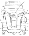
従来の集塵機を図5及び図6を用いて説明する。図5及び図6に示す集塵機は主に床面を掃除する用途で広く使用されており、この集塵機のフロート装置16は、フロート13とこのフロート13を収納するフロートホルダ14で形成されている。上記フロート13は液体に浮くよう中空で逆円錐形を成しており、フロートホルダ14は側面部に何ヵ所かの窓部を有した逆円錐形で、ネジ17等によりモーターケース1に固定されている。またフロート13はフロートホルダ14内で上下方向に移動することができる。更に集塵量を確保するためにモーターケース1の外径に比べフロートホルダ14の外径は1/3程度で形成されている。
【0003】
集塵ファン4の回転により発生する吸い込み力により、集塵された液体19や粉塵20が含まれた液体19は、吸込口21を通りダストケース7内部に空気と共に搬送される。空気と共に搬送された液体19や粉塵20が含まれた液体19は、ダストケース7内部に取り付けられたフィルタ装置6の濾過機能により粉塵20と空気に分離され、フィルタ装置6の外周面で捕集される。液体19は自然落下により、ダストケース7内に収納される。空気はフィルタ装置6を通過してフィルタ装置6の内側部を通り、モーターケース1内部に吸引される。フィルタ装置6の外周面で捕集された粉塵20は自然落下し、ダストケース7内部に収納される。液体19や粉塵20が含まれた液体19が集塵され続けるとダストケース7内の水位が上がり、集塵した液体19が吸込口21から逆流したり、吸気口5よりモーターケース1内まで侵入してしまい排気口18から集塵機の外部にまき散らかされてしまう。これらを防止するために、フロート装置16が設けられている。液体19や粉塵20が含まれた液体19が集塵され続けるとダストケース7内の水位が上がる。これと共にフロート13も上方に移動する。モーターケース1の下部の吸気口5にフロート13が近づくと、集塵ファン4の回転により発生する吸い込み力により、フロート13は吸いつけられ、吸気口5を塞ぎ、それ以上集塵されなくなり、集塵した液体19が吸込口21から逆流したり、吸気口5よりモーターケース1内まで侵入してしまい排気口18から集塵機の外部にまき散らかされてしまうのを防止している。
【0004】
【発明が解決しようとする課題】
集塵した粉塵の廃棄時や集塵機のメンテナンス時、ダストケースからモーターケースを取り出して周辺に配置する。配置する時、モーターケースを縦に配置すると不安定で倒れやすい。また、これを防ごうとして、横にして配置するとモーターケースが略円形のため、転がり易い。モーターケースが倒れたり、転がると、モーターケースの破損、モーターケース外観部、床面に傷の発生、モーターケースの周辺に置かれた物の破損、作業者に対する安全性が低下してしまうという問題が起きる。また、集塵した液体や粉塵の廃棄時や集塵機のメンテナンス時のモーターケースの配置の仕方が一定せず、これによりハンドル位置が一定せず、再度ダストケースにモーターケースを取付ける時に取付けるのが面倒であるという問題がある。
【0005】
本発明の目的は、上記問題を解消し、モーターケースの破損、モーターケース外観部、床面に傷の発生、モーターケースの周辺に置かれた物の破損や、不意の怪我等をなくすことである。また、集塵した液体や粉塵の廃棄時や集塵機のメンテナンス時のモータケースの配置の仕方が決まることにより、モーターケースのダストケースへの再取付けを簡易にすることである。
【0006】
【課題を解決するための手段】
上記目的は、フロート装置の底部につば部を設けることにより達成される。
【0007】
【発明の実施の形態】
本実施例における集塵機を図1〜図4を用いて説明する。図1は本実施例における集塵機のフロート装置の一例を示す一部縦断側面図、図2は本実施例における集塵機のフロート装置の一例を示す底面図、図3は本実施例における集塵機のフロート装置の一例を示す底面図、図4は本実施例における集塵機のフロート装置の一例を示す一部縦断側面図である。
【0008】
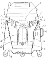
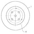
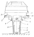
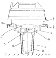
図1〜図4において、モーターケ−ス1の内部には、電動機2がその出力軸3を鉛直方向下方となるように配設し、この出力軸3には直結された遠心形集塵ファン4を設け、この集塵ファン4の吸気口5をモーターケース1の下面中心部に設ける。モーターケース1の下方には、フィルター装置6とダストケース7を配設する。フィルター装置の上面外周部8はモーターケースの下面外周部9に設けられたシールパッキン10とダストケースの上面外周部11間に挟まれ、モーターケース1とダストケース7がクランプなどにより締結されることにより、圧着・密閉される。ダストケース7の側面には、集塵ホースを接続するための吸込口21が設けられる。フロート装置16底部には、つば15部が設けられている。なお、つば部15の形状はモーターケース1に取付け易いように図4のような形状でも良い。
【0009】
上記のように構成された集塵機の粉塵20の廃棄時やメンテナンス時、モーターケース1をつば部15が下方にくるように配置する。こうすれば、倒れづらく、転がらず、また、再度取付ける時に取付け易いという効果が得られる。
【0010】
【発明の効果】
本発明によれば、モーターケースの破損、モーターケース外観部、床面に傷の発生、モーターケースの周辺に置かれた物の破損や、不意の怪我等を防止することができる。また、集塵した液体や粉塵の廃棄時や集塵機のメンテナンス時のモータケースの配置の仕方が決まることにより、モーターケースのダストケースへの再取付けを簡易にすることができる。
【図面の簡単な説明】
【図1】 本発明になる集塵機のフロート装置の一例を示す一部縦断側面図である。
【図2】 本発明になる集塵機のフロート装置の一例を示す底面図である。
【図3】 本発明になる集塵機のフロート装置の一例を示す底面図である。
【図4】 本発明になる集塵機のフロート装置の一例を示す一部縦断側面図である。
【図5】 従来の集塵機のフロート装置を示す一部縦断側面図である。
【図6】 従来の集塵機のフロート装置を示す一部縦断側面図である。
【符号の説明】
1はモーターケース、7はダストケース、13はフロート、15はつば部、16はフロート装置である。[0001]
BACKGROUND OF THE INVENTION
The present invention relates to a dust collector used for collecting dust and the like.
[0002]
[Prior art]
A conventional dust collector will be described with reference to FIGS. The dust collector shown in FIG. 5 and FIG. 6 is widely used mainly for the purpose of cleaning the floor surface, and the
[0003]
The liquid 19 containing the collected liquid 19 and the
[0004]
[Problems to be solved by the invention]
Remove the motor case from the dust case and place it around when discarding the collected dust or maintaining the dust collector. When placing the motor case, it is unstable and easy to fall down. In order to prevent this, if the motor case is placed sideways, the motor case is almost circular and therefore easy to roll. If the motor case falls or rolls, the motor case may be damaged, the external appearance of the motor case may be damaged, the objects placed around the motor case may be damaged, and the safety for workers may be reduced. Happens. In addition, the way the motor case is arranged when discarding collected liquid or dust or maintenance of the dust collector is not constant, which makes the handle position non-constant, and it is troublesome to attach the motor case to the dust case again. There is a problem that.
[0005]
The object of the present invention is to eliminate the above problems and eliminate damage to the motor case, external appearance of the motor case, scratches on the floor, damage to objects placed around the motor case, and unexpected injuries. is there. Further, it is to simplify the reattachment of the motor case to the dust case by determining the arrangement of the motor case at the time of disposal of the collected liquid or dust or maintenance of the dust collector.
[0006]
[Means for Solving the Problems]
The above object is achieved by providing a flange at the bottom of the float apparatus.
[0007]
DETAILED DESCRIPTION OF THE INVENTION
The dust collector in a present Example is demonstrated using FIGS. 1-4. FIG. 1 is a partially longitudinal side view showing an example of a float device for a dust collector in this embodiment, FIG. 2 is a bottom view showing an example of a float device for a dust collector in this embodiment, and FIG. 3 is a float device for a dust collector in this embodiment. FIG. 4 is a partially longitudinal side view showing an example of a float apparatus for a dust collector in the present embodiment.
[0008]
1 to 4, an
[0009]
At the time of disposal or maintenance of the
[0010]
【The invention's effect】
According to the present invention, it is possible to prevent damage to the motor case, generation of scratches on the outer surface of the motor case, the floor surface, damage to objects placed around the motor case, unexpected injury, and the like. In addition, since the arrangement of the motor case at the time of disposal of the collected liquid or dust or maintenance of the dust collector is determined, the reattachment of the motor case to the dust case can be simplified.
[Brief description of the drawings]
FIG. 1 is a partially longitudinal side view showing an example of a dust collector float device according to the present invention.
FIG. 2 is a bottom view showing an example of a dust collector float device according to the present invention.
FIG. 3 is a bottom view showing an example of a dust collector float device according to the present invention.
FIG. 4 is a partially longitudinal side view showing an example of a dust collector float device according to the present invention.
FIG. 5 is a partially longitudinal side view showing a conventional float device of a dust collector.
FIG. 6 is a partially longitudinal side view showing a conventional float device of a dust collector.
[Explanation of symbols]
1 is a motor case, 7 is a dust case, 13 is a float, 15 is a collar part, and 16 is a float device.
Claims (2)
Priority Applications (1)
| Application Number | Priority Date | Filing Date | Title |
|---|---|---|---|
| JP2002241126A JP4134635B2 (en) | 2002-08-21 | 2002-08-21 | Dust collector |
Applications Claiming Priority (1)
| Application Number | Priority Date | Filing Date | Title |
|---|---|---|---|
| JP2002241126A JP4134635B2 (en) | 2002-08-21 | 2002-08-21 | Dust collector |
Publications (2)
| Publication Number | Publication Date |
|---|---|
| JP2004073684A JP2004073684A (en) | 2004-03-11 |
| JP4134635B2 true JP4134635B2 (en) | 2008-08-20 |
Family
ID=32023718
Family Applications (1)
| Application Number | Title | Priority Date | Filing Date |
|---|---|---|---|
| JP2002241126A Expired - Lifetime JP4134635B2 (en) | 2002-08-21 | 2002-08-21 | Dust collector |
Country Status (1)
| Country | Link |
|---|---|
| JP (1) | JP4134635B2 (en) |
-
2002
- 2002-08-21 JP JP2002241126A patent/JP4134635B2/en not_active Expired - Lifetime
Also Published As
| Publication number | Publication date |
|---|---|
| JP2004073684A (en) | 2004-03-11 |
Similar Documents
| Publication | Publication Date | Title |
|---|---|---|
| US10092148B2 (en) | Vacuum bypass vent and vacuums incorporating such bypass vents | |
| US20030182757A1 (en) | Filtration arrangement of a vacuum cleaner | |
| CN111820816B (en) | Dry and wet dual-purpose sewage tank assembly of water machine | |
| US10183250B2 (en) | Dust collector capable of recollecting particulate dust in the filter barrel | |
| US3034273A (en) | Liquid collecting vacuum cleaner | |
| KR860001634B1 (en) | Dry and Wet Vacuum Cleaner | |
| KR20110090266A (en) | Filter assembly of air purifier with automatic cleaning function and air purifier having the same | |
| KR102258528B1 (en) | An industrial vacuum cleaner having dust cleaner | |
| CN101675871A (en) | Dust collector dust collecting bucket | |
| JP2016047271A (en) | Dust collector and self-propelled vacuum cleaner provided with same | |
| JP4134635B2 (en) | Dust collector | |
| US6342084B1 (en) | Vacuum cleaner | |
| JP2018054205A (en) | Range hood | |
| KR102234655B1 (en) | Filterless dust collector | |
| KR100420169B1 (en) | A Cyclone-dust collecting apparatus for vacuum cleaner | |
| JP2005007066A (en) | Liquid suction device | |
| JPS599698Y2 (en) | Dryer dust separation device | |
| EP0484894A1 (en) | Separator for solid and liquid particles from an air current | |
| JP6200629B2 (en) | Self-propelled vacuum cleaner | |
| JPH0739939Y2 (en) | Cleaning machine | |
| JPH02215434A (en) | Vacuum cleaner | |
| JP4438673B2 (en) | Filtration water supply device | |
| JPS591645Y2 (en) | vacuum cleaner | |
| JPH0350847Y2 (en) | ||
| JPH11155789A (en) | Floor polisher with dust collection function |
Legal Events
| Date | Code | Title | Description |
|---|---|---|---|
| A621 | Written request for application examination |
Free format text: JAPANESE INTERMEDIATE CODE: A621 Effective date: 20050812 |
|
| A977 | Report on retrieval |
Free format text: JAPANESE INTERMEDIATE CODE: A971007 Effective date: 20080125 |
|
| A131 | Notification of reasons for refusal |
Free format text: JAPANESE INTERMEDIATE CODE: A131 Effective date: 20080129 |
|
| A521 | Request for written amendment filed |
Free format text: JAPANESE INTERMEDIATE CODE: A523 Effective date: 20080331 |
|
| TRDD | Decision of grant or rejection written | ||
| A01 | Written decision to grant a patent or to grant a registration (utility model) |
Free format text: JAPANESE INTERMEDIATE CODE: A01 Effective date: 20080507 |
|
| A01 | Written decision to grant a patent or to grant a registration (utility model) |
Free format text: JAPANESE INTERMEDIATE CODE: A01 |
|
| A61 | First payment of annual fees (during grant procedure) |
Free format text: JAPANESE INTERMEDIATE CODE: A61 Effective date: 20080520 |
|
| R150 | Certificate of patent or registration of utility model |
Free format text: JAPANESE INTERMEDIATE CODE: R150 Ref document number: 4134635 Country of ref document: JP Free format text: JAPANESE INTERMEDIATE CODE: R150 |
|
| FPAY | Renewal fee payment (event date is renewal date of database) |
Free format text: PAYMENT UNTIL: 20110613 Year of fee payment: 3 |
|
| FPAY | Renewal fee payment (event date is renewal date of database) |
Free format text: PAYMENT UNTIL: 20110613 Year of fee payment: 3 |
|
| FPAY | Renewal fee payment (event date is renewal date of database) |
Free format text: PAYMENT UNTIL: 20120613 Year of fee payment: 4 |
|
| FPAY | Renewal fee payment (event date is renewal date of database) |
Free format text: PAYMENT UNTIL: 20130613 Year of fee payment: 5 |
|
| FPAY | Renewal fee payment (event date is renewal date of database) |
Free format text: PAYMENT UNTIL: 20140613 Year of fee payment: 6 |
|
| S533 | Written request for registration of change of name |
Free format text: JAPANESE INTERMEDIATE CODE: R313533 |
|
| R350 | Written notification of registration of transfer |
Free format text: JAPANESE INTERMEDIATE CODE: R350 |
|
| EXPY | Cancellation because of completion of term |