JP4134563B2 - Rear cargo compartment structure of vehicle - Google Patents
Rear cargo compartment structure of vehicle Download PDFInfo
- Publication number
- JP4134563B2 JP4134563B2 JP2002023664A JP2002023664A JP4134563B2 JP 4134563 B2 JP4134563 B2 JP 4134563B2 JP 2002023664 A JP2002023664 A JP 2002023664A JP 2002023664 A JP2002023664 A JP 2002023664A JP 4134563 B2 JP4134563 B2 JP 4134563B2
- Authority
- JP
- Japan
- Prior art keywords
- tire
- floor
- vehicle
- luggage compartment
- compartment
- Prior art date
- Legal status (The legal status is an assumption and is not a legal conclusion. Google has not performed a legal analysis and makes no representation as to the accuracy of the status listed.)
- Expired - Fee Related
Links
Images


Description
【0001】
【発明の属する技術分野】
本発明は車両の後部荷室構造に関し、特に、後部荷室にタイヤを収容保持する構造、1対のリヤサスペンションダンパーを連結する構造を改善したものに関する。
【0002】
【従来の技術】
従来、車両の後部荷室にタイヤを収容保持する種々の構造が存在する。図11(a)〜(c)に示す車両の後部荷室100 は、荷室フロアが後部フロア102 と後部フロア102 よりも一段高い前部フロア103 とに区分され、(a)ではタイヤ105 が後部フロア102 上に水平姿勢で保持され、(b)ではタイヤ105 が前部フロア103 上に水平姿勢で保持され、(c)ではタイヤ105 が後部フロア102 上に荷室後壁106 に沿う鉛直姿勢で保持されている。
【0003】
また、特開平5-85416 号公報には、荷室の後部フロアが前部フロアに対して低床で前方下がりの傾斜状に形成され、その後部フロア上にタイヤを載置して前方下りの傾斜姿勢で保持する構造が開示され、特開平6-107246号公報には、荷室の後部フロアが後方下がりの傾斜状に形成され、その後部フロア上にタイヤを載置して後方下りの傾斜姿勢で保持する構造が開示されている。
【0004】
一方、左右1対のサスペンションダンパーをストラットタワーバーで連結する技術は広く実用に供されているが、特開平6-344824号公報には、1対のフロントサスペンションダンパーを連結するストラットタワーバーに、タイヤを取外し可能に取付けて保持する技術が開示されている。
【0005】
【発明が解決しようとする課題】
図11(a)(b)の後部荷室100 の構造は、タイヤ105 を荷室フロア上に水平姿勢で載置して保持するものであるため、荷室フロア上を荷物収納のために有効に使用することができない。また、図11(a)の構造では、車両後突時、タイヤ105 によって車体の後部フロア部分が変形しにくくなるため、衝突エネルギーを吸収する十分なクラッシャブルゾーンZを車体の後部荷室部分に確保しにくく望ましくない。
【0006】
図11(b)の構造では、タイヤ105 の後側部分がクラッシャブルゾーンZにかかって、実質的なクラッシャブルゾーンが短くなり、また、車両後突時にタイヤ105 が車室に侵入する虞があり、それを防止する補強対策も別途必要となる。図11(c)の構造では、タイヤ105 によって荷室開口部107 から荷室100 に荷物を出し入れしにくくなり、荷室100 の使い勝手が悪くなる。
【0007】
また、特開平5-85416 号公報や特開平6-107246号公報に記載の後部荷室の構造でも、タイヤを後部フロアに沿った傾斜姿勢で載置して保持するものであるので、荷室フロア(特に後部フロア)上を荷物収納のために有効に使用することができないし、後部フロアも傾斜状の特殊な形状となるため製作上不利である。また、衝突エネルギーを吸収する十分なクラッシャブルゾーンを車体の後部荷室部分に確保しにくいこと、等の虞もある。
【0008】
一方、特開平6-344824号公報に記載の構造は、ストラットタワーバーにより1対のフロントサスペンションダンパーを連結すると共に、そのストラットタワーバーにスペアタイヤを水平姿勢で取外し可能に取付けて保持するものであり、後部荷室にタイヤを収容保持するものではなく、また、このストラットタワーバーの高さ位置を調節できるものでもない。
【0009】
本発明の目的は、車両の後部荷室構造において、後部荷室の荷室フロア上を荷物収納のために有効に使用できるように後部荷室にタイヤを保持すること、クラッシャブルゾーンを車体の後部荷室部分に十分に確保できるようにすること、また、1対のリヤサスペンションダンパーを連結して車体剛性を高めると共に上記の目的を達成すること、等である。
【0010】
【課題を解決するための手段】
請求項1の車両の後部荷室構造は、荷室フロアと、この荷室フロアの車幅方向両端の上側に設けられた1対の側壁部と、荷室開口部とを備えた車両の後部荷室の構造において、前記1対の側壁部に夫々連結された1対のリヤサスペンションダンパーと、前記後部荷室内において車幅方向に延びるとともに、車幅方向両端部が高さ方向位置を調節可能に且つ着脱自在に1対の側壁部のダンパー連結部付近に夫々連結された補強部材と、前記補強部材にタイヤを取外し可能に取付けて保持するタイヤ保持機構と、前記荷室フロアのうちの前部フロアに設けられ、前記タイヤの前下端部を受け止め可能なストッパー部とを設け、前記タイヤが後部荷室の後部に荷室空間を残すように、後部荷室の前部に前方下りの傾斜姿勢で収容保持されるように構成し、前記補強部材は、水平方向に延びる保持部と、この保持部の車幅方向両端部から下方へ屈曲した1対の連結部とを有し、これら連結部が前記1対の側壁部に、ブラケットと連結金具とボルトを介して固定解除可能且つ高さ方向位置調節可能に固定されることを特徴とするものである。
この場合、前記ストッパー部は、前記荷室フロアの前端部に設けられた車幅方向に延びるクロスメンバーにより構成してもよい(請求項2)。この場合、前記補強部材が前記タイヤの前方側付近に設けられ、前記補強部材に装着された前記タイヤ保持機構により前記タイヤを上面側から保持するようにしてもよい(請求項3)。また、前記荷室フロアは後部フロアとこの後部フロアよりも一段高い前部フロアとを有し、保持されたタイヤの下端近傍に前部フロアが位置するようにしてもよい(請求項4)。
【0011】
請求項5の車両の後部荷室構造は、請求項4において、前記車体後部において、左右2本のリヤサイドフレームが前後方向に延び且つ車幅方向向きのクロスメンバーで連結され、これらリヤサイドフレームとクロスメンバーの上部側に前部フロアが設けられ、2本のリヤサイドフレームの間に後部フロアが設けられるようにしてもよい。
【0012】
【0013】
【0014】
【0015】
【発明の実施の形態】
以下、本発明の実施の形態について図面を参照しながら説明する。本実施形態は、前席シートと後席シートとを有する2ドア又は4ドアの乗用車において、後席シートの後方に設けられトランクリッドで開閉される後部荷室の構造に、本発明を適用した場合の一例である。
【0016】
図1に示すように、自動車の車室1の後部に、シートクッション3とシートバック4とヘッドレスト5とを有する後席シート2が設けられ、この後席シート2の後方に後部荷室6(以下、荷室6という)が設けられている。シートバック4は、実線で示す起立姿勢で車室1と荷室6とを仕切り、鎖線で示すように、シートバック4を前側へ倒してシートクッション3の上側に折り重ねると、車室1と荷室6とが連通する所謂トランクスルー状態になる。
【0017】
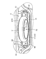
図1、図2に示すように、荷室6は、荷室フロア10と、1対の荷室側壁12と、荷室後壁13と、荷室開口部14とを備え、起立姿勢のシートバック4と、そのシートバック4の上部後側に設けられたパッケージトレイ11により車室1側と仕切られている。荷室開口部14はトランクリッド15により開閉され、この荷室開口部14からタイヤTが荷室6に出し入れされ、荷室6の前部に収容されたタイヤTが前下がりの傾斜姿勢で保持されるように構成してある。
荷室フロア10は、低床の略水平な後部フロア16と、この後部フロア16よりも一段高い高床の略水平な前部フロア17とを有する。
【0018】
ここで、図1、図3に示すように、車体後部には、左右2本のリヤサイドフレーム20が前後方向に延びて、車幅方向向きのクロスメンバ21,22で連結され、これらリヤサイドフレーム20とクロスメンバ21,22の上部側に前部フロア17が設けられ、2本のリヤサイドフレーム20の略下端部の間に後部フロア16が設けられている。また、起立姿勢のシートバック4の上部後側でパッケージクロスメンバ23が車幅方向に延び、リヤウインドガラス7の後下端部付近でリヤパッケージクロスメンバ24が車幅方向に延び、これらクロスメンバ23,24にパッケージトレイ11が連結されている。
【0019】
図1〜図4に示すように、荷室6の左右両側部分には、夫々、タイヤハウス40と、このタイヤハウス40の一部を含むダンパー収容部41が荷室6に張り出すように設けられ、各ダンパー収容部41の凹部41aにリヤサスペンションダンパー30(以下、ダンパー30という)の上半部が収容されている。ダンパー30は、シリンダ31とピストンロッド32とを有し、シリンダ31からピストンロッド32が上方へ延びるように略鉛直姿勢で取付けられ、シリンダ31の下端の連結部31aが後輪を回転自在に支持するナックルに連結されている。
【0020】
図3〜図5に示すように、リヤサイドフレーム20の車幅方向外側に1対のダンパー支持部33が取付けられ、各ダンパー支持部33の水平部が前部フロア17と略同一高さになって略連続し、ダンパー支持部33に形成された開口33aにダンパー30が挿通している。シリンダ31の上部とそこから延びるピストンロッド32は、ダンパー支持部33よりも上側に位置して、筒状のダンパーサポート34で覆われている。
【0021】
このダンパーサポート34の上端部がピストンロッド32の上端部分に連結され、ダンパーサポート34の下端部がダンパー支持部33に連結されている。また、ダンパーサポート34の上端部分は、ダンパー収容部41の凹部41aの側壁部45、及び、ダンパー収容部41の凹部41aを部分的に覆う側壁部46に連結されている。尚、本実施形態の場合、側壁部45,46が、特許請求の範囲の側壁部に相当する。尚、図4には側壁部46を図示省略している。
【0022】
尚、ダンパー支持部33の下側において、シリンダ31にはコイルバネ35が外装され、コイルバネ35の上端がダンパー支持部33のバネ受け部に受け止められ、下端がシリンダ31の下端部分のバネ受け部に受け止められている。尚、ピストンロッド32には、バウンドストッパ、ラバーブッシュ(図示略)が取付けられ、これらの間にダンパーサポート34の上端部が連結されている。
【0023】
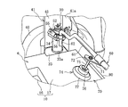
図3〜図6に示すように、ダンパーサポート34の上端部分を側壁部45,46に連結する構造については、ダンパー収容部41の凹部41aに、ダンパーサポート34を囲繞する平面視コの字状の車体側ブラケット50が嵌合されて、凹部41aの側壁部45に溶接等で固定され、一方、ダンパーサポート34の上端部分にはダンパー側ブラケット51が溶接等で固定されている。
【0024】
車体側ブラケット50に、側壁部46を挟んで連結ブラケット52の前後両端部が荷室6側からボルト53で連結され、連結ブラケット52の中央部分がダンパー側ブラケット51にボルト54で連結されている。また、車体側ブラケット50(側壁部46)には、連結ブラケット52と共にブラケット55がボルト53によりが共締めされ、このブラケット55に連結金具56がボルト57で連結されている。少なくとも、連結ブラケット52、ブラケット55、連結金具56は、荷室6に臨むものとなる。
【0025】
さて、図1〜図6に示すように、この荷室6の構造においては、荷室6内において車幅方向に延びる保持部材60(補強部材)と、この保持部材60にタイヤTを取外し可能に取付けて保持するタイヤ保持機構70とを設けて、タイヤTを荷室6の前部に収容して前方下がりの傾斜姿勢で保持可能に構成すると共に、保持部材60により、左右1対のダンパー30を連結するように構成してある。
【0026】
保持部材60はパイプ材で構成されて、後部フロア16の上側に配設され、その長さは後部フロア16の車幅方向幅よりも少し短い。保持部材60は、略水平な保持部61と、この保持部61の車幅方向両端部から下方へ屈曲した1対の連結部62とを有し、これら連結部62が、1対の側壁部46のダンパー連結部付近において、前記ブラケット55と連結金具56とボルト57等によって夫々着脱自在に連結されている。
【0027】
また、保持部材60は、その高さ方向位置を調節可能に1対の連結部62が1対の側壁部46のダンパー連結部付近に夫々連結されている。即ち、1対の連結部62をボルト57を弛めて固定解除すると、保持部材60の高さ方向位置を調節することができ、その高さ方向位置を調節した後、ボルト57を締めて1対の連結部62を固定できる。また、1対の連結部62をボルト57を弛めて固定解除し、ブラケット55と連結金具56の間から引き抜いて、保持部材60を取外すことができる。
【0028】
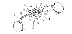
図4、図7〜図9に示すように、タイヤ保持機構70は、保持部材60の長さ方向中央部分に回動可能に外嵌状に装着された保持片71、保持片71に固着されたナット72、テーパ穴73aが形成されたリテーナ73、リテーナ73のテーパ穴73aを挿通可能なロッド75とロッド75の端部に連結された押圧部76と操作部77とを有する回動部材74等で構成されている。
【0029】
タイヤ保持機構70でタイヤTを保持部材60に取付ける場合、先ず、タイヤTのディスクホイールT1の穴T2にリテーナ73をタイヤ裏面側から内嵌させ、タイヤ裏面側に向かって広がるガイド穴73aに、タイヤ裏面側から回動部材74のロッド75を挿通させる。この場合、ロッド75はテーパ穴73aにガイドされるため、ロッド75をテーパ穴73aに容易に挿通させることができる。
【0030】
リテーナ73のテーパ穴73aに挿通した回動部材74のロッド75の先端部を、保持片71に固着されたナット72に螺合させるように、操作部77を操作して回動部材74を回動させ、続けて、回動部材74を回動させることにより、間隔が狭まる保持片71と押圧部76とでタイヤTのディスクホイールT1の中心部分が挟持されて、タイヤTが保持部材60に保持される。
【0031】
図1〜図4等に示すように、前部フロア17の前端部には、クロスメンバ21の一部又は別途部材からなるストッパー部80が設けられ、このストッパー部80でタイヤTの前下端部を受け止めた状態で、タイヤ保持機構70によりタイヤTを保持部材60に取付けることにより、タイヤTが荷室6の後部に荷室空間を残すように荷室6の前部に収容されて前方下りの傾斜姿勢で保持される。
【0032】
以上説明した荷室6の構造の作用・効果について説明する。
荷室6内において車幅方向に延びる保持部材60であって、車幅方向両端部が1対の側壁部45,46のダンパー連結部付近に夫々連結された保持部材60を設けたので、車体剛性を高めることができる。
【0033】
更に、保持部材60にタイヤTを取外し可能に取付けて保持するタイヤ保持機構70を設け、また、前部フロア17の前端部に、タイヤTの前下端部を受け止め可能なストッパー部80を設けたので、タイヤTを荷室6の後部に荷室空間を残すように荷室6の前部に収容して、前方下りの傾斜姿勢で保持できる。
【0034】
このように、保持部材60は、車体剛性を高める機能と、タイヤ保持機構70と協働してタイヤTを荷室6の後部で傾斜姿勢で保持する機能とを両立できる部材とすることができ、これら両機能を簡単な構成で達成することができて製作コスト的に有利になる。
【0035】
タイヤTを荷室6の後部に荷室空間を残すように荷室6の前部に収容して、前方下りの傾斜姿勢で保持できるので、荷室フロア10上を荷室収納の為に有効に使用して、大きな収納スペースを確保できるから、後部荷室の使い勝手がよくなる。特に、前部フロア17に対して深さの深い後部フロア16に、背丈の高い荷物を載置して収容できるようになる。更に、車両後突時に変形させるクラッシャブルゾーンを車体の後部荷室部分に十分に確保して、衝突安全性を高めることができる。
【0036】
保持部材60の高さ方向位置を調節可能に、保持部材60の車幅方向両端部を1対の側壁部46に夫々連結したので、タイヤTの種類(サイズ等)に応じて保持部材60の高さ位置を調節して、そのタイヤTを保持機構70で保持部材60に保持した場合に、タイヤTの前下端部がストッパー部80に受け止められた状態で、タイヤTを前方下りの傾斜姿勢で確実に保持できるようになる。
【0037】
しかも、保持部材60の車幅方向両端部を1対の側壁部46に夫々着脱自在に連結したので、保持部材60が不要な場合に、保持部材60を取外して荷室6の収納スペースを最大にすることができる。
【0038】
また、ストッパー部80を設けることにより、前部フロア17に水平姿勢で載置されタイヤTを前方下りの傾斜姿勢にする際に、そのストッパー部80が補助となり、前記傾斜姿勢への切換えを容易に行うことが可能になる。また、タイヤTが前記傾斜姿勢で保持されている場合、車両後突時、前方へ移動しようとするタイヤTの前下端部をストッパー部80で受け止めて、タイヤTが車室1に侵入するのを防止することができる。
【0039】
尚、使用しているタイヤTaがパンク等で損傷し、そのタイヤTaをスペアタイヤTと交換した場合等、図10に示すように、使用済みのタイヤTaを、保持部材60の下側に位置させるように荷室6に収容することができる。この場合、保持部材60の高さ位置を上げるように調節すること、又は、保持部材60を取外すことにより、タイヤTaを収納し易くしてもよい。また、タイヤTaにランフラットタイヤを使用し、タイヤTaのパンク時にタイヤTaを荷室6に収容する必要がない場合や、スペアタイヤTを保持部材60に保持して荷室6に収容しておく必要がない場合には、荷室6に比較的大きな荷物を収容することができる。この場合、荷物の大きさに合わせて保持部材60の高さ位置を調節できるし、保持部材60を取外してもよい。
【0040】
尚、本発明の趣旨を逸脱しない範囲において種々の変更を付加して実施することができる。尚、後席シートのない所謂2シータ自動車、5ドアの所謂ハッチバック型の自動車等、種々の自動車や自動車以外の車両に装備される後部荷室の構造に、本発明を適用可能であることはいうまでもない。
【0041】
【発明の効果】
請求項1の車両の後部荷室構造によれば、荷室フロアと、この荷室フロアの車幅方向両端の上側に設けられた1対の側壁部と、荷室開口部とを備え、更に、1対の側壁部に夫々連結された1対のリヤサスペンションダンパーと、後部荷室内において車幅方向に延びるとともに、車幅方向両端部が高さ方向位置を調節可能に且つ着脱自在に1対の側壁部のダンパー連結部付近に夫々連結された補強部材と、補強部材にタイヤを取外し可能に取付けて保持するタイヤ保持機構と、荷室フロアのうちの前部フロアに設けられ、タイヤの前下端部を受け止め可能なストッパー部とを設け、タイヤが後部荷室の後部に荷室空間を残すように、後部荷室の前部に前方下りの傾斜姿勢で収容保持されるように構成し、補強部材は、水平方向に延びる保持部と、この保持部の車幅方向両端部から下方へ屈曲した1対の連結部とを有し、これら連結部が1対の側壁部に、ブラケットと連結金具とボルトを介して固定解除可能且つ高さ方向位置調節可能に固定されるように構成した。
【0042】
1対の側壁部に夫々連結された1対のリヤサスペンションダンパーと、後部荷室内において車幅方向に延びるとともに、車幅方向両端部が高さ方向位置を調節可能に且つ着脱自在に1対の側壁部のダンパー連結部付近に夫々連結された補強部材とを設けたので、車体 剛性を高めると共に、補強部材の高さ方向位置を適当に調節して、タイヤや荷物等の収納性を高めることができる。また、補強部材が不要な場合、その補強部材を取り外して収納スペースを最大にすることができる。
補強部材にタイヤを取外し可能に取付けて保持するタイヤ保持機構を設けたので、これら補強部材及びタイヤ保持機構により、タイヤを後部荷室の前部に収容し適当な高さ位置において前方下りの傾斜姿勢で保持でき、これにより、後部荷室の後部に荷室空間を残すことができ、荷室フロア上の大部分を荷物収納の為に有効に使用して、大きな収納スペースを確保できるから、後部荷室の使い勝手がよくなるし、車両後突時に変形させるクラッシャブルゾーンを車体の後部荷室部分に確保して、衝突安全性を高めることができる。
タイヤを後部荷室の後部に荷室空間を残すように後部荷室の前部に収容保持するように構成したので、車両後突時に変形させるクラッシャブルゾーンを車体の後部荷室部分に確保することができ、また、後部荷室の使い勝手がよくなる。
タイヤを前方下りの傾斜姿勢で保持するように構成したので、荷室フロア上の大部分を荷物収納の為に有効に使用して、大きな収納スペースを確保できるから、荷物収納性が高まり、車両後突時に変形させるクラッシャブルゾーンを車体の後部荷室部分に十分に確保して、衝突安全性を高めることができる。
荷室フロアのうちの前部フロアに設けられ、タイヤの前下端部を受け止め可能なストッパー部を設けたので、タイヤを前方下りの傾斜姿勢で確実に保持できると共に、前部フロアに水平姿勢で載置されタイヤを前方下りの傾斜姿勢にする際に、そのストッパー部が補助となり、前記傾斜姿勢への切換えを容易に行うことが可能になる。また、タイヤが前記傾斜姿勢で保持されている場合、車両後突時、前方へ移動しようとするタイヤの前下端部をストッパー部で受け止めて、タイヤが車室に侵入するのを防止できる。
【0043】
請求項2の車両の後部荷室構造によれば、ストッパー部は、荷室フロアの前端部に設けられた車幅方向に延びるクロスメンバーにより構成されているので、クロスメンバーによりストッパ部を容易に形成することができる。
【0044】
請求項3の車両の後部荷室構造によれば、補強部材が前記タイヤの前方側付近に設けられ、補強部材に装着されたタイヤ保持機構によりタイヤを上面側から保持するので、タイヤ保持機構に邪魔されることなく、荷室空間を有効利用することができる。
【0045】
請求項4の車両の後部荷室構造によれば、荷室フロアは後部フロアとこの後部フロアよりも一段高い前部フロアとを有し、保持されたタイヤの下端近傍に前部フロアが位置するので、タイヤの少なくとも一部を前部フロアに載置させて荷重支持することができ、タイヤを安定した状態で保持することができる。
【0046】
請求項5の車両の後部荷室構造によれば、車体後部において、左右2本のリヤサイドフレームが前後方向に延び且つ車幅方向向きのクロスメンバーで連結され、これらリヤサイドフレームとクロスメンバーの上部側に前部フロアが設けられ、2本のリヤサイドフレームの間に後部フロアが設けられているので、車両後突時に変形させるクラッシャブルゾーンを車体の後部荷室部分に十分に確保することができる。
【0047】
【0048】
【0049】
【図面の簡単な説明】
【図1】本発明の実施形態に後部荷室の側面側からの縦断面図である。
【図2】スペアタイヤを収容保持した後部荷室の背面図である。
【図3】リヤサスペンションダンパーを含む後部荷室の縦断面図である。
【図4】後部荷室の前部の後方上側からの斜視図である。
【図5】リヤサスペンションダンパーと保持部材の連結部分の斜視図である。
【図6】リヤサスペンションダンパーと保持部材の連結部分の平面図である。
【図7】保持部材とタイヤ保持機構とタイヤの後方上側からの斜視図である。
【図8】保持部材とタイヤ保持機構とタイヤの後方下側からの斜視図である。
【図9】保持機構の分解斜視図である。
【図10】使用済みのタイヤを収容保持した後部荷室の背面図である。
【図11】従来技術に係る後部荷室の構造を示し、(a)はタイヤを後部フロア上に水平姿勢で保持したもの、(b)はタイヤを前部フロア上に水平姿勢で保持したもの、(c)はタイヤを後部フロア上に鉛直姿勢で保持したものである。
【符号の説明】
6 後部荷室
10 荷室フロア
14 荷室開口部
30 リヤサスペンションダンパー
46 側壁部
60 保持部材(補強部材)
70 タイヤ保持機構
80 ストッパー部[0001]
BACKGROUND OF THE INVENTION
The present invention relates to a rear luggage compartment structure of a vehicle, and more particularly to an improved structure for housing and holding tires in a rear luggage compartment and a structure for connecting a pair of rear suspension dampers.
[0002]
[Prior art]
Conventionally, there are various structures for accommodating and holding tires in the rear luggage compartment of a vehicle. 11 (a) to 11 (c), the
[0003]
Further, in Japanese Patent Application Laid-Open No. 5-85416, the rear floor of the cargo compartment is formed in a slanted shape with a lower floor and a front lowering with respect to the front floor, and a tire is placed on the rear floor to lower the front lowering. A structure for holding in an inclined posture is disclosed, and Japanese Patent Application Laid-Open No. 6-107246 discloses that a rear floor of a cargo compartment is formed in a downwardly inclined shape, and a tire is placed on the rear floor to incline backward and downwardly. A structure for holding in a posture is disclosed.
[0004]
On the other hand, the technology of connecting a pair of left and right suspension dampers with a strut tower bar is widely used in practice, but JP-A-6-344824 discloses a strut tower bar that connects a pair of front suspension dampers. A technique for detachably attaching and holding a tire is disclosed.
[0005]
[Problems to be solved by the invention]
11 (a) and 11 (b), the structure of the
[0006]
In the structure of FIG. 11 (b), the rear portion of the
[0007]
Further, even in the structure of the rear luggage compartment described in JP-A-5-85416 and JP-A-6-107246, the tire is placed and held in an inclined posture along the rear floor. The floor (especially the rear floor) cannot be effectively used for luggage storage, and the rear floor is also inclined and has a special shape, which is disadvantageous in production. In addition, there is a possibility that it is difficult to secure a sufficient crushable zone that absorbs collision energy in the rear luggage compartment of the vehicle body.
[0008]
On the other hand, the structure described in Japanese Patent Laid-Open No. 6-344824 is a structure in which a pair of front suspension dampers are connected by a strut tower bar, and a spare tire is detachably attached to the strut tower bar and held in a horizontal position. Yes, it does not contain and hold tires in the rear luggage compartment, nor can it adjust the height position of this strut tower bar.
[0009]
It is an object of the present invention to hold a tire in a rear luggage compartment so that the rear cargo compartment can be effectively used for luggage storage in a rear cargo compartment structure of a vehicle, and a crushable zone of a vehicle body. For example, the rear luggage compartment can be sufficiently secured, the pair of rear suspension dampers are connected to increase the rigidity of the vehicle body, and the above-described object can be achieved.
[0010]
[Means for Solving the Problems]
The rear luggage compartment structure of a vehicle according to claim 1 is a rear part of a vehicle comprising a cargo compartment floor, a pair of side wall portions provided on both upper sides in the vehicle width direction of the cargo compartment floor, and a cargo compartment opening. In the structure of the cargo compartment, a pair of rear suspension dampers respectively connected to the pair of side wall portions, and extending in the vehicle width direction in the rear cargo compartment, both ends in the vehicle width direction can be adjusted in height direction position. And a detachable reinforcing member connected to the vicinity of the damper connecting portion of the pair of side wall portions, a tire holding mechanism for detachably attaching and holding the tire to the reinforcing member, and a front of the cargo compartment floor And a stopper portion that can receive the front lower end portion of the tire and is provided with a front-facing slope at the front of the rear cargo compartment so that the tire leaves a cargo compartment space at the rear of the rear cargo compartment. So that it can be held and held in a posture. And, wherein the reinforcing member includes a holding portion extending in the horizontal direction, and a connecting portion of a pair of bent downward from both vehicle transverse direction end portions of the holding portion, the side wall portions of the connecting portion the pair It is characterized in that it is fixed through a bracket, a connecting metal fitting, and a bolt so that the fixing can be released and the position in the height direction can be adjusted.
In this case, the stopper portion may be constituted by a cross member provided in a front end portion of the cargo compartment floor and extending in the vehicle width direction (Claim 2). In this case, the reinforcing member may be provided near the front side of the tire, and the tire may be held from the upper surface side by the tire holding mechanism attached to the reinforcing member. The cargo floor may have a rear floor and a front floor that is one step higher than the rear floor, and the front floor may be positioned near the lower end of the held tire.
[0011]
According to a fifth aspect of the present invention, there is provided a rear luggage compartment structure according to the fourth aspect, wherein the left and right rear side frames extend in the front-rear direction and are connected by cross members in the vehicle width direction at the rear portion of the vehicle body. A front floor may be provided on the upper side of the member, and a rear floor may be provided between the two rear side frames.
[0012]
[0013]
[0014]
[0015]
DETAILED DESCRIPTION OF THE INVENTION
Hereinafter, embodiments of the present invention will be described with reference to the drawings. In the present embodiment, the present invention is applied to a structure of a rear luggage compartment provided behind a rear seat and opened and closed by a trunk lid in a two-door or four-door passenger car having a front seat and a rear seat. It is an example of a case.
[0016]
As shown in FIG. 1, a
[0017]
As shown in FIGS. 1 and 2, the
The
[0018]
Here, as shown in FIGS. 1 and 3, two rear side frames 20 on the left and right extend in the front-rear direction at the rear of the vehicle body, and are connected by
[0019]
As shown in FIGS. 1 to 4, a
[0020]
As shown in FIGS. 3 to 5, a pair of
[0021]
The upper end portion of the
[0022]
A
[0023]
As shown in FIGS. 3 to 6, the structure in which the upper end portion of the
[0024]
The front and rear ends of the
[0025]
As shown in FIGS. 1 to 6, in the structure of the
[0026]
The holding
[0027]
The holding
[0028]
As shown in FIGS. 4 and 7 to 9, the
[0029]
When the tire T is attached to the holding
[0030]
The operating
[0031]
As shown in FIG. 1 to FIG. 4 and the like, a front end portion of the
[0032]
The operation and effect of the structure of the
Since the holding
[0033]
Further, a
[0034]
Thus, the holding
[0035]
The tire T can be accommodated in the front part of the
[0036]
Since both ends in the vehicle width direction of the holding
[0037]
In addition, since both ends of the holding
[0038]
In addition, by providing the
[0039]
When the used tire Ta is damaged by puncture or the like and the tire Ta is replaced with a spare tire T, the used tire Ta is positioned below the holding
[0040]
Various modifications can be added and implemented without departing from the spirit of the present invention. It should be noted that the present invention can be applied to the structure of a rear luggage compartment installed in various vehicles and vehicles other than automobiles, such as a so-called two-seater automobile without a rear seat, a so-called hatchback automobile with five doors, etc. Needless to say.
[0041]
【The invention's effect】
According to the rear luggage compartment structure of the vehicle of claim 1, the luggage compartment floor, a pair of side wall portions provided on both upper sides of the cargo compartment floor in the vehicle width direction, and a cargo compartment opening are further provided. A pair of rear suspension dampers connected to a pair of side walls respectively, and a pair of rear suspension dampers that extend in the vehicle width direction in the rear cargo compartment, and that both ends in the vehicle width direction can be adjusted in height direction and detachable A reinforcing member connected to each of the damper connecting portions of the side wall portion of the tire, a tire holding mechanism for detachably attaching the tire to the reinforcing member, and a front floor of the cargo compartment floor, A stopper portion capable of receiving the lower end portion, and configured such that the tire is accommodated and held in a forward and downward inclined posture at the front portion of the rear cargo compartment so that the cargo space is left behind the rear cargo compartment, The reinforcing member includes a holding portion extending in the horizontal direction And a connecting portion of a pair of bent downward from both vehicle transverse direction end portions of the holding portion, the side wall portions of the connecting portion pair, fixed releasably and height through the connecting fitting and the bolt and bracket It was configured to be fixed so that the directional position could be adjusted.
[0042]
A pair of rear suspension dampers respectively connected to a pair of side wall portions, a pair of rear suspension dampers extending in the vehicle width direction in the rear cargo compartment, and having both ends in the vehicle width direction adjustable in height and detachable Reinforcing members connected to the damper connecting portions of the side wall portions are provided, so that the rigidity of the vehicle body is improved and the height direction position of the reinforcing members is appropriately adjusted to improve the storage capacity of tires and luggage. Can do. Further, when the reinforcing member is unnecessary, the reinforcing member can be removed to maximize the storage space.
Since the tire holding mechanism for removably attaching and holding the tire to the reinforcing member is provided, the tire is accommodated in the front part of the rear cargo compartment by the reinforcing member and the tire holding mechanism, and the vehicle is inclined forward and downward at an appropriate height position. Since it can be held in a posture, this can leave a luggage space at the rear of the rear luggage room, and a large storage space can be secured by effectively using most of the luggage room floor for luggage storage, The usability of the rear luggage compartment is improved, and a crushable zone that is deformed at the time of rear-end collision of the vehicle can be secured in the rear cargo compartment portion of the vehicle body, thereby improving collision safety.
Since the tire is accommodated and held in the front part of the rear cargo room so as to leave a cargo room space at the rear part of the rear cargo room, a crushable zone that deforms at the time of rearward collision of the vehicle is secured in the rear cargo room part of the vehicle body And the convenience of the rear luggage room is improved.
Since the tire is configured to be held in a sloping posture that descends forward, the majority of the cargo floor can be used effectively for luggage storage, ensuring a large storage space and improving the luggage storage performance. A crashable zone that is deformed at the time of rear-end collision can be sufficiently secured in the rear cargo compartment of the vehicle body, thereby improving collision safety.
A stopper is provided on the front floor of the cargo compartment floor that can receive the front lower end of the tire, so that the tire can be securely held in a forward and downward inclined posture, and in a horizontal posture on the front floor. When the mounted tire is placed in a forward and downward inclined posture, the stopper portion is assisted and can be easily switched to the inclined posture. In addition, when the tire is held in the inclined posture, it is possible to prevent the tire from entering the vehicle compartment by receiving the front lower end portion of the tire that is about to move forward at the time of rear-end collision with the stopper portion.
[0043]
According to the rear luggage compartment structure of the vehicle of
[0044]
According to the rear luggage compartment structure of the vehicle according to claim 3, the reinforcing member is provided in the vicinity of the front side of the tire, and the tire is held from the upper surface side by the tire holding mechanism attached to the reinforcing member. The cargo space can be used effectively without being disturbed.
[0045]
According to the rear luggage compartment structure of the vehicle of
[0046]
According to the rear luggage compartment structure of the vehicle of
[0047]
[0048]
[0049]
[Brief description of the drawings]
FIG. 1 is a longitudinal sectional view from the side of a rear luggage compartment according to an embodiment of the present invention.
FIG. 2 is a rear view of a rear cargo compartment that houses and holds a spare tire.
FIG. 3 is a longitudinal sectional view of a rear luggage compartment including a rear suspension damper.
FIG. 4 is a perspective view from the upper rear side of the front part of the rear cargo compartment.
FIG. 5 is a perspective view of a connecting portion between a rear suspension damper and a holding member.
FIG. 6 is a plan view of a connecting portion between a rear suspension damper and a holding member.
FIG. 7 is a perspective view from the upper rear side of the holding member, the tire holding mechanism, and the tire.
FIG. 8 is a perspective view from the lower rear side of the holding member, the tire holding mechanism, and the tire.
FIG. 9 is an exploded perspective view of a holding mechanism.
FIG. 10 is a rear view of a rear cargo compartment that houses and holds used tires.
FIGS. 11A and 11B show the structure of a rear luggage room according to the prior art, in which FIG. 11A shows a tire held in a horizontal position on a rear floor, and FIG. 11B shows a tire held in a horizontal position on a front floor. (C) shows the tire held in a vertical position on the rear floor.
[Explanation of symbols]
6
70
Claims (5)
前記1対の側壁部(46)に夫々連結された1対のリヤサスペンションダンパー(30)と、
前記後部荷室(6) 内において車幅方向に延びるとともに、車幅方向両端部が高さ方向位置を調節可能に且つ着脱自在に1対の側壁部(46)のダンパー連結部付近に夫々連結された補強部材(60)と、
前記補強部材(60)にタイヤ(T) を取外し可能に取付けて保持するタイヤ保持機構(70)と、前記荷室フロア(10)のうちの前部フロア(17)に設けられ、前記タイヤ(T) の前下端部を受け止め可能なストッパー部(80)とを設け、
前記タイヤ(T) が後部荷室(6) の後部に荷室空間を残すように、後部荷室(6) の前部に前方下りの傾斜姿勢で収容保持されるように構成し、
前記補強部材(60)は、水平方向に延びる保持部(61)と、この保持部(61)の車幅方向両端部から下方へ屈曲した1対の連結部(62)とを有し、これら連結部(62)が前記1対の側壁部(46)に、ブラケット (52 , 55) と連結金具 (56) とボルト (57)を介して固定解除可能且つ高さ方向位置調節可能に固定される、
ことを特徴とする車両の後部荷室構造。A luggage compartment floor (10), the rear of the vehicle with the side wall portion of the pair provided on the upper side in the vehicle width direction end (46), and a luggage compartment opening (14) of the luggage compartment floor (10) In the structure of the luggage compartment (6) ,
A pair of rear suspension dampers (30) respectively connected to the pair of side wall portions (46) ;
The vehicle extends in the vehicle width direction in the rear cargo compartment (6) , and both ends in the vehicle width direction are connected to the vicinity of the damper connection portion of the pair of side wall portions (46) so that the position in the height direction can be adjusted and detached. A strengthened reinforcing member (60) ;
A tire holding mechanism (70 ) that removably attaches and holds the tire (T) to the reinforcing member (60) , and a front floor (17) of the cargo compartment floor (10) , the tire ( A stopper part (80) capable of receiving the front lower end of T) ,
As the tire (T) leaves a luggage compartment space to the rear of the rear baggage compartment (6), constitutes the front of the rear baggage compartment (6) so as to be housed and held in an inclined position of the front edge,
The reinforcing member (60) includes a holding portion (61) extending in the horizontal direction and a pair of connecting portions (62) bent downward from both ends in the vehicle width direction of the holding portion (61). A connecting portion (62) is fixed to the pair of side wall portions (46) via a bracket (52 , 55) , a connecting fitting (56), and a bolt (57) so that the fixing can be released and the position in the height direction can be adjusted. The
A rear luggage compartment structure of a vehicle characterized by the above.
Priority Applications (1)
| Application Number | Priority Date | Filing Date | Title |
|---|---|---|---|
| JP2002023664A JP4134563B2 (en) | 2002-01-31 | 2002-01-31 | Rear cargo compartment structure of vehicle |
Applications Claiming Priority (1)
| Application Number | Priority Date | Filing Date | Title |
|---|---|---|---|
| JP2002023664A JP4134563B2 (en) | 2002-01-31 | 2002-01-31 | Rear cargo compartment structure of vehicle |
Publications (2)
| Publication Number | Publication Date |
|---|---|
| JP2003220981A JP2003220981A (en) | 2003-08-05 |
| JP4134563B2 true JP4134563B2 (en) | 2008-08-20 |
Family
ID=27746314
Family Applications (1)
| Application Number | Title | Priority Date | Filing Date |
|---|---|---|---|
| JP2002023664A Expired - Fee Related JP4134563B2 (en) | 2002-01-31 | 2002-01-31 | Rear cargo compartment structure of vehicle |
Country Status (1)
| Country | Link |
|---|---|
| JP (1) | JP4134563B2 (en) |
Families Citing this family (5)
| Publication number | Priority date | Publication date | Assignee | Title |
|---|---|---|---|---|
| JP2006103384A (en) * | 2004-09-30 | 2006-04-20 | Mazda Motor Corp | Vehicular trunk room structure |
| KR101047670B1 (en) * | 2008-12-04 | 2011-07-08 | 현대자동차주식회사 | Auxiliary tire fixing device of the vehicle |
| JP6358014B2 (en) * | 2014-09-26 | 2018-07-18 | スズキ株式会社 | Vehicle rear structure |
| JP6597761B2 (en) * | 2017-03-27 | 2019-10-30 | マツダ株式会社 | Rear body structure of the vehicle |
| JP6597760B2 (en) * | 2017-03-27 | 2019-10-30 | マツダ株式会社 | Rear body structure of the vehicle |
-
2002
- 2002-01-31 JP JP2002023664A patent/JP4134563B2/en not_active Expired - Fee Related
Also Published As
| Publication number | Publication date |
|---|---|
| JP2003220981A (en) | 2003-08-05 |
Similar Documents
| Publication | Publication Date | Title |
|---|---|---|
| US6398291B1 (en) | Collapsible vehicle mid-gate with seat components fixed thereon | |
| CA2503477C (en) | Frame for a motor vehicle | |
| EP1900614B1 (en) | Structure of a vehicular body | |
| US6648401B2 (en) | Motor vehicle body with wheelhouse/underbody reinforcement | |
| EP2179911A4 (en) | Rear body structure of automobile | |
| US20070085381A1 (en) | D-pillar structure for a rear vehicle body structure | |
| JPH058757A (en) | Rear structure of automobile | |
| JP4335841B2 (en) | Rear body structure of hatchback type vehicle | |
| JP4134563B2 (en) | Rear cargo compartment structure of vehicle | |
| JP4706710B2 (en) | Vehicle body structure | |
| JP2006069279A (en) | Rear structure for vehicle body | |
| JP2006089038A (en) | Body structure of vehicle | |
| JP4019467B2 (en) | Vehicle body structure | |
| JP4066475B2 (en) | Vehicle body structure | |
| EP1916134B1 (en) | Motor vehicle tailgate | |
| JP4196985B2 (en) | Vehicle body structure | |
| JP4548414B2 (en) | Vehicle body structure | |
| JPH1182008A (en) | Body structure for vehicle | |
| JP4042186B2 (en) | Vehicle body structure | |
| JP4273304B2 (en) | Rear cargo compartment structure of vehicle | |
| JP3519280B2 (en) | Car spare tire storage device | |
| JP4687331B2 (en) | Spare tire holding structure | |
| RU2455186C2 (en) | Range rover with cargo body | |
| JPH10203415A (en) | Rear body structure of automobile | |
| JP4839667B2 (en) | Vehicle jack mounting structure |
Legal Events
| Date | Code | Title | Description |
|---|---|---|---|
| A621 | Written request for application examination |
Free format text: JAPANESE INTERMEDIATE CODE: A621 Effective date: 20041207 |
|
| A977 | Report on retrieval |
Free format text: JAPANESE INTERMEDIATE CODE: A971007 Effective date: 20070319 |
|
| A131 | Notification of reasons for refusal |
Free format text: JAPANESE INTERMEDIATE CODE: A131 Effective date: 20070323 |
|
| A521 | Written amendment |
Free format text: JAPANESE INTERMEDIATE CODE: A523 Effective date: 20070521 |
|
| A131 | Notification of reasons for refusal |
Free format text: JAPANESE INTERMEDIATE CODE: A131 Effective date: 20070926 |
|
| A521 | Written amendment |
Free format text: JAPANESE INTERMEDIATE CODE: A523 Effective date: 20071116 |
|
| TRDD | Decision of grant or rejection written | ||
| A01 | Written decision to grant a patent or to grant a registration (utility model) |
Free format text: JAPANESE INTERMEDIATE CODE: A01 Effective date: 20080507 |
|
| A01 | Written decision to grant a patent or to grant a registration (utility model) |
Free format text: JAPANESE INTERMEDIATE CODE: A01 |
|
| A61 | First payment of annual fees (during grant procedure) |
Free format text: JAPANESE INTERMEDIATE CODE: A61 Effective date: 20080520 |
|
| R150 | Certificate of patent or registration of utility model |
Free format text: JAPANESE INTERMEDIATE CODE: R150 |
|
| FPAY | Renewal fee payment (event date is renewal date of database) |
Free format text: PAYMENT UNTIL: 20110613 Year of fee payment: 3 |
|
| FPAY | Renewal fee payment (event date is renewal date of database) |
Free format text: PAYMENT UNTIL: 20120613 Year of fee payment: 4 |
|
| LAPS | Cancellation because of no payment of annual fees |