JP4133581B2 - Telop synthesis device, telop synthesis method, and telop synthesis program - Google Patents
Telop synthesis device, telop synthesis method, and telop synthesis program Download PDFInfo
- Publication number
- JP4133581B2 JP4133581B2 JP2003144784A JP2003144784A JP4133581B2 JP 4133581 B2 JP4133581 B2 JP 4133581B2 JP 2003144784 A JP2003144784 A JP 2003144784A JP 2003144784 A JP2003144784 A JP 2003144784A JP 4133581 B2 JP4133581 B2 JP 4133581B2
- Authority
- JP
- Japan
- Prior art keywords
- image
- telop
- unit
- encoding
- decoded
- Prior art date
- Legal status (The legal status is an assumption and is not a legal conclusion. Google has not performed a legal analysis and makes no representation as to the accuracy of the status listed.)
- Expired - Fee Related
Links
Images


Description
【0001】
【発明の属する技術分野】
本発明は、符号化された映像にテロップを合成するテロップ合成装置、テロップ合成方法及びテロップ合成プログラムに関する。
【0002】
【従来の技術】
従来、映像(動画像)の符号化方式として、MPEG−2(ISO/IEC 13818)、MPEG−4(ISO/IEC 14496)、H.264(ITU−T Rec.H.264)等が知られている。また、これらの符号化方式で符号化された映像の符号化ストリーム(ビットストリーム)は、放送等に利用されている。この場合、この符号化された映像に対して、テロップ(telop)を合成する必要が生じることがある。例えば、図6に示すように、ある映像Pに、天気予報等の情報を付加させたい場合は、映像Pに文字や図形等のテロップTを合成(スーパーインポーズ)することで、合成映像CPが生成される。しかし、符号化された映像に対しては、テロップをそのまま合成することはできないので、従来は、以下に示す手順によりテロップの合成を行っていた。
【0003】
すなわち、まず、符号化ストリームをデコーダ(復号器)によって復号する。そして、その復号された映像に対して、テロップをスーパーインポーズし、さらに、そのスーパーインポーズされた映像を再度エンコーダ(符号化器)によって符号化することで、テロップを合成した符号化ストリーム(ビットストリーム)を生成していた。
【0004】
しかし、一般に復号された映像に対して、再び符号化を行うと画質が大きく劣化するという問題がある。この問題を解決するために、例えば、MPEG−2におけるマクロブロック毎の符号化ビット数、ピクチャタイプ、量子化マトリクス等の復号時に得られるパラメータを用いて、再符号化を行うことで、画質の劣化を低減させた技術が開示されている(例えば、特許文献1参照。)。
【0005】
【特許文献1】
特開2002−16924号公報(段落〔0028〕−段落〔0066〕、第1−11図)
【0006】
【発明が解決しようとする課題】
しかし、前記従来の技術では、以下に示す課題が存在する。
まず、MPEG−2、MPEG−4、H.264等の一般的な符号化方式では、前記したように、復号した映像にテロップをスーパーインポーズし、再び符号化を行うと画質が劣化してしまうという問題がある。
【0007】
さらに、MPEG−2、MPEG−4、H.264等は、イントラ符号化を用いたIフレームと、インター符号化を用いたBフレーム及びPフレームとから構成されるIBP構造となっている(ただし、Bフレーム及びPフレームが使われない場合もある)。このため、ビットストリーム(符号化ストリーム)を映像に復号する際、及び、映像をビットストリームとして符号化する際には、フレームの並べ替えが必要になり、復号及び符号化動作において、数フレームの遅延が発生する。また、この復号及び符号化を装置に実装する場合、実装に起因する遅延が発生し、さらに数フレームの遅延が発生することが多い。
【0008】
従って、ビットストリーム(符号化ストリーム)を復号し、その復号された映像に対して、テロップをスーパーインポーズし、さらに、そのスーパーインポーズされた映像を符号化する手法は、フレームの遅延量が著しく大きくなり、生放送の映像にテロップを合成する手法として用いることができない。
【0009】
また、前記した特許文献1で開示されている技術では、ビットストリームの復号時に得られるパラメータを用いて、復号化された映像を再符号化することで、画質の劣化を低減させるようにしている。しかし、一般的な符号化方式は、ビットストリームの構造(シンタックス)と復号方法のみが規定されており、エンコーダにおけるDCT(Discrete Cosine Transform)変換や、量子化の制御は、エンコーダに依存した設計事項であって、規定されているものではない。このため、復号時に得られるパラメータを用いるだけでは、再符号化時に元と同じビットストリームを得ることはできず、テロップをスーパーインポーズしていない領域においても、画質が劣化する場合がある。
【0010】
さらに、前記した特許文献1では、MPEG−2のような予測符号化方式で使用する予測元画像(参照画像)及び符号化の対象となる符号化画像(ブロック画像)が、両画像ともスーパーインポーズを行うスーパー領域に存在しない場合、再符号化された画像は、元のビットストリームと同じであるという仮定で記載されている(特許文献1の段落〔0055〕参照)。しかし、この仮定は、必ずしも成り立たず、テロップをスーパーインポーズした領域の周辺部分に画質劣化が生じるという問題がある。
【0011】
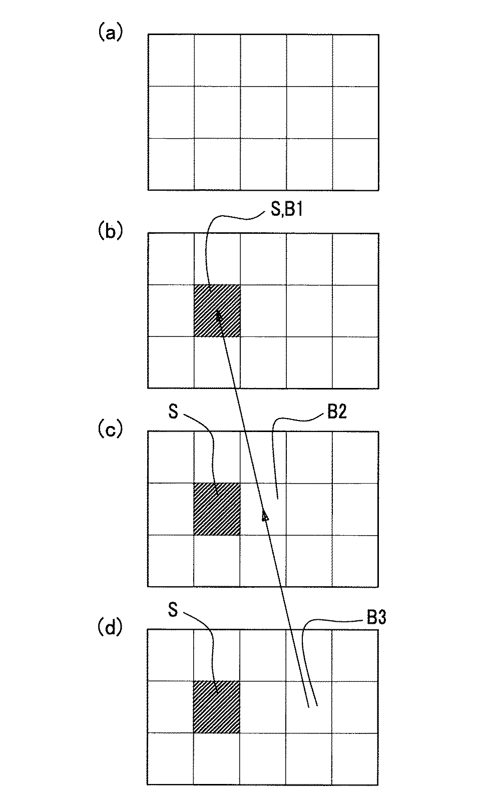
ここで、図7を参照して、特許文献1における問題点について説明する。
図7は、画像全体が(a)、(b)、(c)、(d)の順に右方向へ移動しているパン画像(時系列のフレーム画像)を示している。ここでは、図7(a)に示すように、画像はブロック毎に分割されているものとし、図7(b)の網掛けで示すブロックB1にテロップをスーパーインポーズしたと仮定する(ブロックB1=スーパー領域S)。
【0012】
すると、図7(b)の次のフレーム画像である図7(c)におけるブロックB2は、ブロックB1を動き補償予測における参照画像として符号化される。この場合、特許文献1によれば、ブロックB2は、参照画像がスーパー領域Sに存在するため、他のブロックとは異なる処理(動きベクトルの適応的な切り替え)を行うことで、画質劣化を抑えるようにしている。しかし、再符号化時に量子化を行う一般的な符号化では、元と同じビットストリームを得ることはできず、テロップをスーパーインポーズしていない領域(ブロックB2)においても、画質が劣化してしまうという問題がある。すなわち、再符号化されたブロックB2は、元のビットストリームのブロックB2とは異なる画像となってしまう。
【0013】
また、図7(c)の次のフレーム画像である図7(d)におけるブロックB3は、ブロックB2を動き補償予測における参照画像として符号化される。この場合、特許文献1によれば、ブロックB3はスーパー領域Sに存在せず、ブロックB3が参照する参照画像(ブロックB2)もスーパー領域Sに存在しないため、ブロックB3は、元のビットストリームと同じ画像データであると判定される。そこで、ブロックB3は、ブロックB2を参照画像として符号化が行われる。しかし、ブロックB2は、すでに画質が劣化したブロックであるため、ブロックB3も画質が劣化してしまうという問題がある。すなわち、再符号化されたブロックB3は、元のビットストリームのブロックB3とは異なる画像となってしまう。
【0014】
このように、再符号化時に画質劣化を生じる符号化方式を用いる場合、従来の手法では、スーパーインポーズによって影響を受けるブロックの検出漏れを生じるという問題がある。
【0015】
本発明は、以上のような問題点に鑑みてなされたものであり、映像を符号化した符号化ストリーム(ビットストリーム)に、テロップを合成(スーパーインポーズ)する際に、スーパーインポーズによって影響を受けるブロックを適切に検出し、画質の低減を抑えたテロップ合成符号化ストリーム(ビットストリーム)を生成するテロップ合成装置、テロップ合成方法及びテロップ合成プログラムを提供することを目的とする。
【0016】
【課題を解決するための手段】
本発明は、前記目的を達成するために創案されたものであり、まず、請求項1に記載のテロップ合成装置は、映像を符号化した符号化ストリームに、テロップを合成するテロップ合成装置であって、復号手段と、合成手段と、符号化手段と、比較手段と、切り替え手段と、を備える構成とした。
【0017】
かかる構成によれば、テロップ合成装置は、復号手段によって、入力された符号化ストリームを所定のブロック単位で復号して、復号画像を生成する。ここで、所定のブロックは、1つの画面を構成する画像を細分化したものであって、例えば、MPEG−2、MPEG−4等においては、動き補償の単位となるブロックを用いることができる。そして、テロップ合成装置は、合成手段によって、復号手段で復号された復号画像に、入力されたテロップを合成(スーパーインポーズ)して、合成画像を生成する。このテロップは、文字に限られず、図形、画像、あるいは、他の映像であってもよい。
【0018】
そして、テロップ合成装置は、符号化手段によって、合成手段で合成された合成画像を符号化して、合成画像符号化ストリームを生成する。この合成画像符号化ストリームは、テロップの合成や、再符号化に伴い画質が劣化したものとなっている。
【0019】
そして、テロップ合成装置は、比較手段によって、合成画像と復号画像とを比較して、その比較結果に基づいて、切り替え手段が、符号化ストリームと合成画像符号化ストリームとを切り替えて出力する。すなわち、テロップを合成したことで画質が変化したブロックは、符号化手段で再符号化された合成画像符号化ストリームを出力し、画質が変化していないブロックは、再符号化を行わずに最初に入力された符号化ストリームを出力する。
【0020】
これによって、テロップ合成装置は、画質が変化したブロックを確実に検出することができる。また、テロップ合成装置は、画質が変化しないブロックに対して、再符号化を行わないため、画質の劣化が発生しない。
【0021】
また、請求項2に記載のテロップ合成装置は、請求項1に記載のテロップ合成装置において、前記符号化手段が、前記合成画像をその合成画像内において単独で符号化するイントラモードによって動作することを特徴とする。
【0022】
かかる構成によれば、テロップ合成装置は、符号化手段が、復号画像にテロップを合成した合成画像を符号化する際に、予測符号化を行わず、その合成画像のみで符号化を行う(イントラモード)ことで、符号化における計算量を減らすことができる。
【0023】
さらに、請求項3に記載のテロップ合成装置は、請求項1に記載のテロップ合成装置において、前記切り替え手段から出力されるテロップ合成符号化ストリームを所定のブロック単位で復号して、第二復号画像を生成する第二復号手段を備え、前記符号化手段が、前記第二復号画像を参照して前記合成画像を符号化することを特徴とする。
【0024】
かかる構成によれば、テロップ合成装置は、第二復号手段によって、切り替え手段から出力されるテロップ合成符号化ストリームを復号し、その復号画像を符号化手段が参照することで、符号化手段は予測符号化を行うことができる。これによって、再符号化におけるデータ量の増加を防ぐことができる。
【0025】
また、請求項4に記載のテロップ合成装置は、請求項1乃至請求項3のいずれか1項に記載のテロップ合成装置において、前記符号化手段に、量子化手段と、量子化ステップ変更手段とを備える構成とした。
【0026】
かかる構成によれば、テロップ合成装置は、符号化を行う際に、量子化手段によって、符号化されるデータを離散的な代表値で近似することで量子化を行い、その代表値の間隔、すなわち量子化間隔(量子化ステップ)を量子化ステップ変更手段によって変更する。なお、この量子化ステップを大きく設定することで、符号化量を減らすことができ、量子化ステップを小さく設定することで、画質の劣化を抑えることができる。
【0027】
さらに、請求項5に記載のテロップ合成装置は、請求項1乃至請求項4のいずれか1項に記載のテロップ合成装置において、前記比較手段が、前記合成画像と前記復号画像との類似の度合いを示す類似度が、所定値以上であるときに前記合成画像と前記復号画像とが同一の画像であると判断することを特徴とする。
【0028】
かかる構成によれば、テロップ合成装置は、比較手段が合成画像と復号画像とを比較するときに、合成画像と復号画像との類似度が、所定値以上であるかどうかで判定する。この所定値を高くする、すなわち、一致と判定する類似度を高くすることで、合成画像と復号画像との類似判定が厳しくなる。これによって、切り替え手段は再符号化された合成画像符号化ストリームを出力する割合が高まり符号量は大きくなるが、画質の劣化は小さくなる。ただし、量子化手段で符号量を減らすことで、符号化されたデータ量の増加を抑えることができる。また、所定値を低くする、すなわち、一致と判定する類似度を低くすることでも、符号量を抑えることができる。
【0029】
また、請求項6に記載のテロップ合成方法は、映像を符号化した符号化ストリームに、テロップを合成するテロップ合成方法であって、復号画像生成ステップと、合成画像生成ステップと、比較ステップと、切り替え出力ステップと、を含んでいることを特徴とする。
【0030】
この方法によれば、まず、復号画像生成ステップで、符号化ストリームを所定の画像(ブロック)単位で復号して復号画像を生成する。そして、合成画像生成ステップで、復号画像にテロップを合成して合成画像を生成する。
【0031】
また、テロップ合成方法は、比較ステップで、所定のブロック単位で合成画像と復号画像とを比較する。テロップが合成されているブロックは、復号画像のブロックとは内容が異なっている。そこで、テロップ合成方法は、比較ステップの比較結果に基づいて、切り替え出力ステップで、テロップを合成したことで画質が変化したブロックについては、合成画像を符号化して出力し、テロップを合成したことで画質が変化していないブロックについては、入力された符号化ストリームをそのまま出力する。すなわち、テロップを合成したことで画質が変化しないブロックについては、画質の劣化のないビットストリームが出力されることになる。
【0032】
さらに、請求項7に記載のテロップ合成プログラムは、映像を符号化した符号化ストリームに、テロップを合成するために、コンピュータを、復号手段、合成手段、符号化手段、比較手段、切り替え手段、として機能させることを特徴とする。
【0033】
かかる構成によれば、テロップ合成プログラムは、復号手段によって、符号化ストリームを所定のブロック単位で復号して、復号画像を生成する。そして、合成手段によって、復号手段で復号された復号画像にテロップを合成(スーパーインポーズ)して、合成画像を生成する。
【0034】
そして、テロップ合成プログラムは、符号化手段によって、合成手段で合成された合成画像を符号化して、合成画像符号化ストリームを生成する。この合成画像符号化ストリームは、テロップの合成や、再符号化に伴い画質が劣化したものとなっている。
【0035】
そして、テロップ合成プログラムは、比較手段によって、合成画像と復号画像とを比較して、その比較結果に基づいて、切り替え手段が、符号化ストリームと合成画像符号化ストリームとを切り替えて出力する。すなわち、切り替え手段は、テロップを合成したことで画質が変化したブロックについては、符号化手段で再符号化された合成画像符号化ストリームを出力し、画質が変化していないブロックについては、再符号化を行わずに最初に入力された符号化ストリームを出力する。
【0036】
【発明の実施の形態】
以下、本発明の実施の形態について図面を参照して説明する。
[テロップ合成装置の構成]
図1は、本発明における実施の形態であるテロップ合成装置の構成を示したブロック図である。テロップ合成装置1は、映像を符号化したビットストリーム(符号化ストリーム)に、文字、図形等のテロップを合成したビットストリーム(テロップ合成符号化ストリーム)を生成するものである。ここでは、テロップ合成装置1は、復号手段10(10a、10b及び10c)と、合成手段20と、符号化手段30と、比較手段40と、切り替え手段50とを備えている。
なお、このテロップ合成装置1に入力されるビットストリーム(符号化ストリーム)は、MPEG−2等の予測符号化方式により符号化されているものとする。
【0037】
復号手段10は、ビットストリームを所定のブロック単位で復号して復号画像を出力するものである。例えば、入力されるビットストリームがMPEG−2、MPEG−4等で符号化されたビットストリームの場合、動き補償を行う単位となるブロック(例えば8ライン×8画素)で復号を行う。なお、ここでは、テロップ合成装置1内には、同じ復号機能を有する復号手段10a、復号手段10b及び復号手段10cを備えている。
【0038】
復号手段10aは、テロップ合成装置1に入力されるビットストリームを復号(例えばMPEG−2の復号処理)して、復号画像を生成するものである。ここで復号された復号画像は、合成手段20へ出力される。なお、復号手段10aは、自身が復号した復号画像を参照画像として、動き補償を行うことにより復号を行う。ただし、復号するブロックがイントラブロックである場合は、復号画像の参照は行わない。
【0039】
復号手段10bは、テロップ合成装置1に入力されるビットストリームを復号して、復号画像を生成するものである。ここで復号された復号画像は、比較手段40へ出力される。なお、復号手段10bは、復号手段10cで復号された復号画像を参照画像として、動き補償を行うことにより復号を行う。ただし、復号するブロックがイントラブロックである場合は、復号画像の参照は行わない。
この復号手段10a及び復号手段10bが特許請求の範囲の復号手段に相当する。
【0040】
復号手段10cは、切り替え手段50から出力されるビットストリーム(テロップ合成符号化ストリーム)を復号して、復号画像(第二復号画像)を生成するものである。ここで復号された復号画像は、復号手段10b及び符号化手段30において、動き補償を行うための参照画像として用いられる。
この復号手段10cが特許請求の範囲の第二復号手段に相当する。
【0041】
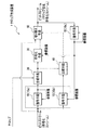
ここで、図2を参照して、復号手段10の詳細な構成について説明する。図2は、予測符号化方式における復号手段10の構成を示すブロック図である。ここでは、復号手段10は、ブロック情報解析部11と、逆量子化部12と、逆DCT部13と、フレームメモリ14と、動き補償部15と、加算部16とを備えている。
【0042】
ブロック情報解析部11は、入力されたビットストリームのブロック情報を解析し、ブロックの動き補償情報と、量子化されたDCT係数(量子化DCT係数)とを抽出するものである。ここで抽出された動き補償情報は、動き補償部15及び加算部16へ通知され、量子化DCT係数は、逆量子化部12へ出力される。
【0043】
ここで、動き補償情報とは、当該ブロックの予測の種類(イントラブロック、片方向予測ブロック、双方向予測ブロック等)、当該ブロックの画像が参照画像に対してどの方向及びどの大きさで動いたかを示す動きベクトル等、当該ブロックを動き補償するために必要となる情報である。
【0044】
また、量子化DCT係数とは、符号化時にブロック毎に離散コサイン変換(DCT:Discrete Cosine Transform)した数(DCT係数)を量子化したものである。なお、このDCT係数の量子化は、DCT係数の値を特定の値で除算して、DCT係数のビット数を低減することで行ったり、予め定めた周波数毎に設定された除数を量子化テーブルとして設定し、その量子化テーブルによって、各周波数におけるDCT係数のビット数を低減することにより行っている。
【0045】
逆量子化部12は、ブロック情報解析部11から出力される量子化DCT係数に対して、逆量子化を行うことで、量子化DCT係数をDCT係数に変換するものである。ここで変換されたDCT係数は、逆DCT部13へ出力される。なお、この量子化DCT係数の逆量子化は、例えば、前記した量子化テーブルと同じテーブルを用い、量子化DCT係数に対して、量子化テーブルの値を乗算することで行う。
【0046】
逆DCT部13は、逆量子化部12で変換されたDCT係数に対して、逆DCT(逆離散コサイン変換)を行うものである。この逆DCTによって生成される画像は、このブロックがイントラブロックである場合は、復号画像そのものであり、イントラブロック以外の場合は、復号画像に対する予測誤差画像となる。ここで生成された画像は加算部16へ出力される。
【0047】
フレームメモリ14は、復号手段10が復号した画像を、次のフレームの復号を行う際の参照画像として蓄積しておくものである。このフレームメモリ14には、1ブロック毎復号されたブロック画像が蓄積され1つのフレーム画像として作成される。そして、現在のフレームを復号するときには、1つ前のフレームを復号したときに作成されたフレーム画像が参照画像として用いられる。
【0048】
動き補償部15は、ブロック情報解析部11から通知される動き補償情報に基づいて、フレームメモリ14に蓄積されている参照画像(1つ前のフレーム画像)から、動きベクトル分動いたと予測される予測画像を生成するものである。この予測画像は、加算部16へ出力される。
【0049】
加算部16は、逆DCT部13から出力される画像(予測誤差画像)と、動き補償部15から出力される予測画像とを加算するものである。この加算された画像が、復号された復号結果画像として復号手段10から出力される。なお、この加算部16は、ブロック情報解析部11から通知されるブロックの予測の種類(動き補償情報)が、イントラブロックである場合は、加算を行わずに、逆DCT部13から出力されるブロック単位の画像(復号画像)をそのまま出力する。
このように、復号手段10を構成することで、ビットストリームを所定のブロック(画像)単位で復号して復号画像を得ることができる。
図1に戻って説明を続ける。
【0050】
合成手段20は、復号手段10aで復号されたブロック単位の復号画像と、そのブロックに対応する位置のテロップ(テロップ信号)とを合成(スーパーインポーズ)して、合成画像を生成するものである。この合成手段20で合成された合成画像は、符号化手段30及び比較手段40へ出力される。なお、合成されるテロップは、文字に限られず、図形、画像、あるいは、他の映像であっても構わない。
【0051】
符号化手段30は、合成手段20で合成された合成画像を符号化して、ビットストリーム(合成画像符号化ストリーム)を生成するものである。なお、この符号化手段30は、合成画像を符号化する際に、復号手段10cで復号された1フレーム前の復号画像(参照画像)を参照して符号化を行う。ここで符号化された合成画像符号化ストリームは、切り替え手段50へ出力される。
【0052】
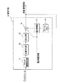
ここで、図3を参照して、符号化手段30の詳細な構成について説明する。図3は、予測符号化方式における符号化手段30の構成を示すブロック図である。ここでは、符号化手段30は、フレームメモリ31と、動き予測部32と、動き補償部33と、減算部34と、DCT部35と、量子化部36と、ブロック情報生成部37とを備えている。
【0053】
フレームメモリ31は、復号手段10が復号した画像を、次のフレームの符号化を行う際の参照画像として蓄積しておくものである。このフレームメモリ31に蓄積された参照画像は、動き予測部32及び動き補償部33によって参照される。なお、このフレームメモリ31に蓄積された参照画像は、復号手段10が1ブロック毎復号したブロック画像をまとめて1つのフレーム画像として作成したものである。そして、現在のフレームを符号化するときには、1つ前のフレーム(フレーム画像)を参照画像として用いる。
【0054】
動き予測部32は、入力された画像(図1の合成手段20が出力する合成画像)と、フレームメモリ31に蓄積されている参照画像とに基づいて、入力画像(合成画像)が参照画像に対してどれくらい動いたかを示すブロック毎の動き予測の方向及び大きさである動きベクトルや、ブロックの予測の種類(イントラブロック、片方向予測ブロック、双方向予測ブロック等)を含んだ動き補償情報を生成するものである。ここで生成された動き補償情報は、動き補償部33、減算部34及びブロック情報生成部37へ通知される。
【0055】
動き補償部33は、動き予測部32で生成された動きベクトルに基づいて、フレームメモリ31に蓄積されている参照画像(例えば、1つ前のフレーム画像)から、動きベクトル分動いたと予測される予測画像を生成するものである。この予測画像は、減算部34へ出力される。
【0056】
減算部34は、符号化手段30に入力された画像(合成画像)と、動き補償部33で生成された予測画像との差分をとった予測誤差画像を生成するものである。この予測誤差画像は、DCT部35に出力される。なお、この減算部34は、動き予測部32から通知されるブロックの予測の種類(動き補償情報)が、イントラブロックである場合は減算を行わずに、入力された画像(合成画像)をブロック単位でそのままDCT部35に出力する。
【0057】
DCT部35は、減算部34から出力される画像を離散コサイン変換(DCT)して、周波数成分の大きさを表すDCT係数を生成するものである。ここで、生成されたDCT係数は、量子化部36に出力される。
【0058】
量子化部(量子化手段)36は、DCT部35で生成されたDCT係数を量子化して、符号量の削減を行うものである。この量子化部36は、DCT係数の中で、視覚感度の低い高周波成分を大きく削減するように予め設定した量子化テーブルに基づいて量子化を行う。また、この量子化部36は、量子化ステップ変更部36aを備えることとした。
【0059】
量子化ステップ変更部36aは、図示していない入力手段から、量子化を行う代表値の間隔(量子化ステップ)を入力されることで、量子化による誤差を調整するものである。例えば、ある周波数における量子化ステップの値を設定している量子化テーブルの数値が「8」(8ビット毎に量子化)であった場合、この数値「8」を除数として量子化が行われ、DCT係数「0」〜「7」は「0」、DCT係数「8」〜「15」は「1」、…という代表値で量子化される。しかし、復号時に、例えば代表値「1」のDCT係数は、8倍されることで、すべて「8」となってしまう。すなわち、量子化前のDCT係数「8」〜「15」は、すべて「8」となってしまい、量子化誤差が発生する。
【0060】
そこで、量子化ステップ変更部36aは、量子化ステップを変更することで符号化手段30の量子化誤差を調整する。例えば、スーパーインポーズに伴う画質の劣化を抑えるには、量子化ステップを小さく設定する。ただし、この場合、符号化結果であるビットストリームのデータ量は増加する。また、量子化ステップを大きく設定すると、画質の劣化は大きくなるがデータ量を抑えることができる。この量子化ステップは、リアルタイムで画質を確認しながら変更してもよいし、すでに使用したことのあるテロップであれば、予めそのテロップによる画質の劣化に適した量子化ステップを設定しておくこととしてもよい。
【0061】
なお、符号化手段30で生成されるビットストリームが使用されるのは、テロップをスーパーインポーズすることで影響されるブロックのみであるので、この量子化ステップ変更部36aで量子化ステップを変更しても、テロップに影響されない画像については、ビットストリームのデータ量の増加や、画質の劣化が生じない。
【0062】
ブロック情報生成部37は、量子化部36で量子化されたDCT係数(量子化DCT係数)、動き予測部32で生成された動き補償情報及びヘッダ情報(例えばMPEG−2におけるシーケンスヘッダ等)から構成されるビットストリーム(合成画像符号化ストリーム)を生成するものである。
このように、符号化手段30を構成することで、合成手段20(図1)で生成されたテロップの合成画像を再符号化することができる。
【0063】
なお、一般的な符号化方式では、最初のフレーム(符号化方式によっては最初のフレームにおける最初のブロック)を必ず予測を用いないモードで符号化すると決められている。そのような符号化方式においては、符号化手段30で最初のフレーム(又は最初のフレームにおける最初のブロック)を再符号化する際には、動き予測部32が定められた予測の種類(例えば、イントラブロック)を動き補償情報として出力する。
【0064】
また、最初のフレーム(又は最初のフレームにおける最初のブロック)に限らず、入力されたフレームが、イントラフレーム(入力されたビットストリームが表すブロックが属しているフレームが予測を用いないモードで符号化されている)の場合は、符号化手段30における再符号化においても、予測を用いないモードで符号化を行うことで、生成されるビットストリームは、入力されたビットストリームと同様にイントラフレームとなる。これによって、生成されたビットストリームは入力されたビットストリームと同様に編集やビットストリームの切り替え等が可能になる。
【0065】
なお、符号化手段30は、参照画像を参照せず、合成手段20で生成された合成画像を、常に予測を用いないモードで符号化(すべてイントラブロックとして符号化)することとしてもよい。これによって、再符号化時の計算量を減らすことができ、実装時の遅延量を小さくすることができる。これは、一般に予測を用いるモードにおける予測の手段としては動き補償予測が用いられるが、この動き補償予測を行うために必要な動き推定は計算量が多いため、実装時における遅延量が大きくなることに起因する。
図1に戻って説明を続ける。
【0066】
比較手段40は、合成手段20で生成された合成画像と、復号手段10bで復号された復号画像とを比較して、その比較結果を切り替え手段50に通知するものである。例えば、比較した結果が一致するときは「真」、一致しないときは「偽」を切り替え手段50に通知する。なお、比較手段40は、図示していない遅延手段を備え、合成手段20から出力される合成画像を遅延させることで、復号画像との同期をとることとする。
【0067】
また、この比較手段40は、合成画像と復号画像との類似度が、所定値以上であるときは、「真」を出力することとしてもよい。この類似の判定は、例えば、2つの画像の距離(画素値の差)によって判定することができる。ここで、あるブロックに含まれる画素の集合をS、画素位置をpとし、比較しようとする2つの画像において、一方の画素値をf(p)、他方の画素値をg(p)で表したとき、(1)式で類似度を判定することができる。
【0068】
【数1】
ここで、比較する閾値Thの値を0にすれば、2つの画像が完全に一致したときのみ、「真」となり、閾値Thの値を大きくすれば、一致と判定する類似度が低くなる。
【0070】
切り替え手段50は、比較手段40から通知される比較結果に基づいて、テロップ合成装置1が入力したビットストリームと、符号化手段30で生成されたビットストリームとをブロック単位で切り替えて、テロップ合成符号化ストリームとして出力するものである。この切り替え手段50では、比較結果が「真」のときは、テロップ合成装置1が入力したビットストリームをそのまま出力する。また、比較結果が「偽」のときは、符号化手段30で生成されたビットストリームを出力する。なお、切り替え手段50は、図示していない遅延手段を備え、符号化手段30で生成されたビットストリームを遅延させることで、テロップ合成装置1が入力したビットストリームとの同期をとることとする。
【0071】
このように、テロップ合成装置1は、映像を符号化した符号化ストリーム(ビットストリーム)にテロップをスーパーインポーズする際に、テロップによって影響される画像(ブロック)を正確に検出することができる。また、テロップによって影響される画像のみを再符号化し、それ以外の画像は入力されたビットストリームをそのまま出力するため、画質の低減を抑えることができる。
【0072】
以上、本発明に係るテロップ合成装置1の構成について説明したが、本発明はこれに限定されるものではない。ここでは、テロップ合成装置1を、予測符号化方式により符号化されたビットストリームにテロップを合成するものとして説明を行ったが、予測符号化が行われていないビットストリームにテロップを合成する場合は、復号手段10及び符号化手段30は、参照画像を参照せずに復号及び符号化を行うこととしてもよい。この場合、テロップ合成装置1から復号手段10cを削除した構成としてもよい。
【0073】
なお、復号手段10及び符号化手段30では、参照画像を1つとし、1フレーム前の参照画像を参照することで、復号及び符号化を行うこととしたが、参照画像を2つ以上用いて、復号及び符号化を行うこととしてもよい。例えば、MPEG−2、MPEG−4等におけるBフレームでは参照画像を2つ用いている。この場合、図2及び図3において、フレームメモリ14及びフレームメモリ31をそれぞれ2つのフレームメモリで構成し、動き補償部15、動き補償部33及び動き予測部32で適切なフレームを参照すればよい。
【0074】
例えば、図5(a)に示すように、フレームメモリ14を2つのフレームメモリ14a及びフレームメモリ14bで構成する。フレームメモリ14aは、復号手段10(図2)が復号した画像を蓄積しておくものであり、1ブロック毎復号されたブロック画像が蓄積されて1つのフレーム画像として作成される。また、フレームメモリ14bは、1フレーム前のフレームメモリ14aの出力を保持するものである。このようにフレームメモリ14を構成すれば、復号手段10は、現在のフレームを復号するときは、フレームメモリ14aを参照することで、1つ前のフレームを復号したときに作成されたフレーム画像を参照画像として得ることができる。また、フレームメモリ14bを参照することで、2つ前のフレームを復号したときに作成されたフレーム画像を参照画像として得ることができる。なお、図5(b)に、フレームメモリ31を2つのフレームメモリ31a及びフレームメモリ31bで構成した例を示すが、図5(a)と構成が同じであるため、説明は省略する。
【0075】
また、例えば、H.264のように参照画像を2つ以上用いる符号化方式の場合であっても、参照画像分のフレームメモリを構成することで本発明を実施することができる。H.264のように、同一フレーム内で予測符号化を行う符号化方式を本発明に適用する場合は、フレームメモリ14及びフレームメモリ31を、1フレーム遅延ではなく、例えば、1ブロック遅延とし、符号化方式の予測に合わせた遅延量のフレームメモリを構成すればよい。
このように、本発明は任意の符号化方式に適用することができる。
【0076】
また、テロップ合成装置1における各機能手段を、コンピュータにおいて機能プログラムとして実現することも可能であり、各機能プログラムを結合して、テロップ合成プログラムとして動作させることも可能である。
【0077】
[テロップ合成装置の動作]
次に、図4を参照(適宜図1、図2及び図3参照)して、テロップ合成装置1の動作について説明する。図4は、テロップ合成装置1の動作を示すフローチャートである。
【0078】
(復号画像生成ステップ)
まず、テロップ合成装置1は、復号手段10a及び復号手段10bによって、映像を符号化したビットストリーム(符号化ストリーム)を、ブロック(例えば8ライン×8画素)単位で復号し、復号画像を生成する(ステップS1)。
【0079】
ここで、復号手段10aは、自身が復号した復号画像を、動き補償を行うための参照画像として参照し、ビットストリームを復号する。一方、復号手段10bは、復号手段10cで復号された復号画像(第二復号画像)を、動き補償を行うための参照画像として参照し、ビットストリームを復号する。ここで、1フレーム内のブロックの復号が終了した段階で、このフレームのフレーム画像がフレームメモリ14に蓄積されることになる。ここで、参照画像を複数用いる符号化方式により復号を行う場合は、フレームメモリ14に複数の参照画像が蓄積されることになる。
なお、復号手段10a及び復号手段10bは、イントラブロックを復号する場合は、参照画像を参照せずに復号を行う。
【0080】
(合成画像生成ステップ)
そして、合成手段20が、復号手段10aで復号されたブロック単位の復号画像と、そのブロックに対応する位置のテロップ(テロップ信号)とを合成して、合成画像を生成する(ステップS2)。
【0081】
(比較ステップ)
そして、比較手段40が、合成手段20で生成された合成画像と、復号手段10bで復号された復号画像とを比較する(ステップS3)。そして、比較手段40は、この比較結果を切り替え手段50に通知する。この比較結果は、比較した結果が一致(同一画像)するときは「真」(例えば、数値「1」)、不一致のときは「偽」(例えば、数値「0」)とする。
なお、この比較手段40における比較は、合成画像と復号手段10bで復号された復号画像との相違量が、予め定めた閾値の範囲内にあるときは、一致の判定を行うこととしてもよい。
【0082】
(切り替え出力ステップ)
比較結果を通知された切り替え手段50は、その比較結果(「真」又は「偽」)に基づいて、出力ストリームを変更する(ステップS4)。ここで、同一画像であると判定した場合(ステップS4でYes)、切り替え手段50は、テロップ合成装置1が入力したビットストリーム(符号化ストリーム)をそのまま出力する(ステップS5)。
【0083】
一方、同一画像でないと判定した場合(ステップS4でNo)、符号化手段30が、合成手段20で合成された合成画像を符号化して、ビットストリーム(合成画像符号化ストリーム)を生成し出力する(ステップS6)。ここで、符号化手段30は、復号手段10cで復号された復号画像(参照画像)を参照して符号化を行う。ただし、参照画像を複数用いる符号化方式により符号化を行うときは、適宜フレームメモリ31に蓄積されているフレーム画像から選択された画像を参照画像として利用する。なお、符号化手段30は、予測を用いないモード(イントラブロック)で合成画像を符号化する場合は、参照画像を参照せずに符号化を行う。
【0084】
(参照画像生成ステップ)
そして、このステップS5及びステップS6で、切り替え手段50によって切り替えられて出力されたビットストリームを、復号手段10cが、復号手段10b及び符号化手段30の参照画像として復号する(ステップS7)。ここで復号された参照画像は、復号手段10bのフレームメモリ14及び符号化手段30のフレームメモリ31に書き込まれ、復号手段10b及び符号化手段30が、予測符号化における復号及び符号化を行う際に参照する。
【0085】
このステップS1からステップS7の動作を、1フレームに含まれるすべてのブロックについての動作させる。ただし、図4のフローチャートでは、1フレーム内のブロックについての動作をステップS1からステップS7で表している。そして、最後に、ビットストリーム(符号化ストリーム)の終了を判定し(ステップS8)、ビットストリームの入力が終了した場合(ステップS8でYes)は、本動作を終了する。一方、ビットストリームが継続している場合(ステップS8でNo)は、ステップS1へ戻って動作を継続する。
【0086】
以上の動作によって、テロップ合成装置1は、映像を符号化した符号化ストリーム(ビットストリーム)にテロップをスーパーインポーズする際に、テロップを合成されることで画質が劣化したブロックについては、再符号化を行い、それ以外のブロックについては、入力されたビットストリーム(符号化ストリーム)をそのまま出力することになり、画質の劣化を抑えることができる。
【0087】
【発明の効果】
以上説明したとおり、本発明に係るテロップ合成装置、テロップ合成方法及びテロップ合成プログラムでは、以下に示す優れた効果を奏する。
【0088】
請求項1、請求項6又は請求項7に記載の発明によれば、映像を符号化したビットストリーム(符号化ストリーム)に、テロップを合成するときに、テロップの合成に起因する画質劣化を伴う画像(ブロック)のみを正確に検出することができる。また、このテロップの合成により画質が劣化した画像(ブロック)のみを再符号化し、それ以外の画像(ブロック)については、元のビットストリームをそのまま出力するため、テロップの合成されたブロック以外は、画質の劣化が発生しない。
【0089】
また、ビットストリームの構造がIBP(Iフレーム、Bフレーム及びPフレーム)構造であっても、1ブロック単位で処理を行うため、処理に伴う遅延量は1ブロック分となり、生放送においても映像にテロップを合成ことが可能になる。
【0090】
請求項2に記載の発明によれば、再符号化時にブロックをイントラブロックとして符号化することで、符号化における計算量が少なくて済み、テロップを合成するときの遅延量を少なくすることができる。
【0091】
請求項3に記載の発明によれば、再符号化時に、ブロックを予測符号化方式により符号化することができるので、符号化されたデータ量を抑えることができる。
【0092】
請求項4に記載の発明によれば、テロップの合成により画質が劣化したブロックにおいて、量子化ステップを小さく設定することで、画質の劣化の程度を軽減することができる。
【0093】
請求項5に記載の発明によれば、映像を符号化したビットストリームに、テロップを合成する際に、画質の劣化とビットストリームの増加量とを調整することができ、例えば、高画質映像のビットストリームにテロップを合成するときは、比較手段における類似判定に用いる類似度を高く設定することで、画質の劣化を抑えることができる。また、低画質映像のビットストリームにテロップを合成するときは、比較手段における類似判定に用いる類似度を低く設定することで、データ量の増加を抑えることができる。
【図面の簡単な説明】
【図1】本発明の実施の形態に係るテロップ合成装置の構成を示すブロック図である。
【図2】本発明の実施の形態に係るテロップ合成装置の復号手段の構成を示すブロック図である。
【図3】本発明の実施の形態に係るテロップ合成装置の符号化手段の構成を示すブロック図である。
【図4】本発明の実施の形態に係るテロップ合成装置の動作を示すフローチャートである。
【図5】本発明の他の実施の形態に係るフレームメモリの構成を示す構成図である。
【図6】映像にテロップを合成する例を示す概念図である。
【図7】従来のテロップ合成手法における問題点を説明するための説明図である。
【符号の説明】
1 テロップ合成装置
10(10a、10b) 復号手段
10(10c) 復号手段(第二復号手段)
11 ブロック情報解析部
12 逆量子化部
13 逆DCT部
14 フレームメモリ
15 動き補償部
16 加算部
20 合成手段
30 符号化手段
31 フレームメモリ
32 動き予測部
33 動き補償部
34 減算部
35 DCT部
36 量子化部(量子化手段)
36a 量子化ステップ変更部(量子化ステップ変更手段)
37 ブロック情報生成部
40 比較手段
50 切り替え手段[0001]
BACKGROUND OF THE INVENTION
The present invention relates to a telop synthesizing device, a telop synthesizing method, and a telop synthesizing program for synthesizing a telop with an encoded video.
[0002]
[Prior art]
Conventionally, as a video (moving image) encoding method, MPEG-2 (ISO / IEC 13818), MPEG-4 (ISO / IEC 14496), H.264 (ITU-T Rec. H.264) and the like are known. Also, an encoded stream (bit stream) of a video encoded by these encoding methods is used for broadcasting or the like. In this case, it may be necessary to synthesize a telop with the encoded video. For example, as shown in FIG. 6, when it is desired to add information such as a weather forecast to a certain video P, the video P is synthesized (superimposed) with a telop T such as a character or a figure, whereby a synthesized video CP Is generated. However, since the telop cannot be synthesized as it is for the encoded video, conventionally, the telop is synthesized by the following procedure.
[0003]
That is, first, the encoded stream is decoded by a decoder. Then, the decoded video is superimposed on the telop, and further, the encoded video is encoded by the encoder (encoder) again by the superimposed video (encoded stream ( Bitstream).
[0004]
However, there is a problem that the image quality is greatly deteriorated when the decoded video is generally encoded again. In order to solve this problem, for example, by performing re-encoding using parameters obtained at the time of decoding such as the number of encoded bits for each macroblock in MPEG-2, picture type, and quantization matrix, image quality can be improved. A technique in which deterioration is reduced is disclosed (for example, see Patent Document 1).
[0005]
[Patent Document 1]
JP 2002-16924 A (paragraph [0028] -paragraph [0066], FIG. 1-11)
[0006]
[Problems to be solved by the invention]
However, the conventional techniques have the following problems.
First, MPEG-2, MPEG-4, H.264. As described above, a general encoding method such as H.264 has a problem that image quality deteriorates when a decoded video is superimposed with a telop and encoded again.
[0007]
Furthermore, MPEG-2, MPEG-4, H.264. H.264 has an IBP structure composed of an I frame using intra coding and a B frame and a P frame using inter coding (however, the B frame and the P frame may not be used). is there). For this reason, when decoding a bit stream (encoded stream) into video and when encoding video as a bit stream, it is necessary to rearrange frames, and in decoding and encoding operations, several frames are required. There is a delay. In addition, when this decoding and encoding is implemented in an apparatus, a delay due to the implementation occurs, and a delay of several frames often occurs.
[0008]
Therefore, a method of decoding a bit stream (encoded stream), superimposing a telop on the decoded video, and further encoding the superimposed video has a frame delay amount. It becomes extremely large and cannot be used as a technique for synthesizing telop with live broadcast video.
[0009]
Further, in the technique disclosed in Patent Document 1 described above, degradation of image quality is reduced by re-encoding the decoded video using parameters obtained at the time of decoding the bit stream. . However, the general coding method only defines the bitstream structure (syntax) and decoding method, and the DCT (Discrete Cosine Transform) transform and quantization control in the encoder are designed depending on the encoder. It is a matter, not a rule. For this reason, it is not possible to obtain the same bit stream as the original at the time of re-encoding only by using the parameters obtained at the time of decoding, and the image quality may deteriorate even in a region where the telop is not superimposed.
[0010]
Furthermore, in the above-mentioned Patent Document 1, both the prediction source image (reference image) used in the predictive encoding method such as MPEG-2 and the encoded image (block image) to be encoded are superimposed. In the case where the image does not exist in the super region where the pause is performed, the re-encoded image is described on the assumption that it is the same as the original bit stream (see paragraph [0055] of Patent Document 1). However, this assumption does not necessarily hold, and there is a problem that image quality deterioration occurs in the peripheral portion of the area where the telop is superimposed.
[0011]
Here, with reference to FIG. 7, the problem in Patent Document 1 will be described.
FIG. 7 shows a pan image (time-series frame image) in which the entire image moves to the right in the order of (a), (b), (c), and (d). Here, as shown in FIG. 7 (a), it is assumed that the image is divided into blocks, and the telop is superimposed on the block B1 indicated by shading in FIG. 7 (b) (block B1). = Super region S).
[0012]
Then, the block B2 in FIG. 7C, which is the next frame image in FIG. 7B, is encoded using the block B1 as a reference image in motion compensation prediction. In this case, according to Patent Document 1, since the reference image is present in the super area S, the block B2 suppresses image quality deterioration by performing processing (adaptive switching of motion vectors) different from other blocks. I am doing so. However, in general coding that performs quantization at the time of re-encoding, the same bit stream as the original cannot be obtained, and the image quality deteriorates even in a region where the telop is not superimposed (block B2). There is a problem of end. That is, the re-encoded block B2 becomes an image different from the block B2 of the original bit stream.
[0013]
Further, the block B3 in FIG. 7D, which is the next frame image of FIG. 7C, is encoded using the block B2 as a reference image in motion compensation prediction. In this case, according to Patent Document 1, the block B3 does not exist in the super region S, and the reference image (block B2) referred to by the block B3 does not exist in the super region S. It is determined that the image data is the same. Therefore, the block B3 is encoded using the block B2 as a reference image. However, since the block B2 is a block whose image quality has already deteriorated, there is a problem that the image quality of the block B3 also deteriorates. That is, the re-encoded block B3 becomes an image different from the block B3 of the original bit stream.
[0014]
As described above, when using an encoding method that causes image quality degradation at the time of re-encoding, there is a problem in that a conventional method causes a detection failure of a block that is affected by superimposition.
[0015]
The present invention has been made in view of the above-described problems. When a telop is combined (superimposed) with an encoded stream (bitstream) obtained by encoding a video, it is influenced by superimposing. An object of the present invention is to provide a telop synthesizing apparatus, a telop synthesizing method, and a telop synthesizing program that appropriately detect a received block and generate a telop synthesis encoded stream (bit stream) with reduced image quality suppressed.
[0016]
[Means for Solving the Problems]
The present invention was created to achieve the above object. First, the telop synthesis apparatus according to claim 1 is a telop synthesis apparatus for synthesizing a telop with an encoded stream obtained by encoding a video. Thus, the decoding unit, the synthesizing unit, the encoding unit, the comparison unit, and the switching unit are provided.
[0017]
According to such a configuration, the telop synthesizing apparatus generates a decoded image by decoding the input encoded stream in units of predetermined blocks by the decoding unit. Here, the predetermined block is obtained by subdividing an image constituting one screen. For example, in MPEG-2, MPEG-4, or the like, a block serving as a unit of motion compensation can be used. Then, the telop synthesizing device synthesizes (superimposes) the input telop with the decoded image decoded by the decoding unit, and generates a synthesized image. This telop is not limited to characters, but may be a figure, an image, or another video.
[0018]
Then, the telop synthesizing apparatus encodes the synthesized image synthesized by the synthesizing unit by the encoding unit to generate a synthesized image encoded stream. This composite image encoded stream has a deteriorated image quality due to the synthesis of telop and re-encoding.
[0019]
Then, the telop synthesizing apparatus compares the synthesized image and the decoded image by the comparison unit, and the switching unit switches between the encoded stream and the synthesized image encoded stream based on the comparison result and outputs the result. That is, a block whose image quality has changed as a result of synthesizing a telop outputs a composite image encoded stream re-encoded by the encoding means, and a block whose image quality has not changed is first re-encoded without being re-encoded. The encoded stream input to is output.
[0020]
Thus, the telop synthesis device can reliably detect a block whose image quality has changed. In addition, since the telop synthesis apparatus does not re-encode a block whose image quality does not change, the image quality does not deteriorate.
[0021]
The telop synthesis apparatus according to claim 2 is the telop synthesis apparatus according to claim 1, wherein the encoding unit operates in an intra mode in which the composite image is encoded independently in the composite image. It is characterized by.
[0022]
According to this configuration, the telop synthesizing apparatus encodes only the synthesized image without performing predictive coding when the encoding unit encodes a synthesized image obtained by synthesizing the telop with the decoded image (intra Mode), the amount of calculation in encoding can be reduced.
[0023]
Furthermore, the telop synthesizing apparatus according to claim 3 is the telop synthesizing apparatus according to claim 1, wherein the telop synthesis encoded stream output from the switching unit is decoded in units of predetermined blocks, and the second decoded image is decoded. Second decoding means for generating the encoded image, wherein the encoding means encodes the synthesized image with reference to the second decoded image.
[0024]
According to such a configuration, the telop synthesis apparatus uses the second decoding unit to decode the telop synthesis encoded stream output from the switching unit, and the encoding unit refers to the decoded image so that the encoding unit predicts. Encoding can be performed. As a result, an increase in the amount of data in re-encoding can be prevented.
[0025]
A telop synthesizing apparatus according to claim 4 is the telop synthesizing apparatus according to any one of claims 1 to 3, wherein the encoding means includes quantization means, quantization step changing means, It was set as the structure provided with.
[0026]
According to such a configuration, the telop synthesizer performs quantization by approximating the data to be encoded with discrete representative values by the quantization means when encoding, and the interval between the representative values, That is, the quantization interval (quantization step) is changed by the quantization step changing means. Note that by setting this quantization step large, the amount of encoding can be reduced, and by setting the quantization step small, deterioration in image quality can be suppressed.
[0027]
Furthermore, the telop synthesis apparatus according to claim 5 is the telop synthesis apparatus according to any one of claims 1 to 4, wherein the comparison unit is configured to determine the degree of similarity between the synthesized image and the decoded image. When the similarity indicating is equal to or greater than a predetermined value, it is determined that the synthesized image and the decoded image are the same image.
[0028]
According to this configuration, the telop synthesizing apparatus determines whether the similarity between the synthesized image and the decoded image is equal to or greater than a predetermined value when the comparison unit compares the synthesized image with the decoded image. By increasing this predetermined value, that is, by increasing the degree of similarity that is determined as coincidence, the similarity determination between the synthesized image and the decoded image becomes severe. As a result, the switching unit increases the ratio of outputting the re-encoded composite image encoded stream and the code amount increases, but the deterioration of the image quality decreases. However, an increase in the amount of encoded data can be suppressed by reducing the amount of code by the quantization means. Also, the code amount can be reduced by lowering the predetermined value, that is, by lowering the degree of similarity determined as coincidence.
[0029]
The telop synthesis method according to claim 6 is a telop synthesis method for synthesizing a telop with an encoded stream obtained by encoding a video, and includes a decoded image generation step, a synthesized image generation step, a comparison step, A switching output step.
[0030]
According to this method, first, in the decoded image generation step, the encoded stream is decoded in units of predetermined images (blocks) to generate a decoded image. Then, in the synthesized image generation step, a telop is synthesized with the decoded image to generate a synthesized image.
[0031]
In the telop composition method, the composite image and the decoded image are compared in a predetermined block unit in the comparison step. The block in which the telop is synthesized has a different content from the block of the decoded image. Therefore, the telop compositing method is based on the comparison result of the comparison step, and for the block whose image quality has changed due to the compositing of the telop in the switching output step, the composite image is encoded and output and the telop is composed For blocks whose image quality has not changed, the input encoded stream is output as it is. That is, for a block whose image quality does not change due to the synthesis of the telop, a bit stream without image quality degradation is output.
[0032]
Furthermore, the telop synthesis program according to claim 7, in order to synthesize a telop with an encoded stream obtained by encoding a video, the computer as a decoding means, a synthesizing means, an encoding means, a comparing means, and a switching means. It is made to function.
[0033]
According to such a configuration, the telop synthesis program generates a decoded image by decoding the encoded stream in predetermined block units by the decoding unit. Then, the synthesizing unit synthesizes (superimposes) the telop with the decoded image decoded by the decoding unit to generate a synthesized image.
[0034]
Then, the telop synthesis program encodes the synthesized image synthesized by the synthesizing unit by the encoding unit to generate a synthesized image encoded stream. This composite image encoded stream has a deteriorated image quality due to the synthesis of telop and re-encoding.
[0035]
Then, the telop synthesis program compares the synthesized image and the decoded image by the comparison unit, and the switching unit switches between the encoded stream and the synthesized image encoded stream based on the comparison result and outputs the result. That is, the switching means outputs the composite image encoded stream re-encoded by the encoding means for the block whose image quality has changed due to the synthesis of the telop, and re-encodes the block whose image quality has not changed. The encoded stream that is input first without output is output.
[0036]
DETAILED DESCRIPTION OF THE INVENTION
Embodiments of the present invention will be described below with reference to the drawings.
[Configuration of telop synthesizer]
FIG. 1 is a block diagram showing a configuration of a telop synthesis apparatus according to an embodiment of the present invention. The telop synthesis apparatus 1 generates a bit stream (telop synthesis coded stream) obtained by synthesizing a telop such as characters and graphics with a bit stream (coded stream) obtained by coding video. Here, the telop synthesis apparatus 1 includes decoding means 10 (10a, 10b, and 10c), synthesis means 20, encoding means 30, comparison means 40, and switching means 50.
It is assumed that the bit stream (encoded stream) input to the telop synthesizer 1 is encoded by a predictive encoding method such as MPEG-2.
[0037]
The
[0038]
The
[0039]
The
The decoding means 10a and the decoding means 10b correspond to the decoding means in the claims.
[0040]
The
This decoding means 10c corresponds to the second decoding means in the claims.
[0041]
Here, a detailed configuration of the
[0042]
The block
[0043]
Here, the motion compensation information is the type of prediction of the block (intra block, unidirectional prediction block, bidirectional prediction block, etc.), and in which direction and in which size the image of the block has moved relative to the reference image. This information is necessary for motion compensation of the block, such as a motion vector indicating.
[0044]
The quantized DCT coefficient is obtained by quantizing the number (DCT coefficient) obtained by performing discrete cosine transform (DCT) for each block during encoding. The quantization of the DCT coefficient is performed by dividing the value of the DCT coefficient by a specific value to reduce the number of bits of the DCT coefficient, or by dividing a divisor set for each predetermined frequency. And the number of bits of the DCT coefficient at each frequency is reduced by the quantization table.
[0045]
The
[0046]
The
[0047]
The
[0048]
Based on the motion compensation information notified from the block
[0049]
The adding
In this way, by configuring the
Returning to FIG. 1, the description will be continued.
[0050]
The synthesizing
[0051]
The
[0052]
Here, the detailed configuration of the encoding means 30 will be described with reference to FIG. FIG. 3 is a block diagram showing the configuration of the encoding means 30 in the predictive encoding method. Here, the encoding means 30 includes a
[0053]
The
[0054]
The
[0055]
Based on the motion vector generated by the
[0056]
The subtracting unit 34 generates a prediction error image obtained by taking the difference between the image (synthesized image) input to the
[0057]
The DCT unit 35 performs a discrete cosine transform (DCT) on the image output from the subtracting unit 34 to generate a DCT coefficient representing the magnitude of the frequency component. Here, the generated DCT coefficient is output to the
[0058]
The quantization unit (quantization means) 36 quantizes the DCT coefficient generated by the DCT unit 35 to reduce the code amount. The
[0059]
The quantization
[0060]
Therefore, the quantization
[0061]
Note that the bit stream generated by the encoding means 30 is used only for blocks that are affected by superimposing the telop, so the quantization
[0062]
The block
In this way, by configuring the
[0063]
In a general encoding method, it is determined that the first frame (the first block in the first frame depending on the encoding method) is necessarily encoded in a mode that does not use prediction. In such an encoding system, when the
[0064]
In addition to the first frame (or the first block in the first frame), the input frame is encoded in a mode in which the intra frame (the frame to which the block represented by the input bitstream belongs does not use prediction). In the case of re-encoding in the
[0065]
Note that the
Returning to FIG. 1, the description will be continued.
[0066]
The
[0067]
Further, the comparison means 40 may output “true” when the similarity between the synthesized image and the decoded image is equal to or greater than a predetermined value. This similarity determination can be made based on, for example, the distance between two images (difference in pixel values). Here, a set of pixels included in a block is S, a pixel position is p, and in two images to be compared, one pixel value is represented by f (p) and the other pixel value is represented by g (p). In this case, the similarity can be determined by the expression (1).
[0068]
[Expression 1]
Here, if the value of the threshold value Th to be compared is set to 0, the result is “true” only when the two images completely match, and if the value of the threshold value Th is increased, the degree of similarity for determining a match is lowered.
[0070]
Based on the comparison result notified from the
[0071]
As described above, the telop synthesizing apparatus 1 can accurately detect an image (block) affected by a telop when the telop is superimposed on an encoded stream (bit stream) obtained by encoding a video. In addition, since only the image affected by the telop is re-encoded and the input bit stream is output as it is for the other images, reduction in image quality can be suppressed.
[0072]
As mentioned above, although the structure of the telop composition apparatus 1 concerning the present invention was explained, the present invention is not limited to this. Here, the telop synthesizing apparatus 1 has been described as synthesizing a telop with a bitstream encoded by the predictive encoding method. However, when synthesizing a telop with a bitstream not subjected to predictive encoding, The
[0073]
In the
[0074]
For example, as shown in FIG. 5A, the
[0075]
Also, for example, H. Even in the case of an encoding method using two or more reference images such as H.264, the present invention can be implemented by configuring a frame memory for reference images. H. When the encoding method for performing predictive encoding within the same frame, such as H.264, is applied to the present invention, the
As described above, the present invention can be applied to any coding scheme.
[0076]
In addition, each functional unit in the telop synthesizing apparatus 1 can be realized as a functional program in a computer, and the respective functional programs can be combined to operate as a telop synthesizing program.
[0077]
[Operation of telop synthesizer]
Next, referring to FIG. 4 (refer to FIGS. 1, 2 and 3 as appropriate), the operation of the telop synthesis apparatus 1 will be described. FIG. 4 is a flowchart showing the operation of the telop synthesis apparatus 1.
[0078]
(Decoded image generation step)
First, the telop synthesizing apparatus 1 decodes a bit stream (encoded stream) obtained by encoding a video in units of blocks (for example, 8 lines × 8 pixels) by the
[0079]
Here, the
Note that the
[0080]
(Composite image generation step)
Then, the synthesizing
[0081]
(Comparison step)
Then, the comparing
The comparison in the
[0082]
(Switching output step)
The switching means 50 notified of the comparison result changes the output stream based on the comparison result (“true” or “false”) (step S4). If it is determined that the images are the same (Yes in step S4), the switching
[0083]
On the other hand, if it is determined that the images are not the same (No in step S4), the
[0084]
(Reference image generation step)
In step S5 and step S6, the
[0085]
The operations from step S1 to step S7 are performed for all the blocks included in one frame. However, in the flowchart of FIG. 4, the operations for the blocks in one frame are represented by steps S1 to S7. Finally, the end of the bit stream (encoded stream) is determined (step S8), and when the input of the bit stream is completed (Yes in step S8), this operation ends. On the other hand, when the bit stream continues (No in step S8), the process returns to step S1 and continues the operation.
[0086]
Through the above operation, the telop synthesizing apparatus 1 re-encodes blocks whose image quality has deteriorated due to the synthesis of the telop when the telop is superimposed on the encoded stream (bit stream) obtained by encoding the video. For other blocks, the input bit stream (encoded stream) is output as it is, and deterioration of image quality can be suppressed.
[0087]
【The invention's effect】
As described above, the telop synthesis apparatus, telop synthesis method, and telop synthesis program according to the present invention have the following excellent effects.
[0088]
According to the first, sixth, or seventh aspect of the present invention, when a telop is combined with a bit stream (encoded stream) obtained by encoding a video, image quality deterioration caused by the combination of the telop is accompanied. Only an image (block) can be detected accurately. In addition, only the image (block) whose image quality has deteriorated due to the synthesis of the telop is re-encoded and the original bit stream is output as it is for the other images (blocks). Degradation of image quality does not occur.
[0089]
Even if the bitstream structure is an IBP (I frame, B frame, and P frame) structure, processing is performed in units of blocks, so the amount of delay associated with the processing is one block, and even in live broadcasts, telop is added to the video. Can be synthesized.
[0090]
According to the second aspect of the present invention, by encoding a block as an intra block at the time of re-encoding, a calculation amount in encoding can be reduced, and a delay amount when synthesizing a telop can be reduced. .
[0091]
According to the invention described in claim 3, since the block can be encoded by the predictive encoding method at the time of re-encoding, the amount of encoded data can be suppressed.
[0092]
According to the fourth aspect of the present invention, the degree of deterioration in image quality can be reduced by setting a small quantization step in a block whose image quality has deteriorated due to the synthesis of telops.
[0093]
According to the fifth aspect of the present invention, when synthesizing a telop with a bitstream obtained by encoding a video, it is possible to adjust the deterioration of the image quality and the amount of increase in the bitstream. When synthesizing a telop with a bitstream, deterioration in image quality can be suppressed by setting a high similarity for use in similarity determination in the comparison means. Further, when a telop is combined with a low-quality video bit stream, an increase in the amount of data can be suppressed by setting the degree of similarity used for similarity determination in the comparison means low.
[Brief description of the drawings]
FIG. 1 is a block diagram showing a configuration of a telop synthesis apparatus according to an embodiment of the present invention.
FIG. 2 is a block diagram showing a configuration of decoding means of the telop synthesis apparatus according to the embodiment of the present invention.
FIG. 3 is a block diagram showing a configuration of encoding means of the telop synthesis apparatus according to the embodiment of the present invention.
FIG. 4 is a flowchart showing an operation of the telop synthesis apparatus according to the embodiment of the present invention.
FIG. 5 is a configuration diagram showing a configuration of a frame memory according to another embodiment of the present invention.
FIG. 6 is a conceptual diagram illustrating an example of synthesizing a telop with a video.
FIG. 7 is an explanatory diagram for explaining a problem in a conventional telop synthesis method.
[Explanation of symbols]
1 Telop synthesizer
10 (10a, 10b) Decoding means
10 (10c) Decoding means (second decoding means)
11 Block information analysis unit
12 Inverse quantization part
13 Reverse DCT section
14 frame memory
15 Motion compensation unit
16 Adder
20 Synthesis means
30 Encoding means
31 frame memory
32 Motion prediction unit
33 Motion compensation unit
34 Subtraction part
35 DCT section
36 Quantization unit (quantization means)
36a Quantization step changing unit (quantization step changing means)
37 Block information generator
40 comparison means
50 switching means
Claims (7)
前記符号化ストリームを所定のブロック単位で復号して、復号画像を生成する復号手段と、
この復号手段で復号された復号画像に前記テロップを合成して、合成画像を生成する合成手段と、
この合成手段で合成された合成画像を符号化して、合成画像符号化ストリームを生成する符号化手段と、
前記合成画像と前記復号画像とを比較する比較手段と、
この比較手段の比較結果に基づいて、前記合成画像と前記復号画像とが同一画像である場合には前記符号化ストリームを、同一画像ではない場合には前記合成画像符号化ストリームを切り替えて、テロップ合成符号化ストリームとして出力する切り替え手段と、
を備えていることを特徴とするテロップ合成装置。A telop synthesis device for synthesizing a telop with an encoded stream obtained by encoding a video,
Decoding means for decoding the encoded stream in predetermined block units to generate a decoded image;
A synthesizing unit for synthesizing the telop with the decoded image decoded by the decoding unit to generate a synthesized image;
An encoding unit that encodes the combined image combined by the combining unit to generate a combined image encoded stream;
Comparing means for comparing the synthesized image and the decoded image;
Based on the comparison result of the comparing means, the encoded stream is switched when the synthesized image and the decoded image are the same image, and the synthesized image encoded stream is switched when the synthesized image is not the same image. Switching means for outputting as a composite encoded stream;
A telop synthesizing apparatus comprising:
前記符号化手段は、前記第二復号画像を参照して前記合成画像を符号化することを特徴とする請求項1に記載のテロップ合成装置。A second decoding unit that generates a second decoded image by decoding the telop synthesis encoded stream output from the switching unit in units of a predetermined block;
The telop synthesis apparatus according to claim 1, wherein the encoding unit encodes the composite image with reference to the second decoded image.
この量子化手段における量子化間隔である量子化ステップを変更する量子化ステップ変更手段と、
を備えていることを特徴とする請求項1乃至請求項3のいずれか1項に記載のテロップ合成装置。The encoding means includes quantization means for quantizing data to be encoded,
A quantization step changing means for changing a quantization step which is a quantization interval in the quantization means;
The telop synthesizing device according to claim 1, wherein the telop synthesizing device is provided.
前記符号化ストリームを所定のブロック単位で復号して、復号画像を生成する復号画像生成ステップと、
この復号画像生成ステップで生成された復号画像に前記テロップを合成して、合成画像を生成する合成画像生成ステップと、
前記合成画像と前記復号画像とを比較する比較ステップと、
この比較ステップの比較結果に基づいて、前記符号化ストリームを出力するか、前記合成画像生成ステップで生成された合成画像を符号化して出力するかを切り替えて実行する切り替え出力ステップと、
を含んでいることを特徴とするテロップ合成方法。A telop synthesis method for synthesizing a telop with an encoded stream obtained by encoding video,
A decoded image generating step of decoding the encoded stream in predetermined block units to generate a decoded image;
A synthesized image generating step of generating a synthesized image by synthesizing the telop with the decoded image generated in the decoded image generating step;
A comparison step of comparing the synthesized image and the decoded image;
A switching output step of switching and executing whether to output the encoded stream or to encode and output the composite image generated in the composite image generation step based on the comparison result of the comparison step;
A telop synthesis method comprising:
前記符号化ストリームを所定のブロック単位で復号して、復号画像を生成する復号手段、
この復号手段で復号された復号画像に前記テロップを合成して、合成画像を生成する合成手段、
この合成手段で合成された合成画像を符号化して、合成画像符号化ストリームを生成する符号化手段、
前記合成画像と前記復号画像とを比較する比較手段、
この比較手段の比較結果に基づいて、前記符号化ストリームと前記合成画像符号化ストリームとを切り替えて、テロップ合成符号化ストリームとして出力する切り替え手段、
として機能させることを特徴とするテロップ合成プログラム。In order to synthesize a telop into an encoded stream obtained by encoding a video,
Decoding means for decoding the encoded stream in predetermined block units to generate a decoded image;
A synthesizing unit for synthesizing the telop with the decoded image decoded by the decoding unit to generate a synthesized image;
Encoding means for encoding a composite image synthesized by the synthesis means to generate a composite image encoded stream;
Comparison means for comparing the synthesized image and the decoded image;
Switching means for switching between the encoded stream and the synthesized image encoded stream based on the comparison result of the comparing means and outputting as a telop synthesized encoded stream;
A telop compositing program characterized in that it functions as
Priority Applications (1)
| Application Number | Priority Date | Filing Date | Title |
|---|---|---|---|
| JP2003144784A JP4133581B2 (en) | 2003-05-22 | 2003-05-22 | Telop synthesis device, telop synthesis method, and telop synthesis program |
Applications Claiming Priority (1)
| Application Number | Priority Date | Filing Date | Title |
|---|---|---|---|
| JP2003144784A JP4133581B2 (en) | 2003-05-22 | 2003-05-22 | Telop synthesis device, telop synthesis method, and telop synthesis program |
Publications (2)
| Publication Number | Publication Date |
|---|---|
| JP2004350030A JP2004350030A (en) | 2004-12-09 |
| JP4133581B2 true JP4133581B2 (en) | 2008-08-13 |
Family
ID=33532148
Family Applications (1)
| Application Number | Title | Priority Date | Filing Date |
|---|---|---|---|
| JP2003144784A Expired - Fee Related JP4133581B2 (en) | 2003-05-22 | 2003-05-22 | Telop synthesis device, telop synthesis method, and telop synthesis program |
Country Status (1)
| Country | Link |
|---|---|
| JP (1) | JP4133581B2 (en) |
Families Citing this family (4)
| Publication number | Priority date | Publication date | Assignee | Title |
|---|---|---|---|---|
| US7839927B2 (en) | 2005-03-24 | 2010-11-23 | Terayon Communication Systems, Inc. | Motion graphics keying in the compressed domain |
| JP2010118936A (en) * | 2008-11-13 | 2010-05-27 | Mitsubishi Electric Corp | Visible watermark embedding device and image restoration apparatus |
| JP5399277B2 (en) * | 2010-01-20 | 2014-01-29 | 株式会社メガチップス | Image compression apparatus, authoring system, and image compression method |
| JP2012199877A (en) * | 2011-03-23 | 2012-10-18 | Sony Corp | Image processing device, image processing method, and program |
-
2003
- 2003-05-22 JP JP2003144784A patent/JP4133581B2/en not_active Expired - Fee Related
Also Published As
| Publication number | Publication date |
|---|---|
| JP2004350030A (en) | 2004-12-09 |
Similar Documents
| Publication | Publication Date | Title |
|---|---|---|
| JP4326743B2 (en) | Transcoding method and transcoder for transcoding predictive-encoded object-based image signal to predictive-encoded block-based image signal | |
| US6625215B1 (en) | Methods and apparatus for context-based inter/intra coding mode selection | |
| US7146056B2 (en) | Efficient spatial scalable compression schemes | |
| KR100964526B1 (en) | Multimedia coding techniques for transitional effects | |
| KR100446083B1 (en) | Apparatus for motion estimation and mode decision and method thereof | |
| KR100643819B1 (en) | Parameterization for fading compensation | |
| JP4159400B2 (en) | Computer-implemented method and recording medium for processing video images | |
| JP5090158B2 (en) | VIDEO INFORMATION RECORDING DEVICE, VIDEO INFORMATION RECORDING METHOD, VIDEO INFORMATION RECORDING PROGRAM, AND RECORDING MEDIUM CONTAINING VIDEO INFORMATION RECORDING PROGRAM | |
| JP4875007B2 (en) | Moving picture coding apparatus, moving picture coding method, and moving picture decoding apparatus | |
| US20080095239A1 (en) | Method for video frame rate conversion | |
| JP2006279573A (en) | Encoder and encoding method, and decoder and decoding method | |
| US20070025438A1 (en) | Elastic storage | |
| JP4133581B2 (en) | Telop synthesis device, telop synthesis method, and telop synthesis program | |
| KR100587274B1 (en) | method for concealing error in MPEG-2 decompression system | |
| JP2010010917A (en) | Dynamic image encoding device, dynamic image decoding device, dynamic image encoding method, and dynamic image decoding method | |
| JP4909592B2 (en) | Moving picture reproduction method, apparatus, and program | |
| JP2005236584A (en) | Moving picture information conversion encoding apparatus | |
| KR100388802B1 (en) | apparatus and method for concealing error | |
| JPH09261632A (en) | Image signal processor | |
| JP4239894B2 (en) | Image encoding apparatus and image decoding apparatus | |
| JP3461280B2 (en) | Moving image editing apparatus and moving image editing method | |
| JP4390009B2 (en) | Encoding apparatus and method, and image processing system | |
| JP2002142225A (en) | Image signal-coding device | |
| KR20080071725A (en) | Method and apparatus for frame error concealment in video decoding | |
| JP2005252870A (en) | Image data processing method and device |
Legal Events
| Date | Code | Title | Description |
|---|---|---|---|
| A621 | Written request for application examination |
Free format text: JAPANESE INTERMEDIATE CODE: A621 Effective date: 20060112 |
|
| A977 | Report on retrieval |
Free format text: JAPANESE INTERMEDIATE CODE: A971007 Effective date: 20071017 |
|
| TRDD | Decision of grant or rejection written | ||
| A01 | Written decision to grant a patent or to grant a registration (utility model) |
Free format text: JAPANESE INTERMEDIATE CODE: A01 Effective date: 20080507 |
|
| A01 | Written decision to grant a patent or to grant a registration (utility model) |
Free format text: JAPANESE INTERMEDIATE CODE: A01 |
|
| A61 | First payment of annual fees (during grant procedure) |
Free format text: JAPANESE INTERMEDIATE CODE: A61 Effective date: 20080602 |
|
| FPAY | Renewal fee payment (event date is renewal date of database) |
Free format text: PAYMENT UNTIL: 20110606 Year of fee payment: 3 |
|
| R150 | Certificate of patent or registration of utility model |
Free format text: JAPANESE INTERMEDIATE CODE: R150 |
|
| FPAY | Renewal fee payment (event date is renewal date of database) |
Free format text: PAYMENT UNTIL: 20110606 Year of fee payment: 3 |
|
| FPAY | Renewal fee payment (event date is renewal date of database) |
Free format text: PAYMENT UNTIL: 20120606 Year of fee payment: 4 |
|
| FPAY | Renewal fee payment (event date is renewal date of database) |
Free format text: PAYMENT UNTIL: 20120606 Year of fee payment: 4 |
|
| FPAY | Renewal fee payment (event date is renewal date of database) |
Free format text: PAYMENT UNTIL: 20130606 Year of fee payment: 5 |
|
| FPAY | Renewal fee payment (event date is renewal date of database) |
Free format text: PAYMENT UNTIL: 20140606 Year of fee payment: 6 |
|
| LAPS | Cancellation because of no payment of annual fees |