JP4133464B2 - Board electrical connector - Google Patents
Board electrical connector Download PDFInfo
- Publication number
- JP4133464B2 JP4133464B2 JP2003062548A JP2003062548A JP4133464B2 JP 4133464 B2 JP4133464 B2 JP 4133464B2 JP 2003062548 A JP2003062548 A JP 2003062548A JP 2003062548 A JP2003062548 A JP 2003062548A JP 4133464 B2 JP4133464 B2 JP 4133464B2
- Authority
- JP
- Japan
- Prior art keywords
- housing
- board
- connector
- type connector
- wiring board
- Prior art date
- Legal status (The legal status is an assumption and is not a legal conclusion. Google has not performed a legal analysis and makes no representation as to the accuracy of the status listed.)
- Expired - Fee Related
Links
Images


Description
【0001】
【発明の属する技術分野】
この発明は、配線基板の表面に取り付けられる基板用電気コネクタに関し、特に、1対の配線基板を電気的に接続するために用いられるボード・トゥ・ボードコネクタに関する。
【0002】
【従来の技術】
従来から、1対の配線基板の表面にそれぞれ取り付けられ、これら1対の配線基板同士の電気的な接続(いわゆるボード・トゥ・ボード接続)を達成するためのボード・トゥ・ボードコネクタが知られている。
ボード・トゥ・ボードコネクタの中には、たとえば、連結凸部を有するプラグ型コネクタと、連結凹部を有するリセプタクル型コネクタとからなり、プラグ型コネクタの連結凸部をリセプタクル型コネクタの連結凹部に嵌合させることにより、それぞれのコネクタのコンタクト(接点)同士が接続され、ボード・トゥ・ボード接続が達成されるようになっているものがある(たとえば、特許文献1参照)。
【0003】
【特許文献1】
特開2000−260509号公報
【0004】
【発明が解決しようとする課題】
近年、各種電気機器(パーソナルコンピュータなど)の小型化が進むにつれて、上記のようなボード・トゥ・ボードコネクタの小型化および薄型化が望まれている。
しかしながら、上記のようなタイプのボード・トゥ・ボードコネクタを薄型化するためには、連結凸部の高さを低くして、連結凹部の深さを浅くしなければならない。1対の配線基板の表面にそれぞれ取り付けられたコネクタ(プラグ型コネクタおよびリセプタクル型コネクタ)をボード・トゥ・ボード接続する場合には、これらの1対のコネクタを互いに擦り合わせるようにして位置合わせを行わなければならないので、連結凸部の高さを低くして、連結凹部の深さを浅くした場合には、連結凹部と連結凸部との当たり部分が小さくなり、位置合わせしにくくなるという問題があった。また、各コネクタを小型化した場合には、位置合わせがさらに困難になる。
【0005】
特に、一方向に長尺の形状を有するコネクタ同士を位置合わせする場合、短手方向の位置合わせを行うときには、長手方向に沿った比較的長い当たり部分に対して位置合わせを行うことができるので、位置合わせが比較的容易である一方、長手方向の位置合わせを行うときには、短手方向に沿った比較的短い当たり部分に対して位置合わせを行わなければならないので、位置合わせが比較的困難であった。
【0006】
この発明は、かかる背景のもとでなされたもので、容易に位置合わせできる基板用電気コネクタを提供することを目的とする。
【0007】
【課題を解決するための手段および発明の効果】
上記目的を達成するための請求項1記載の発明は、配線基板(6)に実装され、相手側コネクタ(5)と嵌合されて電気接続される基板用電気コネクタ(3)であって、上記配線基板と上記相手側コネクタとの電気接続のための接続部(8)と、この接続部を保持する長尺形状のハウジング(10)と、このハウジングの長手方向に沿って長尺に形成され、上記相手側コネクタに形成された環状の連結凸部(21)に嵌合可能な環状の連結凹部(11)と、この連結凹部の内側に設けられ、上記相手側コネクタの上記連結凸部の内側の嵌合凹部(4)と嵌合可能な嵌合凸部(2)と、上記ハウジングの長手方向の少なくとも一端部において、上記ハウジングの上記配線基板とは反対側の表面(ガイド面18)から突出して設けられ、上記相手側コネクタを当該基板用電気コネクタに結合する際に、上記相手側コネクタの端部(突出片27)を受けて、この相手側コネクタの上記長手方向に沿う一方向への変位を規制する規制面(17)を有し、この相手側コネクタと当該基板用電気コネクタとの上記長手方向に関する位置合わせに寄与する位置合わせ突部(12A)とを含み、上記ハウジングは、上記連結凹部の外側に設けられた側面壁(12,13)を有し、この側面壁に上記位置合わせ突部が形成されており、さらに、上記嵌合凸部と上記規制面との間における上記側面壁の上面が、上記相手側コネクタの端部を当接させて上記規制面へとスライドさせるガイド面(18)を構成しており、上記位置合わせ突部の上端の上記配線基板からの高さは、上記ガイド面よりも高く、かつ、上記嵌合凸部の上記配線基板からの高さと一致しており、上記規制面と上記嵌合凸部の端面との間に、上記規制面、上記ガイド面および上記嵌合凸部の端面によって凹部形状の空間が形成されていることを特徴とする基板用電気コネクタである。
【0008】
なお、括弧内の英数字は、後述の実施形態における対応構成要素などを表す。以下、この項において同じ。
この構成によれば、上記基板用電気コネクタと相手側コネクタとをボード・トゥ・ボード接続するために位置合わせする際、各コネクタの短手方向の幅がある程度合うようにして長手方向に相対的に変位させれば、相手側コネクタの端部が基板用電気コネクタの位置合わせ突部の規制面に規制されることとなる。すなわち、相手側コネクタの端部をハウジング側面壁上面のガイド面に当接させて規制面へとスライドさせることによって、相手側コネクタと基板用電気コネクタとの上記長手方向に関する位置合わせを行える。
【0009】
したがって、各コネクタが小型(薄型)のものであって位置合わせが困難な場合でも、長手方向の位置合わせを容易に行うことができる。その後、各コネクタを短手方向に相対的に変位させるだけで短手方向の位置合わせが達成できるので、各コネクタを容易に位置合わせできる。
上記基板用電気コネクタをパーソナルコンピュータなどに適用した場合には、CPUを実装した配線基板(マザーボード)側に当該基板用電気コネクタを取り付けることにより、相手側コネクタが取り付けられた配線基板をマザーボードに対して相対的に変位させて、容易に位置合わせできる。
【0010】
請求項2記載の発明は、上記規制面(17)は、上記ハウジング(10)の短手方向の一端部から他端部まで延びていることを特徴とする請求項1記載の基板用電気コネクタ(3)である。
この構成によれば、規制面をハウジングの短辺に沿って長く(一端部から他端部まで)形成することができるので、基板用電気コネクタと相手側コネクタとを長手方向に相対的に変位させて長手方向の位置合わせを行う場合、相手側コネクタの端部が基板用電気コネクタの規制面に規制されやすい。したがって、位置合わせをより容易に行うことができる。
【0011】
請求項3記載の発明のように、上記接続部(8)は、上記連結凸部と上記連結凹部との嵌合によって、上記配線基板(6)と上記相手側コネクタとを電気的に接続できるように配置されていて、上記位置合わせ突部(12A)は、上記連結凹部よりも上記ハウジングの長手方向端部側に形成されているような構成であれば、連結凹部を有するリセプタクル型コネクタ(基板用電気コネクタ)を、連結凸部を有するプラグ型コネクタ(相手側コネクタ)に対して位置合わせしやすい構造とすることができる。
【0012】
【発明の実施の形態】
以下には、図面を参照して、この発明の実施形態について具体的に説明する。
図1は、この発明の一実施形態に係るボード・トゥ・ボードコネクタ1の外観構成を示す斜視図である。
このボード・トゥ・ボードコネクタ1は、たとえば、連結凹部としての環状凹部11を有するリセプタクル型コネクタ3と、環状凹部11に対応する形状の連結凸部としての環状凸部21を有するプラグ型コネクタ5とを含む。各コネクタ3,5は、たとえば平面視で長方形形状を有していて、それぞれ配線基板6,7(図6参照)の実装面上に半田付けによって実装されて用いられる。
【0013】
リセプタクル型コネクタ3の環状凹部11は、当該リセプタクル型コネクタ3の長手方向に沿って長尺に延びており、その環状凹部11の内側部分を構成する嵌合凸部2の長手方向に沿った両側面2Aからは、それぞれ、プラグ型コネクタ5との電気的な接続を達成するための複数(たとえば、20〜160個ずつ)のコンタクト8が、当該嵌合凸部2の外方に臨んでいる。複数のコンタクト8は、長手方向に沿って等間隔(たとえば、0.3mmピッチ程度)を空けて配置されている。
【0014】
一方、プラグ型コネクタ5の環状凸部21は、当該プラグ型コネクタ5の長手方向に沿って長尺に延びており、その環状凸部21の内側部分を構成する嵌合凹部4の長手方向に沿った両側面4Aからは、それぞれ、リセプタクル型コネクタ3との電気的な接続を達成するための複数(たとえば、20〜120個ずつ)のコンタクト9が、当該嵌合凹部4の内方に臨んでいる。複数のコンタクト9は、嵌合凹部4にリセプタクル型コネクタ3の嵌合凸部2が嵌合したときに、当該嵌合凸部2から外方に臨む複数のコンタクト8と1対1に対向するように、長手方向に沿って等間隔(たとえば、0.3mmピッチ程度)を空けて配置されている。
【0015】
上記のような構成により、リセプタクル型コネクタ3の環状凹部11とプラグ型コネクタ5の環状凸部21とを嵌合させれば、各コネクタ3,5に備えられた複数のコンタクト8,9が互いに当接し、各コネクタ3,5が取り付けられた1対の配線基板6,7同士の電気的な接続(いわゆるボード・トゥ・ボード接続)が達成される。
以下の説明では、各コネクタ3,5に対して配線基板6,7側を下方、各コネクタ3,5に対して配線基板6,7と反対側を上方として説明する。
【0016】
図2は、リセプタクル型コネクタ3の構成を示す図であって、図2(a)は平面図、図2(b)は長辺側から見た正面図、図2(c)は底面図、図2(d)は短辺側から見た側面図をそれぞれ示している。また、図3は、リセプタクル型コネクタ3の断面図であって、図3(a)は図2(a)のA−A線断面図、図3(b)は図2(a)のB−B線断面図をそれぞれ示している。ただし、図2(a)、図2(b)および図2(c)では、リセプタクル型コネクタ3の長手方向の中間部を省略して示している。
【0017】
図1〜図3を参照して、リセプタクル型コネクタ3は、比較的低い高さ(たとえば、約1mm以下)に形成された平面視で略長方形形状(たとえば、短辺が3mm程度、長辺が6〜28mm程度)のハウジング10を備えていて、このハウジング10の上面にほぼ矩形の環状凹部11が形成されることにより、当該環状凹部11の内側に上述した嵌合凸部2が形成されている。環状凹部11の外側には、当該ハウジング10の周縁に沿って側面壁(短辺側側面壁12および長辺側側面壁13)が形成されている。短辺側側面壁12は、たとえば、長辺側側面壁13よりも上方に突出した突出部12Aを有していて、嵌合凸部2の高さと略一致している。
【0018】
嵌合凸部2の長辺側の両側面2Aに沿って配置された複数のコンタクト8は、平面視でハウジング10の短手方向に沿って延びており、互いに平行になるようにハウジング10の長手方向に等間隔を空けて配置されている。各コンタクト8は、たとえば、金属板の打ち抜き加工によって作製されたものであり、ハウジング10の底部を短手方向に延びる基部81と、この基部81の嵌合凸部2側の端部から上方に立ち上がり、嵌合凸部2と反対側に折り返されるように湾曲した形状であって、その先端がプラグ型コネクタ5に対する接点を構成する接点部82と、基部81から下方に突出し、当該コンタクト8を配線基板6の実装面上のランドに半田付けするためのリード部83と、基部81から上方に突出し、当該コンタクト8をハウジング10の長辺側側面壁13に対して下方から圧入するための圧入部84とを有している(図3(a)参照)。接点部82は、たとえば、基部81との結合部を中心にして弾性変形できるようになっている。圧入部84には、たとえば、ハウジング10の長辺側側面壁13に形成された圧入孔14内に当該圧入部84を係止するための係止部841が突設されている。
【0019】
この実施形態では、嵌合凸部2の長辺側の両側面2Aに沿って配置された複数のコンタクト8には、リード部83が基部81の中央部に形成されたコンタクトと、リード部83が基部81の接点部82とは反対側の端部に形成されたコンタクトとの2種類が含まれており、これらが交互に配置されている。このようにリード部83が形成された位置の異なるコンタクト8が交互に配置されることにより、当該リセプタクル型コネクタ3を下方から見た場合に、各コンタクト8のリード部83が長手方向に沿って千鳥状に並ぶようになっている(図2(c)参照)。
【0020】
各コンタクト8の圧入部84をハウジング10の長辺側側面壁13に形成された圧入孔14に対して下方から圧入すると、基部81の底面がハウジング10の底面に沿った状態となり、リード部83がハウジング10の底面から下方に(配線基板6に向かって)突出する(いわゆるスタンドオフタイプ)。当該リセプタクル型コネクタ3を配線基板6に取り付ける場合には、ハウジング10の底面から突出したリード部83と、配線基板6の実装面上のランドとの当接部に半田付けを行うことにより、当該当接部の周囲が半田フィレットで覆われて、リセプタクル型コネクタ3が配線基板6に対して固定される。
【0021】
しかしながら、リセプタクル型コネクタ3をコンタクト8のリード部83だけで配線基板6に固定した場合には、リセプタクル型コネクタ3(リード部83)と配線基板6との接触面積が小さく、形成される半田フィレットも少ない。したがって、当該リセプタクル型コネクタ3に対してプラグ型コネクタ5を抜き差しする際や、配線基板6の表面に沿った方向に外力が作用した場合などに、リセプタクル型コネクタ3が配線基板6に対してはがれやすい。リセプタクル型コネクタ3が配線基板6からはがれてしまうと、接触不良が生じてしまい好ましくない。そこで、ハウジング10の短辺側の両端部には、それぞれ、当該リセプタクル型コネクタ3の配線基板6に対する固定を補強するための補強タブ15が取り付けられている。
【0022】
各補強タブ15は、たとえば、金属板に対して打ち抜き加工および折り曲げ加工することによって作製されたものであり、短辺側側面壁12の一端部から他端部まで延びる基部151と、基部151の両端部から長辺側側面壁13に向かって略直角に折り曲げられた形状の折曲部152と、基部151および折曲部152を連結する結合部154とを備えた略U字状の形状を有している(図2(a)参照)。折曲部152は、たとえば、ハウジング10内(長辺側側面壁13の肉厚内)に収容されている。
【0023】
各補強タブ15の基部151には、底面の中央部から上方に向かって、圧入凹部153が形成されている。各補強タブ15は、ハウジング10の短辺側の両端部に形成された、補強タブの外形に対応する形状の補強タブ収容溝16に上方から挿入される。ハウジング10には、上記補強タブ収容溝16内の中央下部に、圧入凹部153が嵌め込まれて補強タブ15を支持するための補強タブ支持部161が形成されている(図3(b)参照)。補強タブ収容溝16に挿入された補強タブ15は、その圧入凹部153に補強タブ支持部161が圧入されることにより、ハウジング10に対して容易に取り付けられる。圧入凹部153の両側縁には、たとえば、当該圧入凹部153を補強タブ支持部161に係止するための係止部153Aが突設されている。補強タブ15がハウジング10に対して取り付けられた状態では、補強タブ15の上面がハウジング10の長辺側側面壁13の上面に沿った状態となる。
【0024】
各補強タブ15がハウジング10に取り付けられた状態では、各補強タブ15の底部は、圧入凹部153が形成されている部分を除いて、ハウジング10の底面から突出した状態となる。すなわち、補強タブ15の底部が、ハウジング10の底面の4隅から突出し(スタンドオフ)、下方から見るとその角部に沿って略L字状に延びている(図2(c)参照)。基部151、折曲部152および結合部154の底部(ハウジング10から突出した部分)は、それぞれ、第1半田接続縁部151A、第2半田接続縁部152Aおよび第3半田接続縁部154Aを構成していて、これらの第1〜第3半田接続縁部151A,152A,154Aと配線基板6の表面との当接部に半田付けを行うことにより、当該当接部の周囲(第1半田接続縁部151A、第2半田接続縁部152Aおよび第3半田接続縁部154Aの全周)が半田フィレットで覆われて、リセプタクル型コネクタ3の配線基板6に対する固定が補強される。
【0025】
この実施形態では、互いに直交する方向(長手方向および短手方向)に延びる基部151(第1半田接続縁部151A)と折曲部152(第2半田接続縁部152A)とで補強タブ15が配線基板6に半田付けされるので、一方向に延びる平板状の補強タブを配線基板に半田付けする場合と比較して、補強タブ15と配線基板6との接触面積を大きくすることができ、形成される半田フィレットを多くすることができる。したがって、補強タブ15を配線基板6に対してよりはがれにくくすることができる。
【0026】
特に、第1半田接続縁部151Aと第2半田接続縁部152Aとが直交する方向に延びているので、補強タブ15の配線基板6に対するぐらつきを軽減させることができる。したがって、補強タブ15が配線基板6に対してよりはがれにくい。
また、補強タブ15の結合部154(第3半田接続縁部154A)周辺には、真っ直ぐ延びる基部151や折曲部152よりも多くの半田フィレットが形成される。したがって、リセプタクル型コネクタ3が配線基板6に対してさらにはがれにくい構成とすることができる。
【0027】
図4は、プラグ型コネクタ5の構成を示す図であって、図4(a)は平面図、図4(b)は長辺側から見た正面図、図4(c)は底面図、図4(d)は短辺側から見た側面図をそれぞれ示している。また、図5は、プラグ型コネクタ5の断面図であって、図5(a)は図4(a)のC−C線断面図、図5(b)は図4(a)のD−D線断面図をそれぞれ示している。ただし、図4(a)、図4(b)および図4(c)では、プラグ型コネクタ5の長手方向の中間部を省略して示している。
【0028】
図1、図4および図5を参照して、プラグ型コネクタ5は、平面視で略長方形形状(たとえば、短辺が3mm程度、長辺が5〜21mm程度)のハウジング20を備えていて、このハウジング20の上面にほぼ矩形の環状凸部21が形成されることにより、当該環状凸部21の内側に上述した嵌合凹部4が形成されている。プラグ型コネクタ5は、比較的低い高さ(たとえば、約1mm以下)に形成されている。
【0029】
嵌合凹部4の長辺側の両側面4Aに沿って配置された複数のコンタクト9は、平面視でハウジング20の短手方向に沿って延びており、互いに平行になるようにハウジング20の長手方向に等間隔を空けて配置されている。各コンタクト9は、たとえば、金属板の打ち抜き加工によって作製されたものであり、ハウジング20の底部を短手方向に延びる基部91と、この基部91の嵌合凹部4側の端部から上方に真っ直ぐ立ち上がり、その先端がリセプタクル型コネクタ3に対する接点を構成する接点部92と、基部91から下方に突出し、当該コンタクト9を配線基板7の実装面上のランドに半田付けするためのリード部93と、基部91から上方に突出し、当該コンタクト9をハウジング20に対して下方から圧入するための圧入部94とを有している(図5(a)参照)。圧入部94には、たとえば、ハウジング20に形成された圧入孔24内に当該圧入部94を係止するための係止部941が突設されている。
【0030】
この実施形態では、嵌合凹部4の長辺側の両側面4Aに沿って配置された複数のコンタクト9には、リード部93が基部91の接点部92側の端部に形成されたコンタクトと、リード部93が基部91の接点部92とは反対側の端部に形成されたコンタクトとの2種類が含まれており、これらが交互に配置されている。このようにリード部93が形成された位置の異なるコンタクト9が交互に配置されることにより、当該プラグ型コネクタ5を下方から見た場合に、各コンタクト9のリード部93が長手方向に沿って千鳥状に並ぶようになっている(図4(c)参照)。
【0031】
各コンタクト9の圧入部94をハウジング20に形成された圧入孔24に対して下方から圧入すると、基部91の底面がハウジング20の底面に沿った状態となり、リード部93がハウジング20の底面から下方に(配線基板7に向かって)突出する(いわゆるスタンドオフタイプ)。当該プラグ型コネクタ5を配線基板7に取り付ける場合には、ハウジング20の底面から突出したリード部93と、配線基板7の実装面上のランドとの当接部に半田付けを行うことにより、当該当接部の周囲が半田フィレットで覆われて、プラグ型コネクタ5が配線基板7に対して固定される。
【0032】
しかしながら、リセプタクル型コネクタ3の場合と同様に、プラグ型コネクタ5をコンタクト9のリード部93だけで配線基板7に固定した場合には、プラグ型コネクタ5(リード部93)と配線基板7との接触面積が小さく、形成される半田フィレットも少ない。したがって、当該プラグ型コネクタ5をリセプタクル型コネクタ3に対して抜き差しする際や、配線基板7の表面に沿った方向に外力が作用した場合などに、プラグ型コネクタ5が配線基板7に対してはがれやすい。プラグ型コネクタ5が配線基板7からはがれてしまうと、接触不良が生じてしまい好ましくない。そこで、ハウジング20の短辺側の両端部には、それぞれ、当該プラグ型コネクタ5の配線基板7に対する固定を補強するための補強タブ25が取り付けられている。
【0033】
各補強タブ25は、たとえば、金属板に対して打ち抜き加工および折り曲げ加工することによって作製されたものであり、ハウジング20の短辺側両端部の一端部から他端部まで延びる基部251と、基部251の両端部からハウジング20の長手方向中央部に向かって略直角に折り曲げられた形状の折曲部252と、基部251および折曲部252を連結する結合部254とを備えた略U字状の形状を有している(図4(a)参照)。折曲部252は、たとえば、ハウジング20内に収容されている。
【0034】
各補強タブ25の基部251には、底面の中央部から上方に向かって、圧入凹部253が形成されている。各補強タブ25は、ハウジング20の短辺側の両端部に形成された、補強タブ25の外形に対応する形状の補強タブ収容溝26に上方から挿入される。ハウジング20には、上記補強タブ収容溝26内の中央下部に、圧入凹部253が嵌め込まれて補強タブ25を支持するための補強タブ支持部261が形成されている(図5(b)参照)。補強タブ収容溝26に挿入された補強タブ25は、その圧入凹部253に補強タブ支持部261が圧入されることにより、ハウジング20に対して容易に取り付けられる。圧入凹部253の両側縁には、たとえば、当該圧入凹部253を補強タブ支持部261に係止するための係止部253Aが突設されている。補強タブ25がハウジング20に対して取り付けられた状態では、補強タブ25の上面がハウジング20の上面に沿った状態となる。
【0035】
各補強タブ25がハウジング20に取り付けられた状態では、各補強タブ25の底部は、圧入凹部253が形成されている部分を除いて、ハウジング20の底面から突出した状態となる。すなわち、補強タブ25の底部が、ハウジング20の底面の4隅から突出し(スタンドオフ)、下方から見るとその角部に沿って略L字状に延びている(図4(c)参照)。基部251、折曲部252および結合部254の底部(ハウジング20から突出した部分)は、それぞれ、第1半田接続縁部251A、第2半田接続縁部252Aおよび第3半田接続縁部254Aを構成していて、これらの第1〜第3半田接続縁部251A,252A,254Aと配線基板7の表面との当接部に半田付けを行うことにより、当該当接部の周囲(第1半田接続縁部251A、第2半田接続縁部252Aおよび第3半田接続縁部254Aの全周)が半田フィレットで覆われて、プラグ型コネクタ5の配線基板7に対する固定が補強される。
【0036】
この実施形態では、互いに直交する方向(長手方向および短手方向)に延びる基部251(第1半田接続縁部251A)と折曲部252(第2半田接続縁部252A)とで補強タブ25が配線基板7に半田付けされるので、一方向に延びる平板状の補強タブを配線基板に半田付けする場合と比較して、補強タブ25と配線基板7との接触面積を大きくすることができ、形成される半田フィレットを多くすることができる。したがって、補強タブ25を配線基板7に対してよりはがれにくくすることができる。
【0037】
特に、第1半田接続縁部251Aと第2半田接続縁部252Aとが直交する方向に延びているので、補強タブ25の配線基板7に対するぐらつきを軽減させることができる。したがって、補強タブ25が配線基板7に対してよりはがれにくい。
また、補強タブ25の結合部254(第3半田接続縁部254A)周辺には、真っ直ぐ延びる基部251や折曲部252よりも多くの半田フィレットが形成される。したがって、プラグ型コネクタ5が配線基板7に対してさらにはがれにくい構成とすることができる。
【0038】
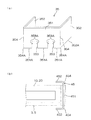
図6は、リセプタクル型コネクタ3とプラグ型コネクタ5とを接続する際の手順の流れを説明するための模式図である。
このボード・トゥ・ボードコネクタ1(リセプタクル型コネクタ3とプラグ型コネクタ5)を接続する場合、作業者は、たとえば、一方の手にリセプタクル型コネクタ3が取り付けられた配線基板6を持ち、他方の手にプラグ型コネクタ5が取り付けられた配線基板7を持って、各配線基板6,7の実装面を互いに対向させた状態から、リセプタクル型コネクタ3の表面(配線基板6と反対側の表面)に対してプラグ型コネクタ5の表面(配線基板7と反対側の表面)を擦り合わせるようにして位置合わせを行う。
【0039】
プラグ型コネクタ5をリセプタクル型コネクタ3に対して位置合わせする場合には、まず、プラグ型コネクタ5をリセプタクル型コネクタ3に対して長手方向に変位させながら、その変位方向奥側の端部を、リセプタクル型コネクタ3の長手方向奥側の端部(突出部12A)に向かって斜めに導く(図6(a)参照)。
プラグ型コネクタ5のハウジング20の長手方向両端部には、当該ハウジング20の短手方向に沿って延びる突出片27が、ハウジング20の上面に対して突出して設けられている。したがって、プラグ型コネクタ5とリセプタクル型コネクタ3との短手方向の幅がある程度合うようにして、プラグ型コネクタ5を上記のようにリセプタクル型コネクタ3側へと導けば、プラグ型コネクタ5の突出片27がリセプタクル型コネクタ3の短辺側側面壁12の上端部に形成された突出部12Aの内側面(規制面17)にぶつかる(規制される)こととなる(図6(b)参照)。
【0040】
プラグ型コネクタ5をリセプタクル型コネクタ3側へと長手方向に導くときには、リセプタクル型コネクタ3の長辺側側面壁13の上面(特に、嵌合凸部2よりも長手方向端部側から規制面17までの部分)は、プラグ型コネクタ5を当接させて規制面17へとスライドさせるためのガイド面18を構成している。このような構成により、リセプタクル型コネクタ3の長手方向両端部には、規制面17と、ガイド面18と、嵌合凸部2の端面とにより、凹部形状の空間が形成されている。規制面17は、ガイド面18に対して略垂直に立ち上がっている。
【0041】
その後、プラグ型コネクタ5の変位方向手前側の端部をリセプタクル型コネクタ3に近づけることにより、プラグ型コネクタ5のハウジング20の表面全体をリセプタクル型コネクタ3のハウジング10の表面全体に当接させる。これにより、プラグ型コネクタ5とリセプタクル型コネクタ3との長手方向の位置合わせが達成される(図6(c)参照)。
この状態からプラグ型コネクタ5をリセプタクル型コネクタ3に対して擦り合わせるようにして短手方向に適当に変位させれば、リセプタクル型コネクタ3の嵌合凸部2の先端部が、プラグ型コネクタ5の環状凸部21内に形成された嵌合凹部4に若干入り込んだ状態となる。これにより、プラグ型コネクタ5とリセプタクル型コネクタ3との短手方向の位置合わせが達成される。短手方向の位置合わせのときには、長手方向に沿った比較的長い当たり部分(嵌合凸部2の両側面2A)に対して位置合わせを行うことができるので、短手方向の位置合わせは比較的容易である。
【0042】
このようにしてリセプタクル型コネクタ3の長手方向および短手方向に対してプラグ型コネクタ5の位置合わせをした後、当該プラグ型コネクタ5(配線基板7)をリセプタクル型コネクタ3側(配線基板6側)に押圧することにより、プラグ型コネクタ5の嵌合凹部4とリセプタクル型コネクタ3の嵌合凸部2とを嵌合させ、リセプタクル型コネクタ3とプラグ型コネクタ5とをしっかりと接続することができる。
【0043】
この実施形態では、1対の配線基板6,7を電気的に接続(ボード・トゥ・ボード接続)するに際して、リセプタクル型コネクタ3とプラグ型コネクタ5とを位置合わせする場合、各コネクタ3,5の短手方向の幅がある程度合うようにして長手方向に相対的に変位させれば、プラグ型コネクタ5の端部(突出片27)がリセプタクル型コネクタ3の規制面17に規制されることとなる。
したがって、各コネクタ3,5が小型(薄型)のものであって位置合わせが困難な場合でも、長手方向の位置合わせを容易に行うことができる。その後、プラグ型コネクタ5を短手方向に変位させるだけで短手方向の位置合わせが達成できるので、各コネクタ3,5を容易に位置合わせできる。
【0044】
当該ボード・トゥ・ボードコネクタ1をパーソナルコンピュータなどに適用した場合には、CPUを実装した配線基板(マザーボード)側にリセプタクル型コネクタ3を取り付けることにより、プラグ型コネクタ5が取り付けられた配線基板7をマザーボード(配線基板6)に対して相対的に変位させて、容易に位置合わせを行うことができる。
ただし、上記のような構成に限らず、マザーボード側にプラグ型コネクタ5を取り付けた場合のように、プラグ型コネクタ5に対してリセプタクル型コネクタ3を変位させて取り付けるような構成であっても、リセプタクル型コネクタ3の規制面17がプラグ型コネクタ5の規制面17に規制されるように変位させれば、容易に位置合わせを行うことができる。
【0045】
また、この実施形態では、規制面17がハウジング10の短辺に沿って長く(一端部から他端部まで)形成されているので、プラグ型コネクタ5をリセプタクル型コネクタ3に対して長手方向に位置合わせする場合、プラグ型コネクタ5の突出片27がリセプタクル型コネクタ3の規制面17に規制されやすい。したがって、位置合わせをより容易に行うことができる。
上記実施形態では、突出片27がプラグ型コネクタ5のハウジング20の長手方向両端部に形成された構成について説明したが、ハウジング20の長手方向の一方側端部(変位方向奥側の端部)にのみ設けられたような構成であってもよい。
【0046】
また、突出片27を設けずに、たとえば、プラグ型コネクタ5のハウジング20の端部(短辺側の端面)をリセプタクル型コネクタ3の規制面17で規制するような構成であってもよい。
図7は、補強タブ15,25の変形例を示す概略図であって、図7(a)は第1変形例に係る補強タブ35の概略斜視図、図7(b)は第2変形例に係る補強タブ45の取り付け態様を示す概略平面図をそれぞれ示している。なお、図7(b)では、コネクタ3,5の一部を省略して示している。
【0047】
図7(a)および図7(b)に示す補強タブ35,45は、たとえば、金属板に対して打ち抜き加工および折り曲げ加工することによって作製されたものであり、上記実施形態に係る補強タブ15,25と同様に、コネクタ(リセプタクル型コネクタ3またはプラグ型コネクタ5)の短辺側端部に配置され、当該コネクタ3,5の短手方向の一端部から他端部まで延びる基部351,451と、基部351,451の両端部からコネクタ3,5の長手方向中央部に向かって略直角に折り曲げられた形状の折曲部352,452と、基部351,451および折曲部352,452を連結する結合部354,454とを備えた略U字状の形状を有している。
【0048】
図7(a)に示す第1変形例に係る補強タブ35は、基部351の底面の中央部から上方に向かって、同様の構成を有する2つの圧入凹部353が所定間隔を空けて形成されている点に特徴がある。コネクタ3,5のハウジング10,20に上記2つの圧入凹部353に対応する2つの補強タブ支持部を設けて、これらの補強タブ支持部に圧入凹部353を圧入することにより、配線基板6,7に対して半田付けされる補強タブ35に対して、ハウジング10,20をより安定して取り付けることができる。各圧入凹部353の両側縁には、たとえば、当該圧入凹部353を対応する補強タブ支持部に係止するための係止部353Aが突設されている。
【0049】
この場合でも、補強タブ35がハウジング10,20に取り付けられた状態では、補強タブ35の底部は、2つの圧入凹部353が形成されている部分を除いて、ハウジング10,20の底面から突出した状態となり、これらの突出した部分(基部351の底部(第1半田接続縁部351A)、折曲部352の底部(第2半田接続縁部352A)、結合部354の底部(第3半田接続縁部354A))と配線基板6,7の表面との当接部に半田付けを行えば、十分な強度で補強タブ35を配線基板6,7に対して固定することができる。
【0050】
このように、補強タブに形成される圧入凹部は、1つに限らず、複数個であってもよい。圧入凹部を複数個形成すれば、補強タブとハウジング10,20との一体性が増し、より強度が向上する。
図7(b)に示す第2変形例に係る補強タブ45は、基部451の両端部がコネクタ3,5のハウジング10,20から短手方向に突出しており、各折曲部452がハウジング10,20の外部に位置している点に特徴がある。このように補強タブ45の基部451を延長すれば、補強タブ45と配線基板6,7との接触面積をさらに大きくすることができ、形成される半田フィレットをさらに多くすることができるので、コネクタ3,5が配線基板6,7に対してさらにはがれにくい構成とすることができる。
【0051】
上記実施形態では、補強タブ15,25がコネクタ3,5のハウジング10,20に対して上方から圧入されるような構成について説明したが、コネクタ3,5のハウジング10,20に対して下方から圧入されるような構成であってもよい。
この発明は、以上の実施形態の内容に限定されるものではなく、請求項記載の範囲内において種々の変更が可能である。
【図面の簡単な説明】
【図1】この発明の一実施形態に係るボード・トゥ・ボードコネクタの外観構成を示す斜視図である。
【図2】リセプタクル型コネクタの構成を示す図であって、図2(a)は平面図、図2(b)は長辺側から見た正面図、図2(c)は底面図、図2(d)は短辺側から見た側面図をそれぞれ示している。
【図3】図3は、リセプタクル型コネクタの断面図であって、図3(a)は図2(a)のA−A線断面図、図3(b)は図2(a)のB−B線断面図をそれぞれ示している。
【図4】プラグ型コネクタの構成を示す図であって、図4(a)は平面図、図4(b)は長辺側から見た正面図、図4(c)は底面図、図4(d)は短辺側から見た側面図をそれぞれ示している。
【図5】プラグ型コネクタの断面図であって、図5(a)は図4(a)のC−C線断面図、図5(b)は図4(a)のD−D線断面図をそれぞれ示している。
【図6】リセプタクル型コネクタとプラグ型コネクタとを接続する際の手順の流れを説明するための模式図である。
【図7】補強タブの変形例を示す概略図であって、図7(a)は第1変形例に係る補強タブの概略斜視図、図7(b)は第2変形例に係る補強タブの取り付け態様を示す概略平面図をそれぞれ示している。
【符号の説明】
3 リセプタクル型コネクタ
5 プラグ型コネクタ
6 配線基板
8 コンタクト
10 ハウジング
11 環状凹部
12A 突出部
17 規制面
18 ガイド面
21 環状凸部
27 突出片[0001]
BACKGROUND OF THE INVENTION
The present invention relates to a board electrical connector attached to the surface of a wiring board, and more particularly to a board-to-board connector used to electrically connect a pair of wiring boards.
[0002]
[Prior art]
Conventionally, there has been known a board-to-board connector that is attached to the surface of a pair of wiring boards and achieves electrical connection (so-called board-to-board connection) between the pair of wiring boards. ing.
The board-to-board connector includes, for example, a plug-type connector having a connection convex portion and a receptacle-type connector having a connection concave portion, and the connection convex portion of the plug-type connector is fitted into the connection concave portion of the receptacle-type connector. In some cases, the contacts (contacts) of the respective connectors are connected to each other so that board-to-board connection is achieved (for example, see Patent Document 1).
[0003]
[Patent Document 1]
JP 2000-260509 A
[0004]
[Problems to be solved by the invention]
In recent years, as various electric devices (such as personal computers) have been miniaturized, it is desired to reduce the size and thickness of the board-to-board connector as described above.
However, in order to make a board-to-board connector of the type described above thinner, it is necessary to reduce the height of the connecting projection and reduce the depth of the connecting recess. When board-to-board connectors (plug-type connectors and receptacle-type connectors) attached to the surface of a pair of wiring boards are aligned with each other by rubbing the pair of connectors together. Since the height of the connecting convex portion is lowered and the depth of the connecting concave portion is made shallow, the contact portion between the connecting concave portion and the connecting convex portion becomes small, and it is difficult to align. was there. Moreover, when each connector is reduced in size, alignment becomes more difficult.
[0005]
In particular, when aligning connectors having long shapes in one direction, when aligning in the short direction, it is possible to align the relatively long contact portion along the longitudinal direction. While the alignment is relatively easy, the alignment in the longitudinal direction is relatively difficult because the alignment must be performed with respect to the relatively short contact portion along the short direction. there were.
[0006]
The present invention has been made under such a background, and an object thereof is to provide an electrical connector for a board that can be easily aligned.
[0007]
[Means for Solving the Problems and Effects of the Invention]
The invention according to
[0008]
The alphanumeric characters in parentheses indicate corresponding components in the embodiments described later. The same applies hereinafter.
According to this configuration, when the board electrical connector and the mating connector are aligned for board-to-board connection, the width in the short direction of each connector is matched to some extent, and the relative position in the longitudinal direction is relative. If it is displaced to, the end of the mating connector will be regulated by the regulating surface of the alignment projection of the board electrical connector.That is, by aligning the end of the mating connector with the guide surface on the upper surface of the side wall of the housing and sliding it to the regulating surface, the mating connector and the board electrical connector can be aligned in the longitudinal direction.
[0009]
Therefore, even when each connector is small (thin) and alignment is difficult, alignment in the longitudinal direction can be easily performed. After that, since the alignment in the short direction can be achieved only by relatively displacing each connector in the short direction, each connector can be easily aligned.
When the board electrical connector is applied to a personal computer or the like, the board electrical connector is attached to the wiring board (motherboard) side on which the CPU is mounted, so that the wiring board to which the counterpart connector is attached is connected to the motherboard. And can be easily aligned.
[0010]
The invention according to
According to this configuration, since the restriction surface can be formed long (from one end to the other end) along the short side of the housing, the board electrical connector and the mating connector are relatively displaced in the longitudinal direction. When the alignment in the longitudinal direction is performed, the end portion of the mating connector is easily regulated by the regulation surface of the board electrical connector. Therefore, alignment can be performed more easily.
[0011]
Like invention of
[0012]
DETAILED DESCRIPTION OF THE INVENTION
Embodiments of the present invention will be specifically described below with reference to the drawings.
FIG. 1 is a perspective view showing an external configuration of a board-to-
The board-to-
[0013]
The
[0014]
On the other hand, the
[0015]
When the
In the following description, the side of the
[0016]
2A and 2B are diagrams showing the configuration of the receptacle-
[0017]
1 to 3, the receptacle-
[0018]
The plurality of
[0019]
In this embodiment, the plurality of
[0020]
When the press-
[0021]
However, when the
[0022]
Each reinforcing
[0023]
A press-
[0024]
In a state where each reinforcing
[0025]
In this embodiment, the reinforcing
[0026]
In particular, since the first
Further, more solder fillets are formed around the joint portion 154 (third solder
[0027]
4A and 4B are diagrams showing the configuration of the plug-
[0028]
1, 4 and 5, the plug-
[0029]
The plurality of
[0030]
In this embodiment, the plurality of
[0031]
When the press-
[0032]
However, as in the case of the receptacle-
[0033]
Each reinforcing
[0034]
A press-
[0035]
In a state where each reinforcing
[0036]
In this embodiment, the reinforcing
[0037]
In particular, since the first
Further, more solder fillets are formed around the joint portion 254 (third solder
[0038]
FIG. 6 is a schematic diagram for explaining a procedure flow when connecting the
When connecting this board-to-board connector 1 (
[0039]
When positioning the plug-
At both ends in the longitudinal direction of the
[0040]
When the plug-
[0041]
Thereafter, the entire front surface of the
If the plug-
[0042]
After the plug-
[0043]
In this embodiment, when the receptacle-
Therefore, even when the
[0044]
When the board-to-
However, the present invention is not limited to the above-described configuration, and even when the plug-
[0045]
In this embodiment, the restricting
In the above embodiment, the configuration in which the protruding
[0046]
Further, for example, the configuration may be such that the end portion (the end surface on the short side) of the
FIG. 7 is a schematic view showing a modified example of the reinforcing
[0047]
The reinforcing
[0048]
The reinforcing
[0049]
Even in this case, when the reinforcing
[0050]
Thus, the press-fitting recess formed in the reinforcing tab is not limited to one, but may be a plurality. If a plurality of press-fitting recesses are formed, the integrity between the reinforcing tab and the
In the reinforcing
[0051]
In the above-described embodiment, the configuration in which the reinforcing
The present invention is not limited to the contents of the above embodiments, and various modifications can be made within the scope of the claims.
[Brief description of the drawings]
FIG. 1 is a perspective view showing an external configuration of a board-to-board connector according to an embodiment of the present invention.
2A and 2B are diagrams showing a configuration of a receptacle-type connector, in which FIG. 2A is a plan view, FIG. 2B is a front view seen from the long side, and FIG. 2C is a bottom view; 2 (d) shows side views as seen from the short side.
3 is a cross-sectional view of a receptacle type connector, FIG. 3 (a) is a cross-sectional view taken along the line AA of FIG. 2 (a), and FIG. 3 (b) is a cross-sectional view of FIG. -B line sectional drawing is shown, respectively.
4A and 4B are diagrams illustrating a configuration of a plug-type connector, in which FIG. 4A is a plan view, FIG. 4B is a front view as viewed from the long side, and FIG. 4C is a bottom view. 4 (d) shows side views as seen from the short side.
5A and 5B are cross-sectional views of the plug-type connector, in which FIG. 5A is a cross-sectional view taken along the line CC in FIG. 4A, and FIG. 5B is a cross-sectional view taken along the line DD in FIG. Each figure is shown.
FIG. 6 is a schematic diagram for explaining the flow of procedures when connecting the receptacle-type connector and the plug-type connector.
7A and 7B are schematic views showing a modified example of the reinforcing tab, wherein FIG. 7A is a schematic perspective view of the reinforcing tab according to the first modified example, and FIG. 7B is a reinforcing tab according to the second modified example. The schematic plan view which shows the attachment aspect of each is shown.
[Explanation of symbols]
3 Receptacle connector
5 Plug type connector
6 Wiring board
8 Contact
10 Housing
11 annular recess
12A Protrusion
17 Regulatory aspects
18 Guide surface
21 Annular projection
27 Protruding piece
Claims (3)
上記配線基板と上記相手側コネクタとの電気接続のための接続部と、
この接続部を保持する長尺形状のハウジングと、
このハウジングの長手方向に沿って長尺に形成され、上記相手側コネクタに形成された環状の連結凸部に嵌合可能な環状の連結凹部と、
この連結凹部の内側に設けられ、上記相手側コネクタの上記連結凸部の内側の嵌合凹部と嵌合可能な嵌合凸部と、
上記ハウジングの長手方向の少なくとも一端部において、上記ハウジングの上記配線基板とは反対側の表面から突出して設けられ、上記相手側コネクタを当該基板用電気コネクタに結合する際に、上記相手側コネクタの端部を受けて、この相手側コネクタの上記長手方向に沿う一方向への変位を規制する規制面を有し、この相手側コネクタと当該基板用電気コネクタとの上記長手方向に関する位置合わせに寄与する位置合わせ突部とを含み、
上記ハウジングは、上記連結凹部の外側に設けられた側面壁を有し、この側面壁に上記位置合わせ突部が形成されており、さらに、上記嵌合凸部と上記規制面との間における上記側面壁の上面が、上記相手側コネクタの端部を当接させて上記規制面へとスライドさせるガイド面を構成しており、
上記位置合わせ突部の上端の上記配線基板からの高さは、上記ガイド面よりも高く、かつ、上記嵌合凸部の上記配線基板からの高さと一致しており、
上記規制面と上記嵌合凸部の端面との間に、上記規制面、上記ガイド面および上記嵌合凸部の端面によって凹部形状の空間が形成されていることを特徴とする基板用電気コネクタ。An electrical connector for a board that is mounted on a wiring board and is electrically connected to a mating connector,
A connecting portion for electrical connection between the wiring board and the mating connector;
A long-shaped housing for holding the connecting portion;
An annular connecting recess that is elongated along the longitudinal direction of the housing and can be fitted into an annular connecting protrusion formed on the mating connector;
A fitting convex portion provided inside the coupling concave portion and capable of fitting with a fitting concave portion inside the coupling convex portion of the mating connector;
In at least one end portion in the longitudinal direction of the housing, and the wiring board of the housing protrudes from the surface opposite, when coupling the mating connector to the electrical connector for the board, the mating connector Receiving the end, it has a regulating surface that regulates the displacement of the mating connector in one direction along the longitudinal direction, and contributes to the alignment of the mating connector and the board electrical connector in the longitudinal direction. the alignment projection to only including,
The housing has a side wall provided outside the coupling recess, the alignment projection is formed on the side wall, and the housing between the fitting projection and the regulation surface The upper surface of the side wall constitutes a guide surface that abuts the end of the mating connector and slides to the regulating surface,
The height of the upper end of the alignment protrusion from the wiring board is higher than the guide surface, and coincides with the height of the fitting protrusion from the wiring board,
A board- shaped electrical connector characterized in that a recess-shaped space is formed between the regulation surface and the end surface of the fitting projection by the regulation surface, the guide surface, and the end surface of the fitting projection. .
上記位置合わせ突部は、上記連結凹部よりも上記ハウジングの長手方向端部側に形成されていることを特徴とする請求項1または2記載の基板用電気コネクタ。 The connecting part is arranged so that the wiring board and the mating connector can be electrically connected by fitting the connecting convex part and the connecting concave part,
3. The board electrical connector according to claim 1, wherein the alignment protrusion is formed closer to a longitudinal end of the housing than the connection recess. 4.
Priority Applications (1)
| Application Number | Priority Date | Filing Date | Title |
|---|---|---|---|
| JP2003062548A JP4133464B2 (en) | 2003-03-07 | 2003-03-07 | Board electrical connector |
Applications Claiming Priority (1)
| Application Number | Priority Date | Filing Date | Title |
|---|---|---|---|
| JP2003062548A JP4133464B2 (en) | 2003-03-07 | 2003-03-07 | Board electrical connector |
Publications (2)
| Publication Number | Publication Date |
|---|---|
| JP2004273277A JP2004273277A (en) | 2004-09-30 |
| JP4133464B2 true JP4133464B2 (en) | 2008-08-13 |
Family
ID=33124389
Family Applications (1)
| Application Number | Title | Priority Date | Filing Date |
|---|---|---|---|
| JP2003062548A Expired - Fee Related JP4133464B2 (en) | 2003-03-07 | 2003-03-07 | Board electrical connector |
Country Status (1)
| Country | Link |
|---|---|
| JP (1) | JP4133464B2 (en) |
Families Citing this family (8)
| Publication number | Priority date | Publication date | Assignee | Title |
|---|---|---|---|---|
| US6811411B1 (en) | 2003-09-12 | 2004-11-02 | Molex Incorporated | Board-to-board electrical connector assembly |
| JP2006164594A (en) * | 2004-12-03 | 2006-06-22 | Molex Inc | Substrate-to-substrate connector |
| JP4723308B2 (en) * | 2005-08-04 | 2011-07-13 | 日本圧着端子製造株式会社 | Electrical connector |
| JP5815277B2 (en) * | 2011-05-13 | 2015-11-17 | 第一電子工業株式会社 | Electrical connector |
| KR20150084563A (en) | 2014-01-14 | 2015-07-22 | 삼성디스플레이 주식회사 | Connector assembly and display apparatus having the same |
| KR102525442B1 (en) * | 2020-05-13 | 2023-04-26 | 니혼 고꾸 덴시 고교 가부시끼가이샤 | Connector assembly |
| JP7461245B2 (en) | 2020-08-05 | 2024-04-03 | 日本航空電子工業株式会社 | connector |
| KR20220136987A (en) | 2021-03-29 | 2022-10-11 | 선전 야치 테크놀로지 컴퍼니 리미티드 | Ultra-small spacing base head, connector, electronic device and manufacturing method of base head |
-
2003
- 2003-03-07 JP JP2003062548A patent/JP4133464B2/en not_active Expired - Fee Related
Also Published As
| Publication number | Publication date |
|---|---|
| JP2004273277A (en) | 2004-09-30 |
Similar Documents
| Publication | Publication Date | Title |
|---|---|---|
| JP4425058B2 (en) | Contact structure and electrical connector using the same | |
| JP5603790B2 (en) | Floating connector | |
| JP2007172940A (en) | Electric connector | |
| JP4851510B2 (en) | Electrical connector | |
| JP2001006771A (en) | Connector | |
| JP2008210616A (en) | Electrical connector for circuit board, and combination connector having the same | |
| JP2007220327A (en) | Floating type connector | |
| US9130322B2 (en) | Electrical connector assembly with an adapter assembled thereof | |
| KR101255371B1 (en) | Electric connector for substrate | |
| JP2001273949A (en) | Electric connector | |
| JP4133464B2 (en) | Board electrical connector | |
| JP6655797B2 (en) | Connectors, headers and sockets | |
| JP2014191882A (en) | Electric connector | |
| JP5523776B2 (en) | Electrical connectors and connectors | |
| JP2007042384A (en) | Electric connector | |
| CN110277680B (en) | Plug, socket and connector | |
| JP5203099B2 (en) | Vertical SMT connector | |
| JP4116503B2 (en) | Board to board connector | |
| JP2004527069A (en) | Small board-to-board connector | |
| JP2006012625A (en) | Board to board connector | |
| JP2001052788A (en) | Electric connector device between fpc and printed circuit board | |
| JP2004273278A (en) | Reinforcing tab and electric connector for base board using the same | |
| JP4353932B2 (en) | Electrical connector with ground plate | |
| JP4852469B2 (en) | Card edge connector | |
| JP3293052B2 (en) | Electrical connector for surface mounting |
Legal Events
| Date | Code | Title | Description |
|---|---|---|---|
| A621 | Written request for application examination |
Free format text: JAPANESE INTERMEDIATE CODE: A621 Effective date: 20060209 |
|
| A977 | Report on retrieval |
Free format text: JAPANESE INTERMEDIATE CODE: A971007 Effective date: 20080207 |
|
| A131 | Notification of reasons for refusal |
Free format text: JAPANESE INTERMEDIATE CODE: A131 Effective date: 20080219 |
|
| A521 | Written amendment |
Free format text: JAPANESE INTERMEDIATE CODE: A523 Effective date: 20080418 |
|
| TRDD | Decision of grant or rejection written | ||
| A01 | Written decision to grant a patent or to grant a registration (utility model) |
Free format text: JAPANESE INTERMEDIATE CODE: A01 Effective date: 20080520 |
|
| A01 | Written decision to grant a patent or to grant a registration (utility model) |
Free format text: JAPANESE INTERMEDIATE CODE: A01 |
|
| A61 | First payment of annual fees (during grant procedure) |
Free format text: JAPANESE INTERMEDIATE CODE: A61 Effective date: 20080602 |
|
| FPAY | Renewal fee payment (event date is renewal date of database) |
Free format text: PAYMENT UNTIL: 20110606 Year of fee payment: 3 |
|
| R150 | Certificate of patent or registration of utility model |
Free format text: JAPANESE INTERMEDIATE CODE: R150 |
|
| FPAY | Renewal fee payment (event date is renewal date of database) |
Free format text: PAYMENT UNTIL: 20110606 Year of fee payment: 3 |
|
| FPAY | Renewal fee payment (event date is renewal date of database) |
Free format text: PAYMENT UNTIL: 20120606 Year of fee payment: 4 |
|
| FPAY | Renewal fee payment (event date is renewal date of database) |
Free format text: PAYMENT UNTIL: 20130606 Year of fee payment: 5 |
|
| R250 | Receipt of annual fees |
Free format text: JAPANESE INTERMEDIATE CODE: R250 |
|
| LAPS | Cancellation because of no payment of annual fees |