JP4132425B2 - Expansion joint device - Google Patents
Expansion joint device Download PDFInfo
- Publication number
- JP4132425B2 JP4132425B2 JP17596999A JP17596999A JP4132425B2 JP 4132425 B2 JP4132425 B2 JP 4132425B2 JP 17596999 A JP17596999 A JP 17596999A JP 17596999 A JP17596999 A JP 17596999A JP 4132425 B2 JP4132425 B2 JP 4132425B2
- Authority
- JP
- Japan
- Prior art keywords
- cover body
- width direction
- expansion joint
- cover
- end portion
- Prior art date
- Legal status (The legal status is an assumption and is not a legal conclusion. Google has not performed a legal analysis and makes no representation as to the accuracy of the status listed.)
- Expired - Fee Related
Links
- 239000002243 precursor Substances 0.000 claims description 3
- 239000000463 material Substances 0.000 description 22
- 238000006073 displacement reaction Methods 0.000 description 9
- 239000003566 sealing material Substances 0.000 description 8
- XLYOFNOQVPJJNP-UHFFFAOYSA-N water Substances O XLYOFNOQVPJJNP-UHFFFAOYSA-N 0.000 description 8
- 238000010079 rubber tapping Methods 0.000 description 5
- 229920001084 poly(chloroprene) Polymers 0.000 description 4
- 229920000181 Ethylene propylene rubber Polymers 0.000 description 2
- 239000000853 adhesive Substances 0.000 description 2
- 230000001070 adhesive effect Effects 0.000 description 2
- 238000007796 conventional method Methods 0.000 description 2
- 230000003014 reinforcing effect Effects 0.000 description 2
- 229910000838 Al alloy Inorganic materials 0.000 description 1
- 229920002943 EPDM rubber Polymers 0.000 description 1
- 229910000831 Steel Inorganic materials 0.000 description 1
- 230000000903 blocking effect Effects 0.000 description 1
- 229920005549 butyl rubber Polymers 0.000 description 1
- 230000002542 deteriorative effect Effects 0.000 description 1
- 238000001035 drying Methods 0.000 description 1
- 230000000694 effects Effects 0.000 description 1
- 239000013013 elastic material Substances 0.000 description 1
- 229920001971 elastomer Polymers 0.000 description 1
- 238000005516 engineering process Methods 0.000 description 1
- 230000004927 fusion Effects 0.000 description 1
- 210000003254 palate Anatomy 0.000 description 1
- 230000000630 rising effect Effects 0.000 description 1
- 239000002904 solvent Substances 0.000 description 1
- 239000010959 steel Substances 0.000 description 1
Images

Landscapes
- Building Environments (AREA)
Description
【0001】
【発明の属する技術分野】
本発明は、相互に隣接する建物間の空隙を塞ぎ、地震などによる水平方向および上下方向の急激でかつ大きな変位を許容することができる伸縮継手装置に関する。
【0002】
【従来の技術】
典型的な従来の技術は、たとえば特開平6−322841号公報に開示されている。この従来の技術では、相互に空隙をあけて隣接する2つの建物に幅方向両端部が固定される伸縮継手装置において、ゴム製のカバー体を建物用気密材として用いることが示されている。この建物用気密材は、二次元的にほぼ均等に交互に凹凸を成す波形に成形され、各建物の躯体が相対的に上下方向、近接および離反方向、ならびに水平面上で前記近接および離反方向に垂直な前後方向の各方向に追従性を得ることができるように構成されている。
【0003】
【発明が解決しようとする課題】
上記の従来の技術では、各躯体間の空隙の幅が大きくなるにつれて前記建物用気密材の幅および重量も大きくなり、幅方向中間部が自重によって垂れ下がってしまうという問題を生じる。この問題を解決するためには、建物用気密材の厚みを大きくして剛性を高くする必要があるが、このように厚みを大きくして剛性を高くすると、各躯体が相対的に変位を生じたときに追従性が低下し、破損しやすくなってしまうという問題を生じるとともに、幅方向両端部を大きな強度で各躯体に固定しなければならず、取付ボルトおよび取付金具などの取付構造部の構成が大形化および大強度化してしまうという問題が生じる。
【0004】
本発明の目的は、各躯体間の相対的な変位に対する追従性を低下することなしに、簡単な構成で幅方向に広い空隙を塞ぐことができる伸縮継手装置を提供することである。
【0005】
【課題を解決するための手段】
本発明は、相互に空隙をあけて隣接する2つの躯体のうち、一方の躯体の鉛直な対向壁面に、可撓性および弾発性を有するシート状のカバー体の幅方向一端部が水密に固定されるとともに、前記2つの躯体のうち、他方の躯体の上面に、前記カバー体の幅方向他端部が水密に固定され、
前記カバー体の幅方向他端部に連なる一側部は、外方に凸に湾曲させた状態で折返され、
前記カバー体の幅方向両端部間の中間部は、基端部が前記一方の躯体に固定された支持部材によって弾発的に支持されることを特徴とする伸縮継手装置である。
【0006】
本発明に従えば、各躯体に固定された幅方向他端部に連なる一側部を外方に凸に弯曲させた状態で折返して、シート状、すなわち厚みがほぼ一様で偏平なカバー体を各躯体に水密に固定し、このカバー体の幅方向両端部間の中間部を少なくとも一方の躯体に弾発的に支持するので、前記外方に凸の一側部によって下方への曲げ荷重に対して適度の剛性が得られ、しかもカバー体は可撓性および弾発性を有する材料から成るシート状であるので、各躯体の近接および離反する方向、この近接および離反する方向に水平面上で垂直な前後方向、ならびに上下方向に柔軟に変形して大きな応力を生じない。これによってカバー体の厚みを大きくする必要がなく、簡単な構成で各躯体の相対的な変位が生じたときに、前記外方に凸に弯曲させた折返し部によって垂下がることなしに前記各躯体の相対的な変位に伴うカバー体の幅方向両端部間の相対的変位を許容することができる。このようにして急激でかつ大きな各躯体間の任意の方向への相対的変位に対して高い追従性を維持し、空隙を確実に塞ぎ、風雨の空隙内への侵入を防ぐことができる。
【0007】
【発明の実施の形態】
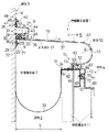
図1は、本発明の実施の一形態の伸縮継手装置1を示す鉛直断面図である。本実施の形態の伸縮継手装置1は、水平方向に空隙2をあけて隣接して設けられる2つの建物3,4間にわたって、前記空隙2を上方から塞ぐように設けられる。この伸縮継手装置1は、可撓性および弾発性を有する材料であるネオプレンゴムから成るシート状のカバー体5、カバー体5の幅方向一端部6を一方の建物3の躯体である外壁構造体7の鉛直な対向壁面8に水密に固定する第1固定手段9、カバー体5の幅方向他端部10を他方の建物4の屋根構造体11の笠木12を覆う笠木カバー13の上面14に水密に固定する第2固定手段15、およびカバー体5の幅方向両端部6,10間の中間部16を下方から弾発的に支持する支持部材17とを含む。
【0008】
前記カバー体5は、平坦状に展開した状態における幅が本実施の形態では約680mmであり、図1の紙面に垂直な長手方向の長さが15mである。このような定尺のカバー体5は、工場において未加硫状態で幅方向両端部を加熱してほぼ直角に曲げ加工した後、長手方向一端部を厚み方向に約30〜45°に斜め切りした後、バフ掛けし、溶剤によって払拭して糊出しし、乾燥した後、接着剤を塗布して対向する長手方向各端部を突き合わせた状態に配置し、この状態でロールによって圧着する。
【0009】
次に、厚みがたとえば1mm幅が100mm、カバー体5と同様な材料、すなわち本実施の形態ではネオプレンゴムから成る未加硫の接続用補強テープを厚み方向両側からカバー体5の幅方向全長にわたって貼付け、同様にロールを用いて圧着する。このようにして長手方向に突き合わせられた接続部分を挟んで厚み方向両側に接続用補強テープが接着された領域を金型によって厚み方向両側から挟持し、140℃に加熱した状態を約30〜40分維持して加硫し、現場に応じた所要長さにわたって連続したカバー体5が形成される。
【0010】
本実施の他の形態では、前記カバー体5の材料として、前記ネオプレンゴムに代えて、クロロプレンゴム(略称CR)またはエチレンプロピレンゴム(略称EPDM)を用いることができる。このようなカバー体5の長手方向の接続作業は、現場において行われ、これによってむやみに長いカバー体5を運搬して現場に搬入する必要がなく、資材搬入作業の手間が低減される。
【0011】
前記第1固定手段9は、一方の建物3の対向壁面8にボルト21およびナット22によって固定される縁材23と、縁材23にビス24によってカバー体5の幅方向一端部6を挟んだ状態で固定される押え金具25と、縁材23および押え金具25を上方から覆い、前記対向壁面8上にタッピンねじ26によって固定される化粧カバー27とを有する。前記縁材23、押え金具25および化粧カバー27は、図1の紙面に垂直な長手方向に延びる長尺材である。
【0012】
前記縁材23は、前記笠木カバー13の上面14よりも上方に配置され、長手方向にたとえば600mm毎に間隔をあけて上下に延びる長孔28が形成される。各長孔28には前記ボルト21が挿通し、この状態で縁材23を上下に位置決めしてナット22を締付け、カバー体5の幅方向一端部6の取付け高さを調整することができる。
【0013】
この縁材23の前記ビス24が螺着される上端部と対向壁面8との間には、縁材23の長手方向全長にわたって上方に開放した凹溝29が形成され、この凹溝29にはバックアップ材30を嵌め込んで、その上方にシール材31が打設され、縁材23と対向壁面8との間を水密に塞いでいる。
【0014】
このような縁材23の前記長孔28が形成される基部32と対向壁面8との間には、補助止水シート33の幅方向一端部が挟持される。この補助止水シート33は、厚さ1.0mmのエチレンプロピレンゴムまたはブチルゴムなどの可撓性および耐候性を有する材料から成り、取付状態においては、図1に示されるように、上方に開放したU字状に下方に垂下して設けられ、幅方向他端部は前記第2固定手段15の縁材34によって笠木カバー13の上面14上に挟持されている。
【0015】
押え金具25は、L字状断面を成し、アルミニウム合金の押出し形材から成る。この押え金具25が前述したようにビス24によって縁材23に固定された状態では、この縁材23と押え金具25との間に介在されるカバー体5の幅方向一端部6を大きな強度で挟持するとともに、この幅方向一端部6にほぼ直角に屈曲して連なる付け根部分35を支持部材17上で押え付け、カバー体5の垂下がりを防止して水密に固定している。
【0016】
支持部材17の基端部は、カバー体5の前記中間部16から付け根部分35を経て縁材23の基部上で下方に屈曲し、縁材23上に座板36によって押え付けられた状態で固定されている。この支持部材17は、長手方向に垂直な断面形状が大略的にL字状であり、その厚みが1.6mm程度の鋼鉄製である。先端部37は屋根構造体11の笠木12の直上近傍まで張り出し、カバー体5の中間部16を下方から弾発的に支持している。このような支持部材27は、図1の紙面に垂直な方向の幅が、本実施の形態では47mmに選ばれ、前記座板36およびナット22によって固定される取付部38と、前記先端部37とを含む。カバー体5の前記取付部38と中間部16を支持する支持部39とは、約86°程度の角度を成して屈曲されている。
【0017】
このような支持部材17によってカバー体5の中間部16が下方から支持されるので、前記中間部16のうち付け根部分35から湾曲開始部分40にわたる平坦状の領域は、対向壁面8から離反するにつれて下方に排水勾配iを成して傾斜している。この排水勾配iは、たとえば5%に選ばれる。
【0018】
前記化粧カバー27は、タッピンねじ26によって対向壁面80に固定される取付部分41と、取付部分41の上端部に連なり、上方になるにつれて対向壁面8から離反する方向に傾斜する上屈曲部分42と、取付部分41の下端部から壁面に対して離反する方向に屈曲して連なり、壁面8から離反するにつれて下方に傾斜する排水勾配を有する水切部分43と、水切部分43の先端部から下方に屈曲して連なる側壁部分44と、側壁部分44の下端部から対向壁面8に近接する方向にほぼ直角に屈曲して連なる下屈曲部分45とを有する。
【0019】
下屈曲部分45と押え金具25との間には、バックアップ材46が嵌め込まれ、下屈曲部分45とカバー体5の付け根部分35との間にはシール材47が打設される。このようなシール材47によって化粧カバー27とカバー体5との間の水密性が達成される。前記上屈曲部分42と対向壁面8との間には、シール材48が打設される。このシール材48によって、化粧カバー27と対向壁面8との間の水密性が達成される。取付部分41から突出するタッピンねじ26の頭部は、シール材49によって覆われ、このシール材49によって取付部分41とタッピンねじ26との間の隙間が塞がれ、水密性が達成される。
【0020】
このようにして第1固定手段9は、カバー体5の幅方向一端部6を一方の建物3の外壁構造体7の対向壁面8に水密に固定する。
【0021】
前記カバー体5の幅方向両端部6,10のうち少なくとも一方の端部である幅方向他端部10に連なる一側部50は、外方に凸に湾曲させた状態で折返され、湾曲部51が形成される。この湾曲部51は、前記湾曲開始部分40から大略的に半円筒状を成す湾曲終了部分52にわたって半径Rで湾曲して形成され、この湾曲終了部分52は付け根部分53を介してほぼ直角に屈曲された幅方向他端部10に連なる。この付け根部分53および幅方向他端部10は、前記第2固定手段15によって他方の建物4の屋根構造体10の上方に立上がる笠木12に固定される。
【0022】
第2固定手段15は、タッピンねじ61によって笠木カバー13および笠木12に固定される前述した縁材34と、この縁材34にビス62によって取付けられる押え金具63とを有する。カバー体5の幅方向一端部10およびその付け根部分53は縁材34および押え金具63によって挟持され、幅方向他端部10の先端部分64は図1の紙面に垂直な長手方向全長にわたって笠木カバー13の上面14に弾発的に当接している。これによってカバー体5の幅方向他端部10と笠木カバー13との間の水密性が向上される。
【0023】
また前記笠木カバー13の上面14と押え金具63との間および前記笠木カバー13の上面14とカバー体5の湾曲終了部分62付近との間には凹溝65が形成され、この凹溝65にはバックアップ材66が嵌め込まれ、シール材67が打設される。このシール材67によってカバー体5と笠木カバー13との間の水密性が達成される。笠木カバー13の下端部とその下方に配置される水切りカバー68の上端部とはビス69によって笠木12に固定され、このビス69の頭部が露出する凹溝70にはバックアップ材71が嵌まり込み、シール材72が打設されて水切りカバー68および笠木カバー13間の水密性が達成されている。前記笠木12、笠木カバー13、縁材34、押え金具63および水切りカバー68は、図1の紙面に垂直な長手方向に延びる長尺材である。このようにして第2固定手段15は、カバー体5の幅方向他端部10を他方の建物4の屋根構造体11の笠木12に水密に固定する。
【0024】
上記のような構成を有する伸縮継手装置1は、図1の紙面に垂直な長手方向に上方に凸に湾曲して各建物3,4間にわたって設けられ、各建物3,4が地震または地盤の不等沈下などによって相互に近接/離反する方向、上下方向、および図1の紙面に垂直な前後方向に相対的な変位を生じても、これらのあらゆる方向の変位を許容して、空隙2を塞ぎ、外部から空隙2内へ風雨が浸入することを確実に防止することができる。各躯体3,4の相互に近接/離反する方向、すなわち図1の左右方向の空隙2を形成する間隔Lは、約30cm程度である。このような大きな間隔Lを、図1の紙面に垂直な長手方向に上方に凸に湾曲して設けられるカバー体5によって塞ぐことができ、上記の各方向への変位に対して高い追従性を達成し、簡単な構成で、幅Lが約30cm程度の広い空隙2を塞いだ状態に維持することができる。
【0025】
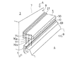
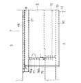
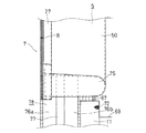
図2は、図1に示される伸縮継手装置1の一端部付近の外観を示す斜視図であり、図3は図2の矢視Aから見た伸縮継手装置1の一端部付近の平面図であり、図4は図2の矢視Bから見た伸縮継手装置1の一端部付近の正面図であり、図5は図2の矢視Cから見た伸縮継手装置1の一端部付近の側面図である。前述したように伸縮継手装置1は、図4に示す正面側から見て一端部から他端部にわたって上方に凸に湾曲して設けられ、その曲率半径R1は、たとえば80〜120m程度である。カバー体5の長手方向両端部には、カバー体5と同一材料から成る小口蓋体75が熱融着または接着剤によってカバー体5の長手方向両端部の小口に固着され、カバー体5の長手方向両端部の開口を塞いでいる。このような小口蓋体75が設けられる長手方向両端部の下方の領域は、上下に延びる一対の延在カバー76a,76b間にカバープレート77が挟持された状態で保持される竪型伸縮継手装置78によって塞がれている。
【0028】
【発明の効果】
本発明によれば、可撓性および弾発的を有するシート状のカバー体の幅方向他端部に連なる一側部を外方に凸に湾曲させた状態で各躯体に設けられ、このカバー体の幅方向両端部間の中間部を弾発的に支持するように構成されるので、前記従来の技術に関連して述べたように、カバー体の厚みをむやみに大きくすることなしに垂れ下がりを防止し、かつ各躯体の相互に近接/離反する方向、上下方向および水平面上で近接/離反する方向に対して垂直な前後方向に相対的な変位を許容し、簡単な構成で各躯体間の空隙を確実に塞いだ状態に維持することができる。
【図面の簡単な説明】
【図1】 本発明の実施の一形態の伸縮継手装置1を示す鉛直断面図である。
【図2】 図1に示される伸縮継手装置1の一端部付近の外観を示す斜視図である。
【図3】 図2の矢視Aから見た伸縮継手装置1の一端部付近の平面図である。
【図4】 図2の矢視Bから見た伸縮継手装置1の一端部付近の正面図である。
【図5】 図2の矢視Cから見た伸縮継手装置1の一端部付近の側面図である。
【符号の説明】
1 伸縮継手装置
2 空隙
3,4 建物
5 カバー体
6 幅方向一端部
7 外壁構造体
8 対向壁面
9 第1固定手段
10 幅方向他端部
11 屋根構造体
12 笠木
13 笠木カバー
15 第2固定手段
16 中間部
17 支持部材
23,34 縁材
25,63 押え金具
33 補助止水シート
51 湾曲部[0001]
BACKGROUND OF THE INVENTION
The present invention relates to an expansion joint device that closes a gap between adjacent buildings and allows rapid and large displacements in the horizontal and vertical directions due to earthquakes and the like.
[0002]
[Prior art]
A typical prior art is disclosed in, for example, Japanese Patent Laid-Open No. 6-322841. In this conventional technique, it is shown that a rubber cover body is used as an airtight material for a building in an expansion joint device in which both ends in the width direction are fixed to two adjacent buildings with a gap between each other. This building airtight material is formed into a corrugated shape that is alternately and unevenly approximately two-dimensionally, and the housings of each building are relatively vertically and vertically and close to and away from each other, and in the above and below directions on a horizontal plane. It is configured such that followability can be obtained in each of the vertical front and rear directions.
[0003]
[Problems to be solved by the invention]
In the above-described conventional technology, as the width of the space between the housings increases, the width and weight of the building airtight material also increase, and there arises a problem that the intermediate portion in the width direction hangs down by its own weight. In order to solve this problem, it is necessary to increase the thickness of the building airtight material to increase the rigidity. However, if the thickness is increased and the rigidity is increased in this way, each housing is relatively displaced. In addition to the problem that the followability is reduced, the both ends of the width direction must be fixed to each housing with great strength, and the mounting structure such as mounting bolts and mounting brackets There arises a problem that the structure becomes large and strong.
[0004]
An object of the present invention is to provide an expansion joint device that can close a wide gap in the width direction with a simple configuration without deteriorating the followability to relative displacement between the respective bodies.
[0005]
[Means for Solving the Problems]
The invention, of the two precursors to adjacent at air gap from each other, the vertical facing walls of one of the skeleton, one widthwise end of the sheet-shaped cover body having flexibility and elasticity is watertight fixed Rutotomoni, out of the two precursors, the top surface of the other skeleton, the other widthwise end portion of the cover body is fixed in a watertight manner,
One side connecting to other widthwise end portion of the cover member is folded in a state of being curved in a convex outward,
In the expansion joint device, an intermediate portion between both end portions in the width direction of the cover body is elastically supported by a support member whose base end portion is fixed to the one casing .
[0006]
According to the present invention, folded in a state where the one side portion continuous in the width direction other end portion fixed to the building frame was curved convexly outward, a sheet, that is, the thickness is substantially uniform flat cover Are fixed to each housing in a watertight manner, and an intermediate portion between both ends in the width direction of the cover body is elastically supported by at least one housing. Since the cover body is a sheet made of a material having flexibility and elasticity, the cover body is in the direction of approaching and separating, and the direction of approaching and separating from each other on the horizontal plane. Therefore, it is deformed flexibly in the vertical front-rear direction as well as the vertical direction so that no great stress is generated. Accordingly, it is not necessary to increase the thickness of the cover body, and when the relative displacement of each casing occurs with a simple configuration, the casings do not hang down by the folded portion bent outwardly. The relative displacement between the both ends in the width direction of the cover body accompanying the relative displacement of the cover body can be allowed. In this way, it is possible to maintain high followability with respect to a relative displacement in an arbitrary direction between the large and large housings, reliably block the gap, and prevent entry of wind and rain into the gap.
[0007]
DETAILED DESCRIPTION OF THE INVENTION
FIG. 1 is a vertical sectional view showing an expansion joint device 1 according to an embodiment of the present invention. The expansion joint device 1 of the present embodiment is provided so as to block the gap 2 from above between two
[0008]
In the present embodiment, the
[0009]
Next, a material having a thickness of, for example, 1 mm and a width of 100 mm and a material similar to that of the
[0010]
In another embodiment of the present invention, chloroprene rubber (abbreviation CR) or ethylene propylene rubber (abbreviation EPDM) can be used as the material of the
[0011]
The first fixing means 9 includes an
[0012]
The
[0013]
Between the upper end portion of the
[0014]
One end in the width direction of the auxiliary
[0015]
The
[0016]
The base end portion of the support member 17 is bent downward on the base portion of the
[0017]
Since the
[0018]
The
[0019]
A
[0020]
Thus, the 1st fixing means 9 fixes the width direction one
[0021]
One
[0022]
The second fixing means 15 includes the above-described
[0023]
A concave groove 65 is formed between the
[0024]
The expansion joint device 1 having the above-described configuration is provided between the
[0025]
2 is a perspective view showing an external appearance of one end portion of the expansion joint device 1 shown in FIG. 1, and FIG. 3 is a plan view of the vicinity of one end portion of the expansion joint device 1 as viewed from an arrow A in FIG. 4 is a front view of the vicinity of one end portion of the expansion joint device 1 as viewed from the arrow B in FIG. 2, and FIG. 5 is a side view near the one end portion of the expansion joint device 1 as viewed from the arrow C in FIG. FIG. As described above, the expansion joint device 1 is provided so as to be convexly curved upward from one end portion to the other end portion when viewed from the front side shown in FIG. 4, and the curvature radius R1 is, for example, about 80 to 120 m. At both ends in the longitudinal direction of the
[0028]
【The invention's effect】
According to the present invention, provided with a flexible and one side that Tsurana the other widthwise end of the sheet-shaped cover body having a resiliently is curved convexly outwards state to each skeleton, Since it is configured to elastically support the intermediate portion between both widthwise ends of the cover body, as described in relation to the conventional technique, the cover body thickness is not increased unnecessarily. And allows relative displacement in the direction of approaching / separating each other, the vertical direction and the direction of approaching / separating on the horizontal plane in the front-rear direction perpendicular to each other. It is possible to maintain a state where the gaps between the casings are reliably closed.
[Brief description of the drawings]
FIG. 1 is a vertical sectional view showing an expansion joint device 1 according to an embodiment of the present invention.
FIG. 2 is a perspective view showing an external appearance in the vicinity of one end of the expansion joint device 1 shown in FIG.
FIG. 3 is a plan view of the vicinity of one end of the expansion joint device 1 as viewed from the direction of arrow A in FIG. 2;
4 is a front view of the vicinity of one end of the expansion joint device 1 as viewed from the direction of arrow B in FIG. 2;
FIG. 5 is a side view of the vicinity of one end of the expansion joint device 1 as viewed from the direction of arrow C in FIG. 2;
[Explanation of symbols]
1 Expansion joint device 2
5 Cover
12 Kasagi
13
17
51 curve
Claims (1)
前記カバー体の幅方向他端部に連なる一側部は、外方に凸に湾曲させた状態で折返され、
前記カバー体の幅方向両端部間の中間部は、基端部が前記一方の躯体に固定された支持部材によって弾発的に支持されることを特徴とする伸縮継手装置。Mutual of the two precursors to adjacent spaced voids, the vertical facing walls of one of the skeleton, one widthwise end of the sheet-shaped cover body having flexibility and elasticity is Ru is fixed watertightly And the other end in the width direction of the cover body is watertightly fixed to the upper surface of the other casing among the two casings ,
One side connecting to other widthwise end portion of the cover member is folded in a state of being curved in a convex outward,
The expansion joint apparatus according to claim 1, wherein the intermediate portion between both end portions in the width direction of the cover body is elastically supported by a support member whose base end portion is fixed to the one casing.
Priority Applications (1)
| Application Number | Priority Date | Filing Date | Title |
|---|---|---|---|
| JP17596999A JP4132425B2 (en) | 1999-06-22 | 1999-06-22 | Expansion joint device |
Applications Claiming Priority (1)
| Application Number | Priority Date | Filing Date | Title |
|---|---|---|---|
| JP17596999A JP4132425B2 (en) | 1999-06-22 | 1999-06-22 | Expansion joint device |
Publications (2)
| Publication Number | Publication Date |
|---|---|
| JP2001003461A JP2001003461A (en) | 2001-01-09 |
| JP4132425B2 true JP4132425B2 (en) | 2008-08-13 |
Family
ID=16005424
Family Applications (1)
| Application Number | Title | Priority Date | Filing Date |
|---|---|---|---|
| JP17596999A Expired - Fee Related JP4132425B2 (en) | 1999-06-22 | 1999-06-22 | Expansion joint device |
Country Status (1)
| Country | Link |
|---|---|
| JP (1) | JP4132425B2 (en) |
Families Citing this family (6)
| Publication number | Priority date | Publication date | Assignee | Title |
|---|---|---|---|---|
| US8707647B2 (en) | 2007-02-23 | 2014-04-29 | Crego Metal Systems, Inc. | Single-ply roofing system |
| US20080202040A1 (en) * | 2007-02-23 | 2008-08-28 | Crego Metal Systems, Inc. | Single ply roofing system |
| KR100762295B1 (en) | 2007-03-09 | 2007-10-01 | 주식회사 에스피케이 얼라이언스 | Leaf spring for panel mounting |
| US20090288358A1 (en) * | 2008-05-22 | 2009-11-26 | Snyder Leland D | Insulative and weather-resistant building construction |
| WO2010019139A1 (en) * | 2008-08-13 | 2010-02-18 | Hansen William J | Insulation system, and methods of constructing and utilizing same |
| US8256165B2 (en) | 2009-06-02 | 2012-09-04 | Crego Metal Systems, Inc. | Single ply roofing system |
-
1999
- 1999-06-22 JP JP17596999A patent/JP4132425B2/en not_active Expired - Fee Related
Also Published As
| Publication number | Publication date |
|---|---|
| JP2001003461A (en) | 2001-01-09 |
Similar Documents
| Publication | Publication Date | Title |
|---|---|---|
| KR100696906B1 (en) | Deformable Building Seat Baton | |
| WO1984001798A1 (en) | Window unit | |
| CN1213882C (en) | Sealing structure | |
| JPH09510271A (en) | Cantilever roof structure | |
| JP4132425B2 (en) | Expansion joint device | |
| US7735891B2 (en) | Corner rail extrusion | |
| JP3649094B2 (en) | Sealing structure of outer wall joint | |
| CN108193813B (en) | Open unitized stone curtain wall | |
| KR102069762B1 (en) | panel frame waterproofing assembly for opened joint panel | |
| US20200224413A1 (en) | Mounting mechanism with horizontal and vertical restraint and method thereof | |
| JPH0860756A (en) | Gasket for outer wall panel and its installation method | |
| JPH09317130A (en) | Water-tight connection structure and packing for floor panel | |
| JP3322825B2 (en) | Outer wall joint waterproof structure | |
| JPH08199920A (en) | Double glazing with attachment | |
| JP4162827B2 (en) | Drainage members and buildings | |
| JP3542518B2 (en) | Panel plate material assembling and mounting structure, and panel plate material assembling and mounting method | |
| JP3666919B2 (en) | Expansion and waterproofing joint | |
| JP4068767B2 (en) | Draining material and waterproof structure on or under the window | |
| JP2898250B2 (en) | Connection structure of metal roofing material | |
| JPH07279393A (en) | Horizontal joint waterproof structure for outer wall | |
| JPH08151695A (en) | Drainer | |
| RU2000102886A (en) | HARNESS WINDOW WITH FASTENING CLAMP FOR VAPOR INSULATION MEMBRANE | |
| JPH09209465A (en) | Sealing device for outer wall joints | |
| JP4083031B2 (en) | Roof tile building construction method | |
| JP4247047B2 (en) | Vertical joint waterproof structure between outer wall panels and outer wall panels |
Legal Events
| Date | Code | Title | Description |
|---|---|---|---|
| A621 | Written request for application examination |
Free format text: JAPANESE INTERMEDIATE CODE: A621 Effective date: 20060622 |
|
| A977 | Report on retrieval |
Free format text: JAPANESE INTERMEDIATE CODE: A971007 Effective date: 20071018 |
|
| A131 | Notification of reasons for refusal |
Free format text: JAPANESE INTERMEDIATE CODE: A131 Effective date: 20071218 |
|
| A521 | Written amendment |
Free format text: JAPANESE INTERMEDIATE CODE: A523 Effective date: 20080218 |
|
| TRDD | Decision of grant or rejection written | ||
| A01 | Written decision to grant a patent or to grant a registration (utility model) |
Free format text: JAPANESE INTERMEDIATE CODE: A01 Effective date: 20080520 |
|
| A01 | Written decision to grant a patent or to grant a registration (utility model) |
Free format text: JAPANESE INTERMEDIATE CODE: A01 |
|
| A61 | First payment of annual fees (during grant procedure) |
Free format text: JAPANESE INTERMEDIATE CODE: A61 Effective date: 20080602 |
|
| FPAY | Renewal fee payment (event date is renewal date of database) |
Free format text: PAYMENT UNTIL: 20110606 Year of fee payment: 3 |
|
| R150 | Certificate of patent or registration of utility model |
Free format text: JAPANESE INTERMEDIATE CODE: R150 |
|
| FPAY | Renewal fee payment (event date is renewal date of database) |
Free format text: PAYMENT UNTIL: 20120606 Year of fee payment: 4 |
|
| LAPS | Cancellation because of no payment of annual fees |