JP4131981B2 - Pattern prediction method and program - Google Patents
Pattern prediction method and program Download PDFInfo
- Publication number
- JP4131981B2 JP4131981B2 JP2007038646A JP2007038646A JP4131981B2 JP 4131981 B2 JP4131981 B2 JP 4131981B2 JP 2007038646 A JP2007038646 A JP 2007038646A JP 2007038646 A JP2007038646 A JP 2007038646A JP 4131981 B2 JP4131981 B2 JP 4131981B2
- Authority
- JP
- Japan
- Prior art keywords
- pattern
- optical system
- projection optical
- photomask
- light
- Prior art date
- Legal status (The legal status is an assumption and is not a legal conclusion. Google has not performed a legal analysis and makes no representation as to the accuracy of the status listed.)
- Expired - Fee Related
Links
Images
Landscapes
- Exposure Of Semiconductors, Excluding Electron Or Ion Beam Exposure (AREA)
- Exposure And Positioning Against Photoresist Photosensitive Materials (AREA)
Description
本発明は、半導体装置のリソグラフィプロセス中で形成されるパターンの予測方法および上記パターンの予測方法をコンピュータに実行させるためのプログラムに関する。 The present invention relates to a method for predicting a pattern formed in a lithography process of a semiconductor device and a program for causing a computer to execute the method for predicting the pattern.
半導体デバイスの製造工程の一つである光リソグラフィ工程では、露光装置が使用される。露光装置は、フォトマスクに露光光、例えばArFエキシマレーザー光を照射し、感光性樹脂(フォトレジスト)が塗布された基板表面にマスクパターンを縮小投影露光する。 An exposure apparatus is used in an optical lithography process that is one of the manufacturing processes of a semiconductor device. The exposure apparatus irradiates a photomask with exposure light, for example, ArF excimer laser light, and performs reduced projection exposure of the mask pattern on the substrate surface coated with a photosensitive resin (photoresist).
フォトマスクに入射した露光光はマスクパターンにおいて回折する。回折光は投影レンズを通過して基板上に集光し、基板表面近傍に光学像と呼ばれる干渉パターンを形成し、この干渉パターンに沿ってフォトレジストが感光する。 The exposure light incident on the photomask is diffracted by the mask pattern. The diffracted light passes through the projection lens and is condensed on the substrate to form an interference pattern called an optical image near the substrate surface, and the photoresist is exposed along the interference pattern.
露光された基板を現像処理することにより、基板表面に微細なパターンが形成される。微細パターン形成技術は年々進歩し、最近では130nm以下の小さい寸法のレジストパターンを形成することが可能となっている。 By developing the exposed substrate, a fine pattern is formed on the substrate surface. The fine pattern formation technology has advanced year by year, and recently, it has become possible to form a resist pattern having a small dimension of 130 nm or less.
微細なレジストパターンを形成するには、露光量(露光光のエネルギー)の制御が重要である。適切な光強度で露光を行うことによって、フォトレジストを適度に感光させ、その結果として基板上に所望寸法のレジストパターンが形成される。 In order to form a fine resist pattern, it is important to control the exposure amount (exposure light energy). By performing exposure with an appropriate light intensity, the photoresist is appropriately exposed, and as a result, a resist pattern having a desired dimension is formed on the substrate.
露光量が高すぎても低すぎても所望寸法にはならない。レジストパターンが所望寸法でない場合、その後の工程を経て製造される半導体デバイスは正常に動作せず、不良品となる。 If the exposure amount is too high or too low, the desired dimensions are not achieved. When the resist pattern is not a desired dimension, a semiconductor device manufactured through the subsequent process does not operate normally and becomes a defective product.
そのため、製造工程においては、露光後に、レジストパターンの寸法を例えば電子顕微鏡などを用いて測定する。寸法が所望値でない場合には、フォトレジストを剥離し、光リソグラフィ工程の最初からやり直す。 Therefore, in the manufacturing process, after exposure, the dimension of the resist pattern is measured using, for example, an electron microscope. If the dimension is not the desired value, the photoresist is stripped and the photolithography process is started again.
露光装置が一括して露光する領域の大きさは一辺が数十ミリの矩形であり、この領域(一括露光領域)内に1個以上の半導体デバイスが形成される。したがって、露光においては、一括露光領域内の全ての位置で、レジストパターンを所望の寸法に仕上げなければならない。 The size of the region exposed by the exposure apparatus is a rectangle with a side of several tens of millimeters, and one or more semiconductor devices are formed in this region (collective exposure region). Therefore, in exposure, the resist pattern must be finished to a desired dimension at all positions within the batch exposure region.
一般に、1回の露光で転写されるパターンには、密集したパターン、孤立したパターンなど様々なものが含まれている。露光波長と同程度か、あるいはそれよりも小さい寸法のパターンを形成する場合、マスクパターンを形成すべきレジストパターンと相似な形状に、すなわちレジストパターンを投影レンズの縮小率で除算して算出される寸法に設計しても、全てのパターンが所望寸法に仕上がるわけではない。 Generally, various patterns such as a dense pattern and an isolated pattern are included in a pattern transferred by one exposure. When forming a pattern with dimensions similar to or smaller than the exposure wavelength, the mask pattern is calculated to be similar to the resist pattern to be formed, that is, the resist pattern is divided by the reduction ratio of the projection lens. Even if the dimensions are designed, not all patterns are finished to the desired dimensions.
そこで、例えば、密集パターンと孤立パターンとが同じレジスト寸法に仕上がるように、双方のマスク寸法を、レジストパターンを投影レンズの縮小率で除算して算出される寸法とは異なる値に、マスク設計寸法を変える。このマスク寸法の変更量をマスクバイアスと呼んでおり、パターンの種類によって異なるマスクバイアスを与えて、レジスト仕上がり寸法を調節する。 Therefore, for example, the mask design dimension is set to a value different from the dimension calculated by dividing the resist pattern by the reduction ratio of the projection lens so that the dense pattern and the isolated pattern are finished to the same resist dimension. change. This amount of change in the mask dimension is called a mask bias, and the resist finish dimension is adjusted by applying a different mask bias depending on the type of pattern.
ところで、実際の露光装置においては、光が通る経路に依存して光の振幅が異なる量だけ減衰する現象(以下、瞳透過率変動という。)が発生している。その原因は、例えば、特許文献1で述べられているような、投影光学系を構成するレンズの反射防止膜の不均一性、あるいはレンズの厚さによる透過率低下などがある。
By the way, in an actual exposure apparatus, a phenomenon (hereinafter referred to as pupil transmittance fluctuation) in which the amplitude of light attenuates by a different amount depending on the path through which light passes is occurring. The cause is, for example, the non-uniformity of the antireflection film of the lens constituting the projection optical system as described in
投影光学系内における回折光の経路が異なれば、一般には、投影レンズに入射する回折光の角度や、投影レンズ内部を通過する回折光の距離が変わる。そのため、回折光の経路によっては投影光学系の透過率が変わる。特に、現在レンズ材として一般的に使用されている溶融石英は、波長が200nmより短い光に対しては、短波長であるほど透明性が低下する傾向がある。したがって、瞳透過率変動はArF露光装置(露光波長193nm)において特に大きな値を示す。 If the path of the diffracted light in the projection optical system is different, generally, the angle of the diffracted light incident on the projection lens and the distance of the diffracted light passing through the projection lens change. For this reason, the transmittance of the projection optical system varies depending on the path of the diffracted light. In particular, fused silica that is generally used as a lens material at present tends to have lower transparency with respect to light having a wavelength shorter than 200 nm as the wavelength is shorter. Therefore, the pupil transmittance variation is particularly large in the ArF exposure apparatus (exposure wavelength 193 nm).
回折光が通る経路はマスクパターンによって異なるから、投影レンズに瞳透過率変動がある場合、投影光学系の透過率はマスクパターンによって異なる影響を受ける。結果的に、レジストパターンを所望寸法に仕上げるための最適露光量が変化する。しかも、この変化の大きさは、パターンの種類によって、例えば密集パターンと孤立パターンの間で異なる。 Since the path through which the diffracted light passes varies depending on the mask pattern, if the projection lens has a pupil transmittance variation, the transmittance of the projection optical system is affected differently by the mask pattern. As a result, the optimum exposure amount for finishing the resist pattern to a desired dimension changes. In addition, the magnitude of this change varies, for example, between a dense pattern and an isolated pattern depending on the type of pattern.
したがって、密集パターンと孤立パターンとを同時に所望寸法に仕上げるように各パターンのマスクバイアスを設計したとしても、瞳透過率変動を考えていなければ、二つのパターンが同時には所望寸法にならない恐れがある。 Therefore, even if the mask bias of each pattern is designed so that the dense pattern and the isolated pattern are finished to a desired size at the same time, the two patterns may not have the desired size at the same time unless the pupil transmittance variation is taken into consideration. .
このよう不都合を未然に防止するために、マスクバイアスを変えたフォトマスクを予め複数準備して、試行錯誤的に最適なマスクバイアスを求める方法が考えられるが、必要な時間およびコストが膨大となり、実用的な方法とはいえなかった。 In order to prevent such inconvenience in advance, a method of preparing a plurality of photomasks with different mask biases in advance and obtaining an optimal mask bias by trial and error can be considered, but the time and cost required are enormous, It was not a practical method.
また、瞳透過率変動の影響を防止するために、投影光学系が持つ瞳変動率の大きさを計測し、この計測結果に基づいて感光基板上の光学像を予測し、この予測した光学像と設計上の光学像とが一致するように、フォトマスクを設計する方法が考えられる。 In order to prevent the influence of pupil transmittance fluctuation, the pupil fluctuation rate of the projection optical system is measured, and the optical image on the photosensitive substrate is predicted based on the measurement result. It is conceivable to design a photomask so that the design optical image matches the design optical image.
瞳透過変動率の大きさの計測方法は、例えば、特許文献2に開示されている。この計測方法を実施することにより、瞳座標系の複数の点における透過率の分布が判明する。
A method for measuring the magnitude of the pupil transmission variation rate is disclosed in
しかし、上記従来の計測方法は、瞳透過率変動を、瞳面におけるマトリクスデータとして取り込んで計算を行っているので、瞳面内で複雑に変化する瞳透過率変動を取り込もうとすると、必要なデータ量が膨大となる。そのため、従来の計測方法の計測結果に基づいて行われる光学像の予測方法、さらにこの光学像の予測方法を用いたフォトマスクの設計方法は、実用的な方法とはいえなかった。
上述の如く、露光装置の投影光学系に瞳透過率変動がある場合、レジストパターン寸法を高精度に所望寸法に仕上げるために、マスクバイアスを変えたフォトマスクを予め複数準備して、試行錯誤的に最適なマスクバイアスを求める方法が提案されているが、必要な時間およびコストが膨大となり、実用的な方法とはいえなかった。 As described above, when there is a variation in pupil transmittance in the projection optical system of the exposure apparatus, in order to finish the resist pattern dimension to a desired dimension with high accuracy, a plurality of photomasks with different mask biases are prepared in advance. Although a method for obtaining an optimal mask bias has been proposed, the time and cost required are enormous, and it cannot be said to be a practical method.
また、瞳透過変動率の大きさを従来の計測方法で求め、この計測結果に基づいて感光基板上の光学像を予測し、この予測した光学像と設計上の光学像とが一致するように、フォトマスクを設計する方法が考えられる。しかし、従来の計測方法は必要なデータ量が膨大となるため、その計測結果に基づいて行われる光学像の予測方法、さらにこの光学像の予測方法を用いたフォトマスクの設計方法は、実用的な方法とはいえなかった。 In addition, the magnitude of pupil transmission fluctuation rate is obtained by a conventional measurement method, and an optical image on the photosensitive substrate is predicted based on the measurement result so that the predicted optical image matches the designed optical image. A method of designing a photomask can be considered. However, since the conventional measurement method requires a large amount of data, an optical image prediction method based on the measurement result and a photomask design method using this optical image prediction method are practical. It was not a safe method.
本発明は、上記事情を考慮してなされたもので、その目的とするところは、実用的な、リソグラフィプロセス中で形成されるパターンのパターン予測方法および該パターン予測方法をコンピュータに実行させるためのプログラムを提供することにある。 The present invention has been made in consideration of the above circumstances, and an object of the present invention is to provide a practical pattern prediction method for a pattern formed in a lithography process and to cause a computer to execute the pattern prediction method. To provide a program.
本発明に係るパターン予測方法は、フォトマスクに二次光源から発した光を照射し、前記フォトマスクを通過した光を投影光学系を介して感光基板上に集光して形成される前記感光基板上のパターンを予測するパターン予測方法であって、前記投影光学系を通過する光の前記投影光学系内の経路の違いに依存して変化する、前記投影光学系の透過率変動を、前記投影光学系の瞳座標で定義される直交多項式を用いて近似する第一工程と、前記二次光源中の複数の点光源を決める第二工程と、前記複数の点光源のうちの一つから発する光が前記フォトマスクに照射されて、前記マスクパターン通過後に発生する回折光の前記投影光学系内の経路を計算する第三工程と、前記経路を通過する各々の回折光に関して、前記投影光学系の透過率変動を近似する前記直交多項式の展開係数に基づいて光強度の減衰を与える第四工程と、前記各々の回折光が感光基板上に形成する像強度分布を計算する第五工程と、前記複数の点光源の残りのすべての点光源に対して、前記第三工程から第五工程までを実施し、前記複数の点光源の各々から得られた像強度分布を足し合わせて一つの像強度分布を求める第六工程と、前記第六工程で求めた像強度分布に基づいて、前記パターンを予測する第七工程とを有することを特徴とする。 In the pattern prediction method according to the present invention, the photomask is formed by irradiating a photomask with light emitted from a secondary light source and condensing the light that has passed through the photomask on a photosensitive substrate via a projection optical system. A pattern prediction method for predicting a pattern on a substrate, the transmittance variation of the projection optical system changing depending on a difference in a path in the projection optical system of light passing through the projection optical system, From the first step of approximation using an orthogonal polynomial defined by the pupil coordinates of the projection optical system, the second step of determining a plurality of point light sources in the secondary light source, and one of the plurality of point light sources A third step of calculating a path in the projection optical system of the diffracted light generated after passing through the mask pattern by irradiating the emitted light to the photomask; and for each diffracted light passing through the path, the projection optics System transmission fluctuation A fourth step for attenuating light intensity based on a similar expansion coefficient of the orthogonal polynomial; a fifth step for calculating an image intensity distribution formed on the photosensitive substrate by each diffracted light; and the plurality of point light sources. Steps 3 to 5 are performed on all remaining point light sources, and the image intensity distribution obtained from each of the plurality of point light sources is added to obtain one image intensity distribution. And a seventh step of predicting the pattern based on the image intensity distribution obtained in the sixth step .
本発明では、投影光学系の透過率変動を近似する直交多項式の展開係数に基づいて、パターンを予測する。ここで、適切な直交多項式を選ぶことにより、透過率変動を少ない展開係数で近似することができ、実用上の障害の原因となるデータ量の増大を防止できるようになる。さらに、上記直交多項式の展開係数は、感光基板上に形成されるパターンに関して物理的な意味を持つようになる。このようなパターンに関しての物理的な知見は、マスクパターン設計において有効である。 In the present invention, the pattern is predicted based on the expansion coefficient of an orthogonal polynomial that approximates the transmittance variation of the projection optical system. Here, by selecting an appropriate orthogonal polynomial, the transmittance variation can be approximated with a small expansion coefficient, and an increase in the amount of data that causes a practical failure can be prevented. Further, the expansion coefficient of the orthogonal polynomial has a physical meaning with respect to the pattern formed on the photosensitive substrate. Such physical knowledge about the pattern is effective in mask pattern design.
本発明では、感光基板上のパターンを予測する際に、上記本発明に係るパターン予測方法を用いているので、実用上の障害の原因となるデータ量の増大を防止できるようになる。 In the present invention, when the pattern on the photosensitive substrate is predicted, the pattern prediction method according to the present invention is used. Therefore, an increase in the amount of data that causes a practical failure can be prevented.
本発明に係るプログラムは、コンピュータに、フォトマスクに二次光源から発した光を照射し、前記フォトマスクを通過した光を投影光学系を介して感光基板上に集光して形成される前記感光基板上のパターンを予測させる手順を実行させるためのプログラムであって、前記投影光学系を通過する光の前記投影光学系内の経路の違いに依存して変化する、前記投影光学系の透過率変動を、前記投影光学系の瞳座標で定義される直交多項式を用いて近似させる第一手順と、前記二次光源中の複数の点光源を決めさせる第二手順と、前記複数の点光源のうちの一つから発する光が前記フォトマスクに照射されて、前記マスクパターン通過後に発生する回折光の前記投影光学系内の経路を計算させる第三手順と、前記経路を通過する各々の回折光に関して、前記投影光学系の透過率変動を近似する前記直交多項式の展開係数に基づいて光強度の減衰を与えさせる第四手順と、前記各々の回折光が感光基板上に形成する像強度分布を計算させる第五手順と、前記複数の点光源の残りのすべての点光源に対して、前記第三手順から第五手順までを実施させ、前記複数の点光源の各々から得られた像強度分布を足し合わせて一つの像強度分布を求めさせる第六手順と、前記第六手順で求めさせた像強度分布に基づいて、前記パターンを予測させる第七手順とを実行させるためのプログラムである。 The program according to the present invention is formed by irradiating a computer with light emitted from a secondary light source on a photomask, and condensing the light that has passed through the photomask onto a photosensitive substrate via a projection optical system. A program for executing a procedure for predicting a pattern on a photosensitive substrate, the transmission of the projection optical system changing depending on a path of the light passing through the projection optical system in the projection optical system A first procedure for approximating rate variation using an orthogonal polynomial defined by pupil coordinates of the projection optical system; a second procedure for determining a plurality of point light sources in the secondary light source; and the plurality of point light sources. A third step of irradiating the photomask with light emitted from one of the above, and calculating a path in the projection optical system of the diffracted light generated after passing through the mask pattern, and each diffraction passing through the path Light A fourth step of giving attenuation of light intensity based on the expansion coefficient of the orthogonal polynomial approximating the transmittance fluctuation of the projection optical system, and an image intensity distribution formed on the photosensitive substrate by each of the diffracted lights And the image intensity obtained from each of the plurality of point light sources by performing the third procedure to the fifth procedure for all the remaining point light sources of the plurality of point light sources. A program for executing a sixth procedure for obtaining one image intensity distribution by adding the distributions and a seventh procedure for predicting the pattern based on the image intensity distribution obtained by the sixth procedure. .
本発明の上記ならびにその他の目的と新規な特徴は、本明細書の記載および添付図面によって明らかになるであろう。 The above and other objects and novel features of the present invention will become apparent from the description of the present specification and the accompanying drawings.
本発明によれば、実用的な、リソグラフィプロセス中で形成されるパターンのパターン予測方法および該パターン予測方法をコンピュータに実行させるためのプログラムを実現できるようになる。 According to the present invention, a practical pattern prediction method for a pattern formed in a lithography process and a program for causing a computer to execute the pattern prediction method can be realized.
以下、図面を参照しながら本発明の実施形態を説明する。 Hereinafter, embodiments of the present invention will be described with reference to the drawings.
(第1の実施形態)
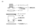
図1は、縮小投影露光装置の一例を示す概略構成図である。図において、1は照明光学系、2〜4はそれぞれ照明光学系1を構成するフライアレイレンズ、照明アパーチャ(二次光源面)およびコンデンサレンズを示している。
(First embodiment)
FIG. 1 is a schematic block diagram showing an example of a reduced projection exposure apparatus. In the figure,
照明光学系1から発した照明光は、一般には、波長が157nm〜365nmの範囲内にある光であり、フォトマスク5上の一辺が10cm程度の矩形のパターン領域をほぼ均一な照度で照明する。
The illumination light emitted from the illumination
フォトマスク5のパターン領域内には、例えば、一方向に周期性を有するパターン(一次元パターン)、周囲のパターンと孤立した孤立パターン、縦横もしくは斜めなど二つの方向に周期性を有するパターン(二次元パターン)などのパターンが配置されている。これらのパターンは、透過領域と遮光領域により構成される。遮光領域の代わりに半透明領域を用いる場合もある(ハーフトーンマスク)。
In the pattern area of the
フォトマスク5に入射した光は上記パターン(パターン面)により回折し、その後、投影光学系6に入射する。投影光学系6は入射した光を集光し、感光基板上(ウェハ)7上にフォトマスク5の像を結ぶ。
The light incident on the
投影光学系6の縮小率をMとすると、フォトマスク5において照明されるパターン領域のサイズが、例えば一辺X[mm]の正方形である場合、感光基板7上における一括露光領域のサイズは一辺M・X[mm]の正方形となる。縮小率Mの値は1/4または1/5の露光装置が一般的である。
When the reduction ratio of the projection
投影光学系6の内部には、投影光学系6の有効な大きさ(直径)を規定する絞り(開口絞り)が存在し、開口絞りが存在する面を瞳または瞳面と呼ぶ。
Inside the projection
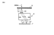
図2は、フォトマスク5上に照明光が入射し、フォトマスク5上で発生した三つの回折光がそれぞれ瞳面内の異なる点を通過し、感光基板7上の一つの像点に到達する様子を模式的に示す図である。図2において、L1〜L3はフォトマスク5を透過し、かつ投影光学系6に入射する前の回折光、L1’〜L3’はフォトマスク5を透過し、かつ投影光学系6を通過した後の回折光を示している。
In FIG. 2, illumination light is incident on the
ここで、投影光学系6に瞳透過率変動がある場合、回折光は経路ごとに異なる量だけ減衰する。この結果、パターン転写に関する露光量の特性は、瞳透過率変動がない場合とは異なるものとなる。
Here, when there is a pupil transmittance variation in the projection
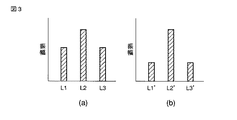
図3に、投影光学系6の中心部と周辺部で透過率が異なる瞳透過率変動がある場合の、投影光学系6に入射する前の回折光L1〜L3の振幅(同図(a))および投影光学系6を透過した後の回折光L1’〜L3’の振幅を示す(同図(b))。
FIG. 3 shows the amplitudes of the diffracted lights L1 to L3 before entering the projection
投影光学系6の中心部と周辺部で透過率が異なるために、投影光学系6の通過後には、回折光L1’,L3’の振幅は減衰する。その結果、回折光L2’に対する回折光L1’,L3’の振幅比(光強度比)は、回折光L2に対する回折光L1,L3の振幅比とは異なるものとなる。
Since the transmittance is different between the central portion and the peripheral portion of the projection
例として、照明アパーチャ3が小さい照明条件(0.3程度)で、フォトマスク5における透過領域と遮光領域の幅の比が1:1、すなわちデューティ(Duty)比が0.5のラインアンドスペースパターン(以下、第1のL&Sパターンという。)と、第1のL&Sパターンより短い周期をもつ、デューティ比が0.5のラインアンドスペースパターン(以下、第2のL&Sパターンという。)とを、感光基板7上の二つの近傍領域にそれぞれ同時に縮小投影する場合を考える。
As an example, a line-and-space in which the ratio of the width of the transmissive area to the light-shielding area in the
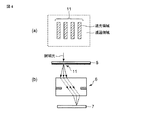
図4は、第1のL&Sパターンおよびその結像に関する回折光の経路を模式的に示す図である。図4に示すように、第1のL&Sパターン11は、遮光領域と透過領域とで構成されている。
FIG. 4 is a diagram schematically showing a path of diffracted light relating to the first L & S pattern and its image formation. As shown in FIG. 4, the first L &
第1のL&Sパターン11により発生する回折光のうち、結像に寄与するのは主として0次回折光および1次回折光である。0次回折光と1次回折光の振幅比はデューティ比に依存する。0次回折光の振幅C0と1次回折光の振幅C1の比率とは、デューティ比βを用いて次のように表される。
Of the diffracted light generated by the first L &
C0:C1=1:sin(πβ)/(πβ)
例えば、デューティ比が0.5の場合、C0:C1=1:0.64となる。
C0: C1 = 1: sin (πβ) / (πβ)
For example, when the duty ratio is 0.5, C0: C1 = 1: 0.64.
次に、投影光学系6の瞳透過率変動を計測する。この瞳透過率変動の計測は、周知の計測方法は、例えば、本出願の筆頭発明者による発明、特開2001−230179の第1の実施形態(段落番号0034〜0049、図1〜4)に記載された方法を用いる。この方法では、フォトマスク5上で発生して投影光学系6を通過する回折光について、投影光学系6の透過率を求めることになる。また、投影光学系6を通過する光の投影光学系6内の多数の経路について、予め投影光学系の透過率を求めておけば、使用するフォトマスク毎に、投影光学系6の透過率を求めることは不要になる。
Next, the pupil transmittance variation of the projection
以下、瞳透過率変動を計測した結果、図5に示すような、投影光学系6の瞳の中央において最も透明で、端に向かって振幅透過率が低下していくような瞳透過率変動が発生していたとして説明を進める。
Hereinafter, as a result of measuring the pupil transmittance fluctuation, as shown in FIG. 5, there is a pupil transmittance fluctuation that is most transparent at the center of the pupil of the projection
投影光学系6に0次回折光および1次回折光が入射する前、それらの振幅比はC0:C1=1:0.64である。第1のL&Sパターン11が作る0次回折光の経路の透過率は1(X=0)である。
Before the 0th-order diffracted light and the 1st-order diffracted light enter the projection
ここで、第1のL&Sパターン11が作る1次回折光の経路の振幅透過率が0.9(X=b)であるとすると、投影光学系6を通過して感光基板7上に到達する直前にはその振幅比はC0:C1=1:0.58に変化する。
Here, assuming that the amplitude transmittance of the path of the first-order diffracted light produced by the first L &
この結果、瞳透過率変動がない場合に比べて像の状態が変化し、パターンが所望寸法に仕上がる最適露光量は変動する。 As a result, the state of the image changes compared to the case where there is no pupil transmittance variation, and the optimum exposure amount at which the pattern is finished to the desired dimension varies.
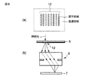
図6に、第2のL&Sパターンおよびその結像に関する光の経路を模式的に示す。第2のL&Sパターン12の1次回折光の経路は、第1のL&Sパターン11の1次回折光の経路とは異なる。
FIG. 6 schematically shows a light path relating to the second L & S pattern and its imaging. The path of the first-order diffracted light of the second L &
投影光学系6に0次回折光と1次回折光が入射する前、それらの振幅比はC0:C1=1:0.64である。第2のL&Sパターン12が作る0次回折光の経路の透過率は1(X=0)である。
Before the 0th-order diffracted light and the 1st-order diffracted light enter the projection
ここで、第2のL&Sパターン12が作る1次回折光の経路の振幅透過率が0.8(X=a)であるとすると、投影光学系6を通過して感光基板7上に到達する直前には回折光の振幅比がC0:C1=1:0.51に変化する。
Here, assuming that the amplitude transmittance of the path of the first-order diffracted light created by the second L &
この結果、瞳透過率変動がない場合に比べて像の状態が変化する。具体的には、第2のL&Sパターン12の最適露光量が変動し、しかも、その変動量は第1のL&Sパターン11の変動量のそれと異なる。
As a result, the state of the image changes compared to the case where there is no pupil transmittance variation. Specifically, the optimal exposure amount of the second L &
すなわち、上記状態では、第1のL&Sパターン11が所望寸法のときに第2のL&Sパターン12が細くなり、逆に、第2のL&Sパターン12が所望寸法のときには、第1のL&Sパターン11が太くなる。したがって、第1および第2のL&Sパターン11,12は同時に所望寸法に仕上がらない。
That is, in the above state, when the first L &
上記問題を解決するために、本実施形態では、マスクバイアス、ここでは第1および第2のL&Sパターン11,12のデューティ比を調節する。例えば、投影光学系6を通過した後の0次回折光と1次回折光の振幅比がC0:C1=1:0.64となるように、第1および第2のL&Sパターン11,12のデューティ比を調節する。
In order to solve the above problem, in this embodiment, the mask bias, here, the duty ratios of the first and second L &
すなわち、入射側の0次回折光と1次回折光の振幅比が、第1のL&Sパターン11ではC0:C1=1:0.71、第2のL&Sパターン12ではC0:C1=1:0.8になるようにすればよい。これは、第1のL&Sパターン11のデューティ比を0.44、第2のL&Sパターン12のデューティ比を0.36に設定するこにより実現できる。
That is, the amplitude ratio between the 0th-order diffracted light and the first-order diffracted light on the incident side is C0: C1 = 1: 0.71 in the first L &
このようにデューティ比を設定すれば、第1および第2のL&Sパターン11,12は、投影光学系6を通過した光の0次回折光と1次回折光の振幅比がC0:C1=1:0.64となる。そのため、感光基板7上に、第1のL&Sパターン11に対応したレジストパターン(以下、第1のL&Sレジストパターンという。)および第2のL&Sパターン12に対応したレジストパターン(以下、第2のL&Sレジストパターンという。)を同時に所望寸法に仕上げることが可能となる。
If the duty ratio is set in this way, the first and second L &
第1および第2のL&Sレジストパターンを同時に所望寸法に仕上げる別の方法として、第1のL&Sパターン11のデューティ比を0.5に維持したまま、第2のL&Sパターン12のデューティ比を変更する方法がある。
As another method for simultaneously finishing the first and second L & S resist patterns to a desired dimension, the duty ratio of the second L &
第1のL&Sパターン11の結像に関する投影光学系6を通過した0次回折光と1次回折光の振幅比はC0:C1=1:0.58であり、第2のL&Sパターン12の結像に関する回折光に関してもこの比率となるようにする。これは、第2のL&Sパターン12のデューティ比を0.54にすることにより実現できる。
The amplitude ratio of the 0th-order diffracted light and the 1st-order diffracted light that has passed through the projection
このようにデューティ比を設定すれば、第1および第2のL&Sパターン11,12は、投影光学系6を通過した光の0次回折光と1次回折光の振幅比がC0:C1=1:0.58となるため、第1および第2のL&Sパターン11,12を同時に所望寸法に仕上げることが可能となる。
If the duty ratio is set in this way, the first and second L &
以上述べたように、本実施形態では、投影光学系6の透過率特性を求め、この透過率特性を用いてマスクバイアスを求めるので、投影光学系6の瞳透過率変動の影響を小さくできるとともに、コスト等を増大させ、実用上の障害の原因となる複数のマスクバイアスを変えたフォトマスクを予め準備する必要がなくなる。 なお、本実施形態では、第1のL&Sパターン11のデューティ比を固定して、第2のL&Sパターン12のデューティ比を変更したが、逆に、第2のL&Sパターン12のデューティ比を固定して、第1のL&Sパターン11のデューティ比を変更しても構わない。この場合、第1のL&Sパターン11のデューティ比は、投影光学系6を通過した光の0次回折光と1次回折光の振幅比がC0:C1=1:0.51となるように設定される。
As described above, in this embodiment, the transmittance characteristic of the projection
また、本実施形態では、2種類のパターンを同時に所望寸法に仕上げる状況を考慮したが、3種類以上の異なる種類のパターンを同時に所望寸法に仕上げる場合であっても、同様の方法ですべてのパターンを同時に所望寸法に仕上げることができる。 Further, in the present embodiment, the situation in which two types of patterns are simultaneously finished to a desired dimension has been considered. However, even when three or more different types of patterns are simultaneously finished to a desired dimension, all patterns are similarly processed. Can be finished to the desired dimensions at the same time.
さらに、本実施形態の方法は、L&Sパターンに限定されず、孤立ラインまたは孤立スペース、ホールパターン、あるいは2次元的な周期性を有するパターンなどいかなるパターンにも適用できる。 Furthermore, the method of the present embodiment is not limited to the L & S pattern, and can be applied to any pattern such as an isolated line or space, a hole pattern, or a pattern having a two-dimensional periodicity.
さらにまた、本実施形態の方法は、σ値=0.3程度の小さい照明条件に限定されず、いかなる照明条件にも適用できる。 Furthermore, the method of the present embodiment is not limited to a small illumination condition with a σ value = about 0.3, and can be applied to any illumination condition.
ただし、複雑な形状のパターンや、大きなσ値の照明の場合は、最適マスクバイアスの算出には複雑な計算が必要となるため、コンピュータを用いて最適解を求める。この場合、回折光の振幅比を計算する変わりに、レジストパターン仕上がり寸法を計算機シミュレーションにより求め、最適なマスクバイアスの条件を求めてもよい。 However, in the case of a pattern with a complicated shape or illumination with a large σ value, the calculation of the optimal mask bias requires a complicated calculation, so the optimal solution is obtained using a computer. In this case, instead of calculating the amplitude ratio of the diffracted light, the resist pattern finished size may be obtained by computer simulation to obtain the optimum mask bias condition.
さらにまた、瞳透過率変動の振る舞いが本実施形態(図5)とは異なる場合であっても、例えば、計算機シミュレーションを行って最適マスクバイアス条件を求め、マスクバイアス設計に反映させることにより、寸法が適切なレジストパターンを形成することが可能となる。 Furthermore, even when the behavior of the pupil transmittance variation is different from that of the present embodiment (FIG. 5), for example, by performing a computer simulation to obtain the optimum mask bias condition and reflecting it in the mask bias design, the dimension However, an appropriate resist pattern can be formed.
(第2の実施形態)
次に、第2の実施形態について説明する。なお、以下の実施形態では、第1の実施形態の図1の露光装置を用いたとして説明する。また、前述した図と同一符号は同一符号または相当部分を示し、詳細な説明は省略する。
(Second Embodiment)
Next, a second embodiment will be described. In the following embodiment, description will be made assuming that the exposure apparatus of FIG. 1 of the first embodiment is used. Further, the same reference numerals as those in the above-described drawings indicate the same reference numerals or corresponding parts, and detailed description thereof is omitted.
前述の通り、半導体デバイスの正常動作のためには、感光基板(ウェハ)7上の一辺20〜35mmの一括露光領域内(フォトマスク5上に換算して一辺80〜140mmの領域内)で、レジストパターンの寸法ばらつきが十分小さい必要がある。 As described above, for the normal operation of the semiconductor device, in the collective exposure region of 20 to 35 mm on one side on the photosensitive substrate (wafer) 7 (in the region of 80 to 140 mm on one side in terms of the photomask 5), The dimensional variation of the resist pattern needs to be sufficiently small.
ここで、瞳透過率変動は一括露光領域内で変動するから、瞳透過率変動は一括露光領域内のパターン寸法変動の原因となる。瞳透過率変動が一括露光領域内で変動する理由は次のように考えることができる。 Here, since the pupil transmittance variation varies within the batch exposure region, the pupil transmittance variation causes the pattern dimension variation within the batch exposure region. The reason why the pupil transmittance fluctuation fluctuates within the batch exposure region can be considered as follows.
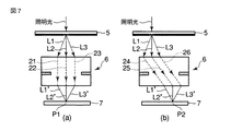
図7は、一括露光領域内の中央付近P1に到達する第1の回折光の投影光学系6内における経路21〜23と、一括露光領域内の端付近P2に到達する第2の回折光の投影光学系6内における経路24〜26とが異なる様子を示している。
FIG. 7 shows the
第1の回折光と第2の回折光とでは、投影光学系6を構成するレンズに対する入射角やレンズ材の内部を通過する距離が異なる。その結果、一括露光領域内の中央付近P1と一括露光領域内の端付近P2とでは異なる瞳透過率変動が計測される。
The first diffracted light and the second diffracted light differ in the incident angle with respect to the lens constituting the projection
瞳透過率変動が一括露光領域内で変動することに起因するパターン寸法ばらつきを抑制する方法を説明する。ここでは、フォトマスク5の一括露光領域内における微細な領域P11〜P13におけるマスクパターンM11〜〜M13は、同一寸法・同一形状のL&Sパターンであるが(図8(a))、瞳透過率変動が原因で、領域P11〜P13に対応した感光基板上の領域P11’〜P13’間でレジストパターンの寸法がばらついていたとする(図8(b))。
A method for suppressing pattern dimension variations caused by fluctuations in pupil transmittance fluctuation in the batch exposure region will be described. Here, the mask patterns M11 to M13 in the fine regions P11 to P13 in the collective exposure region of the
まず、一括露光領域内の領域P11〜P13に到達する光の投影光学系6内における透過率を計測し、投影光学系6の瞳透過率変動を求める。計測方法は、第1の実施形態でも述べたが、例えば本出願の筆頭発明者による発明、特開2001−230179号公報に記載された方法を用いる。
First, the transmittance in the projection
次に、計算機シミュレーションにより、瞳透過率変動を考慮して、マスクバイアスの最適値を一括露光領域内の領域P11〜P13ごとに計算する。 Next, an optimal value of the mask bias is calculated for each of the areas P11 to P13 in the collective exposure area in consideration of the pupil transmittance variation by computer simulation.
ここで、一括露光領域内の領域ごとのマスクバイアス最適値とは、一括露光領域内の複数の異なる領域内に存在する同一形状のパターンが同時に所望寸法に仕上がるようなマスクバイアスの大きさのことで、同一形状のレジストパターンを形成するマスクパターンのマスクバイアスを一括露光領域の領域ごとに変えることを意味している。 Here, the mask bias optimum value for each region in the batch exposure region is the mask bias size that allows the same shape pattern existing in a plurality of different regions in the batch exposure region to be finished to a desired dimension at the same time. This means that the mask bias of the mask pattern for forming the resist pattern having the same shape is changed for each of the batch exposure regions.
領域ごとのマスクバイアス最適値の決め方はいくつか考えられる。例えば、ある基準状態を定め、全てのパターンが基準状態と同一になるように、全てのパターンのマスクバイアスを変えてもよいし、あるいは一括露光領域内のある一つの領域を基準状態として、他の領域における像の状態を基準状態に一致するように、マスクバイアスを決定しても構わない。 There are several ways of determining the optimum mask bias value for each region. For example, a certain reference state may be defined, and the mask bias of all patterns may be changed so that all patterns are the same as the reference state, or one region in the batch exposure region may be used as a reference state and the other The mask bias may be determined so that the state of the image in the region matches the reference state.
最後に、求めたマスクバイアスを用いてフォトマスク5を設計し、製造する。このようにして設計されたフォトマスク5の転写によって形成されるレジストパターンは、図9に示すように、一括露光領域内の寸法ばらつきが抑制されることを確認した。
Finally, the
図9は、図8のような寸法ばらつきを、領域P11を基準とし、領域P12,P13におけるマスクバイアスを調節して、寸法ばらつきを抑制した状況を表している。 FIG. 9 shows a situation in which the dimensional variation as shown in FIG. 8 is controlled by adjusting the mask bias in the regions P12 and P13 with the region P11 as a reference.
すなわち、領域P12においては、遮光領域の幅(ライン幅)を狭くするマスクバイアスを与えることで、領域P12に対応した感光基板7上の領域のレジストパターン寸法を縮小し、一方、領域P13においては、遮光領域の幅を広くするマスクバイアスを与えることで、領域P13に対応した感光基板7上の領域のレジストパターン寸法を増大することで、寸法ばらつきを抑制する。
That is, in the region P12, by applying a mask bias for reducing the width (line width) of the light shielding region, the resist pattern size of the region on the
(第3の実施形態)
図10は、本発明の第3の実施形態に係るフォトマスクの設計方法を示すフローチャートである。
(Third embodiment)
FIG. 10 is a flowchart showing a photomask design method according to the third embodiment of the present invention.
第2の実施形態で説明した一括露光領域内の寸法ばらつき抑制の方法と、第1の実施形態で示した方法、すなわち同一形状ではあるが同一寸法でないL&Sパターンを同時に所望寸法に仕上げる方法とを同時に用いる方法も可能である。このような方法について、以下、本実施形態のフォトマスクの設計方法として説明する。 The method for suppressing dimensional variation in the batch exposure region described in the second embodiment, and the method described in the first embodiment, that is, a method for simultaneously finishing L & S patterns having the same shape but not the same size into desired dimensions. A method of using them simultaneously is also possible. Such a method will be described below as a photomask design method of the present embodiment.
まず、一括露光領域内の複数の領域に到達する光について、投影光学系6内における透過率を測定し、投影光学系6の瞳透過率変動特性を求める(ステップS1)。
First, the transmittance in the projection
次に、ステップS1にて得られた瞳透過率変動特性を考慮して、レジストパターンの形状・寸法を周知のシミュレーションにて見積もる(ステップS2)。 Next, in consideration of the pupil transmittance variation characteristic obtained in step S1, the shape and dimensions of the resist pattern are estimated by a well-known simulation (step S2).
次に、基準となるパターン(基準パターン)を選び、さらに基準パターンを所望寸法(設計寸法)とするためのマスクバイアスを設定する(ステップS3)。 Next, a reference pattern (reference pattern) is selected, and a mask bias for setting the reference pattern to a desired dimension (design dimension) is set (step S3).
ここで、基準パターンは、実際に使用するフォトマスク5の中から選んでもよいし、あるいは実際に使用するフォトマスク5中のパターンとは別のパターン(仮想パターン)にしても構わない。
Here, the reference pattern may be selected from the
次に、基準パターンに対応した、感光基板上に形成されるパターンの寸法(仕上がり寸法)と、フォトマスク5内の一括露光領域内に存在する基準パターンと同一形状・同一寸法のパターンに対応した仕上がり寸法とが一致するように、一括露光領域内の複数の領域ごとにマスクバイアス(第1のマスクバイアス)を決定する(ステップS4)。なお、ステップS3において、基準パターンとして仮想パターンを用いた場合、フォトマスク5内に仮想パターンがあると仮定して、ステップS4を行う(以下のステップにおいても同様)。
Next, the dimension (finished dimension) of the pattern formed on the photosensitive substrate corresponding to the reference pattern and the pattern having the same shape and the same dimension as the reference pattern existing in the collective exposure region in the
次に、フォトマスク5内のパターンのうち、基準パターンとは異なる形状・寸法のパターン(非基準パターン)および基準パターンの仕上がり寸法が、同時に所望寸法になるように、一括露光領域内の領域ごとに非基準パターンのマスクバイアス(第2のマスクバイアス)を決定する(ステップS5)。
Next, among the patterns in the
次に、第1および第2のマスクバイアスを用いて、フォトマスク5を設計する(ステップS6)。
Next, the
本実施形態の変形例として、ステップS3で、一括領域内において基準となる領域(基準領域)を設定し、ステップS4で、基準領域において任意のパターンが所望の仕上がり寸法になるように、パターン種別ごとにマスクバイアスを決定し、ステップS5で、基準領域以外の領域のパターンの仕上がり寸法のばらつきが抑制されるように、パターン種別ごとのマスクバイアスを決定する方法があげられる。 As a modification of the present embodiment, in step S3, a reference region (reference region) is set in the collective region, and in step S4, a pattern type is set so that an arbitrary pattern has a desired finish size in the reference region. A mask bias is determined for each pattern, and in step S5, a mask bias for each pattern type is determined so that variations in the finished dimensions of patterns in regions other than the reference region are suppressed.
他の変形例として、一括露光領域の複数の領域毎にそれに対応する瞳透過率変動を求め、次に、これらの瞳透過率変動の平均を求め、この平均瞳透過率変動を用いて各パターン種毎にマスクバイアスを求める方法がある。この場合、一括露光領域内の全ての領域で、同じ種類のパターン(同一形状・同一寸法のパターン)には同じ共通のマスクバイアスが与えられる。 As another modified example, the pupil transmittance fluctuation corresponding to each of a plurality of areas of the batch exposure area is obtained, then the average of these pupil transmittance fluctuations is obtained, and each pattern is obtained using the average pupil transmittance fluctuation. There is a method for obtaining a mask bias for each species. In this case, the same common mask bias is applied to the same type of patterns (patterns having the same shape and the same dimensions) in all the areas in the batch exposure area.
この共通のマスクバイアスを使用する変形例は、領域によっては瞳透過率変動の影響が多少残るが、フォトマスク5の作成の際に、CADデータの作成が短時間で可能という利点がある。一括露光領域内で瞳透過率変動特性の変化が小さければ、この方法をとることで、容易にレジストパターンの寸法ばらつきを抑制できる。
The modification using the common mask bias has an advantage that CAD data can be created in a short time when the
(第4の実施形態)
次に、第4の実施形態について説明する。ここでは、感光基板上に形成される光学像の予想方法について説明する。
(Fourth embodiment)
Next, a fourth embodiment will be described. Here, a method for predicting an optical image formed on the photosensitive substrate will be described.
まず、露光装置の投影光学系6の瞳透過率変動分布を計測する。計測方法は、承知の方法、例えば特開2001−230179号公報に記載された方法を用いる。図11に、フォトマスク5上の一括露光領域内の複数の領域P21〜23に到達する光に関する瞳透過率変動分布の計測結果を示す。縦軸および横軸は、瞳面上の位置を表す座標軸であり、投影光学系6の円形状の絞りの半径で規格化されたものである。
First, the pupil transmittance fluctuation distribution of the projection
次に、計測結果を投影光学系6の瞳座標系(ρ−φ座標)で定義されるZernike多項式の線形結合で表される級数にフィットさせ、展開係数を求める。Zernike多項式は瞳面を表す単位円内で定義され、第1番目(定数項)からはじまって、大きい数字になるにつれて複雑な形状を表す。Zernike多項式の第1番目(Z1 )から第6番目(Z6 )までは次のように表される。
Next, the measurement result is fitted to a series represented by a linear combination of Zernike polynomials defined by the pupil coordinate system (ρ-φ coordinate) of the projection
Z1 (ρ,φ)=1
Z2 (ρ,φ)=ρcosφ
Z3 (ρ,φ)=ρsinφ
Z4 (ρ,φ)=2ρ2 −1
Z5 (ρ,φ)=ρ2 cos2φ
Z6 (ρ,φ)=ρ2 sin2φ
Zernike多項式を用いて、瞳内の任意の点における瞳透過率変動T(ρ,φ)は次式で表される。
Z 1 (ρ, φ) = 1
Z 2 (ρ, φ) = ρcosφ
Z 3 (ρ, φ) = ρsinφ
Z 4 (ρ, φ) = 2ρ 2 −1
Z 5 (ρ, φ) = ρ 2 cos2φ
Z 6 (ρ, φ) = ρ 2 sin2φ
Using the Zernike polynomial, the pupil transmittance variation T (ρ, φ) at an arbitrary point in the pupil is expressed by the following equation.
nに関する和は必要な精度に応じて適宜打ち切る。an は展開係数であり、an は感光基板上に形成される光学像に関する二つのパラメータ情報(光学像のX座標およびY座標)を含んでいる。 The sum related to n is appropriately truncated according to the required accuracy. a n is the expansion coefficients, a n contains two parameter information about the optical image formed on the photosensitive substrate (X and Y coordinates of the optical image).
図11に表された瞳透過率変動データのうちの一つ(点P21)について、Zernike多項式を用いたフィットにより求めた展開係数は、a2=0.0194、a3=−0.0054、a4=0.0040、a5=−0.0202、a6=0.0110、a7=−0.0019、a8=−0.0074、a9=−0.0215である。 For one of the pupil transmittance variation data shown in FIG. 11 (point P21), the expansion coefficients obtained by fitting using the Zernike polynomial are a2 = 0.194, a3 = −0.0054, a4 = 0.0040, a5 = −0.0202, a6 = 0.0110, a7 = −0.0019, a8 = −0.0074, a9 = −0.0215.
瞳透過率変動をZernike多項式の線形結合で近似する場合、Zernike多項式を用いた展開が収差の取り扱いにおいても使われているから、シミュレータにおいて収差と瞳透過率変動の計算ルーチンを共有化でき、シミュレータ構築が容易になるという利点がある。 When the pupil transmittance variation is approximated by a linear combination of the Zernike polynomials, the development using the Zernike polynomial is also used in the handling of aberrations. Therefore, the simulator can share the aberration and pupil transmittance variation calculation routines. There is an advantage that construction is easy.
また、瞳透過率変動分布をZernike級数展開したとき、それぞれの項は光学像に対してそれぞれ異なる影響力を持つ。そのため、Zernike多項式展開の係数から、瞳透過率変動の影響度に関してある程度の予測を行えるという利点がある。 Further, when the pupil transmittance variation distribution is developed in the Zernike series, each term has a different influence on the optical image. Therefore, there is an advantage that a certain degree of prediction can be made with respect to the degree of influence of pupil transmittance fluctuation from the coefficient of Zernike polynomial expansion.
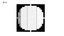
例えば、第2項Z2 は、図12に示すような分布を表し、瞳の左側の光経路の透過率と瞳の右側の光経路の透過率とが異なる状態を表す。すなわち、第2項はフォーカス値に依存して像の位置がずれる、いわゆるテレセンずれと似た影響力を持つ。したがって、第2項から、テレセンずれに関してある程度の予測を行える。 For example, the second term Z 2 represents a distribution as shown in FIG. 12, and represents a state in which the transmittance of the optical path on the left side of the pupil and the transmittance of the optical path on the right side of the pupil are different. That is, the second term has an influence similar to a so-called telecentric shift in which the image position shifts depending on the focus value. Therefore, from the second term, a certain degree of prediction about the telecentric deviation can be made.
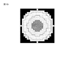
また、第4項は、図13に示すような同心円状の分布を表し、瞳の中央からの距離に応じて光経路の透過率が異なる状態を表す。回折光通過位置の瞳の中央からの距離は、マスクパターンの周期と関係するから、第4項から、マスクパターン周期に依存した最適露光量の変動についてある程度の予測を行える。 The fourth term represents a concentric distribution as shown in FIG. 13 and represents a state in which the transmittance of the optical path varies depending on the distance from the center of the pupil. Since the distance from the center of the pupil of the diffracted light passage position is related to the mask pattern period, a certain degree of prediction can be made from the fourth term regarding the variation of the optimum exposure amount depending on the mask pattern period.
以上述べたようなZernike多項式の展開係数に関する知見(物理的意味)は、マスクパターン設計において有用である。 The knowledge (physical meaning) regarding the expansion coefficient of the Zernike polynomial as described above is useful in mask pattern design.
次に、瞳透過率変動分布をZernike多項式展開して得られた展開係数を入力パラメータとして取り込み、計算機シミュレーションによって、瞳透過率変動を考慮した光学像を予測する。この予測はコンピューターのソフトウエア(プログラム)が行うから、瞳透過率変動の展開係数の情報を予め入力ファイルに保存しておき、シミュレータ(プログラム)が計算実行時に入力ファイルにアクセスして中の数値情報を読み取る。 Next, an expansion coefficient obtained by expanding the pupil transmittance variation distribution by Zernike polynomial expansion is taken as an input parameter, and an optical image in consideration of pupil transmittance variation is predicted by computer simulation. Since this prediction is performed by computer software (program), information on the expansion coefficient of pupil transmittance fluctuation is stored in the input file in advance, and the simulator (program) accesses the input file at the time of calculation and the numerical value in Read information.
入力ファイルの一例は、次の通りである。 An example of the input file is as follows.
ファイル名:input.txt
a1 1
a2 0.0194
a3 −0.0054
a4 0.0040
a5 −0.0202
a6 0.0110
a7 −0.0019
a8 −0.0074
a9 −0.0215
上記入力ファイルから係数a1〜a9の数値情報を読み取ったシミュレータ(プログラム)は、後述するウインドウ関数を計算する際(図14のステップS14)に、数(1)に従って瞳透過率変動T(ρ,φ)を計算する。
File name: input.txt
a2 0.0194
a3 -0.0054
a4 0.0040
a5 -0.0202
a6 0.0110
a7 -0.0019
a8 -0.0074
a9 -0.0215
The simulator (program) that reads the numerical information of the coefficients a1 to a9 from the input file calculates the pupil transmittance variation T (ρ,) according to the number (1) when calculating a window function described later (step S14 in FIG. 14 ). φ) is calculated.
図14に、上記光学像の予測方法を示すフローチャート、言い換えればシミュレータ(プログラム)のアルゴリズムの一例を示す。 FIG. 14 shows a flowchart showing the optical image prediction method, in other words, an example of a simulator (program) algorithm.
まず、二次光源中の任意の第1番目(k=1)の点光源の位置および輝度に関する情報を取得する(ステップS11,S12)。該情報の取得は、例えば、実測により行うか、もしくは露光装置の仕様値に基づいた計算により行う。 First, information on the position and brightness of an arbitrary first (k = 1) point light source in the secondary light source is acquired (steps S11 and S12). The information is acquired, for example, by actual measurement or by calculation based on the specification value of the exposure apparatus.
次に、上記一つの点光源の位置と輝度を考慮しながらマスクパターンfk(X,Y)をフーリエ変換し(Fk(ρ,φ))、投影光学系6の瞳上における光の振幅分布および位相分布を取得する(ステップS13)。ρおよびφは、それぞれ、投影光学系6の瞳上の極座標を定義する同径方向の長さおよび角度を示している。
Next, the mask pattern fk (X, Y) is Fourier transformed (Fk (ρ, φ)) in consideration of the position and brightness of the one point light source, and the light amplitude distribution on the pupil of the projection
次に、ステップS13にて得られたFk (A,φ)に、瞳座標依存性を持つ瞳透過率関数A(ρ、φ)を含んだウインドウ関数W(ρ、φ)を掛ける(ステップS14)。ウインドウ関数W(ρ,φ)は、投影光学系の瞳の大きさ、収差・瞳透過率変動の情報を含む関数である。収差(収差データ)は、ウインドウ関数W(ρ、φ)中のΦで表現される。 Next, the window function W (ρ, φ) including the pupil transmittance function A (ρ, φ) having pupil coordinate dependency is multiplied by F k (A, φ) obtained in step S13 (step S13). S14). The window function W (ρ, φ) is a function including information on the pupil size and aberration / pupil transmittance variation of the projection optical system. The aberration (aberration data) is expressed by Φ in the window function W (ρ, φ).
次に、ステップS14により得られた結果(Fk (ρ,φ)×ウインドウ関数)をフーリエ逆変換し、さらにこのフーリエ逆変換したものから、上記一つの点光源により作られる感光基板上の光の像強度分布を得る(ステップS15)。 Next, the result obtained in step S14 (F k (ρ, φ) × window function) is subjected to inverse Fourier transform, and further subjected to inverse Fourier transform to obtain light on the photosensitive substrate produced by the one point light source. Is obtained (step S15).
次に、ステップS15にて得られた像強度分布と、第1番目から第k−1番目までの光源が作る像強度分布の和とを、足し合わせる(ステップS16)。ここで、ステップS12において、k=1の場合、第1番目から第k−1番目までの光源が作る像強度分布の和は零とする。 Next, the image intensity distribution obtained in step S15 and the sum of image intensity distributions created by the first to (k−1) th light sources are added (step S16). Here, in step S12, when k = 1, the sum of the image intensity distributions created by the first to (k−1) th light sources is zero.
そして、k=nに達するまで、ステップS12〜S16を繰り返すことで(ステップS17,S18)、二次光源中のn個の点光源により作られる像強度分布を足し合わすことにより、感光基板7上の光学像を計算することができる。
Then, steps S12 to S16 are repeated until k = n is reached (steps S17 and S18), and the image intensity distributions formed by the n point light sources in the secondary light sources are added together, thereby obtaining the image on the
なお、ステップ16の像強度分布を足し合わせは、後でまとめて行っても構わない。すなわち、ステップS12〜S15を繰り返し、二次光源中のk=1〜nに対応したn個の像強度分布を求めてから、n個の像強度分布を足し合わせることでも、感光基板7上の光学像は得られる。
Note that the image intensity distributions in step 16 may be added together later. That is, steps S12 to S15 are repeated to obtain n image intensity distributions corresponding to k = 1 to n in the secondary light source, and then the n image intensity distributions are added together to obtain the image on the
ここでは、光学像を予測したが、レジストパターンを予測しても構わない。レジストパターンを予測する方法の一例としては、図14のフローに従って計算した光学像と、プロセスファクタを含んだ指数型減衰関数との畳み込み積分により予測する周知の方法、例えば、特開平8−148404の第1の実施の形態(段落番号0020〜0035)がある。 Here, an optical image is predicted, but a resist pattern may be predicted. As an example of a method for predicting a resist pattern, a well-known method for predicting by convolution integration of an optical image calculated according to the flow of FIG. 14 and an exponential decay function including a process factor, for example, Japanese Patent Laid-Open No. 8-148404. There is a first embodiment (paragraph numbers 0020-0035).
また、ここでは、投影光学系の透過率変動を近似する直交多項式として、Zernike多項式を用いたが、透過率変動を少ない展開係数で近似することができるのであれば、他の直交多項式を用いても構わない。 Here, the Zernike polynomial is used as an orthogonal polynomial that approximates the transmittance variation of the projection optical system. However, if the transmittance variation can be approximated with a small expansion coefficient, another orthogonal polynomial is used. It doesn't matter.
(第5の実施形態)
図15は、第5の実施形態のマスクパターンの形成方法を示すフローチャートである。
(Fifth embodiment)
FIG. 15 is a flowchart showing a mask pattern forming method according to the fifth embodiment.
まず、露光装置の収差特性(レンズの収差)および瞳透過率変動特性を周知の方法により計測し、それらの計測データ(収差データ、瞳透過率変動データ)から、収差特性と瞳透過率変動特性をZernike多項式展開し、展開係数を取得する(ステップS21)。 First, the aberration characteristics (lens aberration) and pupil transmittance fluctuation characteristics of the exposure apparatus are measured by a well-known method, and the aberration characteristics and pupil transmittance fluctuation characteristics are obtained from these measurement data (aberration data, pupil transmittance fluctuation data). Zernike polynomials are expanded to obtain expansion coefficients (step S21).
次に、露光装置のレンズに収差および瞳透過率変動がないとして設計したマスクパターンのデータ(マスクパターンデータ)を作成する(ステップS22)。 Next, mask pattern data (mask pattern data) designed on the assumption that the lens of the exposure apparatus has no aberration and no pupil transmittance variation is created (step S22).
次に、マスクパターンデータ、収差データおよび瞳透過率変動データに基づいて、感光基板上に形成される光学像を予測する(ステップS23)。光学像は、マスクパターンデータ、収差データおよび瞳透過率変動データを用いて第4の実施形態の方法に従って光学像を計算し、予測することができる。 Next, an optical image formed on the photosensitive substrate is predicted based on the mask pattern data, aberration data, and pupil transmittance fluctuation data (step S23). An optical image can be predicted by calculating an optical image according to the method of the fourth embodiment using mask pattern data, aberration data, and pupil transmittance fluctuation data.
次に、ステップ23で予測した光学像と、感光基板上に形成されるべき設計上の光学像とを比較する(ステップS24)。
Next, the optical image predicted in
その結果、二つの計算結果の差異(光学像の差違)が許容範囲外の場合には、マスクパターン中のパターンについて、差異が減少するようにパターンデータを変更し、新たにマスクパターンデータを作成する(ステップS25)。 As a result, if the difference between the two calculation results (difference in optical image) is outside the allowable range, the pattern data in the mask pattern is changed so that the difference decreases, and new mask pattern data is created. (Step S25).
そして、ステップS23に戻って再度光学像を計算し、ステップ24で算出する差異が許容範囲内になるまでステップS23〜S25を繰り返し適用し、差異が許容範囲内となるマスクパターンデータが求められたら、そのマスクパターンデータを用いてフォトマスクを製造する(ステップS26)。また、ステップS24の判定で光学像の差違が許容範囲内の場合もステップS26に進む。
Then, returning to step S23, the optical image is calculated again, and steps S23 to S25 are repeatedly applied until the difference calculated in
また、第4の実施形態の予測方法や第5の実施形態の設計方法は、コンピュータに所定の手段を実行させるための(あるいはコンピュータを所定の手段として機能させるための、あるいはコンピュータに所定の機能を実現させるための)プログラムとして実施することもでき、さらに該プログラムを記録したコンピュータ読取り可能な記録媒体として実施することもできる。 The prediction method of the fourth embodiment and the design method of the fifth embodiment are for causing a computer to execute predetermined means (or for causing a computer to function as predetermined means, or for causing a computer to have predetermined functions). The program can be implemented as a computer-readable recording medium on which the program is recorded.
なお、本発明は、上記実施形態に限定されるものではない。例えば、上記実施形態には種々の段階の発明が含まれており、開示される複数の構成要件における適宜な組み合わせにより種々の発明が抽出され得る。例えば、実施形態に示される全構成要件から幾つかの構成要件が削除されても、発明が解決しようとする課題の欄で述べた課題を解決できる場合には、この構成要件が削除された構成が発明として抽出され得る。 The present invention is not limited to the above embodiment. For example, the above embodiments include inventions at various stages, and various inventions can be extracted by appropriately combining a plurality of disclosed constituent elements. For example, even if some constituent requirements are deleted from all the constituent requirements shown in the embodiment, if the problem described in the column of the problem to be solved by the invention can be solved, the configuration in which this constituent requirement is deleted Can be extracted as an invention.
その他、本発明の要旨を逸脱しない範囲で、種々変形して実施できる。 In addition, various modifications can be made without departing from the scope of the present invention.
1…照明光学系、2…フライアレイレンズ、3…照明アパーチャ(二次光源面)、4…コンデンサレンズ、5…フォトマスク、6…投影光学系、7…感光基板上(ウェハ)、11…第1のL&Sパターン、12…第2のL&Sパターン、21〜23…第1の回折光の光路、24〜26…第2の回折光の光路、L1〜L3,L1’〜L3’…回折光、M11〜M13…マスクパターン、P11〜P13,P21〜P23…一括露光領域内の領域、
P11’〜P13’…感光基板上の領域。
DESCRIPTION OF
P11 ′ to P13 ′: regions on the photosensitive substrate.
Claims (6)
前記投影光学系を通過する光の前記投影光学系内の経路の違いに依存して変化する、前記投影光学系の透過率変動を、前記投影光学系の瞳座標で定義される直交多項式を用いて近似する第一工程と、
前記二次光源中の複数の点光源を決める第二工程と、
前記複数の点光源のうちの一つから発する光が前記フォトマスクに照射されて、前記マスクパターン通過後に発生する回折光の前記投影光学系内の経路を計算する第三工程と、
前記経路を通過する各々の回折光に関して、前記投影光学系の透過率変動を近似する前記直交多項式の展開係数に基づいて光強度の減衰を与える第四工程と、
前記各々の回折光が感光基板上に形成する像強度分布を計算する第五工程と、
前記複数の点光源の残りのすべての点光源に対して、前記第三工程から第五工程までを実施し、前記複数の点光源の各々から得られた像強度分布を足し合わせて一つの像強度分布を求める第六工程と、
前記第六工程で求めた像強度分布に基づいて、前記パターンを予測する第七工程と
を有することを特徴とするパターン予測方法。 Pattern prediction for predicting a pattern on the photosensitive substrate formed by irradiating a photomask with light emitted from a secondary light source and condensing the light that has passed through the photomask onto a photosensitive substrate through a projection optical system A method,
Using the orthogonal polynomial defined by the pupil coordinates of the projection optical system, the transmittance variation of the projection optical system that changes depending on the path in the projection optical system of the light passing through the projection optical system A first step that approximates
A second step of determining a plurality of point light sources in the secondary light source;
A third step of calculating a path in the projection optical system of the diffracted light generated after the light emitted from one of the plurality of point light sources is irradiated on the photomask and passed through the mask pattern;
For each diffracted light passing through the path, a fourth step of attenuating light intensity based on the expansion coefficient of the orthogonal polynomial that approximates the transmittance variation of the projection optical system;
A fifth step of calculating an image intensity distribution formed on the photosensitive substrate by each diffracted light;
The third step to the fifth step are performed on all remaining point light sources of the plurality of point light sources, and an image intensity distribution obtained from each of the plurality of point light sources is added to form one image. A sixth step for obtaining an intensity distribution;
And a seventh step of predicting the pattern based on the image intensity distribution obtained in the sixth step .
前記投影光学系を通過する光の前記投影光学系内の経路の違いに依存して変化する、前記投影光学系の透過率変動を、前記投影光学系の瞳座標で定義される直交多項式を用いて近似させる第一手順と、
前記二次光源中の複数の点光源を決めさせる第二手順と、
前記複数の点光源のうちの一つから発する光が前記フォトマスクに照射されて、前記マスクパターン通過後に発生する回折光の前記投影光学系内の経路を計算させる第三手順と、
前記経路を通過する各々の回折光に関して、前記投影光学系の透過率変動を近似する前記直交多項式の展開係数に基づいて光強度の減衰を与えさせる第四手順と、
前記各々の回折光が感光基板上に形成する像強度分布を計算させる第五手順と、
前記複数の点光源の残りのすべての点光源に対して、前記第三手順から第五手順までを実施させ、前記複数の点光源の各々から得られた像強度分布を足し合わせて一つの像強度分布を求めさせる第六手順と、
前記第六手順で求めさせた像強度分布に基づいて、前記パターンを予測させる第七手順と
を実行させるためのプログラム。 Predict the pattern on the photosensitive substrate formed by irradiating the computer with light emitted from a secondary light source on the photomask and condensing the light that has passed through the photomask onto the photosensitive substrate via the projection optical system A program for executing the procedure
Using the orthogonal polynomial defined by the pupil coordinates of the projection optical system, the transmittance variation of the projection optical system that changes depending on the path in the projection optical system of the light passing through the projection optical system The first step to approximate
A second procedure for determining a plurality of point light sources in the secondary light source;
A third step of irradiating the photomask with light emitted from one of the plurality of point light sources and calculating a path in the projection optical system of diffracted light generated after passing through the mask pattern;
For each diffracted light passing through the path, a fourth procedure for giving light intensity attenuation based on the expansion coefficient of the orthogonal polynomial that approximates the transmittance variation of the projection optical system;
A fifth procedure for calculating an image intensity distribution formed on the photosensitive substrate by each diffracted light;
The third procedure to the fifth procedure are performed on all remaining point light sources of the plurality of point light sources, and the image intensity distribution obtained from each of the plurality of point light sources is added to form one image. A sixth procedure for determining the intensity distribution;
A program for executing the seventh procedure for predicting the pattern based on the image intensity distribution obtained in the sixth procedure .
Priority Applications (1)
| Application Number | Priority Date | Filing Date | Title |
|---|---|---|---|
| JP2007038646A JP4131981B2 (en) | 2007-02-19 | 2007-02-19 | Pattern prediction method and program |
Applications Claiming Priority (1)
| Application Number | Priority Date | Filing Date | Title |
|---|---|---|---|
| JP2007038646A JP4131981B2 (en) | 2007-02-19 | 2007-02-19 | Pattern prediction method and program |
Related Parent Applications (1)
| Application Number | Title | Priority Date | Filing Date |
|---|---|---|---|
| JP2002287363A Division JP4077288B2 (en) | 2002-09-30 | 2002-09-30 | Photomask design method and program |
Publications (2)
| Publication Number | Publication Date |
|---|---|
| JP2007150354A JP2007150354A (en) | 2007-06-14 |
| JP4131981B2 true JP4131981B2 (en) | 2008-08-13 |
Family
ID=38211277
Family Applications (1)
| Application Number | Title | Priority Date | Filing Date |
|---|---|---|---|
| JP2007038646A Expired - Fee Related JP4131981B2 (en) | 2007-02-19 | 2007-02-19 | Pattern prediction method and program |
Country Status (1)
| Country | Link |
|---|---|
| JP (1) | JP4131981B2 (en) |
Families Citing this family (1)
| Publication number | Priority date | Publication date | Assignee | Title |
|---|---|---|---|---|
| NL2003654A (en) * | 2008-11-06 | 2010-05-10 | Brion Tech Inc | Methods and system for lithography calibration. |
-
2007
- 2007-02-19 JP JP2007038646A patent/JP4131981B2/en not_active Expired - Fee Related
Also Published As
| Publication number | Publication date |
|---|---|
| JP2007150354A (en) | 2007-06-14 |
Similar Documents
| Publication | Publication Date | Title |
|---|---|---|
| KR100839972B1 (en) | Lithographic apparatus and device manufacturing method | |
| KR100899359B1 (en) | A method, program product and apparatus for performing double exposure lithography | |
| JP4425239B2 (en) | Lithographic apparatus and device manufacturing method | |
| JP4102728B2 (en) | Automatic optical proximity correction (OPC) rule creation | |
| US8365106B2 (en) | Method for optimization of light effective source while target pattern is changed | |
| EP1473596A2 (en) | Lithographic apparatus and method for optimizing an illumination source using photolithographic simulations | |
| US7927773B2 (en) | Memory medium storing original data generation program, memory medium storing illumination condition determination program, original data generation method, illumination condition determination method, and device manufacturing method | |
| JP4804294B2 (en) | Master data creation program, master data creation method, master creation method, exposure method, and device manufacturing method | |
| US8043797B2 (en) | Lithographic apparatus and device manufacturing method | |
| JP4398852B2 (en) | Method for adjusting mask pattern transmittance to improve process latitude | |
| US8247141B2 (en) | Method of generating reticle data, memory medium storing program for generating reticle data and method of producing reticle | |
| JP4077288B2 (en) | Photomask design method and program | |
| US8234600B2 (en) | Computer readable storage medium storing program for generating reticle data, and method of generating reticle data | |
| CN107450277B (en) | Specifying method, information processing apparatus, exposure apparatus, and article manufacturing method | |
| US10545413B2 (en) | Evaluation method, exposure method, and method for manufacturing an article | |
| JP4131981B2 (en) | Pattern prediction method and program | |
| JP5539140B2 (en) | Determination method, exposure method, program, and computer | |
| CN115629517A (en) | OPC correction method | |
| US20120163699A1 (en) | Mask determination method, exposure method, and semiconductor device manufacturing method |
Legal Events
| Date | Code | Title | Description |
|---|---|---|---|
| A131 | Notification of reasons for refusal |
Free format text: JAPANESE INTERMEDIATE CODE: A131 Effective date: 20080129 |
|
| A521 | Written amendment |
Free format text: JAPANESE INTERMEDIATE CODE: A523 Effective date: 20080328 |
|
| TRDD | Decision of grant or rejection written | ||
| A01 | Written decision to grant a patent or to grant a registration (utility model) |
Free format text: JAPANESE INTERMEDIATE CODE: A01 Effective date: 20080527 |
|
| A01 | Written decision to grant a patent or to grant a registration (utility model) |
Free format text: JAPANESE INTERMEDIATE CODE: A01 |
|
| A61 | First payment of annual fees (during grant procedure) |
Free format text: JAPANESE INTERMEDIATE CODE: A61 Effective date: 20080529 |
|
| FPAY | Renewal fee payment (event date is renewal date of database) |
Free format text: PAYMENT UNTIL: 20110606 Year of fee payment: 3 |
|
| FPAY | Renewal fee payment (event date is renewal date of database) |
Free format text: PAYMENT UNTIL: 20110606 Year of fee payment: 3 |
|
| FPAY | Renewal fee payment (event date is renewal date of database) |
Free format text: PAYMENT UNTIL: 20120606 Year of fee payment: 4 |
|
| FPAY | Renewal fee payment (event date is renewal date of database) |
Free format text: PAYMENT UNTIL: 20120606 Year of fee payment: 4 |
|
| FPAY | Renewal fee payment (event date is renewal date of database) |
Free format text: PAYMENT UNTIL: 20130606 Year of fee payment: 5 |
|
| LAPS | Cancellation because of no payment of annual fees |
