JP4131510B2 - Resistance value selection method for brushless motor device - Google Patents
Resistance value selection method for brushless motor device Download PDFInfo
- Publication number
- JP4131510B2 JP4131510B2 JP2001348113A JP2001348113A JP4131510B2 JP 4131510 B2 JP4131510 B2 JP 4131510B2 JP 2001348113 A JP2001348113 A JP 2001348113A JP 2001348113 A JP2001348113 A JP 2001348113A JP 4131510 B2 JP4131510 B2 JP 4131510B2
- Authority
- JP
- Japan
- Prior art keywords
- phase
- brushless motor
- motor
- magnetic flux
- resistance value
- Prior art date
- Legal status (The legal status is an assumption and is not a legal conclusion. Google has not performed a legal analysis and makes no representation as to the accuracy of the status listed.)
- Expired - Fee Related
Links
Images


Landscapes
- Control Of Motors That Do Not Use Commutators (AREA)
Description
【0001】
【発明の属する技術分野】
本発明は、スイッチング手段の内部抵抗と配線の抵抗とが原因となる駆動電圧の降下を小さくするブラシレスモータ装置に関する。
【0002】
【従来の技術】
モータは、様々な産業分野で利用されている。小さなモータは、例えば、携帯電話、テープレコーダあるいはDVD等に使用されている。直径が数mの大きなモータは、例えば、圧延機用モータとして使用されている。
【0003】
モータには、整流子モータ、誘導モータ、ブラシレスモータ等の種類がある。
【0004】
整流子モータは、ブラシと、整流子と、コイルとを含む。整流子モータは、構造が簡単で直流あるいは交流の何れの電流でも使えるために、高精度を必要としない汎用小型機器、家電製品、玩具などに広く使われている。
【0005】
誘導モータは、磁場が回転し、そのときに起こる電磁誘導によって生成される電流によりモータを回転する。誘導モータは、鉄鋼の圧延機や、製紙ロール器等の工業生産用モータとして使われている。
【0006】
ブラシレスモータは、整流子モータの構成要素であるブラシや整流子などの機械的な摺動部の代わりにセンサや専用ICを使ってモータの整流機構を実現している。ブラシレスモータは、ブラシと整流子とを備えていないためブラシと整流子との接触が無く、そのため摩擦が無いので長寿命であり、金属粉やカーボンも飛散しない。ブラシレスモータは、パソコンのハードディスクドライブ、CD−ROMドライブ、空冷用のファンなどに使われている。
【0007】
【発明が解決しようとする課題】
従来、Y字型に結線された3相コイルを有するブラシレスモータ(Y結線3相ブラシレスモータ)は知られていたが、デルタ型に結線された3相コイルを有するブラシレスモータ(デルタ結線3相ブラシレスモータ)は存在しなかった。デルタ型結線は、もっぱら整流子モータや誘導モータに利用されていたからである。 本発明は、従来のY結線3相ブラシレスモータ装置より優れた性能を有するデルタ結線3相ブラシレスモータ装置を提供することを目的とする。
【0008】
【課題を解決するための手段】
本発明による半導体発光素子は、デルタ型に結線された3相のコイルを含むモータ手段と、配線を介して前記モータ手段に電気的に接続されたスイッチング手段と、前記スイッチング手段のオンオフを制御することにより、前記モータ手段を駆動する駆動手段とを備えたブラシレスモータ装置において、前記スイッチング手段がオン時の前記スイッチング手段の内部抵抗の値をr1、前記配線の抵抗の値をr2、前記3相のコイルのそれぞれの直流抵抗の値をRとするときの前記各抵抗値r1、r2、2Rの抵抗値選択方法であって、前記各抵抗値r1、r2、2Rを、r1+r2<2Rが成立するように選択することを特徴とし、これにより上記目的が達成される。
【0009】
前記駆動手段は、前記スイッチング手段がオンの時間と前記スイッチング手段がオフの時間との比を可変に制御してもよい。
【0010】
前記モータ手段は、軸の周りに回転可能なロータをさらに含み、
前記駆動手段は、前記スイッチング手段が前記ロータの回転角に応じた正弦波電流を出力するように該スイッチング手段のオンオフを制御してもよい。
【0011】
前記モータ手段と前記スイッチング手段とは一体に構成されていてもよい。
【0012】
前記モータ手段は、前記ロータが発生する磁束を検出する磁束検出手段をさらに含み、前記磁束検出手段は、前記3相のコイルのうち隣接する2つのコイルが発生する磁束が互いに打ち消しあう位置に設置されていてもよい。
【0013】
前記モータ手段は、前記ロータが発生する磁束を検出する磁束検出手段をさらに含み、前記駆動手段は、前記正弦波電流の位相と前記磁束検出手段によって検出される前記ロータの回転角の位相との差が一定となるように前記スイッチング手段のオンオフを制御してもよい。
【0014】
前記モータ手段は、前記ロータが発生する磁束を検出する磁束検出手段をさらに含み、前記駆動手段は、前記正弦波電流の位相と前記磁束検出手段によって検出される前記ロータの回転角の位相との差が前記ロータの回転速度に基づいて可変となるように前記スイッチング手段のオンオフを制御してもよい。
【0015】
【発明の実施の形態】
以下、図1、図2、図3A〜図3Cおよび図4A〜図4Cを参照して本発明の実施の形態を説明する。
【0016】
1.ブラシレスモータ装置の構成
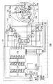
図1は、本発明の実施の形態におけるブラシレスモータ装置100の構成を示す。
【0017】
ブラシレスモータ装置100は、デルタ型に結線された3相のコイルを含むモータ手段としてのブラシレスモータ110と、配線を介してブラシレスモータ110に電気的に接続されたスイッチング手段140と、スイッチング手段140のオンオフを制御することによりブラシレスモータ110を駆動する駆動手段130とを含む。
【0018】
ブラシレスモータ110は、軸の周りに回転可能なロータ112と、ロータに対して固定した位置に設置されているステータコイル114と、ロータ112が発生する磁束を検出する磁束検出手段(ホール素子)116とを含む。
【0019】
ロータ112は、磁性体である(以下、ロータマグネット112という)。図1に示される例では、ロータマグネット112は、4極着磁ロータマグネットである。しかし、ロータマグネット112の極数は4に限定されない。ロータマグネット112は、例えば、12極着磁ロータマグネットであってもよい。
【0020】
ステータコイル114は、第1相のコイル114aと、第2相のコイル114bと、第3相のコイル114cとを含む。第1相のコイル114aの第1の端子Ta1と第2相のコイル114bの第1の端子Tb1とは電気的に接続される。第2相のコイル114bの第2の端子Tb2と第3相のコイル114cの第1の端子Tc1とは電気的に接続される。第3相のコイル114cの第2の端子Tc2と第1相のコイル114aの第2の端子Ta2とは電気的に接続される。このように、第1相のコイル114aと、第2相のコイル114bと、第3相のコイル114cとは、デルタ型に結線される。
【0021】
図1に示される例では、ステータコイル114は、3極3相ステータコイルである。しかし、ステータコイル114の極数は3に限定されない。ステータコイル114は、例えば、9極3相ステータコイルであってもよい。
【0022】
ホール素子116は、ロータマグネット112が発生する磁束を検出する。ホール素子116は、検出された磁束に基づいて、ロータマグネット112の回転角に応じた正弦波信号を出力する。この出力信号は、ホールアンプ/2値化手段131に入力される。
【0023】
図1では、ホール素子116は、第2相のコイル114bから第1相のコイル114aの方向に30°進んだ位置に引かれた一点鎖線からさらに15°だけ第1相のコイル114aの方向に進んだ位置であって、第1相のコイル114aから第2相のコイル114bの方向に75°進んだ位置に備えられている。つまり、ホール素子116は、第2相のコイル114bから第1相のコイル114aの方向に45°進んだ位置であって、第1相のコイル114aから第2相のコイル114bの方向に75°進んだ位置に備えられている。
【0024】
スイッチング手段140は、3個の上側スイッチング素子HA1、HA2、HA3と、3個の下側スイッチング素子LA1、LA2、LA3と、3個の上側ダイオードHD1、HD2、HD3と、3個の下側ダイオードLD1、LD2、LD3を含む。
【0025】
スイッチング手段140が含むスイッチング素子HA1、LA1、HA2、LA2、HA3およびLA3は、後述するように駆動手段130によって生成される出力信号H1、L1、H2、L2、H3およびL3に基づいて駆動される。
【0026】
駆動手段130は、スイッチング手段140のオンとオフとを制御することで、電圧5Vの電源からステータコイル114に流れる電流を制御する。
【0027】
駆動手段130は、ホールアンプ/2値化手段131と、パルス間隔計測手段132と、正弦波テーブル格納部133と、換算器134と、Data−Duty変換手段135と、駆動回路136と、起動手段137と、逆起電圧検出手段138と、制御手段139とを含む。
【0028】
ホールアンプ/2値化手段131は、ホール素子116の出力信号を増幅した後、この増幅した出力信号に基づいて2値化パルス信号を生成する。この2値化パルス信号は、ホールアンプ/2値化手段131から出力され、パルス間隔計測手段132と正弦波テーブル格納部133とに入力される。
【0029】
パルス間隔計測手段132は、ホールアンプ/2値化手段131から出力された2値化パルス信号のパルスの立上がり部分の時間間隔を計測する。パルス間隔計測手段132は、計測した時間間隔を表す測定デジタルデータを正弦波テーブル格納部133に出力する。また、パルス間隔計測手段132は、ブラシレスモータ110の実際の回転速度を示す回転速度信号FGをホールアンプ/2値化手段131から出力された2値化パルス信号に基づいて生成する。パルス間隔計測手段132は、生成された回転速度信号FGを制御手段139に出力する。
【0030】
正弦波テーブル格納部133は、正弦波の角度に対応する正弦値を表したテーブルを格納している。このテーブルのデータ構成を(表1)に示す。
【0031】
【表1】
【0032】
例えば、データ番号No.32の正弦波の位相は90°であり、系列Hの正弦値は254、系列Lの正弦値は0である。例えば、データ番号No.96の正弦波の位相は270°であり、系列Hの正弦値は0、系列Lの正弦値は255である。
【0033】
図2は、図1に示される正弦波テーブル格納部133に格納されたテーブル(表1)の値を示す。縦軸は、正弦値を示す。横軸は、データ番号を示す。系列Hのデータは、●印でプロットしている。系列Lのデータは、▲印でプロットしている。
【0034】
データ番号がNo.0からNo.63(正弦波の位相が0°から180°)までの場合は、系列Hの値は、正弦波の位相に対応する正弦値である。系列Lの値は、0である。
【0035】
データ番号がNo.64からNo.127(正弦波の位相が180°から360°)までの場合は、系列Hの値は、0である。系列Lの値は、正弦波の位相に対応する正弦値の絶対値である。
【0036】
正弦波テーブル格納部133は、ホールアンプ/2値化手段131から出力された2値化パルス信号のパルスの立ち上がりに応じて、格納されたテーブルの値を読み出す。正弦波テーブル格納部133は、パルス間隔計測手段132の出力時間の間隔と同じ間隔で、正弦波の1周期分のデータ数である128個のデータを読み出す。正弦波テーブル格納部133は、3つの異なるデータ番号から読み出しを開始することで、合計6個の信号Hp1、Lp1、Hp2、Lp2、Hp3およびLp3を出力する。H系列の出力信号Hp1は、L系列の出力信号Lp1と同じデータ番号である。H系列の出力信号Hp2は、L系列の出力信号Lp2と同じデータ番号である。H系列の出力信号Hp3は、L系列の出力信号Lp3と同じデータ番号である。
【0037】
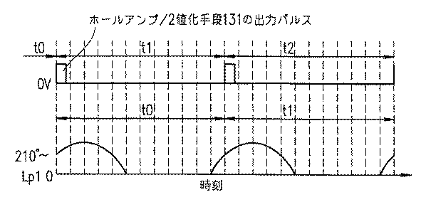
図3Aは、ホール素子116が出力する正弦波信号とホールアンプ/2値化手段131の出力パルスを示す。縦軸は、出力の大きさを示す。横軸は、時刻を示す。この出力パルスは、ホール素子116が出力する正弦波信号が負から正に変化する時刻に立ち上がるパルスである。
【0038】
パルス間隔計測手段132は、パルスの間隔を計測し、時間データt0、t1、t2・・・を生成する。
【0039】
図3Bは、正弦波テーブル格納部133から出力された出力信号Hp1、Lp1、Hp2、Lp2、Hp3およびLp3を示す。縦軸は、出力信号の大きさを示す。横軸は、時刻を示す。
【0040】
正弦波テーブル格納部133は、ホールアンプ/2値化手段131から出力されたパルスを入力すると、正弦波テーブル格納部133に格納されたテーブルのNo.75のH系列の値からH系列の値を読み出し始め、この値を出力信号Hp1として掛算器134に出力する。No.127のH系列の値まで出力するとNo.0に戻り、同様にH系列の値の読み出しを繰り返す。読み出しの値がNo.1まで来ると、H系列の値12、24、37...が、出力信号Hp1として順に出力される。
【0041】
読み出しの速度は、ホールアンプ/2値化手段131の出力パルス間隔t0で128個のデータを出力する速度に制御される。出力の途中でホールアンプ/2値化手段131から次のパルスが出力されると、最初のNo.75に戻り、読み出しの速度は、ホールアンプ/2値化手段131の出力パルス間隔t1で128個のデータを出力する速度に制御される。
【0042】
同様に、正弦波テーブル格納部133に格納されたテーブルのL系列のNo.75の値から読み出しを開始し、この値を出力信号Lp1として掛算器134に出力する。
【0043】
同様に、正弦波テーブル格納部133に格納されたテーブルのH系列のNo.117の値から読み出しを開始し、この値を出力信号Hp2として掛算器134に出力する。
【0044】
同様に、正弦波テーブル格納部133に格納されたテーブルのL系列のNo.117の値から読み出しを開始し、この値を出力信号Lp2として掛算器134に出力する。
【0045】
同様に、正弦波テーブル格納部133に格納されたテーブルのH系列のNo.32の値から読み出しを開始し、この値を出力信号Hp3として掛算器134に出力する。
【0046】
同様に、正弦波テーブル格納部133に格納されたテーブルのL系列のNo.32の値から読み出しを開始し、この値を出力信号Lp2として掛算器134に出力する。
【0047】
図3Cは、ステータコイル114の第1相のコイル114aと、第2相のコイル114bと、第3相のコイル114cとに各々印加される電圧Va,Vb,Vcを示す。
【0048】
電圧Va,Vb,Vcは、ホール素子116の出力信号と同じ周波数で一定の位相関係を持つ。
【0049】
掛算器134は、制御手段139から出力される電圧指令値Vdを正弦波テーブル格納部133から出力される出力信号Hp1、Lp1、Hp2、Lp2、Hp3およびLp3に各々掛けることで、出力信号Hq1、Lq1、Hq2、Lq2、Hq3およびLq3を生成する。
【0050】
電圧指令値Vdは、ブラシレスモータ110を駆動する電圧の指令値である。後述するように、制御手段139は、8bit(0から255まで)のデータ値として電圧指令値Vdを出力する。電圧指令値0Vの場合、データ値0が出力される。電圧指令値5Vの場合、データ値255が出力される。
【0051】
正弦波テーブル格納部133から出力された出力信号Hp1、Lp1、Hp2、Lp2、Hp3およびLp3の値の最高値は、255である。したがって、出力信号Hq1、Lq1、Hq2、Lq2、Hq3およびLq3の最高値は、255×255=65025である。
【0052】
Data−Duty変換手段135は、出力信号Hq1、Lq1、Hq2、Lq2、Hq3およびLq3をこれらの出力信号の値に比例したduty比を持つ出力信号Hr1、Lr1、Hr2、Lr2、Hr3およびLr3に変換する。最高値65025である出力信号は、duty比=100%である。最低値0である出力信号は、duty比=0%である。
【0053】
駆動回路136は、出力信号Hr1、Lr1、Hr2、Lr2、Hr3およびLr3を入力し、出力信号H1、L1、H2、L2、H3およびL3を生成する。スイッチング手段140が含むスイッチング素子HA1、LA1、HA2、LA2、HA3およびLA3は、出力信号H1、L1、H2、L2、H3およびL3に基づいて駆動される。また、後述するように駆動回路136は、起動手段137からも信号を入力する。後述するように駆動回路136は、制御手段139から切り替え信号を入力する。
【0054】
逆起電圧検出手段138は、ステータコイル114に発生する逆起電圧の位相に関するデータ、極性に関するデータ等を検出し、これらのデータを起動手段137に出力する。
【0055】
起動手段137は、ロータマグネット112に回転運動を与えるために、ブラシレスモータ110の起動時に適当な信号を駆動回路136に出力する。起動手段137は、逆起電圧検出手段138から出力されるデータを入力し、駆動回路136に出力する。駆動回路136は、逆起電圧検出手段138から出力されるデータに基づいて、ブラシレスモータ110を低い回転数で駆動することができる。
【0056】
駆動回路136は、信号L1、L2およびL3を各々下側スイッチング素子LA1、LA2およびLA3に出力する。駆動回路136は、信号H1、H2およびH3を各々上側スイッチング素子HA1、HA2およびHA3に出力する。駆動回路136は、スイッチング手段140のオンとオフとを制御することで、電圧5Vの電源からステータコイル114に流れる電流を制御する。
【0057】
上側スイッチング素子HA1、HA2およびHA3ならびに下側スイッチング素子LA1、LA2およびLA3は、完全にオンまたは完全にオフの動作のみを行う。したがって、オン状態のスイッチング素子には、電流‐電圧特性が飽和状態になるような十分な電圧を印加できる。
【0058】
また、スイッチング手段140とブラシレスモータ110とは、一体に構成されることにより、スイッチング手段140とステータコイル114の間の配線の抵抗を低くすることができる。
【0059】
制御手段139は、速度指令値、速度信号FGおよびSTART/STOP信号を入力する。制御手段139は、ブラシレスモータ110の起動時に駆動回路136および起動手段137へ切替信号を出力する。制御手段139は、速度信号FGを入力することでブラシレスモータ110の回転数がある一定以上になったことを検出すると、駆動回路136を通常の駆動に切り替える。また、制御手段139は、速度指令値の信号と速度信号FGとを比較し、この差に比例した値を電圧指令値Vdとして出力する。ブラシレスモータ110の回転数が速度指令値の値になるように、ブラシレスモータ110が制御される。
【0060】
2.ブラシレスモータ装置100の動作
以下に、ブラシレスモータ装置100の動作を説明する。本発明の実施の形態におけるブラシレスモータ装置100は、例えば光ディスク記録再生装置に備えて利用される。
【0061】
START信号が制御手段139に入力されると、制御手段139は、駆動回路136および起動手段137に切替信号を出力する。起動手段137から出力された信号によって、ブラシレスモータ110は、駆動状態になる。起動手段137は、適当な信号を駆動回路136に出力し、スイッチング手段140を制御することで、ロータマグネット112に回転運動を与える。
【0062】
制御手段139が速度信号FGによりロータマグネット112に回転運動が与えらたことを検出すると、制御手段139は、起動手段137に切替信号を出力する。起動手段137は、逆起電力検出手段138から出力されるステータコイル114に発生する逆起電圧の位相に関するデータ、極性に関するデータに基づいて生成された信号を駆動回路136に出力する。駆動回路136は、スイッチング手段140を制御することでブラシレスモータ110を低い回転数で駆動する。駆動回路136は、回転数が上昇し回転数が一定以上に成ると通常の駆動に切り替わり、出力信号Hr1、Lr1、Hr2、Lr2、Hr3およびLr3に基づいて駆動を行う。
【0063】
ブラシレスモータ110は、すでに所定の回転数以上で回転しているので、ホール素子116から安定した出力信号が出力される。ホールアンプ/2値化手段131は、2値化信号を出力する。パルス間隔計測手段132は、ホールアンプ/2値化手段131から出力されたパルスの立上がり部分の時間間隔を計測し、計測デジタルデータが出力される。計測デジタルデータは、正弦波テーブル格納部133に入力され、出力信号Hp1、Lp1、Hp2、Lp2、Hp3およびLp3が出力される。
【0064】
正弦波テーブル格納部133は、ホールアンプ/2値化手段131から出力されたパルス信号の立上がり時刻に読み出しを開始し、パルス間隔計測手段132のパルス信号出力間隔と同じ時間間隔で128個のデータを読み出す。このため、ブラシレスモータ110が定速回転している場合、ホール素子116の出力信号の周期と正弦波テーブル格納部133から読み出されるデータの周期は一致する。また、ホール素子116の出力信号の位相と正弦波テーブル格納部133から読み出されるデータの位相も、互いに一定の関係を持つ。
【0065】
パルス間隔計測手段132から出力された時間間隔のデータは、1周期前の時間間隔のデータであるため、ブラシレスモータ110が加減速している場合は、ホール素子116の出力信号の周期と正弦波テーブル格納部133から読み出されるデータの周期は一致せず、また、ホール素子116の出力信号の位相と正弦波テーブル格納部133から読み出されるデータの位相も、互いに一定の関係を成さない。しかし、12極着磁ロータマグネットと9極3相のステータコイルを備えたブラシレスモータ装置では、ホール素子116の出力信号は12極着磁ロータマグネットの1/6回転で1周期の信号を発生する。12極着磁ロータマグネットを500r.p.m程度以上で回転させ、最大トルクで加減速した場合でも、周期の不一致は最大10%程度で、ブラシレスモータ装置の性能には、全く問題はない。
【0066】
掛算器134は、制御手段139から出力された電圧指令値Vdを出力信号Hp1、Lp1、Hp2、Lp2、Hp3およびLp3に各々掛け、振幅が電圧指令値Vdに比例した信号である出力信号Hq1、Lq1、Hq2、Lq2、Hq3およびLq3を生成する。出力信号Hq1、Lq1、Hq2、Lq2、Hq3およびLq3は、Data−Duty変換手段135に入力される。Data−Duty変換手段135は、出力信号Hq1、Lq1、Hq2、Lq2、Hq3およびLq3の値に比例したduty比を持つ出力信号Hr1、Lr1、Hr2、Lr2、Hr3およびLr3を生成する。
【0067】
図4Aは、ホールアンプ/2値化手段131の出力パルス信号と出力信号Lp1の値を示す。
【0068】
図4Bは、ホールアンプ/2値化手段131からパルス信号が入力された直後の出力信号Lp1と出力信号Lq1の値を示す。
【0069】
制御手段139から電圧指令値Vdの値128(2.5Vに相当)が出力されているものとする。
【0070】
パルス信号がホールアンプ/2値化手段131から正弦波テーブル格納部133に出力されると、正弦波テーブル格納部133は、L系列のNo.75のデータから順に読み出して出力信号Lp1として出力する。出力信号Lp1は、読み出された順に131、142、152...という値をとる。掛算器134は、出力信号Lp1にVdの値128を掛け、出力信号Lq1を生成する。出力信号Lq1は、16768、18176、19456...という値をとる。
【0071】
図4Cは、図4Bに示す出力信号Lq1に基づいて生成された出力信号Lr1を示す。Data‐Duty変換手段135は、最高値255×255=65025に対する出力信号Hq1、Lq1、Hq2、Lq2、Hq3およびLq3の比率をduty比とする信号を生成し、出力信号Lr1として出力する。
【0072】
具体的には、出力信号Lr1は、duty比にt0/128(正弦波テーブル格納部133からデータが読み出される時間)を掛けた値の幅を有するパルス信号として出力される。このパルス信号は0Vか5Vの2値の値のみをとる。出力信号Hr1、Hr2、Lr2、Hr3およびLr3も同様に生成される。
【0073】
駆動回路136は、出力信号Hr1、Lr1、Hr2、Lr2、Hr3およびLr3に基づいて出力信号H1、L1、H2、L2、H3およびL3を生成する。駆動回路136は、スイッチング手段140が含む6個のスイッチング素子HA1、LA1、HA2、LA2、HA3およびLA3を制御する。
【0074】
出力信号H1、L1、H2、L2、H3およびL3も2値の値のみをとる。駆動回路136は、3個の信号L1、L2およびL3を下側スイッチング素子LA1、LA2およびLA3に出力し、3個の信号H1、H2およびH3を上側スイッチング素子HA1、HA2およびHA3に出力する。
【0075】
駆動回路136は、下側スイッチング素子LA1、LA2およびLA3ならびに上側スイッチング素子HA1、HA2およびHA3をオンまたはオフすることにより、ステータコイル114に流れる駆動電流を制御する。出力信号H1、H2、H3が上側スイッチング素子HA1、HA2、HA3に、また、出力信号L1、L2、L3が下側スイッチング手段LA1、LA2、LA3に交互に加えられるため、ステータコイル114の各コイルには、図3Cに示すように連続した正弦波状の電圧が印加される。
【0076】
(表2)は、Y結線3相ブラシレスモータ(モータA)と、このY結線3相ブラシレスモータのコイル結線のみをデルタ結線にした本発明の実施の形態によるデルタ結線3相ブラシレスモータ(モータB)と、線積率をこのデルタ結線3相ブラシレスモータと同一にして巻き数を1/2にしたY結線3相ブラシレスモータ(モータC)との比較表である。
【0077】
【表2】
【0078】
3.ブラシレスモータ装置100の抵抗値の条件
以下に、本発明の実施の形態によるブラシレスモータ装置100がY結線3相ブラシレスモータ装置より優れた特性を有するための抵抗値を求める。
【0079】
一般に、駆動トランジスタのオン時は、いくらかの抵抗(駆動トランジスタの内部抵抗)が存在する。また、駆動トランジスタからモータまでの配線にも抵抗がある。デルタ結線では、(表2)に示すように、駆動電流は増大する。このため、これらの抵抗が大きく特性に影響し、特に起動トルクが大きく減少する。この結果、トランジスタの内部抵抗および配線の抵抗が大きい駆動手段でトランジスタを駆動すると起動トルクが通常のY結線であるモータより低下してしまう可能性がある。
【0080】
スイッチング手段140がオン時の内部抵抗の値をr1、スイッチング手段140からブラシレスモータ110への配線の抵抗の値をr2とし、R1=r1+r2とする。Y結線のモータの起動トルクをTyとすると、(数1)が成り立つ。
【0081】
【数1】
Ty=K・I
ここで、Iは駆動電流、Kはトルク定数である。
【0082】
電源が電圧Eである場合、流れる駆動電流Iはコイル1相の直流抵抗をRとすると、(数2)が成り立つ。
【0083】
【数2】
I=E/(2R+R1)
(数1)と(数2)とから、電源が電圧Eである場合に発生する起動トルクTyは(数3)のようになる。
【0084】
【数3】
Ty=K・E/(2R+R1)
3相ブラシレスモータの結線をデルタ結線とした場合、起動トルクTdは(表2)を参照すれば、(数4)のようになる。
【0085】
【数4】
Td=2/3・K・I
電源が電圧Eの場合、流れる駆動電流Iは(数5)のようになる。
【0086】
【数5】
I=E/(2/3・R+R1)=3E/(2R+3R1)
(数4)と(数5)より、デルタ結線とした場合、電源が電圧Eである場合に発生する起動トルクTdは(数6)のようになる。
【0087】
【数6】
Td=2K・E/(2R+3R1)
(数3)と(数6)より、Ty=TdとなるR1を求めると(数7)を得る。
【0088】
【数7】
R1=2R
すなわち、デルタ結線による利点を得るためには(数8)の関係を満足する駆動回路を用いる必要がある。
【0089】
【数8】
r1+r2<2R
Rの値は、一般的に1Ω前後と低く、スイッチング手段のオン時の内部抵抗r1は通常1Ω前後であるため、内部抵抗r1は、モータの特性に大きな影響を与える。また、ブラシレスモータとスイッチング手段とが離れて配置されている場合、ブラシレスモータからスイッチング手段への配線の抵抗r2もモータの特性に大きな影響を与える。
【0090】
本発明のブラシレスモータ装置100は、スイッチング手段140がオン時のスイッチング手段の内部抵抗の値をr1、配線の抵抗の値をr2、3相のコイルのそれぞれの直流抵抗の値をRとするとき、r1+r2<2Rである。
【0091】
したがって、本発明のブラシレスモータ装置は、Y結線3相ブラシレスモータの場合と比較して、スイッチング手段の内部抵抗の値と配線の抵抗の値との和の大きさが原因となる実質的な駆動電圧の電圧降下が小さくなる。このため、各相のコイルに流れる駆動電流が大きくなり、一定の駆動電流あたりのトルクが大きくなる。
【0092】
本発明のブラシレスモータ装置では、速度制御の目的で駆動電流を最大値以外の値に制御する場合や、正弦波や台形波で駆動する場合にもスイッチング手段で消費される電力は存在しない。オン抵抗によって電力が消費されるが、この電力の消費さらに発熱も低く抑えることができる。
【0093】
また、本発明のブラシレスモータ装置では、ほぼ完全な正弦波電流で駆動されるため、駆動時の騒音は非常に小さく抑えることができる。したがって、静音化が強く求められるオーディオ、ビジュアル用途に対しても十分な騒音特性を得ることができる。
【0094】
4.読み出し開始位置可変手段の利用
ステータコイルはインダクタンス成分を持つ。したがって、ブラシレスモータの回転数が上昇し駆動周波数が高くなると、駆動電流の位相が遅れトルク発生効率が低下する。このため、ブラシレスモータの回転の加速に要する時間が長くなる、駆動電流が増加する、回転数が十分上昇しない等の弊害が生ずる。
【0095】
したがって、ブラシレスモータの回転数が上昇するとロータマグネットの回転角の位相に対して駆動電流の位相を進めるという位相制御を行うことにより、加速を改善する、駆動電流をさらに減少させる、最高回転数を向上させる等の効果が期待できる。
【0096】
駆動電流の位相の遅れは、ステータコイルの直流抵抗に対するステータコイルのインダクタンスの比に関連する。この比が大きいほど駆動電流の位相の遅れが大きい。デルタ結線モータの場合、Y結線モータと比較し、一般に巻き数が大きい。ステータコイルの直流抵抗は巻き数に比例するが、ステータコイルのインダクタンスは巻き数の2乗に比例する。このためデルタ結線モータはこの比がY結線モータと比較して大きく、従って、位相の遅れも大きい。
【0097】
したがって、モータの回転数に応じた駆動電流の位相でモータを駆動することによるモータ特性の改善は、デルタ結線モータでは、Y結線モータよりも更に大きく、デルタ結線モータの持つ利点を更に発揮させ得る。
【0098】
位相制御を行うために、本発明の実施の形態によるブラシレスモータ100が備えた制御手段139は、読み出し開始位置可変手段150を備えてもよい。
【0099】
制御手段139が読み出し開始位置可変手段150を備える場合、パルス間隔計測手段132から出力された速度信号FGが読み出し開始位置可変手段150に入力される。読み出し開始位置可変手段150には、ブラシレスモータ110の回転数とその回転数に最も適した正弦波テーブル格納部133の読み出し開始位置とが記憶されたテーブルが格納されている。読み出し開始位置可変手段150は、ブラシレスモータ110の回転数に対応した正弦波テーブル格納部133の読み出し開始位置を示す信号を正弦波テーブル格納部133に出力する。正弦波テーブル格納部133はこの信号に基づいてブラシレスモータ110の回転数に応じて正弦波テーブル格納部133に格納されたテーブルの読み出し開始位置を可変する。
【0100】
例えば、起動時に読み始める正弦波テーブル格納部133に格納された位相は、前述の位相が最適である。ブラシレスモータ110の回転数が1500r.p.mの場合は、起動時の位相より15°程度進めた位相から読み始めることが最適である。ブラシレスモータ110の回転数が5000r.p.mの場合は、起動時の位相より30°程度進めた位相から読み始めることが最適である。
【0101】
上述のブラシレスモータ110の回転数と読み始める正弦波テーブル格納部133に格納された位相との関係を実現するため、ブラシレスモータ110の回転数が1500r.p.mの場合は、出力信号Hp1およびLp1は(表1)のNo.80から、出力信号Hp2およびLp2はNo.123から、出力信号Hp3およびLp3はNo.37から読み出される。このように読み出しを開始するデータ番号を5から6程度、平均5.33だけ大きくすると15°(360×5.33/128)だけ位相を進めることとなる。読み出しを開始するデータ番号を進め、進んだ読み出し開始位置から正弦値を読み出して出力信号Hp1、Lp1、Hp2、Lp2、Hp3およびLp3として出力した結果、ブラシレスモータ110の回転数が1500r.p.mの場合の駆動に最適な15°進んだ位相でブラシレスモータ110を駆動できる。
【0102】
同様にブラシレスモータ110の回転数が5000r.p.mの場合は、出力信号Hp1およびLp1は(表1)のNo.85から、出力信号Hp2およびLp2はNo.0から、出力信号Hp3およびLp3はNo.43から読み出される。このように開始番号を10から11程度、平均10.66ずつ大きくすると30°(360×10.66/128)位相の進んだ位置から正弦波テーブル格納部133に格納されたテーブルを読み出して、出力信号Hp1、Lp1、Hp2、Lp2、Hp3およびLp3として出力することになる。この結果、ブラシレスモータ110の回転数が5000r.p.mの場合の駆動に最適な30°進んだ位相でブラシレスモータ110を駆動できる。
【0103】
読み出し開始位置可変手段150に格納されたテーブルは、使用するモータによって容易に変更できる構成になっている。
【0104】
読み出し開始位置可変手段150を備えたブラシレスモータ装置100は、ブラシレスモータ110(ロータマグネット112、ステータコイル114、ホール素子116を含む)と読出し読み出し開始位置可変手段150を含む制御手段139とを除く部分が1個のモータ駆動用ICとして構成され、読み出し開始位置可変手段150を含む制御手段139が光ディスク駆動装置のハードウェアとして構成され、読み出し開始位置可変手段150に格納されたテーブルは光ディスク駆動装置の制御用ソフトウェアを格納したマスクROMの一部として構成される。
【0105】
共通な仕様を有するY結線モータとデルタ結線モータとを比較する。
【0106】
Y結線モータは、位相制御を行わずにモータの駆動を行った場合、最高回転数が5787r.p.mであった。位相制御を行うと最高回転数が6544r.p.mとなり、最高回転数が11.3%向上した。
【0107】
デルタ結線モータは、位相制御を行わずにモータの駆動を行った場合、最高回転数が5605r.p.mであった。位相制御を行うと最高回転数が6812r.p.mとなり、最高回転数が21.5%向上した。位相制御を行うと、Y結線モータよりも最高回転数の向上率が大きく、また、回転数自体も高いという結果が得られた。デルタ結線モータを位相制御駆動することにより、Y結線モータよりも大きな特性改善効果が得られる。
【0108】
5.ホール素子116の設置位置の変更
ホール素子116は、ステータコイル114の3相のコイルのうち隣接する2つのコイルが発生する磁束が互いに打ち消しあう位置に設置されていてもよい。
【0109】
例えば、ホール素子116は、第1相のコイル114aから第2相のコイル114bの方向に60°進んだ位置であって、第2相のコイル114bから第1相のコイル114aの方向に60°進んだ位置に備えられる。したがって、ホール素子116は、ロータマグネット112が発生する磁束のみを検出することができる。よって、隣接するコイルから発生する磁束を検出することが無く、モータの特性に悪影響を与えるノイズの発生を抑制し得る。
【0110】
ホール素子116が、第1相のコイル114aから第2相のコイル114bの方向に60°進んだ位置であって、第2相のコイル114bから第1相のコイル114aの方向に60°進んだ位置に備えられている場合、この位置は、Y結線モータのホール素子の位置と同一になる。したがって、Y結線モータ装置で用いられる駆動ICをそのままデルタ結線モータ装置に適用することが考えられる。しかし、Y結線モータ装置で用いられる駆動ICをそのままデルタ結線モータ装置に適用しても、励磁切替えタイミングが最適値からずれているために、トルク効率の低下、不要振動の発生がある。Y結線モータ装置で用いられる駆動ICをそのままデルタ結線モータ装置に適用しても、ステータコイル114の各コイルへの電流の流れ方が異なり、発生する磁界の位相も異なるからである。
【0111】
読み出し開始位置可変手段150を備えたブラシレスモータ装置100では、更に、正弦波電流の位相とホール素子116によって検出されるロータマグネット112の回転角の位相との差をデルタ結線モータの駆動に適した値に一定にするという位相制御を行うことで、ブラシレスモータ110の回転効率の劣化を防止することができる。また、正弦波電流の位相とホール素子116によって検出されるロータマグネット112の回転角の位相との差は一定の値ではなく、ロータマグネット112の回転数に応じて可変するようにしてもよい。
【0112】
本発明のブラシレスモータ装置では、正弦波電流の位相とホール素子によって検出されるロータマグネットの回転角の位相との差がロータマグネットの回転速度に基づいて可変とし得る。したがって、ロータマグネットの回転速度に最適な位相でブラシレスモータを駆動することができる。
【0113】
本発明のブラシレスモータ装置では、正弦波電流の位相とホール素子によって検出されるロータマグネットの回転角の位相との差を一定にし得る。したがって、ステータコイルが発生する磁束からホール素子への磁束の干渉を防止しつつ、デルタ結線モータとY結線モータとの最適位相角の差を補正して最適な効率を得ることができる。
【0114】
【発明の効果】
本発明のブラシレスモータ装置は、スイッチング手段がオン時のスイッチング手段の内部抵抗の値をr1、配線の抵抗の値をr2、3相のコイルのそれぞれの直流抵抗の値をRとするとき、r1+r2<2Rである。
【0115】
本発明のブラシレスモータ装置によれば、従来のY結線3相ブラシレスモータ装置の場合と比較して、スイッチング手段の内部抵抗の値と配線の抵抗の値との和を小さくすることができる。従来のY結線3相ブラシレスモータ装置では、スイッチング手段の内部抵抗の値をr1’、配線の抵抗の値をr2’、3相のコイルのそれぞれの直流抵抗の値をR’とするとき、r1’+r2’>2R’だからである。したがって、本発明のブラシレスモータ装置によれば、従来のY結線3相ブラシレスモータ装置と比較して、スイッチング手段の内部抵抗の値と配線の抵抗の値との和の大きさが原因となる駆動電圧の降下を小さくすることができる。これにより、各相のコイルに流れる駆動電流を大きくし、一定の駆動電流あたりのトルクを大きくすることができる。その結果、従来のY結線3相ブラシレスモータ装置より優れた性能を有するデルタ型3相ブラシレスモータ装置を得ることが可能になる。
【図面の簡単な説明】
【図1】本発明の実施の形態におけるブラシレスモータ装置100の構成を示す図
【図2】本発明の実施の形態における正弦波テーブル格納部133に格納されたテーブルの値を示す図
【図3A】ホール素子116が出力する正弦波信号とホールアンプ/2値化手段131の出力パルスとを示す図
【図3B】正弦波テーブル格納部133から出力された出力信号Hp1、Lp1、Hp2、Lp2、Hp3およびLp3を示す図
【図3C】ステータコイル114の第1相のコイル114aと、第2相のコイル114bと、第3相のコイル114cとに各々印加される電圧Va,Vb,Vcを示す図
【図4A】ホールアンプ/2値化手段131の出力と出力信号Lp1の値を示す図
【図4B】ホールアンプ/2値化手段131からパルス信号が入力された直後の出力信号Lp1と出力信号Lq1を示す図
【図4C】図4Bに示す出力信号Lq1に基づいて生成された出力信号Lr1を示す図
【符号の説明】
100 ブラシレスモータ装置
110 ブラシレスモータ
112 ロータマグネット
114 ステータコイル
114a 第1相のコイル
114b 第2相のコイル
114c 第3相のコイル
116 ホール素子
130 駆動手段
131 ホールアンプ/2値化手段
132 パルス間隔計測手段
133 正弦波テーブル格納部
134 換算器
135 Data−Duty変換手段
136 駆動回路
137 起動手段
138 逆起電圧検出手段
139 制御手段
140 スイッチング手段[0001]
BACKGROUND OF THE INVENTION
The present invention relates to a brushless motor device that reduces a drop in driving voltage caused by internal resistance of switching means and wiring resistance.
[0002]
[Prior art]
Motors are used in various industrial fields. Small motors are used for mobile phones, tape recorders, DVDs, and the like, for example. A large motor having a diameter of several meters is used as a rolling mill motor, for example.
[0003]
There are various types of motors such as a commutator motor, an induction motor, and a brushless motor.
[0004]
The commutator motor includes a brush, a commutator, and a coil. Since the commutator motor has a simple structure and can be used with either a direct current or an alternating current, it is widely used in general-purpose small devices, home appliances, and toys that do not require high precision.
[0005]
An induction motor rotates a motor by a current generated by electromagnetic induction that occurs when a magnetic field rotates. Induction motors are used as motors for industrial production such as steel rolling mills and paper rolls.
[0006]
The brushless motor realizes a motor commutation mechanism using a sensor and a dedicated IC instead of a mechanical sliding portion such as a brush or commutator, which are constituent elements of the commutator motor. Since a brushless motor does not include a brush and a commutator, there is no contact between the brush and the commutator, and therefore there is no friction, so the life is long and metal powder and carbon are not scattered. The brushless motor is used in a hard disk drive of a personal computer, a CD-ROM drive, an air cooling fan, and the like.
[0007]
[Problems to be solved by the invention]
Conventionally, a brushless motor having a Y-shaped three-phase coil (Y-connected three-phase brushless motor) has been known. However, a brushless motor having a three-phase coil connected in a delta shape (delta-connected three-phase brushless) There was no motor). This is because the delta connection has been used exclusively for commutator motors and induction motors. An object of the present invention is to provide a delta-connected three-phase brushless motor device having performance superior to that of a conventional Y-connected three-phase brushless motor device.
[0008]
[Means for Solving the Problems]
The semiconductor light emitting device according to the present invention controls motor means including a three-phase coil connected in a delta shape, switching means electrically connected to the motor means via wiring, and controls on / off of the switching means. Drive means for driving the motor meansIn a brushless motor device comprisingWhen the switching means is turned on, the value of the internal resistance of the switching means is r1, the resistance value of the wiring is r2, and the DC resistance value of each of the three-phase coils is R.The resistance value selection method for each of the resistance values r1, r2, and 2R, wherein the resistance values r1, r2, and 2R arer1 + r2 <2R holdsIs characterized by choosingThis achieves the above object.
[0009]
The driving means may variably control a ratio of a time when the switching means is on and a time when the switching means is off.
[0010]
The motor means further comprises a rotor rotatable about an axis;
The driving means includesAboveThe switching means outputs a sine wave current according to the rotation angle of the rotor.TheYou may control on-off of a switching means.
[0011]
The motor means and the switching means may be configured integrally.
[0012]
The motor means further includes magnetic flux detection means for detecting magnetic flux generated by the rotor, and the magnetic flux detection means is installed at a position where magnetic fluxes generated by two adjacent coils of the three-phase coils cancel each other. May be.
[0013]
The motor means further includes a magnetic flux detection means for detecting a magnetic flux generated by the rotor, and the driving means is a phase between the phase of the sine wave current and a phase of the rotation angle of the rotor detected by the magnetic flux detection means. You may control on-off of the said switching means so that a difference may become fixed.
[0014]
The motor means further includes a magnetic flux detection means for detecting a magnetic flux generated by the rotor, and the driving means is a phase between the phase of the sine wave current and a phase of the rotation angle of the rotor detected by the magnetic flux detection means. The on / off of the switching means may be controlled so that the difference becomes variable based on the rotational speed of the rotor.
[0015]
DETAILED DESCRIPTION OF THE INVENTION
Hereinafter, embodiments of the present invention will be described with reference to FIGS. 1, 2, 3A to 3C, and 4A to 4C.
[0016]
1. Configuration of brushless motor device
FIG. 1 shows a configuration of a
[0017]
The
[0018]
The
[0019]
The
[0020]
[0021]
In the example shown in FIG. 1, the
[0022]
[0023]
In FIG. 1, the
[0024]
The switching means 140 includes three upper switching elements HA1, HA2, and HA3, three lower switching elements LA1, LA2, and LA3, three upper diodes HD1, HD2, and HD3, and three lower diodes. Includes LD1, LD2, and LD3.
[0025]
Switching elements HA1, LA1, HA2, LA2, HA3, and LA3 included in switching means 140 are driven based on output signals H1, L1, H2, L2, H3, and L3 generated by driving
[0026]
The
[0027]
The
[0028]
The hall amplifier / binarization means 131 amplifies the output signal of the
[0029]
The pulse interval measuring unit 132 measures the time interval of the rising part of the pulse of the binarized pulse signal output from the hall amplifier /
[0030]
The sine wave table storage unit 133 stores a table representing sine values corresponding to the angle of the sine wave. The data structure of this table is shown in (Table 1).
[0031]
[Table 1]
[0032]
For example, the data number No. The phase of the 32 sine waves is 90 °, the sine value of the series H is 254, and the sine value of the series L is 0. For example, the data number No. The phase of 96 sine waves is 270 °, the sine value of series H is 0, and the sine value of series L is 255.
[0033]
FIG. 2 shows the values of the table (Table 1) stored in the sine wave table storage unit 133 shown in FIG. The vertical axis represents the sine value. The horizontal axis indicates the data number. The data of series H is plotted with ● marks. The data of the series L is plotted with ▲ marks.
[0034]
The data number is No. 0 to No. In the case of 63 (the phase of the sine wave is 0 ° to 180 °), the value of the series H is a sine value corresponding to the phase of the sine wave. The value of the series L is 0.
[0035]
The data number is No. 64 to No. In the case of 127 (the phase of the sine wave is 180 ° to 360 °), the value of the series H is 0. The value of the series L is the absolute value of the sine value corresponding to the phase of the sine wave.
[0036]
The sine wave table storage unit 133 reads the stored table value in response to the rising edge of the binarized pulse signal output from the hall amplifier / binarization means 131. The sine wave table storage unit 133 reads 128 data, which is the number of data for one cycle of the sine wave, at the same interval as the output time interval of the pulse interval measuring means 132. The sine wave table storage unit 133 outputs a total of six signals Hp1, Lp1, Hp2, Lp2, Hp3, and Lp3 by starting reading from three different data numbers. The H series output signal Hp1 has the same data number as the L series output signal Lp1. The H series output signal Hp2 has the same data number as the L series output signal Lp2. The H series output signal Hp3 has the same data number as the L series output signal Lp3.
[0037]
FIG. 3A shows a sine wave signal output from the
[0038]
The pulse interval measuring means 132 measures the pulse interval and generates time data t0, t1, t2,.
[0039]
FIG. 3B shows the output signals Hp1, Lp1, Hp2, Lp2, Hp3, and Lp3 output from the sine wave table storage unit 133. The vertical axis indicates the magnitude of the output signal. The horizontal axis indicates time.
[0040]
When the sine wave table storage unit 133 receives the pulse output from the hall amplifier /
[0041]
The reading speed is controlled to a speed at which 128 data are output at the output pulse interval t0 of the Hall amplifier / binarizing means 131. When the next pulse is output from the hall amplifier / binarization means 131 in the middle of output, the first No. 1 is output. Returning to 75, the reading speed is controlled to a speed at which 128 data are output at the output pulse interval t1 of the Hall amplifier / binarizing means 131.
[0042]
Similarly, the L series No. of the table stored in the sine wave table storage unit 133 is stored. Reading is started from the value of 75, and this value is output to the multiplier 134 as the output signal Lp1.
[0043]
Similarly, the H series No. of the table stored in the sine wave table storage unit 133 is stored. Reading is started from the value 117, and this value is output to the multiplier 134 as the output signal Hp2.
[0044]
Similarly, the L series No. of the table stored in the sine wave table storage unit 133 is stored. Reading is started from the value 117, and this value is output to the multiplier 134 as the output signal Lp2.
[0045]
Similarly, the H series No. of the table stored in the sine wave table storage unit 133 is stored. Reading is started from the value of 32, and this value is output to the multiplier 134 as the output signal Hp3.
[0046]
Similarly, the L series No. of the table stored in the sine wave table storage unit 133 is stored. Reading is started from the value of 32, and this value is output to the multiplier 134 as the output signal Lp2.
[0047]
FIG. 3C shows voltages Va, Vb, and Vc applied to the first-phase coil 114a, the second-
[0048]
The voltages Va, Vb, and Vc have a constant phase relationship at the same frequency as the output signal of the
[0049]
The multiplier 134 multiplies the output signal Hp1, Lp1, Hp2, Lp2, Hp3, and Lp3 output from the sine wave table storage unit 133 by the voltage command value Vd output from the
[0050]
The voltage command value Vd is a command value of a voltage for driving the
[0051]
The maximum value of the values of the output signals Hp1, Lp1, Hp2, Lp2, Hp3, and Lp3 output from the sine wave table storage unit 133 is 255. Therefore, the maximum value of the output signals Hq1, Lq1, Hq2, Lq2, Hq3, and Lq3 is 255 × 255 = 65025.
[0052]
Data-Duty conversion means 135 converts output signals Hq1, Lq1, Hq2, Lq2, Hq3 and Lq3 into output signals Hr1, Lr1, Hr2, Lr2, Hr3 and Lr3 having a duty ratio proportional to the values of these output signals. To do. The output signal having the maximum value 65025 has a duty ratio = 100%. The output signal having the
[0053]
The
[0054]
The counter electromotive voltage detecting means 138 detects data relating to the phase of the counter electromotive voltage generated in the
[0055]
The
[0056]
[0057]
Upper switching elements HA1, HA2 and HA3 and lower switching elements LA1, LA2 and LA3 perform only a completely on or completely off operation. Therefore, a sufficient voltage can be applied to the switching element in the on state so that the current-voltage characteristics are saturated.
[0058]
Further, the
[0059]
The control means 139 inputs a speed command value, a speed signal FG, and a START / STOP signal. The control means 139 outputs a switching signal to the
[0060]
2. Operation of the
Below, operation | movement of the
[0061]
When the START signal is input to the
[0062]
When the
[0063]
Since the
[0064]
The sine wave table storage unit 133 starts reading at the rise time of the pulse signal output from the hall amplifier /
[0065]
Since the time interval data output from the pulse interval measuring means 132 is the data of the time interval one cycle before, when the
[0066]
The multiplier 134 multiplies the voltage command value Vd output from the control means 139 by the output signals Hp1, Lp1, Hp2, Lp2, Hp3 and Lp3, respectively, and outputs an output signal Hq1, which is a signal whose amplitude is proportional to the voltage command value Vd, Lq1, Hq2, Lq2, Hq3 and Lq3 are generated. Output signals Hq1, Lq1, Hq2, Lq2, Hq3, and Lq3 are input to Data-Duty conversion means 135. Data-Duty conversion means 135 generates output signals Hr1, Lr1, Hr2, Lr2, Hr3 and Lr3 having a duty ratio proportional to the values of output signals Hq1, Lq1, Hq2, Lq2, Hq3 and Lq3.
[0067]
FIG. 4A shows the values of the output pulse signal and the output signal Lp1 of the Hall amplifier / binarization means 131.
[0068]
FIG. 4B shows the values of the output signal Lp1 and the output signal Lq1 immediately after the pulse signal is input from the Hall amplifier / binarizing means 131.
[0069]
It is assumed that the voltage command value Vd value 128 (corresponding to 2.5 V) is output from the control means 139.
[0070]
When the pulse signal is output from the hall amplifier / binarization means 131 to the sine wave table storage unit 133, the sine wave table storage unit 133 stores the L series No. 75 data are read in order and output as an output signal Lp1. The output signal Lp1 is 131, 142, 152. . . The value is taken. The multiplier 134 multiplies the output signal Lp1 by the
[0071]
FIG. 4C shows the output signal Lr1 generated based on the output signal Lq1 shown in FIG. 4B. The Data-Duty conversion means 135 generates a signal having a duty ratio that is the ratio of the output signals Hq1, Lq1, Hq2, Lq2, Hq3, and Lq3 with respect to the maximum value 255 × 255 = 65025, and outputs it as the output signal Lr1.
[0072]
Specifically, the output signal Lr1 is output as a pulse signal having a width obtained by multiplying the duty ratio by t0 / 128 (time for reading data from the sine wave table storage unit 133). This pulse signal takes only a binary value of 0V or 5V. Output signals Hr1, Hr2, Lr2, Hr3 and Lr3 are similarly generated.
[0073]
The
[0074]
The output signals H1, L1, H2, L2, H3 and L3 also take only binary values. The
[0075]
The
[0076]
Table 2 shows a Y-connected three-phase brushless motor (motor A) and a delta-connected three-phase brushless motor (motor B) according to the embodiment of the present invention in which only the coil connection of this Y-connected three-phase brushless motor is a delta connection. ) And a Y-connected 3-phase brushless motor (motor C) in which the line product ratio is the same as that of the delta-connected 3-phase brushless motor and the number of turns is halved.
[0077]
[Table 2]
[0078]
3. Condition of resistance value of
Below, the resistance value for the
[0079]
In general, there is some resistance (internal resistance of the drive transistor) when the drive transistor is on. There is also a resistance in the wiring from the drive transistor to the motor. In the delta connection, as shown in (Table 2), the drive current increases. For this reason, these resistances greatly affect the characteristics, and particularly the starting torque is greatly reduced. As a result, when the transistor is driven by a driving means having a large internal resistance and wiring resistance, the starting torque may be lower than that of a motor having a normal Y connection.
[0080]
When the switching means 140 is on, the value of the internal resistance is r1, the resistance value of the wiring from the switching means 140 to the
[0081]
[Expression 1]
Ty = KI
Here, I is a drive current, and K is a torque constant.
[0082]
When the power source is the voltage E, the flowing drive current I is expressed by the following equation (2), where R is the DC resistance of one phase of the coil.
[0083]
[Expression 2]
I = E / (2R + R1)
From (Equation 1) and (Equation 2), the starting torque Ty generated when the power source is the voltage E is as shown in (Equation 3).
[0084]
[Equation 3]
Ty = K · E / (2R + R1)
When the connection of the three-phase brushless motor is a delta connection, the starting torque Td is expressed by (Equation 4) with reference to (Table 2).
[0085]
[Expression 4]
Td = 2/3 ・ K ・ I
When the power source is the voltage E, the flowing drive current I is as shown in (Formula 5).
[0086]
[Equation 5]
I = E / (2/3 · R + R1) = 3E / (2R + 3R1)
From (Equation 4) and (Equation 5), when the delta connection is used, the starting torque Td generated when the power source is the voltage E is as shown in (Equation 6).
[0087]
[Formula 6]
Td = 2K · E / (2R + 3R1)
From (Equation 3) and (Equation 6), when R1 satisfying Ty = Td is obtained, (Equation 7) is obtained.
[0088]
[Expression 7]
R1 = 2R
That is, in order to obtain the advantage of delta connection, it is necessary to use a drive circuit that satisfies the relationship of (Equation 8).
[0089]
[Equation 8]
r1 + r2 <2R
The value of R is generally as low as around 1Ω, and the internal resistance r1 when the switching means is on is usually around 1Ω, so that the internal resistance r1 has a great influence on the characteristics of the motor. In addition, when the brushless motor and the switching means are arranged apart from each other, the resistance r2 of the wiring from the brushless motor to the switching means also greatly affects the characteristics of the motor.
[0090]
In the
[0091]
Therefore, the brushless motor device of the present invention is substantially driven by the magnitude of the sum of the internal resistance value of the switching means and the resistance value of the wiring as compared with the case of the Y-connected three-phase brushless motor. The voltage drop of the voltage becomes small. For this reason, the drive current flowing through the coils of each phase increases, and the torque per fixed drive current increases.
[0092]
In the brushless motor device of the present invention, there is no power consumed by the switching means even when the drive current is controlled to a value other than the maximum value for the purpose of speed control, or when driven by a sine wave or trapezoidal wave. Although power is consumed by the on-resistance, the power consumption and heat generation can be suppressed to a low level.
[0093]
In addition, since the brushless motor device of the present invention is driven with a substantially complete sine wave current, the noise during driving can be kept very small. Therefore, sufficient noise characteristics can be obtained even for audio and visual applications that require strong noise reduction.
[0094]
4). Use of read start position variable means
The stator coil has an inductance component. Therefore, when the rotational speed of the brushless motor is increased and the drive frequency is increased, the phase of the drive current is delayed and the torque generation efficiency is lowered. For this reason, problems such as an increase in the time required for acceleration of the rotation of the brushless motor, an increase in drive current, and an insufficient increase in the number of revolutions occur.
[0095]
Therefore, when the rotation speed of the brushless motor increases, phase control is performed to advance the phase of the drive current with respect to the phase of the rotation angle of the rotor magnet, thereby improving acceleration, further reducing the drive current, and increasing the maximum rotation speed. An effect such as improvement can be expected.
[0096]
The phase delay of the drive current is related to the ratio of the stator coil inductance to the stator coil DC resistance. The larger this ratio, the greater the delay in the phase of the drive current. In the case of a delta connection motor, the number of windings is generally larger than that of a Y connection motor. The DC resistance of the stator coil is proportional to the number of turns, but the inductance of the stator coil is proportional to the square of the number of turns. For this reason, the ratio of the delta connection motor is larger than that of the Y connection motor, and therefore the phase delay is also large.
[0097]
Therefore, the improvement of the motor characteristics by driving the motor with the phase of the drive current according to the rotation speed of the motor is larger in the delta connection motor than in the Y connection motor, and the advantages of the delta connection motor can be further exhibited. .
[0098]
In order to perform the phase control, the
[0099]
When the
[0100]
For example, the aforementioned phase is optimal for the phase stored in the sine wave table storage unit 133 that starts reading at startup. The rotational speed of the
[0101]
In order to realize the relationship between the rotational speed of the
[0102]
Similarly, the rotational speed of the
[0103]
The table stored in the read start
[0104]
The
[0105]
A Y-connection motor and a delta-connection motor having common specifications are compared.
[0106]
When the Y-connection motor is driven without phase control, the maximum rotational speed is 5787 r. p. m. When phase control is performed, the maximum rotational speed is 6544 r. p. m, and the maximum rotational speed was improved by 11.3%.
[0107]
When the delta connection motor is driven without performing phase control, the maximum rotational speed is 5605 r. p. m. When phase control is performed, the maximum rotational speed is 6812r. p. m, and the maximum rotational speed was improved by 21.5%. When the phase control was performed, the improvement rate of the maximum rotational speed was higher than that of the Y-connection motor, and the rotational speed itself was also high. By performing phase control driving of the delta connection motor, a larger characteristic improvement effect than that of the Y connection motor can be obtained.
[0108]
5. Changing the installation position of the
[0109]
For example, the
[0110]
The
[0111]
In the
[0112]
In the brushless motor device of the present invention, the difference between the phase of the sine wave current and the phase of the rotation angle of the rotor magnet detected by the Hall element can be made variable based on the rotation speed of the rotor magnet. Therefore, the brushless motor can be driven at a phase that is optimal for the rotational speed of the rotor magnet.
[0113]
In the brushless motor device of the present invention, the difference between the phase of the sine wave current and the phase of the rotation angle of the rotor magnet detected by the Hall element can be made constant. Accordingly, it is possible to obtain the optimum efficiency by correcting the difference in the optimum phase angle between the delta connection motor and the Y connection motor while preventing the interference of the magnetic flux generated by the stator coil to the Hall element.
[0114]
【The invention's effect】
In the brushless motor device of the present invention, when the switching means is ON, the value of the internal resistance of the switching means is r1, the resistance value of the wiring is r2, and the direct current resistance value of each of the three-phase coils is R. <2R.
[0115]
According to the brushless motor device of the present invention, the sum of the internal resistance value of the switching means and the resistance value of the wiring can be reduced as compared with the case of the conventional Y-connected three-phase brushless motor device. In the conventional Y-connected three-phase brushless motor device, when the value of the internal resistance of the switching means is r1 ′, the resistance value of the wiring is r2 ′, and the DC resistance value of each of the three-phase coils is R ′, r1 This is because “+ r2”> 2R ”. Therefore, according to the brushless motor apparatus of the present invention, the driving caused by the magnitude of the sum of the internal resistance value of the switching means and the resistance value of the wiring is compared with the conventional Y-connected three-phase brushless motor apparatus. The voltage drop can be reduced. Accordingly, it is possible to increase the drive current flowing through the coils of each phase and increase the torque per certain drive current. As a result, it is possible to obtain a delta type three-phase brushless motor device having performance superior to that of a conventional Y-connected three-phase brushless motor device.
[Brief description of the drawings]
FIG. 1 is a diagram showing a configuration of a
FIG. 2 is a diagram showing values in a table stored in a sine wave table storage unit 133 according to the embodiment of the present invention.
FIG. 3A is a diagram showing a sine wave signal output from the
FIG. 3B is a diagram showing output signals Hp1, Lp1, Hp2, Lp2, Hp3, and Lp3 output from the sine wave table storage unit 133.
FIG. 3C is a diagram showing voltages Va, Vb, and Vc applied to the first phase coil 114a, the
FIG. 4A is a diagram showing the output of the hall amplifier / binarizing means 131 and the value of the output signal Lp1.
FIG. 4B is a diagram showing an output signal Lp1 and an output signal Lq1 immediately after a pulse signal is input from the Hall amplifier / binarizing means 131.
FIG. 4C is a diagram showing an output signal Lr1 generated based on the output signal Lq1 shown in FIG. 4B.
[Explanation of symbols]
100 Brushless motor device
110 Brushless motor
112 Rotor magnet
114 Stator coil
114a First phase coil
114b second phase coil
114c third phase coil
116 Hall element
130 Drive means
131 Hall amplifier / binarization means
132 Pulse interval measuring means
133 Sine wave table storage
134 Converter
135 Data-Duty conversion means
136 Drive circuit
137 Starting means
138 Back electromotive voltage detection means
139 Control means
140 Switching means
Claims (7)
配線を介して前記モータ手段に電気的に接続されたスイッチング手段と、
前記スイッチング手段のオンオフを制御することにより、前記モータ手段を駆動する駆動手段とを備えたブラシレスモータ装置において、
前記スイッチング手段がオン時の前記スイッチング手段の内部抵抗の値をr1、前記配線の抵抗の値をr2、前記3相のコイルのそれぞれの直流抵抗の値をRとするときの前記各抵抗値r1、r2、2Rの抵抗値選択方法であって、
前記各抵抗値r1、r2、2Rを、r1+r2<2Rが成立するように選択することを特徴とするブラシレスモータ装置の抵抗値選択方法。Motor means including a three-phase coil wired in a delta form;
Switching means electrically connected to the motor means via wiring;
In a brushless motor device comprising a driving means for driving the motor means by controlling on / off of the switching means ,
The switching means the value of the internal resistance of said switching means when on r1, the value of resistance of the wiring r2, wherein the resistance value of the value of each DC resistance of the coil of the three-phase when the R r1 , R2, 2R resistance value selection method,
A resistance value selection method for a brushless motor device , wherein the resistance values r1, r2, 2R are selected so that r1 + r2 <2R is satisfied.
前記駆動手段は、前記スイッチング手段が前記ロータの回転角に応じた正弦波電流を出力するように該スイッチング手段のオンオフを制御する、請求項1に記載のブラシレスモータ装置の抵抗値選択方法。The motor means further comprises a rotor rotatable about an axis;
Said drive means, said switching means controls on and off of said switching means so as to output a sinusoidal current corresponding to the rotation angle of the rotor, the resistance value selection method of a brushless motor according to claim 1.
前記磁束検出手段は、前記3相のコイルのうち隣接する2つのコイルが発生する磁束が互いに打ち消しあう位置に設置されている、請求項3に記載のブラシレスモータ装置の抵抗値選択方法。The motor means further includes magnetic flux detection means for detecting magnetic flux generated by the rotor,
4. The resistance value selection method for a brushless motor device according to claim 3, wherein the magnetic flux detection means is installed at a position where magnetic fluxes generated by two adjacent coils of the three-phase coils cancel each other.
前記駆動手段は、前記正弦波電流の位相と前記磁束検出手段によって検出される前記ロータの回転角の位相との差が一定となるように前記スイッチング手段のオンオフを制御する、請求項3に記載のブラシレスモータ装置の抵抗値選択方法。The motor means further includes magnetic flux detection means for detecting magnetic flux generated by the rotor,
The said drive means controls ON / OFF of the said switching means so that the difference of the phase of the said sine wave current and the phase of the rotation angle of the said rotor detected by the said magnetic flux detection means may become fixed. For selecting the resistance value of the brushless motor apparatus of the present invention .
前記駆動手段は、前記正弦波電流の位相と前記磁束検出手段によって検出される前記ロータの回転角の位相との差が前記ロータの回転速度に基づいて可変となるように前記スイッチング手段のオンオフを制御する、請求項3に記載のブラシレスモータ装置の抵抗値選択方法。The motor means further includes magnetic flux detection means for detecting magnetic flux generated by the rotor,
The drive means turns on and off the switching means so that a difference between the phase of the sine wave current and the phase of the rotation angle of the rotor detected by the magnetic flux detection means is variable based on the rotation speed of the rotor. The resistance value selection method of the brushless motor device according to claim 3 to control.
Priority Applications (1)
| Application Number | Priority Date | Filing Date | Title |
|---|---|---|---|
| JP2001348113A JP4131510B2 (en) | 2000-11-15 | 2001-11-13 | Resistance value selection method for brushless motor device |
Applications Claiming Priority (3)
| Application Number | Priority Date | Filing Date | Title |
|---|---|---|---|
| JP2000347794 | 2000-11-15 | ||
| JP2000-347794 | 2000-11-15 | ||
| JP2001348113A JP4131510B2 (en) | 2000-11-15 | 2001-11-13 | Resistance value selection method for brushless motor device |
Publications (2)
| Publication Number | Publication Date |
|---|---|
| JP2002218786A JP2002218786A (en) | 2002-08-02 |
| JP4131510B2 true JP4131510B2 (en) | 2008-08-13 |
Family
ID=26603994
Family Applications (1)
| Application Number | Title | Priority Date | Filing Date |
|---|---|---|---|
| JP2001348113A Expired - Fee Related JP4131510B2 (en) | 2000-11-15 | 2001-11-13 | Resistance value selection method for brushless motor device |
Country Status (1)
| Country | Link |
|---|---|
| JP (1) | JP4131510B2 (en) |
Families Citing this family (2)
| Publication number | Priority date | Publication date | Assignee | Title |
|---|---|---|---|---|
| JP4259173B2 (en) * | 2003-04-28 | 2009-04-30 | パナソニック株式会社 | Electric compressor drive device |
| JP4904996B2 (en) * | 2006-08-28 | 2012-03-28 | セイコーエプソン株式会社 | Brushless motor |
-
2001
- 2001-11-13 JP JP2001348113A patent/JP4131510B2/en not_active Expired - Fee Related
Also Published As
| Publication number | Publication date |
|---|---|
| JP2002218786A (en) | 2002-08-02 |
Similar Documents
| Publication | Publication Date | Title |
|---|---|---|
| EP2959573B1 (en) | Method and system for determining the position of a synchronous motor's rotor | |
| JP3765287B2 (en) | Energy converter control device | |
| JP4954284B2 (en) | Method and apparatus for determining a voltage value of a sampled back electromotive force and / or a sampled inductance value based on a sensorless technique, pulse width modulation period | |
| US6400107B1 (en) | Motor control device capable of driving a synchronous motor with high efficiency and high reliability | |
| US8704474B2 (en) | Motor control method and system and digital signal processor thereof | |
| JP3690341B2 (en) | Brushless DC motor driving method and apparatus | |
| US7235941B2 (en) | Phase commutation method of brushless direct current motor | |
| CN103780166B (en) | For isolating system and method for the non-driving voltage of permanent magnetic brushless to detect rotor-position | |
| US8466647B2 (en) | Sensor-type brushless DC motor | |
| US7615959B2 (en) | Apparatus and method for controlling brushless DC motor | |
| JP5668949B2 (en) | Back electromotive force detection circuit, motor drive control device and motor using the same | |
| US9071179B2 (en) | Single-phase brushless motor | |
| CN102638207A (en) | Motor control method and system and digital signal processor in motor control method and system | |
| US20100237810A1 (en) | Method and controller for controlling an ipm motor | |
| US6650073B2 (en) | Brushless motor apparatus | |
| JP4131510B2 (en) | Resistance value selection method for brushless motor device | |
| JP2009011014A (en) | Inverter controller, electric compressor, and home electrical equipment | |
| JP2008029115A (en) | Single-phase position sensorless permanent magnet motor controller | |
| KR101539850B1 (en) | Back elecromotive force detecting circuit and motor driving apparatus using the same | |
| CN221688546U (en) | Air outlet grid overturning control system | |
| Dumitrascu et al. | Voltage Software Optimization Control for Constant Frequency Commutation of a BLDC Sensorless Motor | |
| JP2002058279A (en) | Drive control circuit of brushless motor | |
| JP4284729B2 (en) | Brushless motor | |
| JP2006158166A (en) | Sensorless synchronous motor, and its driving method and device | |
| JP2024112339A (en) | Driving device and control method for brushless DC motor |
Legal Events
| Date | Code | Title | Description |
|---|---|---|---|
| A621 | Written request for application examination |
Free format text: JAPANESE INTERMEDIATE CODE: A621 Effective date: 20041022 |
|
| A977 | Report on retrieval |
Free format text: JAPANESE INTERMEDIATE CODE: A971007 Effective date: 20070824 |
|
| A131 | Notification of reasons for refusal |
Free format text: JAPANESE INTERMEDIATE CODE: A131 Effective date: 20070830 |
|
| A521 | Written amendment |
Free format text: JAPANESE INTERMEDIATE CODE: A523 Effective date: 20071025 |
|
| TRDD | Decision of grant or rejection written | ||
| A01 | Written decision to grant a patent or to grant a registration (utility model) |
Free format text: JAPANESE INTERMEDIATE CODE: A01 Effective date: 20080430 |
|
| A01 | Written decision to grant a patent or to grant a registration (utility model) |
Free format text: JAPANESE INTERMEDIATE CODE: A01 |
|
| A61 | First payment of annual fees (during grant procedure) |
Free format text: JAPANESE INTERMEDIATE CODE: A61 Effective date: 20080522 |
|
| FPAY | Renewal fee payment (event date is renewal date of database) |
Free format text: PAYMENT UNTIL: 20110606 Year of fee payment: 3 |
|
| R150 | Certificate of patent or registration of utility model |
Free format text: JAPANESE INTERMEDIATE CODE: R150 |
|
| FPAY | Renewal fee payment (event date is renewal date of database) |
Free format text: PAYMENT UNTIL: 20120606 Year of fee payment: 4 |
|
| FPAY | Renewal fee payment (event date is renewal date of database) |
Free format text: PAYMENT UNTIL: 20120606 Year of fee payment: 4 |
|
| FPAY | Renewal fee payment (event date is renewal date of database) |
Free format text: PAYMENT UNTIL: 20130606 Year of fee payment: 5 |
|
| LAPS | Cancellation because of no payment of annual fees |