JP4131102B2 - Emergency lighting system - Google Patents
Emergency lighting system Download PDFInfo
- Publication number
- JP4131102B2 JP4131102B2 JP2001366635A JP2001366635A JP4131102B2 JP 4131102 B2 JP4131102 B2 JP 4131102B2 JP 2001366635 A JP2001366635 A JP 2001366635A JP 2001366635 A JP2001366635 A JP 2001366635A JP 4131102 B2 JP4131102 B2 JP 4131102B2
- Authority
- JP
- Japan
- Prior art keywords
- circuit
- emergency
- switch
- electronic ballast
- output
- Prior art date
- Legal status (The legal status is an assumption and is not a legal conclusion. Google has not performed a legal analysis and makes no representation as to the accuracy of the status listed.)
- Expired - Fee Related
Links
Images


Description
【0001】
【発明の属する技術分野】
本発明は非常用照明装置に関し、停電時も常用の点灯装置をそのまま用いて非常点灯させるための非常用電源に係るものである。
【0002】
【従来の技術】
非常用照明装置の基本的な構成を図3に示す。常時、商用電源Vsから電子バラスト1を介して蛍光灯などのランプ負荷2を点灯するとともに、非常灯ブロック6を構成する充電回路31によって二次電池Bを充電する。商用電源Vsが停電すると、常用の電子バラスト1側からの電力供給が断たれるためランプ負荷2は一旦消灯するが、非常灯ブロック6を構成する停電検知回路32によって停電を検知し、切替制御回路33によってスイッチSWを切り替えて上述のランプ負荷2を非常点灯側に接続するとともにスイッチS1をONして非常用インバータ61を起動させ、ランプ負荷2は非常点灯を行なう。この様な構成は、電池内蔵型非常用照明装置として広く普及している。
【0003】
図1は停電時も常用の電子バラスト1をそのまま用いて非常点灯させるように構成した例であり、電子バラスト1は商用電源でも直流電源でも動作可能な交直両用型でIEC61347−2−7に規定されている。非常用電源ユニット3は別置型として照明器具外部に置かれ、複数の器具に直流電源を供給する大型システムとして用いれば、設備コスト面、メンテナンス面で効果が大きいとされる。
【0004】
常時、商用電源Vsから接点SAC(停電時OFF)を介して交直両用の電子バラスト1により蛍光灯などのランプ負荷2を点灯するとともに、非常用電源ユニット3を構成する充電回路31によって二次電池Bを充電する。商用電源Vsが停電すると、非常用電源ユニット3を構成する停電検知回路32によって停電を検知し、切替制御回路33によってスイッチS1を切り替えて非常用コンバータ4を起動させ、スイッチSDCをON、スイッチSACをOFFとして交直両用の電子バラスト1によりランプ負荷2を非常点灯させる。スイッチS1は半導体スイッチでもよい。また、非常用コンバータ4の制御部41でスイッチング素子Qのスイッチング動作をON−OFFすることでスイッチS1の機能を兼ねるという方法もある。なお、非常用電源ユニット3を構成する非常用コンバータ4は、二次電池Bの起電力を商用電源レベルの直流電圧まで昇圧するためのものであり、電池のセル数を積み上げれば不要となる。非常用コンバータ4を用いると、少ない電池セル数でも所望の直流電圧が得られることから、電池Bを器具内に置いた“器具内蔵型”としても有効なシステムを構成することが可能となり、非常点灯時の負荷が大きい場合には図3に示した従来の電池内蔵型非常用照明装置に対してコスト的効果も期待できる。
【0005】
上述のような交直両用の電子バラスト1と非常用電源ユニット3を用いた従来例において、停電及び復電の際に切り替えるスイッチのストレスが大きく、特に直流電源をON−OFFするSDCは接点アークの持続も有り得るために、大容量で溶着の起こりにくい特殊なスイッチが必要となり、設備の大型化や経済的な課題を有する。
【0006】
またこの様な課題に対して半導体素子を用いた無接点方式も一般的に知られており、接点溶着などの可能性がなく信頼性の面で有利となるが、用いる負荷によっては切り替え時の電気的ストレスを考慮して大電流・高電圧の高価な半導体素子が必要となる。
【0007】
接点方式、無接点方式も含めて、切り替え時に十分なインターバルを設けながらスイッチ素子のストレス軽減が図られるが、放電灯を点灯する電子バラストを負荷とする場合には電源投入時に一定時間フィラメントを予熱する機能を備える場合が多く、切り替え時のインターバル次第では速やかな非常点灯への移行が損なわれる可能性が有る。
【0008】
【発明が解決しようとする課題】
本発明は上述のような点に鑑みてなされたもので、商用電源でも直流電源でも動作可能な交直両用型の電子バラストを用いた非常用照明装置において、停電及び復電の際に切り替えるスイッチ素子のストレスに起因する設備の大型化や経済的な課題を解決し、更に停電時の速やかな非常点灯への移行、非常時の適切な光出力の確保等によって経済性、安全性を向上させることを課題とする。
【0009】
【課題を解決するための手段】
請求項1の発明によれば、上記の課題を解決するために、図1に示すように、商用電源Vsから第1のスイッチSACを介して接続された電子バラスト1と、電子バラスト1の負荷であるランプ2と、商用電源Vsに接続された充電回路31と、この充電回路31によって充電される二次電池Bと、商用電源Vsが停電したことを検知する停電検知回路32と、上記二次電池Bと並列に入力部を接続され出力部に平滑コンデンサC0を有する非常用コンバータ4と、この非常用コンバータ4をON−OFFするための第2のスイッチS1と、上記非常用コンバータ4の出力を上記第1のスイッチSACと電子バラスト1の接続点に供給するための第3のスイッチSDCと、上記停電検知回路32の出力によって上記各スイッチSAC,S1,SDCを遅延時間を設けながら切り替える切替制御回路33とから構成され、図2に示すように、停電時には第1のスイッチSACをOFFし、第3のスイッチSDCをONし、第2のスイッチS1をONした後、非常用コンバータ4の出力が定格まで上昇するように制御するとともに、復電時には第2のスイッチS1をOFFし、上記平滑コンデンサC0の電荷が放出されるまでの遅延時間の後、第3のスイッチSDCをOFFし、第1のスイッチSACをONするように制御し、停電時の各スイッチSAC,S1,SDCの切り替え時間の合計(A+B+C+D)及び復電時の各スイッチS1,SDC,SACの切り替え時間の合計(E+F+G)が、電源が遮断された場合に電子バラスト1の制御機能がリセットされる時間Hよりも短くなるように設定し、電子バラスト1は、図17に示すように、放電灯の寿命末期を検出するための検出回路17と、内部温度が約100℃を超える温度に至った場合には上記検出回路17の検出感度を低減あるいは検出動作を停止させる手段(負特性サーミスタRt)を有することを特徴とするものである。
【0010】
請求項2の発明によれば、同じ課題を解決するために、図4に示すように、商用電源Vsから整流回路DB1を介して接続された電子バラスト1と、その負荷であるランプ2と、商用電源Vsに接続された充電回路31と、この充電回路31によって充電される二次電池Bと、商用電源Vsが停電したことを検知する停電検知回路32と、上記二次電池Bと並列に入力部を接続され出力部に平滑コンデンサC0を有する非常用コンバータ4と、この非常用コンバータ4をON−OFFするためのスイッチS1と、上記非常用コンバータ4の出力を上記整流回路DB1と電子バラスト1の接続点に電流を供給する方向に接続するダイオードD3と、上記停電検知回路32の出力によって上記スイッチS1を遅延時間を設けて停電時はON、復電時はOFFする切替制御回路33から構成され、図5に示すように、停電時には上記スイッチS1をONする時間C及び非常用コンバータ4の出力が定常値まで上昇する時間Dの合計(C+D)が電子バラスト1の制御機能がリセットされる時間Hよりも短くなるように設定し、電子バラスト1は、図17に示すように、放電灯の寿命末期を検出するための検出回路17と、内部温度が約100℃を超える温度に至った場合には上記検出回路17の検出感度を低減あるいは検出動作を停止させる手段(負特性サーミスタRt)を有することを特徴とするものである。
請求項3の発明によれば、図6に示すように、二次電池Bの電圧を検出して非常用コンバータ4の出力制御を行なうフィードフォワード回路42、非常用コンバータ4の出力電圧を検出して出力電圧が一定値になるように制御するフィードバック回路43を備えたことを特徴とするものである。また、二次電池Bの電圧が閾値以下となった場合は非常用コンバータ4の動作を停止させる過放電防止回路を設けても良い。
【0011】
請求項4の発明によれば、図7に示すように、電子バラストは外部からの信号を受けて調光が可能な調光形電子バラスト1aであり、また停電検知回路32の出力によって調光信号を発生する調光信号回路34を設けて上記調光型電子バラスト1aに調光信号を供給することを特徴とするものである。
請求項5の発明によれば、図8に示すように、調光信号回路34からの調光信号を、二次電池Bの電圧で変調する変調器35を有することを特徴とするものである。
請求項6の発明によれば、図9に示すように、常時、調光形電子バラスト1aに調光信号を供給する常用調光器5と、非常時には常用調光器5からの信号を調光信号回路34からの信号に切り替えるための信号切替スイッチS2を有することを特徴とするものである。
【0012】
請求項7の発明によれば、図11に示すように、電子バラスト1は昇圧チョッパー回路12とその出力に接続されたインバータ回路13及びこれらいずれかの回路の動作条件を切り替えて光出力を低減する調光スイッチS21,S22で構成され、停電検知回路32の出力で動作する切替制御回路33によって上記調光スイッチS21,S22を切り替えることを特徴とするものである。
請求項8の発明によれば、図12に示すように、商用電源Vsに接続され昇圧チョッパー回路12とその出力に接続されたインバータ回路13を含む電子バラスト1と、商用電源Vsに接続された充電回路31と、この充電回路31によって充電される二次電池Bと、商用電源Vsが停電したことを検知する停電検知回路32と、上記二次電池Bと並列に入力部を接続された非常用コンバータ4と、この非常用コンバータ4をON−OFFするためのスイッチS1と、上記非常用コンバータ4の出力を上記電子バラスト1を構成するインバータ回路13の入力部に供給するためのダイオードD3と、上記スイッチS1を停電時にONし復電時にOFFするように切り替える切替制御回路33から構成され、電子バラスト1は、図17に示すように、放電灯の寿命末期を検出するための検出回路17と、内部温度が約100℃を超える温度に至った場合には上記検出回路17の検出感度を低減あるいは検出動作を停止させる手段(負特性サーミスタRt)を有することを特徴とするものである。
【0013】
請求項9の発明によれば、電子バラスト1は、図13に示すように、ランプ2の寿命末期を検出するための検出回路17と、この検出回路17の出力で回路動作を停止・保持する発振停止保持回路15を有し、図16に示すように、停電検知回路の出力で動作する切替制御回路33によって停電時には上記発振停止保持回路15の保持を解除し、または図15に示すように、上記検出回路17の検出感度を切り替えることを特徴とするものである。
請求項10の発明によれば、電子バラストは、図14に示すように、電源投入時に放電灯のフィラメントを一定時間予熱するための先行予熱タイマー16を有し、停電検知回路の出力で動作する切替制御回路33によって停電時に上記先行予熱タイマー16のタイマー時間を短縮または除去するように切り替えることを特徴とするものである。
以下、本発明の実施の形態について説明するが、(実施例4−4)が本発明に対応しており、その他は前提となる構成として説明する。
【0014】
【発明の実施の形態】
(第1の実施の形態)
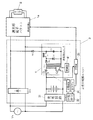
本発明の第1の実施の形態を図1及び図2に示す。まず、図1の回路構成について説明する。商用交流電源Vsには、スイッチSACを介して電子バラスト1の電源入力端子が接続されている。電子バラスト1の電源入力端子には、スイッチSDCを介して非常用コンバータ4の平滑コンデンサC0が接続されている。非常用コンバータ4の電源入力はスイッチS1を介して二次電池Bに接続されている。これらのスイッチSAC、SDC、S1は例えばリレー接点などで構成することができる。
【0015】
非常用電源ユニット3は、非常用コンバータ4のほかに、その動作電源となる二次電池Bと、その充電回路31、停電検知回路32、切替制御回路33を備えている。充電回路31は商用交流電源Vsに接続されており、商用交流電源Vsを降圧・整流して二次電池Bを充電する。停電検知回路32は充電回路31に接続された商用交流電源Vsの通電状態を監視しており、商用交流電源Vsの停電・復電を検知する。切替制御回路33は停電検知回路32の停電検知信号を受けて、スイッチSAC、S1、SDCを非常時の接続状態に切り替えると共に、制御部41の動作を開始させる。また、停電検知回路32の復電検知信号を受けて、スイッチSAC、S1、SDCを常用時の接続状態に切り替えると共に、制御部41の動作を停止させる。
【0016】
非常用コンバータ4は、発振トランスOTと、その1次巻線と直列接続されたスイッチング素子Qと、スイッチング素子Qを高周波でオン・オフ動作させる制御部41と、発振トランスOTの2次巻線に接続された整流用のダイオードD1と平滑用のインダクタL1と平滑コンデンサC0の直列回路と、インダクタL1と平滑コンデンサC0の直列回路に並列接続された回生電流通電用のダイオードD2とから構成されている。発振トランスOTの1次巻線と2次巻線の巻数比は二次電池Bの直流低電圧を商用電源Vsと同等の電圧レベルに変換できるように設定されている。スイッチS1がオンされた状態で、制御部41の出力によりスイッチング素子Qが高周波でオン・オフ駆動されると、二次電池Bから発振トランスOTの1次巻線に高周波で断続される電流が流れる。これにより、発振トランスOTの2次巻線には巻数比に応じて昇圧された高周波の電圧が発生する。この高周波の電圧がダイオードD1に対して順極性となる期間では、半波整流用のダイオードD1がオンとなり、インダクタL1を介して平滑コンデンサC0が充電される。また、発振トランスOTの2次巻線の電圧がダイオードD1に対して逆極性となる期間では、半波整流用のダイオードD1がオフとなり、インダクタL1の蓄積エネルギーにより、回生電流通電用のダイオードD2がオンとなり、平滑コンデンサC0が充電される。スイッチSDCがオン状態で、スイッチSACがオフ状態であると、平滑コンデンサC0の電圧は電子バラスト1の電源入力端子に供給される。
【0017】
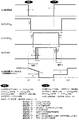
図2において、(a)は商用電源Vsが停電、復電するタイミングを表したもので、(b)〜(d)は図1の各スイッチSAC,SDC,S1のON−OFFタイミングを示している。何れもHighがON、LowがOFF状態を表す。なお図2(e)は、商用電源VsのOFF時及びON時の電子バラスト動作を模式的に表したものであり、非常用電源は供給されない場合、つまり、商用電源のみで動作する場合を前提に示している。
【0018】
停電発生時は、以下のシーケンスにて各スイッチを切り替えて非常用コンバータを起動させる。商用電源電圧が例えば図2(a)のV1以下に低下すると停電を検知(t0)し、スイッチSACをOFFさせる(t1)。次に、スイッチSDCをONする(t2)。さらに、スイッチS1をONして非常用コンバータを起動させる(t3)。そして、非常用コンバータの出力を徐々に増加し定常状態へ移行させる(t4)。t0〜t1はスイッチSACの動作時間A、t1〜t2はスイッチSDCの動作時間B、t2〜t3はスイッチS1の動作時間C、t3〜t4は非常用コンバータの出力立ち上がり時間Dである。
【0019】
ここで、電子バラストは停電(電源OFF)でも即時に動作を停止するものではなく、内蔵の電解コンデンサの残留電荷によってしばらくの間は動作を継続した後、タイマー機能や検出保護機能等がリセットされて初期状態へ戻る。図2(e)のt0〜t5は電子バラストのリセット時間Hである。一方、復電(電源ON)すると、蛍光灯のような熱陰極フィラメントを有するランプを負荷とする電子バラストにおいては、通常、ランプを始動させる前に一定時間の予熱を与えて始動電圧を下げるとともにランプヘのストレス軽減を行なう。図2(e)のt6〜t10は先行予熱時間I(通常約1秒)である。
【0020】
従って、停電の間、非常用電源ユニットにて電子バラストに非常用電源を供給する場合、前述した各スイッチの切り替え及び非常用コンバータの起動時間の合計が上記電子バラストのリセット時間Hを超えると、常用点灯と非常点灯の間に約1秒の予熱期間が介在することになって、非常用照明装置に期待される即時点灯機能を損ねることになる。この観点から、停電時において各スイッチの切り替え及び非常用コンバータの起動を上述のシーケンスにて行なうとともに、それらに要する時間(スイッチSACの動作時間A+スイッチSDCの動作時間B+スイッチS1の動作時間C+出力の立ち上がり時間D)を電子バラストのリセット時間H未満に設定する。
【0021】
同様に、復電時においては、以下のシーケンスにて各スイッチを切り替え、非常用コンバータを停止させる。商用電源電圧が、例えば図2(a)のV2以上に上昇すると復電を検知(t6)し、スイッチS1をOFFして非常用コンバータの動作を停止する(t7)。非常用コンバータの出力平滑用コンデンサC0の残留電荷が減少して、電子バラストへの電源供給が停止した後、スイッチSDCをOFFする(t8)。次に、スイッチSACをONする(t9)。t6〜t7はスイッチS1の動作時間Eである。t7〜t8は電解コンデンサC0の残留電荷放電時間Fであり、スイッチSDCの動作時間となる。また、t8〜t9はスイッチSACの動作時間Gである。
【0022】
停電時と同様、復電時においても各スイッチの切り替え及び非常用コンバータの停止を上述のシーケンスにて行なうとともに、それらに要する時間(スイッチS1の動作時間E+電解コンデンサC0残留電荷放電時間(スイッチSDC動作時間)F+スイッチSACの動作時間G)を電子バラストのリセット時間H未満に設定する。
【0023】
なお本発明においては、非常用電源ユニットの各種切り替え及び制御条件が電子バラストのリセット機能などと密接に関連するため、従来例で示した電源別置型システムとして構成するよりも、器具内蔵型システムとして構成するのに適している。その際、二次電池のセル数の最適化が重要な要素となる。すなわち電池のセル数を増やせば非常用コンバータの昇圧比が小さいので、少ない回路損失設計ができる反面、電池の容積が増えて器具の大型化、コストアップの課題が生じる。また電池のセル数を少なくすれば非常用コンバータの昇圧比を大きく設計する必要があり、また電池の放電電流も大きくなるので回路損失が大きくなり、電池の性能(許容放電電流)によって限界を有する。これらを勘案して目安を掲げれば、最小セル数≧(電子バラスト最大負荷×非常用電源動作時間)/(非常用コンバータ回路効率×電池容量×公称電池電圧)となる。また、最大セル数<電子バラストの最小許容入力電圧/(公称電池電圧×非常用コンバータの昇圧比)となる。ここで、最小セル数時の非常用コンバータの回路効率は、電池の放電電流増大による損失を考慮しても0.6以上の能力が目安となる。また、非常用コンバータの昇圧比は、電池の放電時に1.5〜0.5V/セル程度の電圧変動(ニカド電池の場合)があっても昇圧回路の出力電圧を一定化させるために、3倍以上の能力が目安となる。
【0024】
(第2の実施の形態)
本発明の第2の実施の形態を図4、図5に基づいて説明する。図4の回路は、図1におけるスイッチSACをダイオードブリッジDB1に置き換えると共に、スイッチSDCをダイオードD3に置き換えて無接点化を図ったものである。図4の回路では、図1の回路に比べると、スイッチSACが無いが、代わりにダイオードブリッジDB1が有るので、商用交流電源Vsが停電している場合において非常用コンバータ4が動作しているときには、ダイオードD3を介して電子バラスト1の電源入力部に直流電圧が供給されて、ダイオードブリッジDB1が電圧阻止状態となり、実質的にスイッチSACの機能を果たしている。また、図4の回路では、図1の回路に比べると、スイッチSDCが無いが、代わりにダイオードD3が有るので、商用交流電源Vsが通電している場合において非常用コンバータ4の平滑コンデンサC0の電荷が放電された後はダイオードD3が電圧阻止状態となり、実質的にスイッチSDCの機能を果たしている。その他の構成は図1と同一のため、説明は省略する。
【0025】
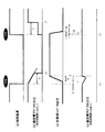
図5は、図4の構成における非常用コンバータの起動、出力立ち上がり条件を示している。図5(a)は商用電源の停電(t0)と復電(t4)のタイミングを示している。図5(b)は、停電中に非常用電源が供給されない場合について、商用電源のOFF時及びON時の電子バラスト動作を模式的に表している。前述のように、商用電源のOFF時(停電時)に電子バラストの諸機能がリセットされる時間(t0〜t3:電子バラストのリセット時間H)が存在し、また、電源ON時(復電時)には約1秒の先行予熱を行なう。t4〜t7は先行予熱時間I(通常約1秒)である。
【0026】
図5(c)は非常用コンバータの動作を模式的に表したもので、t0で停電を検知した後、スイッチS1をONさせる。t0〜t1はスイッチS1の動作時間Cである。その後、非常用コンバータの出力が所定値に上昇する。t1〜t2は非常用コンバータの出力立ち上がり時間Dである。なお、この出力立ち上がり時間を適度に設定すれば、非常用コンバータを構成する電子部品に過渡的に発生する電気的ストレスを軽減するとともに、その出力に発生するオーバーシュートを抑制して電子バラストを保護するのに有効である。また、非常用コンバータの制御回路にソフトスタート回路を付加すれば、出力立ち上がり時間Dの設計が容易となる。また復電時は、t4で復電を検知した後、スイッチS1をOFFさせる。t4〜t5はスイッチS1の動作時間Eである。スイッチS1をOFFして非常時コンバータを停止させれば、平滑コンデンサC0の残留電荷が放出される。t5〜t6は平滑コンデンサC0の残留電荷放電時間Fである。
【0027】
図5(d)は、停電中に非常用電源が供給される場合について、商用の電子バラストの動作を模式的に表したものである。第1の実施の形態では有接点であったスイッチSACおよびSDCをここでは無接点化することにより、上記スイッチS1の動作時間C及び非常用コンバータのソフトスタート時間Dの間は出力が一旦低下するが、これらの合計時間が電子バラストのリセット時間H以下であれば、電子バラストは先行予熱モードに入ることがなく、速やかに非常点灯に移行できる。また復電時は、スイッチS1をOFFして非常用コンバータを停止させれば、平滑コンデンサC0の残留電荷が放出されるが、この場合すでに復電されているので、電子バラストの入力電圧は途切れることなく連続して印加される。なお、上記のスイッチS1は半導体スイッチでもよく、また非常用コンバータ4の制御部41でコンバータの動作をON−OFFさせても構わない。
【0028】
この実施の形態によれば、電子バラストの商用電源側に整流ブリッジを、また非常用電源ユニットから電子バラストへ向けてダイオードD3を設け、更に停電時のスイッチS1の動作時間Cと非常用コンバータの出力立ち上がり時間Dの合計を電子バラストのリセット時間Hより短く設定することによって、高信頼性の非常用照明装置を実現できる。また、この実施の形態においては、非常用電源ユニットの各種切り替え及び制御条件が電子バラストのリセット機能などと密接に関連するため、従来例で示した電源別置型システムとして構成するよりも、器具内蔵型システムとして構成するのに適している。
【0029】
(実施例2−1)
図6の実施例は、図4の基本回路において、電池電圧(非常用コンバータ4の入力電圧)を検出して非常用コンバータ4の制御部41を介して動作を制御するフィードフォワード回路42と、非常用コンバータ4の出力電圧を検出して非常用コンバータ4の制御部41を介して動作を制御するフィードバック回路43を付加したものである。フィードフォワード回路42は、電池電圧が放電開始直後の高い状態では非常用コンバータ4が過負荷動作に至らないように、また、放電末期に電池電圧が所定値以下になった場合には電池の過放電を防止するために非常用コンバータ4の動作を停止させるように動作する。フィードバック回路43は、電子バラスト1側の負荷変動(無負荷や動作停止、始動時など)があっても非常用コンバータ4の出力電圧を所定値に保つように動作する。
【0030】
この実施例のように、フィードフォワード機能やフィードバック機能を付加することによって、電池エネルギーの有効利用と過放電防止、非常用コンバータの過負荷抑制、非常時の電子バラストへの過電圧等によるストレス低減等の効果により、信頼性に優れたシステムを実現できる。なお、フィードフォワード回路やフィードバック回路は、そのどちらか一方のみ付加しても上述の様な効果を得ることができるが、双方を具備することで、より高い信頼性を得ることが可能となる。
【0031】
(第3の実施の形態)
本発明の第3の実施の形態によれば、調光機能を有する非常用照明装置について、非常時に光出力を所定値に設定することを特徴とするものである。
(実施例3−1)
図7の実施例は、調光信号を受けてランプ2を調光点灯させる調光形電子バラスト1aを用い、また非常用電源ユニット3内部に、停電を検知したときに上記調光用電子バラスト1aに調光信号を与えるための調光信号回路34を設けて構成される。非常時に要求される光出力は常用時に比べて低く設定される場合が多く、非常時に調光信号も同時に発生させることによって非常時に所定の光出力を得ることができる。
【0032】
(実施例3−2)
図8の実施例は、調光信号回路34からの調光信号を、二次電池Bの電圧で変調する変調器35を有している。放電の過程で低下していく電池電圧に応じて調光信号回路34からの調光信号に変調を加えて調光形電子バラスト1aに供給することによって、非常時の光出力をある程度一定に保つことができ、電池エネルギーの有効活用が図れる。
【0033】
(実施例3−3)
図9の実施例は、調光形電子バラスト1aと調光器5によって常時調光を行なう場合の例である。非常時は停電を検知して調光信号を発生するとともに、この信号と調光器5を切り替えるスイッチS2によって構成される。スイッチS2により調光用電子バラスト1aの調光信号端子は、常時は調光器5からの任意の信号を、非常時は非常用電源ユニット3からの予め設定された調光信号を受けることができる。
【0034】
(実施例3−4)
図10の実施例は、停電検知信号を調光器5へ入力し、調光器5内部で常時と非常時の調光信号を発生させる例である。この例の揚含、調光器5は非常時の調光状態を記憶しておく何らかの手段を備えておく必要があるが、図9では常時用と非常時用で別個に備えていた調光信号発生部34を共通化できるため、非常用電源ユニット3の小型化を図ることが出来る。
【0035】
(実施例3−5)
図11の実施例は、電子バラスト1を昇圧チョッパー回路12とその出力に接続されるインバータ回路13で構成し、これらの動作条件をスイッチS21,S22で切り替えるように構成したものである。電子バラスト1の電源入力端子には、雑防回路11を介してダイオードブリッジDB2の交流入力端子が接続されている。雑防回路11とは雑音防止用のフィルター回路であり、電子バラスト1のスイッチング動作による高周波雑音が商用交流電源Vsに漏洩することを防止するための回路である。ダイオードブリッジDB2の直流出力端子(整流出力側)にはインダクタL2とスイッチング素子Q3の直列回路が接続されており、スイッチング素子Q3の両端にはダイオードD4を介して平滑コンデンサC2が接続されている。スイッチング素子Q3は制御回路18により高周波でオン・オフされる。スイッチング素子Q3とインダクタL2、ダイオードD4、平滑コンデンサC2は昇圧チョッパー回路12を構成しており、スイッチング素子Q3のオン・オフ動作により商用交流電源Vsの整流出力を昇圧した直流電圧を平滑コンデンサC2の両端に出力する。平滑コンデンサC2の両端に得られる直流電圧の大きさは、制御回路18によりスイッチング素子Q3のオン期間等を制御することにより可変とすることができる。平滑コンデンサC2の両端にはインバータ回路13が接続されている。インバータ回路13は平滑コンデンサC2の直流電圧をスイッチング素子により高周波電圧に変換してランプ2に供給する。インバータ回路13のスイッチング素子の周波数あるいはオン期間は制御回路14により制御される。
【0036】
停電を検知して光出力の切り替え制御を行なう際に、電子バラスト内部の昇圧チョッパー回路12の制御回路18或いはインバータ回路13の制御回路14の動作条件をスイッチS21,S22で切り替える。このように、非常時にのみ電子バラスト1を構成する各部の動作条件を変えることによって、外部の調光器等を使用すること無く、非常時の光出力を設定することができる。
【0037】
(実施例3−6)
図12の実施例は、非常用電源ユニット3からの直流出力を電子バラスト1内部のインバータ回路13の入力部に供給するように構成し、非常時に所定の光出力が得られるように非常用電源ユニット3からの直流電圧を設定する。この様な構成によって、電子バラスト1と商用電源Vs間に設けていたダイオードブリッジ(例えば図11のDB1)は不要となり、更に非常時は電子バラスト1内部の昇圧チョッパー回路12は動作しないので、非常時の回路損失が低減されて電池容量の節約も可能となる。
【0038】
この実施の形態によれば、簡単な構成で非常時の光出力を所定値に設定することが可能であり、また電池電圧に応じて調光信号に変調を加えれば非常時の光出力をある程度一定に保つことも可能であり、更に非常用電源ユニットからの直流出力を電子バラスト内部のインバータ回路入力に供給すれば回路構成の簡素化、回路損失の低減が可能となり、小形で経済性に優れた高信頼性のシステムが構成できる。また、非常時の光出力は、調光信号発生部の部品を変更することで容易に設定可能であるが、例えばディップスイッチやボリューム等を使用すれば、ユニット外部から容易に設定を変更することも可能となり、汎用性をより一層高めることも可能となる。
なお、電子バラスト、放電灯、二次電池、常用調光器を除いて一つのプリント基板上に実装し、かつ常用調光器を除いた全てを一つの照明器具に内蔵することが好ましい。
【0039】
(第4の実施の形態)
本発明の第4の実施の形態によれば、電子バラストに付加された検出保護機能を、非常時においては除去あるいは感度低減して非常点灯を最優先させることによって、安全性確保に適した非常用照明を実現できる。
この実施の形態を図13に基づいて説明する。昇圧回路12は上述の昇圧チョッパー回路などで構成されており、平滑コンデンサC2の両端に直流電圧を得ている。インバータ回路13の電源入力部では、平滑コンデンサC2の両端にスイッチング素子Q1,Q2の直列回路を接続している。これらのスイッチング素子Q1,Q2は制御回路14の出力により高周波で交互にオン・オフされる。一方のスイッチング素子Q2の両端には、直流カット用のコンデンサC4と、共振用のインダクタL3を介して、蛍光ランプ2が接続されている。蛍光ランプ2のフィラメントの非電源側端子間には共振用のコンデンサC3が並列接続されている。コンデンサC3とインダクタL3は共振回路を構成している。ランプ2の両端(端子▲1▼−▲2▼間)には検出回路17が接続されている。この検出回路17は後述するように寿命末期や無負荷等の異常を検出して端子▲3▼に負荷異常検出信号を発生する。この負荷異常検出信号を受けて発振停止保持回路15が端子▲4▼に発振停止保持信号を出力し、制御回路14の動作を停止させる。また、先行予熱タイマー16は電源投入後の一定期間は端子▲5▼に先行予熱期間を示す信号を出力し、インバータ回路13の出力をランプ2が点灯しないレベルに低減させる。
【0040】
電子バラストにおける検出回路17は、主にランプ寿命末期にフィラメントに塗布されたエミッタが消滅することによる異常放電に対して回路及びランプを保護するために設けられるもので、ランプ間の電圧上昇或いは電流増加を検出してインバータ動作を停止・保持させたり、出力を低減・保持あるいは間欠動作させる場合が多い。図13の回路では、非常用電源ユニットの停電検知部で停電を検知して非常点灯のための切り替え制御を行なう際に、図14〜図17の各実施例のように、電子バラスト内部のインバータ回路の一部を同時に操作するように構成している。
【0041】
(実施例4−1)
図14は先行予熱タイマー回路16の回路構成を一例として示している。電子バラスト1の電源が投入されて、制御電源電圧Vccが立ち上がると、抵抗R11を介してツェナーダイオードDz1に電流が流れて、ツェナーダイオードDz1の両端に生じる一定の基準電圧がコンパレータCOMP1の+側入力端子に印加される。また、抵抗R12とコンデンサC11よりなる時定数回路(積分回路)に制御電源電圧Vccが印加され、コンデンサC11の電圧が徐々に上昇する。このコンデンサC11の電圧はコンパレータCOMP1の−側入力端子に印加されて、ツェナーダイオードDz1の基準電圧と比較されている。コンデンサC11の電圧は電源投入後、約1秒後にツェナーダイオードDz1の電圧に達するように抵抗R12とコンデンサC11の値を設定されている。これによりコンパレータCOMP1の出力(端子▲5▼)は電源投入後の約1秒間はHighレベルとなり、その後はLowレベルとなる。端子▲5▼はインバータ回路13の制御回路14に接続されて、電源投入後の一定期間は、インバータ回路13の出力をランプ2が点灯しないレベルに低減させる。これにより、ランプ2のフィラメントを十分に予熱して常用点灯時のランプ寿命を確保している。
【0042】
一方、非常用電源ユニット3の切替制御回路33が動作したときには、スイッチSW1がオンとなり、非常時にコンデンサC11への充電を促進するための抵抗R13を積分回路の抵抗R12に並列接続する。R12≫R13と設定しておくことにより、抵抗R13を介して急速にコンデンサC11が充電されるため、先行予熱タイマーの予熱時間(通常約1秒)を短縮して速やかに光出力を得ることができる。非常用照明装置の使命は、非常時に速やかに必要な光束を確保することにあるので、停電発生とともに先行予熱タイマーの機能を除去或いは時間を短縮することは有効である。
【0043】
(実施例4−2)
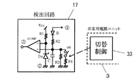
図15は検出回路17の回路構成を一例として示している。この回路では、ランプ2の両端(端子▲1▼−▲2▼間)の電圧をダイオードDで半波整流し、抵抗R2とR3で分圧してコンデンサCにランプ電圧の検出値を生成し、これをコンパレータCOMPの+側入力端子に印加している。コンパレータCOMPの−側入力端子には抵抗R1とツェナーダイオードDzにより生成した基準電圧が印加されている。ランプ2が寿命末期でなく正常に点灯しているときには、コンデンサCの電圧はツェナーダイオードDzの基準電圧よりも低く、コンパレータCOMPの出力(端子▲3▼)はLowレベルに維持されている。ランプ2が接続されていないとき、あるいは寿命末期(エミレス状態)となったときには、コンデンサCの電圧は上昇し、ツェナーダイオードDzの基準電圧を越える。これによりコンパレータCOMPの出力(端子▲3▼)はHighレベルとなり、ランプ2が寿命末期あるいは無負荷状態であることを検出する。
【0044】
スイッチSWは非常用電源ユニット3の切替制御回路33によって停電検知時にONされる。ランプ2が正常な場合においては検出回路17の両端電圧は低く、抵抗R2とR3及びコンデンサCで分圧・平滑された電位は基準電位未満に設定される。ランプ寿命末期にランプ電圧が上昇すると、上記の検出電圧は基準電位を超えてコンパレータCOMPの出力が反転し、その出力が発振停止・保持回路15に入力されてインバータ回路13は発振動作を停止する。非常時に、非常用電源ユニット3で停電を検知し切替制御回路33によりスイッチSWをONすると、抵抗R3と並列に抵抗R4が接続されて抵抗R2との分圧値は低下するので、抵抗R4の値次第で検出回路17の機能を除去或いは感度低減を行なうことができる。
【0045】
(実施例4−3)
図16は発振停止保持回路15の回路構成を一例として示している。この回路では、検出回路17の出力(端子▲3▼)がHighレベルとなる時間が多くなると、抵抗R22,R23、コンデンサC21よりなる蓄積回路を介してSCRのゲート電圧が上昇し、SCRがターンオンする。ひとたびSCRがオンすると、常閉スイッチSW2と抵抗R21を介して制御電源電圧Vccからグランド(端子▲2▼)にSCRの保持電流が流れ続けるので、発振停止保持回路15の出力(端子▲4▼)はLowレベルに保持される。これにより制御回路14は動作を停止し、インバータ回路13の発振停止状態を保持する。
【0046】
この実施例では常用時に検出回路17が動作して発振停止・保持回路15が動作した状態で停電が発生した場合、発振停止・保持機能を解除して非常点灯を行なうことができる。すなわち、非常用電源ユニット3の切替制御回路33が動作して常開スイッチSW2がオフされると、SCRの保持電流が遮断されて、SCRはターンオフする。また、発振停止保持回路15の出力(端子▲4▼)は抵抗R21を介して制御電源電圧Vccに接続されるので、Highレベルとなり、インバータ回路13の発振停止保持は解除される。
【0047】
(実施例4−4)
図17の実施例は図15に示した検出回路17の抵抗R3と並列に負特性サーミスタRtを接続したものであり、特に火災を想定した高温状態(例えば100℃以上:火災時以外は非常に可能性が低く、電子バラストを構成する電子部品の信頼性を損なわない程度の温度)では検出回路17の感度を低下させて、高温でランプ2に異常放電が起こっても検出回路17が動作しないようにして非常点灯を最優先させている。
この実施の形態によれば、電子バラストに付加された検出保護機能を、非常時においては除去あるいは感度低減して非常点灯を最優先させることによって、安全性確保に適した非常用照明を実現できる。
【0048】
【発明の効果】
請求項1の発明によれば、商用電源と電子バラストを接続、切断するためのスイッチ、及び、非常用コンバータと電子バラストを接続、切断するためのスイッチを用いた構成において、停電時及び復電時に各スイッチの切り替え、非常用コンバータの起動・停止を適切な順序で行なうとともに、それらに要する時間が電子バラストのリセット時間未満となるように設定したので、高信頼性を保ちながら速やかに非常点灯に切り替えることができる。すなわち、商用電源でも直流電源でも動作可能な交直両用型の電子バラストを用いた非常用電源ユニットにおいて、停電及び復電の際に切り替えるスイッチのストレスに起因する設備の大型化や経済的な課題を解決することができる。
また、請求項1〜11の発明によれば、電子バラストは、放電灯の寿命末期を検出するための検出回路と、内部温度が約100℃を超える温度に至った場合には上記検出回路の検出感度を低減あるいは検出動作を停止させる手段を有するので、電子バラストに付加された検出保護機能を、非常時においては除去あるいは感度低減して非常点灯を最優先させることができ、安全性確保に適した非常用照明を実現できる。
請求項2の発明によれば、商用電源と電子バラストを接続、切断するためのスイッチを整流ブリッジに、非常用コンバータと電子バラストを接続、切断するためのスイッチをダイオードに置き換えて無接点化を図った構成において、停電時の非常用コンバータ起動時間と出力立ち上がり時間の合計を電子バラストのリセット時間より短く設定することによって、高信頼性の非常用照明装置を実現できる。
請求項3の発明によれば、フィードフォワード機能やフィードバック機能を付加することによって、電池エネルギーの有効利用と過放電防止、非常用コンバータの過負荷抑制、非常時の電子バラストヘの過電圧等によるストレス低減等の効果により、信頼性に優れたシステムを実現できる。
【0049】
請求項4の発明によれば、調光信号を受けてランプを調光点灯させる調光形電子バラストを用い、また非常用電源ユニット内部に、停電を検知したときに上記調光用電子バラストに調光信号を与えるための調光信号回路を設けて構成され、簡単な構成で非常時の光出力を所定値に設定することが可能であり、適切な光出力を得ることにより、経済性及び安全性を一段と向上させることができる。
請求項5の発明によれば、電池電圧に応じて調光信号に変調を加えることで、非常時の光出力をある程度一定に保つことが可能である。
【0050】
請求項8の発明によれば、更に非常用電源ユニットからの直流出力を電子バラスト内部のインバータ回路入力に供給することで、回路構成の簡素化、回路損失の低減が可能となり、小形で経済性に優れた高信頼性のシステムが構成できる。請求項9の発明によれば、電子バラストのインバータ回路部と非常用電源ユニットの切替制御回路を連動させることによって、停電発生時には電子バラストに付加された検出保護機能を除去あるいは感度低減して非常点灯を最優先させることによって、安全性確保に適した非常用照明を実現できるものである。
請求項10の発明によれば、停電発生時には電子バラストによる放電灯のフィラメントの予熱を短縮あるいは省略するようにしたから、非常時に速やかに必要な光束を確保することができ、安全性確保に適した非常用照明を実現できるものである。
【図面の簡単な説明】
【図1】本発明の第1の実施の形態の回路図である。
【図2】本発明の第1の実施の形態の動作説明図である。
【図3】従来例の回路図である。
【図4】本発明の第2の実施の形態の回路図である。
【図5】本発明の第2の実施の形態の動作説明図である。
【図6】本発明の第2の実施の形態の一実施例を示す回路図である。
【図7】本発明の第3の実施の形態の第1実施例を示す回路図である。
【図8】本発明の第3の実施の形態の第2実施例を示す回路図である。
【図9】本発明の第3の実施の形態の第3実施例を示す回路図である。
【図10】本発明の第3の実施の形態の第4実施例の要部構成を示す回路図である。
【図11】本発明の第3の実施の形態の第5実施例を示す回路図である。
【図12】本発明の第3の実施の形態の第6実施例を示す回路図である。
【図13】本発明の第4の実施の形態の回路図である。
【図14】本発明の第4の実施の形態の第1実施例の要部構成を示す回路図である。
【図15】本発明の第4の実施の形態の第2実施例の要部構成を示す回路図である。
【図16】本発明の第4の実施の形態の第3実施例の要部構成を示す回路図である。
【図17】本発明の第4の実施の形態の第4実施例の要部構成を示す回路図である。
【符号の説明】
1 電子バラスト
2 ランプ
31 充電回路
32 停電検知回路
33 切替制御回路
4 非常用コンバータ
Vs 商用電源
SAC 第1のスイッチ
S1 第2のスイッチ
SDC 第3のスイッチ
C0 平滑コンデンサ[0001]
BACKGROUND OF THE INVENTION
The present invention relates to an emergency lighting device, and relates to an emergency power supply for emergency lighting using a regular lighting device as it is even during a power failure.
[0002]
[Prior art]
The basic configuration of the emergency lighting device is shown in FIG. The
[0003]
FIG. 1 shows an example in which a normal
[0004]
Always contact S from commercial power supply VsACThe
[0005]
In the conventional example using the AC / DC
[0006]
In addition, a contactless method using a semiconductor element is generally known for such a problem, and there is no possibility of contact welding, which is advantageous in terms of reliability. Considering electrical stress, an expensive semiconductor element with a large current and a high voltage is required.
[0007]
Including the contact method and non-contact method, the switch element stress can be reduced while providing a sufficient interval at the time of switching. However, when the electronic ballast that lights the discharge lamp is used as a load, the filament is preheated for a certain period of time when the power is turned on. In many cases, a function to perform the emergency lighting operation may be impaired depending on the interval at the time of switching.
[0008]
[Problems to be solved by the invention]
The present invention has been made in view of the above points, and is a switching element that is switched at the time of a power failure and power recovery in an emergency lighting device using an AC / DC type electronic ballast that can operate with either a commercial power supply or a DC power supply. To improve the economic efficiency and safety by solving large-scale equipment and economic problems caused by the stress of the environment, as well as promptly switching to emergency lighting in the event of a power failure and ensuring appropriate light output in the event of an emergency Is an issue.
[0009]
[Means for Solving the Problems]
According to invention of
[0010]
According to the invention of
According to the invention of
[0011]
According to the invention of
According to the invention of
According to the invention of claim 6, as shown in FIG. 9, the
[0012]
According to the invention of claim 7, as shown in FIG. 11, the
According to the invention of
[0013]
According to the invention of claim 9, the
According to the invention of
Hereinafter, embodiments of the present invention will be described. (Example 4-4) corresponds to the present invention, and the rest will be described as a premise configuration.
[0014]
DETAILED DESCRIPTION OF THE INVENTION
(First embodiment)
A first embodiment of the present invention is shown in FIGS. First, the circuit configuration of FIG. 1 will be described. The commercial AC power supply Vs has a switch SACThe power input terminal of the
[0015]
In addition to the
[0016]
The
[0017]
In FIG. 2, (a) shows the timing when the commercial power supply Vs is interrupted and restored, and (b) to (d) show the switches S in FIG.AC, SDC, S1 ON-OFF timing. In either case, High represents ON and Low represents OFF. FIG. 2 (e) schematically shows the electronic ballast operation when the commercial power source Vs is OFF and ON, and it is assumed that the emergency power source is not supplied, that is, operates with only the commercial power source. It shows.
[0018]
When a power failure occurs, switch the switches in the following sequence to start the emergency converter. When the commercial power supply voltage drops below V1 in FIG. 2A, for example, a power failure is detected (t0), and the switch SACIs turned off (t1). Next, switch SDCIs turned on (t2). Further, the switch S1 is turned on to activate the emergency converter (t3). Then, the output of the emergency converter is gradually increased to shift to a steady state (t4). t0 to t1 are switches SACOperating time A, t1 to t2 are switches SDCThe operation time B, t2 to t3 are the operation time C of the switch S1, and t3 to t4 are the output rise time D of the emergency converter.
[0019]
Here, the electronic ballast does not stop operation immediately even if a power failure occurs (the power is turned off). After the operation continues for a while due to the residual charge in the built-in electrolytic capacitor, the timer function, detection protection function, etc. are reset. To return to the initial state. In FIG. 2E, t0 to t5 are the electronic ballast reset time H. On the other hand, when power is restored (power ON), in an electronic ballast that uses a lamp having a hot cathode filament such as a fluorescent lamp as a load, usually a preheating is performed for a certain time before starting the lamp to lower the starting voltage. Reduce the stress on the lamp. T6 to t10 in FIG. 2 (e) is the preceding preheating time I (usually about 1 second).
[0020]
Therefore, when supplying emergency power to the electronic ballast in the emergency power supply unit during a power failure, if the total of the switching time of each switch and the start-up time of the emergency converter exceeds the reset time H of the electronic ballast, The preheating period of about 1 second is interposed between the normal lighting and the emergency lighting, and the immediate lighting function expected for the emergency lighting device is impaired. From this point of view, each switch is switched and the emergency converter is started in the above sequence in the event of a power failure, and the time required for them (switch SACOperating time A + switch SDCThe operation time B + the operation time C of the switch S1 + the output rise time D) is set to be less than the reset time H of the electronic ballast.
[0021]
Similarly, at the time of power recovery, each switch is switched in the following sequence to stop the emergency converter. When the commercial power supply voltage rises to, for example, V2 in FIG. 2A or more, power recovery is detected (t6), the switch S1 is turned off, and the operation of the emergency converter is stopped (t7). After the residual charge of the output smoothing capacitor C0 of the emergency converter is reduced and the power supply to the electronic ballast is stopped, the switch SDCIs turned off (t8). Next, switch SACIs turned on (t9). t6 to t7 is the operation time E of the switch S1. t7 to t8 is the residual charge discharge time F of the electrolytic capacitor C0, and the switch SDCOperating time. T8 to t9 are switches SACOperating time G.
[0022]
As in the case of a power failure, switching of each switch and stopping of the emergency converter are performed in the above-described sequence at the time of power recovery, and the time required for them (operating time E of switch S1 + electrolytic capacitor C0 residual charge discharging time (switch SDCOperating time) F + switch SACIs set to be less than the reset time H of the electronic ballast.
[0023]
In the present invention, the various switching and control conditions of the emergency power supply unit are closely related to the electronic ballast reset function, etc. Suitable for configuring. At that time, the optimization of the number of cells of the secondary battery is an important factor. That is, if the number of cells of the battery is increased, the step-up ratio of the emergency converter is small, so that it is possible to design a small circuit loss. In addition, if the number of battery cells is reduced, it is necessary to increase the step-up ratio of the emergency converter, and the discharge current of the battery also increases, so the circuit loss increases, and there is a limit depending on the battery performance (allowable discharge current). . Taking these into consideration, the minimum cell number ≧ (electronic ballast maximum load × emergency power supply operating time) / (emergency converter circuit efficiency × battery capacity × nominal battery voltage). Further, the maximum number of cells <the minimum allowable input voltage of electronic ballast / (nominal battery voltage × boost ratio of the emergency converter). Here, the circuit efficiency of the emergency converter when the number of cells is the minimum is an ability of 0.6 or more even when the loss due to the increase in the discharge current of the battery is taken into consideration. Further, the boost ratio of the emergency converter is 3 in order to make the output voltage of the booster circuit constant even if there is a voltage fluctuation of about 1.5 to 0.5 V / cell (in the case of a nickel-cadmium battery) during battery discharge. The ability is more than double.
[0024]
(Second Embodiment)
A second embodiment of the present invention will be described with reference to FIGS. The circuit of FIG. 4 includes the switch S in FIG.ACIs replaced with the diode bridge DB1 and the switch SDCIs replaced with a diode D3 to achieve contactlessness. In the circuit of FIG. 4, compared to the circuit of FIG.ACHowever, since there is a diode bridge DB1 instead, a DC voltage is applied to the power input portion of the
[0025]
FIG. 5 shows the start-up and output rise conditions of the emergency converter in the configuration of FIG. FIG. 5A shows the timing of commercial power failure (t0) and power recovery (t4). FIG. 5B schematically shows the electronic ballast operation when the commercial power supply is OFF and when the emergency power supply is not supplied during a power failure. As described above, there is a time (t0 to t3: electronic ballast reset time H) during which various functions of the electronic ballast are reset when the commercial power supply is turned off (power failure), and when the power is turned on (when power is restored). ) Is pre-heated for about 1 second. t4 to t7 is the preceding preheating time I (usually about 1 second).
[0026]
FIG. 5C schematically shows the operation of the emergency converter. After detecting a power failure at t0, the switch S1 is turned on. t0 to t1 is the operation time C of the switch S1. Thereafter, the output of the emergency converter rises to a predetermined value. t1 to t2 are output rise times D of the emergency converter. If this output rise time is set appropriately, the electrical stress that occurs transiently in the electronic components that make up the emergency converter is reduced, and overshoot that occurs in the output is suppressed to protect the electronic ballast. It is effective to do. Further, if a soft start circuit is added to the control circuit of the emergency converter, the design of the output rise time D becomes easy. When power is restored, switch S1 is turned off after power recovery is detected at t4. t4 to t5 is the operation time E of the switch S1. If the emergency converter is stopped by turning off the switch S1, the residual charge of the smoothing capacitor C0 is released. t5 to t6 are the residual charge discharge time F of the smoothing capacitor C0.
[0027]
FIG. 5D schematically illustrates the operation of a commercial electronic ballast when emergency power is supplied during a power failure. Switch S, which was a contact in the first embodimentACAnd SDCIn this case, the output is temporarily reduced during the operation time C of the switch S1 and the soft start time D of the emergency converter. However, the total time is less than the reset time H of the electronic ballast. In this case, the electronic ballast does not enter the preceding preheating mode, and can quickly shift to emergency lighting. At the time of power recovery, if the emergency converter is stopped by turning off the switch S1, the residual charge of the smoothing capacitor C0 is released. In this case, since the power is already recovered, the input voltage of the electronic ballast is interrupted. Without being applied continuously. The switch S1 may be a semiconductor switch, and the
[0028]
According to this embodiment, the rectifier bridge is provided on the commercial power supply side of the electronic ballast, the diode D3 is provided from the emergency power supply unit to the electronic ballast, and the operation time C of the switch S1 in the event of a power failure and the emergency converter By setting the total of the output rise time D to be shorter than the reset time H of the electronic ballast, a highly reliable emergency lighting device can be realized. Also, in this embodiment, various switching and control conditions of the emergency power supply unit are closely related to the electronic ballast reset function, etc. Suitable for configuring as a mold system.
[0029]
(Example 2-1)
The embodiment of FIG. 6 includes a
[0030]
As in this embodiment, by adding a feed forward function and a feedback function, effective use of battery energy and prevention of overdischarge, suppression of overload of an emergency converter, reduction of stress due to overvoltage to an electronic ballast in an emergency, etc. As a result, a highly reliable system can be realized. Even if only one of the feedforward circuit and the feedback circuit is added, the above-described effect can be obtained. However, by providing both, it is possible to obtain higher reliability.
[0031]
(Third embodiment)
According to the third embodiment of the present invention, an emergency lighting device having a dimming function is characterized in that the light output is set to a predetermined value in an emergency.
(Example 3-1)
The embodiment shown in FIG. 7 uses a dimming
[0032]
(Example 3-2)
The embodiment of FIG. 8 has a
[0033]
(Example 3-3)
The embodiment of FIG. 9 is an example in the case where the dimming
[0034]
(Example 3-4)
The embodiment of FIG. 10 is an example in which a power failure detection signal is input to the
[0035]
(Example 3-5)
In the embodiment of FIG. 11, the
[0036]
When a power failure is detected and optical output switching control is performed, the operating conditions of the
[0037]
(Example 3-6)
The embodiment of FIG. 12 is configured to supply the direct current output from the emergency
[0038]
According to this embodiment, the emergency light output can be set to a predetermined value with a simple configuration, and if the light control signal is modulated in accordance with the battery voltage, the emergency light output can be increased to some extent. It can be kept constant, and if the DC output from the emergency power supply unit is supplied to the inverter circuit input inside the electronic ballast, the circuit configuration can be simplified and the circuit loss can be reduced. A highly reliable system can be configured. The emergency light output can be easily set by changing the components of the dimming signal generator. For example, if a dip switch or volume is used, the setting can be easily changed from outside the unit. It becomes possible, and versatility can be further enhanced.
In addition, it is preferable to mount on one printed circuit board except an electronic ballast, a discharge lamp, a secondary battery, and a common dimmer, and to incorporate all except a common dimmer in one lighting fixture.
[0039]
(Fourth embodiment)
According to the fourth embodiment of the present invention, the detection protection function added to the electronic ballast is removed or the sensitivity is reduced in an emergency, and emergency lighting is given the highest priority. Lighting can be realized.
This embodiment will be described with reference to FIG. The
[0040]
The
[0041]
(Example 4-1)
FIG. 14 shows an example of the circuit configuration of the preceding
[0042]
On the other hand, when the switching
[0043]
(Example 4-2)
FIG. 15 shows the circuit configuration of the
[0044]
The switch SW is turned on when a power failure is detected by the switching
[0045]
(Example 4-3)
FIG. 16 shows a circuit configuration of the oscillation stop /
[0046]
In this embodiment, when a power failure occurs with the
[0047]
(Example 4-4)
The embodiment of FIG. 17 is obtained by connecting a negative characteristic thermistor Rt in parallel with the resistor R3 of the
According to this embodiment, the emergency protection lighting suitable for ensuring safety can be realized by removing or reducing the sensitivity of the detection protection function added to the electronic ballast and giving priority to emergency lighting. .
[0048]
【The invention's effect】
According to the first aspect of the present invention, in the configuration using the switch for connecting and disconnecting the commercial power source and the electronic ballast, and the switch for connecting and disconnecting the emergency converter and the electronic ballast, Sometimes the switches are switched and the emergency converter is started and stopped in the proper order, and the time required for them is set to be less than the reset time of the electronic ballast, so that the emergency lighting can be performed quickly while maintaining high reliability. You can switch to In other words, in an emergency power supply unit using an AC / DC type electronic ballast that can be operated with either a commercial power supply or a DC power supply, there is an increase in equipment size and economic issues due to the stress of the switch that is switched during a power failure and power recovery. Can be solved.
According to the invention of
According to the second aspect of the present invention, the switch for connecting and disconnecting the commercial power supply and the electronic ballast is replaced with a rectifier bridge, and the switch for connecting and disconnecting the emergency converter and the electronic ballast is replaced with a diode so that no contact is made. In the configuration shown, a highly reliable emergency lighting device can be realized by setting the sum of the emergency converter start-up time and the output rise time during a power failure to be shorter than the reset time of the electronic ballast.
According to the invention of
[0049]
According to the invention of
According to the fifth aspect of the present invention, the light output in an emergency can be kept constant to some extent by modulating the dimming signal according to the battery voltage.
[0050]
According to the invention of
According to the invention of
[Brief description of the drawings]
FIG. 1 is a circuit diagram of a first embodiment of the present invention.
FIG. 2 is an operation explanatory diagram of the first embodiment of the present invention.
FIG. 3 is a circuit diagram of a conventional example.
FIG. 4 is a circuit diagram of a second embodiment of the present invention.
FIG. 5 is an operation explanatory diagram of a second embodiment of the present invention.
FIG. 6 is a circuit diagram showing an example of the second embodiment of the present invention.
FIG. 7 is a circuit diagram showing a first example of the third embodiment of the present invention;
FIG. 8 is a circuit diagram showing a second example of the third embodiment of the present invention;
FIG. 9 is a circuit diagram showing a third example of the third embodiment of the present invention;
FIG. 10 is a circuit diagram showing a main configuration of a fourth example of the third embodiment of the present invention;
FIG. 11 is a circuit diagram showing a fifth example of the third embodiment of the present invention;
FIG. 12 is a circuit diagram showing a sixth example of the third embodiment of the present invention;
FIG. 13 is a circuit diagram of a fourth embodiment of the present invention.
FIG. 14 is a circuit diagram showing a main configuration of a first example of the fourth embodiment of the present invention;
FIG. 15 is a circuit diagram showing a main configuration of a second example of the fourth embodiment of the present invention;
FIG. 16 is a circuit diagram showing the main configuration of a third example of the fourth embodiment of the present invention;
FIG. 17 is a circuit diagram showing a main configuration of a fourth example of the fourth embodiment of the present invention;
[Explanation of symbols]
1 Electronic ballast
2 lamps
31 Charging circuit
32 Power failure detection circuit
33 Switching control circuit
4 Emergency converter
Vs Commercial power supply
SAC First switch
S1 Second switch
SDC Third switch
C0 smoothing capacitor
Claims (11)
Priority Applications (1)
| Application Number | Priority Date | Filing Date | Title |
|---|---|---|---|
| JP2001366635A JP4131102B2 (en) | 2001-11-30 | 2001-11-30 | Emergency lighting system |
Applications Claiming Priority (1)
| Application Number | Priority Date | Filing Date | Title |
|---|---|---|---|
| JP2001366635A JP4131102B2 (en) | 2001-11-30 | 2001-11-30 | Emergency lighting system |
Publications (2)
| Publication Number | Publication Date |
|---|---|
| JP2003168578A JP2003168578A (en) | 2003-06-13 |
| JP4131102B2 true JP4131102B2 (en) | 2008-08-13 |
Family
ID=19176504
Family Applications (1)
| Application Number | Title | Priority Date | Filing Date |
|---|---|---|---|
| JP2001366635A Expired - Fee Related JP4131102B2 (en) | 2001-11-30 | 2001-11-30 | Emergency lighting system |
Country Status (1)
| Country | Link |
|---|---|
| JP (1) | JP4131102B2 (en) |
Families Citing this family (5)
| Publication number | Priority date | Publication date | Assignee | Title |
|---|---|---|---|---|
| JP4765486B2 (en) * | 2005-08-26 | 2011-09-07 | パナソニック電工株式会社 | Lighting device, lighting fixture |
| KR101050202B1 (en) | 2009-04-30 | 2011-07-19 | (주)이피에스코리아 | Emergency lighting control circuit and its control method |
| JP5883358B2 (en) * | 2012-07-12 | 2016-03-15 | 京セラ株式会社 | Power conditioner system, power supply switching device, and power supply switching method |
| JP6188303B2 (en) * | 2012-10-17 | 2017-08-30 | 三菱電機株式会社 | Lighting device |
| JP6395127B2 (en) * | 2014-04-30 | 2018-09-26 | 岩崎電気株式会社 | Lighting equipment |
-
2001
- 2001-11-30 JP JP2001366635A patent/JP4131102B2/en not_active Expired - Fee Related
Also Published As
| Publication number | Publication date |
|---|---|
| JP2003168578A (en) | 2003-06-13 |
Similar Documents
| Publication | Publication Date | Title |
|---|---|---|
| US6784624B2 (en) | Electronic ballast system having emergency lighting provisions | |
| US4751398A (en) | Lighting system for normal and emergency operation of high intensity discharge lamps | |
| JP4944562B2 (en) | Switching power supply | |
| US4864482A (en) | Conversion circuit for limiting inrush current | |
| EP2298030A2 (en) | Led lamp driver and method | |
| WO1998028671A1 (en) | Power supply and electronic ballast with low-cost inverter bootstrap power source | |
| JP2008104273A (en) | Phase-controllable dc constant current power supply | |
| KR101676869B1 (en) | False failure prevention circuit in emergency ballast | |
| JP4748025B2 (en) | Phase control power supply | |
| JP5210419B2 (en) | Switching power supply device and lighting apparatus using the same | |
| JP2008104275A (en) | Constant current controlled dc-dc converter circuit with function for interrupting no-load oscillation | |
| JP5324817B2 (en) | LED drive device, vehicle lighting device | |
| JP4131102B2 (en) | Emergency lighting system | |
| EP1507327A1 (en) | Emergency lighting unit with integrated electronic ballast | |
| JP2015088344A (en) | Backup power supply for power failure lamp, and power failure lamp unit | |
| JP3521687B2 (en) | Discharge lamp lighting device | |
| KR100831739B1 (en) | Lighting control device of illuminator in both common use and emergency | |
| JP7476642B2 (en) | Emergency devices, lighting equipment | |
| JP2013246938A (en) | Illuminating device, and illuminating fixture | |
| JP4088911B2 (en) | Discharge lamp lighting device | |
| JP2818595B2 (en) | Discharge lamp lighting device | |
| JP3829342B2 (en) | Discharge lamp lighting device | |
| GB2269062A (en) | Emergency lighting; Battery charging | |
| JP2008187759A (en) | Switching power supply circuit | |
| JPH0458493A (en) | Lighting device |
Legal Events
| Date | Code | Title | Description |
|---|---|---|---|
| A621 | Written request for application examination |
Free format text: JAPANESE INTERMEDIATE CODE: A621 Effective date: 20040826 |
|
| A977 | Report on retrieval |
Free format text: JAPANESE INTERMEDIATE CODE: A971007 Effective date: 20071005 |
|
| A131 | Notification of reasons for refusal |
Free format text: JAPANESE INTERMEDIATE CODE: A131 Effective date: 20071016 |
|
| A521 | Written amendment |
Free format text: JAPANESE INTERMEDIATE CODE: A523 Effective date: 20071214 |
|
| A131 | Notification of reasons for refusal |
Free format text: JAPANESE INTERMEDIATE CODE: A131 Effective date: 20080205 |
|
| A521 | Written amendment |
Free format text: JAPANESE INTERMEDIATE CODE: A523 Effective date: 20080404 |
|
| TRDD | Decision of grant or rejection written | ||
| A01 | Written decision to grant a patent or to grant a registration (utility model) |
Free format text: JAPANESE INTERMEDIATE CODE: A01 Effective date: 20080430 |
|
| A01 | Written decision to grant a patent or to grant a registration (utility model) |
Free format text: JAPANESE INTERMEDIATE CODE: A01 |
|
| A61 | First payment of annual fees (during grant procedure) |
Free format text: JAPANESE INTERMEDIATE CODE: A61 Effective date: 20080513 |
|
| FPAY | Renewal fee payment (event date is renewal date of database) |
Free format text: PAYMENT UNTIL: 20110606 Year of fee payment: 3 |
|
| R150 | Certificate of patent or registration of utility model |
Free format text: JAPANESE INTERMEDIATE CODE: R150 |
|
| S533 | Written request for registration of change of name |
Free format text: JAPANESE INTERMEDIATE CODE: R313533 |
|
| FPAY | Renewal fee payment (event date is renewal date of database) |
Free format text: PAYMENT UNTIL: 20110606 Year of fee payment: 3 |
|
| R350 | Written notification of registration of transfer |
Free format text: JAPANESE INTERMEDIATE CODE: R350 |
|
| FPAY | Renewal fee payment (event date is renewal date of database) |
Free format text: PAYMENT UNTIL: 20120606 Year of fee payment: 4 |
|
| FPAY | Renewal fee payment (event date is renewal date of database) |
Free format text: PAYMENT UNTIL: 20120606 Year of fee payment: 4 |
|
| FPAY | Renewal fee payment (event date is renewal date of database) |
Free format text: PAYMENT UNTIL: 20130606 Year of fee payment: 5 |
|
| LAPS | Cancellation because of no payment of annual fees |