JP4131099B2 - Double row radial ball bearing - Google Patents
Double row radial ball bearing Download PDFInfo
- Publication number
- JP4131099B2 JP4131099B2 JP2001327293A JP2001327293A JP4131099B2 JP 4131099 B2 JP4131099 B2 JP 4131099B2 JP 2001327293 A JP2001327293 A JP 2001327293A JP 2001327293 A JP2001327293 A JP 2001327293A JP 4131099 B2 JP4131099 B2 JP 4131099B2
- Authority
- JP
- Japan
- Prior art keywords
- outer ring
- raceway
- inner ring
- ball bearing
- double
- Prior art date
- Legal status (The legal status is an assumption and is not a legal conclusion. Google has not performed a legal analysis and makes no representation as to the accuracy of the status listed.)
- Expired - Fee Related
Links
Images


Classifications
-
- F—MECHANICAL ENGINEERING; LIGHTING; HEATING; WEAPONS; BLASTING
- F16—ENGINEERING ELEMENTS AND UNITS; GENERAL MEASURES FOR PRODUCING AND MAINTAINING EFFECTIVE FUNCTIONING OF MACHINES OR INSTALLATIONS; THERMAL INSULATION IN GENERAL
- F16C—SHAFTS; FLEXIBLE SHAFTS; ELEMENTS OR CRANKSHAFT MECHANISMS; ROTARY BODIES OTHER THAN GEARING ELEMENTS; BEARINGS
- F16C19/00—Bearings with rolling contact, for exclusively rotary movement
- F16C19/02—Bearings with rolling contact, for exclusively rotary movement with bearing balls essentially of the same size in one or more circular rows
- F16C19/14—Bearings with rolling contact, for exclusively rotary movement with bearing balls essentially of the same size in one or more circular rows for both radial and axial load
- F16C19/18—Bearings with rolling contact, for exclusively rotary movement with bearing balls essentially of the same size in one or more circular rows for both radial and axial load with two or more rows of balls
- F16C19/181—Bearings with rolling contact, for exclusively rotary movement with bearing balls essentially of the same size in one or more circular rows for both radial and axial load with two or more rows of balls with angular contact
- F16C19/183—Bearings with rolling contact, for exclusively rotary movement with bearing balls essentially of the same size in one or more circular rows for both radial and axial load with two or more rows of balls with angular contact with two rows at opposite angles
- F16C19/184—Bearings with rolling contact, for exclusively rotary movement with bearing balls essentially of the same size in one or more circular rows for both radial and axial load with two or more rows of balls with angular contact with two rows at opposite angles in O-arrangement
-
- F—MECHANICAL ENGINEERING; LIGHTING; HEATING; WEAPONS; BLASTING
- F16—ENGINEERING ELEMENTS AND UNITS; GENERAL MEASURES FOR PRODUCING AND MAINTAINING EFFECTIVE FUNCTIONING OF MACHINES OR INSTALLATIONS; THERMAL INSULATION IN GENERAL
- F16C—SHAFTS; FLEXIBLE SHAFTS; ELEMENTS OR CRANKSHAFT MECHANISMS; ROTARY BODIES OTHER THAN GEARING ELEMENTS; BEARINGS
- F16C33/00—Parts of bearings; Special methods for making bearings or parts thereof
- F16C33/30—Parts of ball or roller bearings
- F16C33/58—Raceways; Race rings
- F16C33/583—Details of specific parts of races
- F16C33/585—Details of specific parts of races of raceways, e.g. ribs to guide the rollers
Landscapes
- Engineering & Computer Science (AREA)
- General Engineering & Computer Science (AREA)
- Mechanical Engineering (AREA)
- Rolling Contact Bearings (AREA)
Description
【0001】
【発明の属する技術分野】
本発明は、自動車の車輪を懸架装置に対して回転自在に支持する為の複列ラジアル玉軸受の改良に関する。特に、本発明の複列ラジアル玉軸受は、運転中に、荷重や軸の傾斜、振動が加わる様な条件で使用する場合でも、十分な耐久性確保を図るものである。
【0002】
【従来の技術】
自動車の車輪を懸架装置に対して回転自在に支持する為に、例えば、図1に示す様な複列ラジアル玉軸受1を使用する。この複列ラジアル玉軸受1は、内周面にアンギュラ型の外輪軌道2、2を複列に形成した外輪3と、それぞれが外周面にアンギュラ型の内輪軌道4を形成した1対の内輪5、5と、上記各外輪軌道2、2とこれら各内輪軌道4、4との間にそれぞれ複数個ずつ、保持器9、9により保持した状態で転動自在に設けられた玉6、6とを備える。そして、図示の様に、上記各内輪5、5の軸方向端面同士を互いに突き合わせた状態で、上記各玉6、6に、図1に鎖線γで示す方向の接触角αを付与している。この様に構成する複列ラジアル玉軸受1により、自動車の車輪を懸架装置に対して回転自在に支持する場合には、例えば、上記外輪3を懸架装置を構成するナックルに内嵌固定すると共に、上記各内輪5、5を車輪と共に回転するハブに外嵌固定する。尚、この場合、上記外輪3が使用時にも回転しない固定輪となり、上記各内輪5、5が使用時に回転する回転輪となる。
【0003】
ところで、自動車の運転時に上述の様な複列ラジアル玉軸受1には、ラジアル荷重の他、大きなスラスト荷重やモーメント荷重が負荷される場合がある。一方、この様な場合に、上記複列ラジアル玉軸受1の各構成部材が弾性変形する等により、上記各玉6、6の転動面が上記各軌道2、4の幅方向端縁(これら各軌道2、4の幅方向片側に存在する肩部7、8側の端縁)に乗り上げる可能性がある。そして、この様な乗り上げが生じると、上記各玉6、6の転動面とこれら各軌道2、4との接触部に存在する接触楕円の一部が当該軌道2、4から外れ、エッジロードに基づき、上記各玉6、6の転動面と上記各軌道2、4との接触部の面圧が上昇する。尚、これら各玉6、6の転動面とこれら各軌道2、4との接触部が当該軌道2、4の幅方向端縁にまで達すると、接触部分の形状は楕円ではなくなる(楕円の一部が欠けた形状になる)。但し、本明細書では、説明の便宜上、接触楕円の一部が軌道から外れた場合でも「接触楕円」の語を用いる。
【0004】
又、上述した様なエッジロードに基づく面圧上昇は、上記接触楕円の一部が当該軌道2、4から外れる割合(=当該一部の面積/当該一部を含む接触楕円全体の面積。以下、「玉の乗り上げ率」と言う。)が大きくなる程、大きくなる。この様な面圧上昇は、上記複列ラジアル玉軸受1の転がり疲れ寿命を低下させる原因となる為、実際の設計を行なう場合には、運転時の負荷荷重条件を考慮して、運転時に上記外輪3と上記各内輪5、5とに就いての上記各玉6、6の乗り上げ率がそれぞれ大きくなり過ぎない様に(例えば数%程度に抑えられる様に)している。又、上記外輪3と上記各内輪5、5とで、運転時の上記各玉6、6の乗り上げ率が互いにほぼ等しくなる様にしている。
【0005】
【発明が解決しようとする課題】
上述した様な複列ラジアル玉軸受1の場合、例えば自動車のタイヤが縁石等に勢い良く乗り上げた際に、上記各玉6、6の乗り上げ率が、設計上予定していた値よりも大きくなる可能性がある。そして、この事が原因となって、固定輪である外輪3の内周面に形成した外輪軌道2に早期に剥離が生じ、上記複列ラジアル玉軸受1の寿命が計算値よりも短くなると言った不都合を生じる場合がある。この為、この様な不都合を防止する技術の提供が望まれている。
【0006】
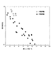
図2は、ラジアル玉軸受の転がり疲れ寿命(回転輪又は固定輪の寿命)と、運転時の玉の乗り上げ率との関係を調べる為に行なった実験の結果を示している。実験では、試料となるラジアル玉軸受として、外輪と内輪とで運転時の玉の乗り上げ率(計算値)が互いにほぼ等しく、且つ、玉の乗り上げが生じない前提での転がり疲れ寿命(計算値)が内輪に比べて外輪の方が長い、アンギュラ型のラジアル玉軸受を使用した。そして、この様なラジアル玉軸受を、外輪固定・内輪回転で、且つ、外輪と内輪とにそれぞれ玉の乗り上げが生じる状態で運転した。尚、この為に運転中、上記ラジアル玉軸受に、ラジアル荷重やモーメント荷重等の不等分布荷重を負荷した。尚、運転時の玉の乗り上げ率は、試料となる39個のラジアル玉軸受毎に少しずつ変えた。そして、これら各ラジアル玉軸受が寿命に達する(即ち、外輪と内輪とのうちの何れか一方の軌道輪の軌道面に剥離が生じる事に基づき、当該ラジアル玉軸受の振動又は温度が著しく上昇する)までの時間を測定すると共に、外輪と内輪とのうちの何れの軌道輪の軌道面に剥離が生じたかを調べた。
【0007】
実験の結果、図2に示す様に、玉の乗り上げが生じない前提での寿命の計算値が内輪に比べて外輪の方が長いにも拘らず、試料として用いた39個のラジアル玉軸受のうち、大半(30個)のラジアル玉軸受が、回転輪である内輪の軌道面(内輪軌道)よりも先に固定輪である外輪の軌道面(外輪軌道)に剥離を生じた。尚、一般的に、運転時にラジアル荷重やモーメント荷重等の不等分布荷重を受けるラジアル玉軸受の場合、回転輪よりも固定輪の方が軌道面に剥離を生じやすい。この理由は、回転輪の場合には、運転時に負荷圏が軌道面の円周方向に移動するのに対し、固定輪の場合には、運転時に負荷圏が軌道面の円周方向に移動せず、軌道面の同一個所で常に大きな繰り返し応力を受ける為である。
【0008】
又、図2に示した実験結果から明らかな通り、運転時の玉の乗り上げ率が大きくなる程、回転輪である内輪の軌道面よりも先に固定輪である外輪の軌道面に剥離が生じ易くなり、且つ、ラジアル玉軸受の相対寿命比(特定の試料の寿命を1としてそれに対する比率で表した、寿命を表す値)が小さくなる事が分かる。そこで、この様な実験結果を分析すると、固定輪である外輪に就いて運転時の玉の乗り上げ率が小さくなる様にすれば、この外輪の軌道面に剥離を生じにくくでき、ラジアル玉軸受全体としての寿命の延長を図れる事が分かる。
【0009】
尚、上述の様に運転時の玉の乗り上げ率を小さくする方法、即ち、軌道の幅方向端縁に玉の転動面が乗り上がりにくくする方法としては、当該軌道の曲率半径を大きくして、当該軌道と上記玉の転動面との接触部に存在する接触楕円の面積を小さくする方法と、当該軌道の幅方向側方に存在する肩部の高さを高くする方法とがある。このうち、軌道の曲率半径を大きくする方法は、この軌道の曲率半径を大きくする事に伴って接触部の面圧が上昇する為、転がり疲れ寿命を確保する観点から採用するのが難しい場合がある。又、肩部の高さを高くする方法は、この肩部と保持器9(図1参照)等の他の部材との干渉防止を図る為、制限を受ける場合がある。従って、軌道の幅方向端縁に玉の転動面を乗り上がりにくくさせる設計は、当該軌道の曲率半径と上記肩部の高さとの双方の値を調整しつつ、行なう必要がある。一方、上述の様な場合に、固定輪である外輪と同じ分だけ、回転輪である内輪に就いても運転時の玉の乗り上げ率を小さくすれば、この内輪の寿命も延長する可能性がある。但し、現状のままで十分な寿命を有する、回転輪である内輪の寿命を更に延長すベく、玉の乗り上げ率を小さくしても、この回転輪が過剰品質となるだけでなく、接触部の面圧が上昇して、かえって別の面から寿命を短くしたり(内輪軌道の曲率半径を大きくした場合)、肩部と保持器とが干渉する(肩部の高さを大きくした場合)等の問題が生じる為、好ましくない。
本発明は、上述の様な事情に鑑みて、玉の転動面と各軌道との接触部の面圧上昇を抑えたり、肩部と、保持器等他の部材との干渉を防止しながら、固定輪である外輪と回転輪である内輪との軌道面の曲率半径及び肩部の高さを調節する事により、これら外輪と内輪との寿命のバランスを取りつつ、複列ラジアル玉軸受全体としての寿命の延長を図るべく発明したものである。
【0010】
【課題を解決するための手段】
本発明の複列ラジアル玉軸受は、前述の図1に示した複列ラジアル玉軸受1と同様、内周面にアンギュラ型の外輪軌道を複列に形成した外輪と、それぞれの外周面にアンギュラ型の内輪軌道を形成した1対の内輪と、上記各外輪軌道とこれら各内輪軌道との間にそれぞれ転動自在に設けられた複数個の玉とを備える。そして、上記外輪が使用時にも回転しない固定輪であり、上記両内輪が使用時に回転する回転輪である。
特に、本発明の複列ラジアル玉軸受に於いては、自動車の車輪を懸架装置に対して回転自在に支持する為に使用し、上記複列に配置された上記各玉に背面組み合わせ型の接触角を付与している。そして、上記各外輪軌道の曲率半径をro とし、上記各内輪軌道の曲率半径をr i とし、上記各玉の直径をDとし、これら各玉の転動面と上記外輪、内輪各軌道との接触角をαとし、上記各外輪軌道の幅方向側方に設けられた肩部の、当該軌道の溝底からの径方向高さをHo とし、上記各内輪軌道の幅方向側方に設けられた肩部の、当該軌道の溝底からの径方向高さをHi とした場合に、次の(1)、(2)の条件を満たす。
(1)上記各外輪軌道の曲率半径ro 及び上記各内輪軌道の曲率半径ri と上記各玉の直径Dとの比(ro /D)、(ri /D)が、それぞれ(ro /D)=0.51〜0.54、及び、(ri /D)=0.51〜0.54の範囲内にあり、且つ、(ro /D)>(ri /D)の関係を満たす。
(2)H o が、H i よりも小さく、且つ、式「H o =(1.07〜1.15)×r o (1− cos (α+ sin -1 (r i ・ sin ( cos -1 (1−H i /r i )−α)×(−7.215(r o /r i )+8.187)/r o )))」を満たす範囲内にある。
【0012】
【作用】
上述の様に構成する本発明の複列ラジアル玉軸受によれば、運転時の玉の乗り上げ率が回転輪である内輪に比べて固定輪である外輪の方で小さくなり、外輪軌道に早期に剥離が生じる事を防止できる。この結果、外輪と内輪との寿命のバランスを取りつつ、複列ラジアル玉軸受全体としての寿命の延長を図れる。
【0013】
尚、複列ラジアル玉軸受を構成する外輪軌道と内輪軌道とのうちの内輪軌道は、円周方向に関して凸に湾曲している為、この内輪軌道と玉の転動面との接触部に存在する接触楕円の面積が(円周方向に存在する短径が短くなる為)小さくなり易い。この為、接触部の面圧上昇を抑えるべく、上記内輪軌道の曲率半径を玉の転動面の曲率半径に近付けて小さくし、上記接触楕円の面積を十分に確保する必要がある。ところが、この様に内輪軌道の曲率半径を小さくすると、上記接触楕円の(円周方向に対し直角方向に存在する)長径(この内輪軌道の幅方向に関する幅)が大きくなる為、この内輪軌道の幅方向端縁に上記玉の転動面が乗り上げ易くなる。
【0014】
これに対して、上記外輪軌道は、円周方向に関して凹に湾曲している為、この外輪軌道と玉の転動面との接触部に存在する接触楕円の(円周方向に存在する短径が長くなる為)面積を確保し易い。この為、この外輪軌道の曲率半径を多少大きくしても、接触部の面圧上昇を抑える事ができる。この様に外輪軌道の場合には、その曲率半径を上記内輪軌道の曲率半径に比べて大きくできる為、上記接触楕円の長半径(上記外輪軌道の幅方向に関する幅)が小さくなり、この外輪軌道の幅方向端縁に玉の転動面が乗り上がりにくくなる。
【0015】
外輪固定・内輪回転で使用される複列ラジアル玉軸受の場合には、内輪軌道の幅方向端縁よりも、外輪軌道の幅方向端縁に玉の転動面が乗り上がりにくくする。そして、この為に、外輪軌道の幅方向側方に設けられた肩部の高さを高くするが、上述した様に外輪軌道の幅方向端縁には、玉の転動面が乗り上がりにくくなっている。この為、上記内輪軌道の幅方向端縁よりも、上記外輪軌道の幅方向端縁に玉の転動面が乗り上がりにくくする場合には、上記肩部の高さを少しだけ高くすれば良い。従って、この肩部と保持器等の他の部材との干渉防止を考慮する必要がある場合でも、この肩部の高さを所望通りに高くし易い。
【0016】
【実施例】
以下、本発明の実施例に就いて説明する。本実施例では、前述の図1に示した複列ラジアル玉軸受1に本発明を適用し、各玉6、6と各軌道2、4との接触部の面圧上昇を抑えながら、内輪軌道の幅方向片側に設けた肩部の高さと、外輪軌道の幅方向片側に設けた肩部の高さとを調節する。これにより、運転時に上記各玉6、6が、上記内輪軌道の幅方向片側の端縁よりも上記外輪軌道の幅方向片側の端縁に乗り上がりにくい構造とする。そして、固定輪である外輪と回転輪である内輪との寿命を互いにほぼ等しくしつつ、上記複列ラジアル玉軸受1全体としての寿命の延長を図る。以下の実施例は、上述の図1に加えて、図3〜8を参照しつつ説明する。
【0017】
本例は、上記図1に示した複列ラジアル玉軸受1を構成する各内輪5、5が使用時に回転する回転輪であり、外輪3が使用時にも回転しない固定輪である場合の実施例である。
本例では、上記玉6の直径D(図5)が9.5〜12.7mmの範囲にあり、玉列のピッチ円直径が44〜64.5mmの範囲にあり、外輪、内輪各軌道2、4と上記玉6の転動面との接触角α(図5)が40度であり、上記外輪軌道2の曲率半径ro (図3、6)及び上記内輪軌道4の曲率半径ri (図4、6)と上記玉6の直径Dとの比が、それぞれ(ro /D)=0.51〜0.54、(ri /D)=0.51〜0.54の範囲にある複列ラジアル玉軸受1を対象とする。
【0018】
この様な複列ラジアル玉軸受1の場合、上記外輪軌道2と上記玉6の転動面との接触部に存在する接触楕円(以下「外輪側の接触楕円」と言う。)の長軸方向の半径(以下「長半径」と言う。)をao (図5)とし、上記内輪軌道4と上記玉6の転動面との接触部に存在する接触楕円(以下「内輪側の接触楕円」と言う。)の長半径をai (図5)とした場合に、これら各長半径ao 、ai 同士の比(ao /ai )と、上記外輪、内輪各軌道2、4の曲率半径ro 、ri 同士の比(ro /ri )との間には、図7に示す様な直線関係(比例関係)、即ち、次の(1)式で表される関係が成立する。
(ao /ai )=−7.215(ro /ri )+8.187
−−−−−(1)
尚、上記各長半径ao 、ai の具体的数値は、玉軸受の技術分野で周知である、ヘルツの接触理論により求める事ができる。
【0019】
一方、内輪側の肩部8の高さ(上記内輪軌道4の溝底から、荷重を負荷可能な部分の端である、この肩部8の端縁までの径方向高さ)をHi (図4、6)とすると、上記内輪軌道4の曲率中心O4 を中心とする、この内輪軌道4の溝底と上記肩部8の端縁との間の角度θHi(図6)は、
θHi=cos -1(1−Hi /ri ) −−−−−(2)
となる。
又、上記外輪、内輪各軌道2、4と上記玉6の転動面との接触角はαであるから、上記内輪側の接触楕円の許容長半径(=上記玉6の転動面が内輪側の肩部8の端縁に乗り上げない範囲での、当該接触楕円の長半径ai の最大値)ai 、 lim は、
ai 、 lim =ri ・sin (θHi−α) −−−−−(3)
となる。
【0020】
一方、上記内輪側の接触楕円の長半径ai が上記許容長半径ai 、 lim である場合の、前記外輪側の接触楕円の長半径ao (この場合のao をao 、 ilimとする)は、前記(1)式より、
ao 、 ilim=ai 、 lim {−7.215(ro /ri )+8.187}
−−−−−(4)
となる。
【0021】
そして、この(4)式で表される長半径ao 、 ilimが、上記外輪側の接触楕円の許容長半径(=上記玉6の転動面が外輪側の肩部7の端縁に乗り上げない範囲での、当該接触楕円の長半径ao の最大値)となる場合の、外輪側の肩部7の高さ(上記外輪軌道2の溝底からこの肩部7の端縁までの径方向高さ)Ho (図3、6。尚、この場合のHo を必要最低高さHo 、 min とする)は、
Ho 、 min =ro (1−cos θHo) −−−−−(5)
となる。尚、この(5)式の右辺中のθHoは、図6に示す様に、上記外輪軌道2の曲率中心O2 を中心とする、この外輪軌道2の溝底と上記肩部7の端縁との間の角度であり、
θHo=α+sin-1 ( ao 、 ilim/ro ) −−−−−(6)
で表される。
【0022】
ここで、上記(5)式に、上記(2)〜(4)及び(6)式を代入すると、上記外輪側の肩部7の必要最低高さHo 、 min は、
Ho 、 min =ro (1−cos (α+sin -1(ri ・sin (cos-1 (1−Hi /ri )−α)×(−7.215(ro /ri )+8.187)/ro )))
−−−−−(7)
と表されるが、この(7)式を、(ro /D)=0.51〜0.54、(ri /D)=0.51〜0.54の範囲にある、諸元の異なる幾つかの複列ラジアル玉軸受1に就いて計算すると、図8に示す様な結果が得られ、この結果に示す直線関係(比例関係)から、次の近似式が得られる。
Ho 、 min =Hi {−6.131(ro /ri )+7.105}
−−−−−(8)
【0023】
そこで、本実施例では、回転輪である内輪5の肩部8の高さをHi とした場合に、固定輪である外輪3の肩部7の高さHo を上記必要最低高さHo 、 min よりも大きくする(Ho >Ho 、 min )事により、運転時に複数個の玉6、6が、上記回転輪である内輪5の肩部8の端縁よりも上記固定輪である外輪3の肩部7の端縁に乗り上げにくい構造として、上記複列ラジアル玉軸受1の長寿命化を図る。例えば、Ho =(1.07〜1.15)×Ho 、 min とすれば、上記複列ラジアル玉軸受1の長寿命化を図れると共に、上記外輪軌道2と上記内輪軌道4との実際の転がり疲れ寿命を互いにほぼ等しくできる(バランスの良い設計を行なえる)。
【0024】
上述の計算に基づいて設計を行なった複列ラジアル玉軸受1の6例(軸受a〜f)を、以下の表1に示す。
【表1】

この結果、上述した各軸受a〜fとも、本発明による肩部の寸法規制を行なう前に比べて、軸受全体の転がり疲れ寿命を1.5〜3倍程度伸ばす事ができた。
【0025】
【発明の効果】
本発明の複列ラジアル玉軸受は、以上に述べた通り構成され作用するので、固定輪である外輪と回転輪である内輪との寿命のバランスを取りつつ、複列ラジアル玉軸受全体としての寿命の延長を図れる。
【図面の簡単な説明】
【図1】 複列ラジアル玉軸受の1例である、アンギュラ型の複列ラジアル玉軸受の半部断面図。
【図2】 運転時の玉の乗り上げ率が回転輪と固定輪とで等しいラジアル玉軸受の耐久試験の結果を示す図。
【図3】 アンギュラ型の複列ラジアル玉軸受を構成する外輪の半部断面図。
【図4】 同じく、1対の内輪の半部側面図。
【図5】 接触角αと、接触楕円の長半径ai 、ao とを表した図。
【図6】 軌道の曲率半径ri 、ro と、肩部の高さHi 、Ho と、軌道の溝底と肩部の端縁との間の角度θHi、θHoとを表した図。
【図7】 外輪、内輪両軌道の曲率半径同士の比(ro /ri )と外輪側、内輪側両接触楕円の長半径同士の比(ao /ai )との関係を示すグラフ。
【図8】 外輪、内輪両軌道の曲率半径同士の比(ro /ri )と、外輪側の肩部の必要最低高さと内輪側の肩部の高さとの比(Ho 、 min /Hi )との関係を示すグラフ。
【符号の説明】
1 複列ラジアル玉軸受
2 外輪軌道
3 外輪
4 内輪軌道
5 内輪
6 玉
7 肩部
8 肩部
9 保持器[0001]
BACKGROUND OF THE INVENTION
The present invention relates to an improvement in a double-row radial ball bearing for rotatably supporting a wheel of an automobile with respect to a suspension device . In particular, the double-row radial ball bearing of the present invention ensures sufficient durability even when it is used under conditions where load, shaft inclination, and vibration are applied during operation.
[0002]
[Prior art]
For example, a double-row radial ball bearing 1 as shown in FIG. 1 is used to rotatably support the wheels of an automobile with respect to a suspension device. This double-row
[0003]
By the way, a large thrust load or moment load may be applied to the double row radial ball bearing 1 as described above during the operation of the automobile in addition to the radial load. On the other hand, in such a case, the rolling members of the
[0004]
Further, the increase in the surface pressure based on the edge load as described above is a ratio (= the area of the part / the area of the entire contact ellipse including the part. , "Take-up rate of balls"), the larger it becomes. Such an increase in surface pressure causes the rolling fatigue life of the double-row radial ball bearing 1 to be reduced. Therefore, when performing actual design, the load load conditions during operation are taken into consideration when the operation is performed. The riding rates of the
[0005]
[Problems to be solved by the invention]
In the case of the double-row radial ball bearing 1 as described above, for example, when an automobile tire rides on a curbstone or the like, the climbing rate of each of the
[0006]
FIG. 2 shows the results of an experiment conducted to examine the relationship between the rolling fatigue life of a radial ball bearing (the life of a rotating wheel or a fixed wheel) and the ball climbing rate during operation. In the experiment, as a sample radial ball bearing, the rolling-up fatigue life (calculated value) is based on the assumption that the running rate (calculated value) of the balls in the outer ring and the inner ring are almost equal to each other and no ball ride-on occurs. An angular type radial ball bearing with an outer ring longer than the inner ring was used. Such a radial ball bearing was operated in a state where the outer ring was fixed and the inner ring was rotated, and the outer ring and the inner ring were loaded with balls. For this purpose, during operation, the radial ball bearing was loaded with unevenly distributed loads such as radial loads and moment loads. Incidentally, the running rate of balls during operation was changed little by little for each of 39 radial ball bearings as samples. Each of these radial ball bearings reaches the end of its life (that is, the vibration or temperature of the radial ball bearing significantly increases based on the occurrence of separation on the raceway surface of either the outer ring or the inner ring. ), And which of the outer ring and inner ring the raceway surface was checked for peeling.
[0007]
As a result of the experiment, as shown in FIG. 2, the calculated values of the life on the premise that no balls run up are longer for the outer ring than for the inner ring, but the 39 radial ball bearings used as samples were used. Among them, the majority (30) of the radial ball bearings peeled off the raceway surface (outer ring raceway) of the outer ring as a fixed ring before the raceway surface (inner raceway) of the inner ring as a rotating wheel. In general, in the case of a radial ball bearing that receives an unevenly distributed load such as a radial load or a moment load during operation, the fixed ring is more likely to peel off the raceway surface than the rotating wheel. This is because, in the case of rotating wheels, the load zone moves in the circumferential direction of the raceway surface during operation, whereas in the case of fixed wheels, the load zone moves in the circumferential direction of the raceway surface during operation. This is because it always receives a large repetitive stress at the same location on the raceway surface.
[0008]
In addition, as is apparent from the experimental results shown in FIG. 2, as the ball riding rate during driving increases, the raceway surface of the outer ring, which is a fixed ring, is peeled off before the raceway surface of the inner ring, which is a rotating wheel. It can be seen that the relative life ratio of the radial ball bearing (the value representing the life represented by the ratio of the life of a specific sample as 1) is reduced. Therefore, when analyzing the results of such an experiment, it is possible to prevent the raceway surface of the outer ring from peeling off and reduce the overall radial ball bearing by reducing the ball riding rate during operation for the outer ring, which is a fixed ring. It can be seen that the lifetime can be extended.
[0009]
As described above, as a method of reducing the running rate of the ball during driving, that is, a method of making it difficult for the rolling surface of the ball to ride on the edge in the width direction of the track, the radius of curvature of the track is increased. There are a method of reducing the area of the contact ellipse existing at the contact portion between the track and the rolling surface of the ball, and a method of increasing the height of the shoulder portion present on the side in the width direction of the track. Of these, the method of increasing the radius of curvature of the track may be difficult to adopt from the viewpoint of securing a rolling fatigue life because the surface pressure of the contact portion increases as the radius of curvature of the track increases. is there. Further, the method of increasing the height of the shoulder portion may be restricted in order to prevent interference between the shoulder portion and other members such as the cage 9 (see FIG. 1). Therefore, the design for making it difficult for the ball rolling surface to get on the edge in the width direction of the track needs to be performed while adjusting both the radius of curvature of the track and the height of the shoulder. On the other hand, in the above-described case, the life of the inner ring may be extended if the ball riding rate during driving is reduced by the same amount as that of the outer ring that is a fixed ring. is there. However, the life of the inner ring, which is a rotating wheel that has a sufficient life as it is, should be further extended. The surface pressure of the bearing increases, shortening the life from another surface (when the radius of curvature of the inner ring raceway is increased), or the shoulder and the cage interfere (when the height of the shoulder is increased) This is not preferable because of problems such as the above.
In view of the circumstances as described above, the present invention suppresses an increase in the surface pressure of the contact portion between the ball rolling surface and each track, while preventing interference between the shoulder portion and other members such as a cage. , by adjusting the height of the curvature radius and a shoulder portion of the raceway surface of the inner ring is the outer ring and the rotating ring is a fixed ring, while balancing the life of the outer ring and the inner ring, the entire double row radial ball bearings The invention was invented to extend the life of the product.
[0010]
[Means for Solving the Problems]
The double-row radial ball bearing of the present invention is similar to the double-row
In particular, in the double-row radial ball bearing of the present invention, it is used for rotatably supporting the wheel of an automobile with respect to a suspension device, and a back combination type contact is made with each of the balls arranged in the double row. The corner is given. Then, the radius of curvature of each outer ring raceway is r o , the radius of curvature of each inner ring raceway is r i , the diameter of each ball is D, and the rolling surface of each ball, each outer ring, each race of inner ring, the contact angle as alpha, shoulder portion provided in the width direction side of each outer ring raceway, the radial height from the groove bottom of the track and H o, the width direction side of each inner ring raceway the provided shoulder portion, the radial height from the groove bottom of the track when the H i, the following (1) satisfies the condition (2).
(1) The ratios (r o / D) and (r i / D) of the curvature radius r o of each outer ring raceway and the curvature radius r i of each inner ring raceway to the diameter D of each ball are (r o / D) = 0.51-0.54 and (r i /D)=0.51-0.54, and (r o / D)> (r i / D) Satisfy the relationship.
(2) H o is smaller than H i and the expression “H o = (1.07-1.15) × r o (1− cos (α + sin −1 (r i · sin ( cos −1) (1-H i / r i ) −α) × (−7.215 (r o / r i ) +8.187) / r o ))) ”.
[0012]
[Action]
According to the double-row radial ball bearing of the present invention configured as described above, the running rate of the balls during operation is smaller in the outer ring that is a fixed ring than in the inner ring that is a rotating ring , so that the outer ring raceway is early It is possible to prevent peeling. As a result, while balancing the life of the outer ring and the inner ring, thereby to extend the life of the entire double row radial ball bearings.
[0013]
The inner ring raceway of the outer ring raceway and the inner ring raceway constituting the double-row radial ball bearing is convexly curved in the circumferential direction, and therefore exists at the contact portion between the inner ring raceway and the ball rolling surface. The area of the contact ellipse is likely to be small (because the minor axis existing in the circumferential direction becomes short). For this reason, in order to suppress an increase in the surface pressure of the contact portion, it is necessary to reduce the curvature radius of the inner ring raceway close to the curvature radius of the rolling surface of the ball and to secure a sufficient area of the contact ellipse. However, when the radius of curvature of the inner ring raceway is reduced in this way, the major axis (existing in a direction perpendicular to the circumferential direction) of the contact ellipse (width in the width direction of the inner ring raceway) becomes larger. It becomes easy for the rolling surface of the ball to ride on the edge in the width direction.
[0014]
On the other hand, since the outer ring raceway is concavely curved in the circumferential direction, a contact ellipse (short diameter existing in the circumferential direction) exists in the contact portion between the outer ring raceway and the ball rolling surface. It is easy to secure the area). For this reason, even if the radius of curvature of the outer ring raceway is slightly increased, an increase in the surface pressure of the contact portion can be suppressed. In this way, in the case of the outer ring raceway, the radius of curvature can be made larger than the curvature radius of the inner ring raceway, so the major radius of the contact ellipse (width in the width direction of the outer ring raceway) becomes smaller. It becomes difficult for the rolling surface of the ball to ride on the edge in the width direction.
[0015]
In the case of a double-row radial ball bearing used for outer ring fixation and inner ring rotation, the rolling surface of the ball is less likely to ride on the width direction end edge of the outer ring raceway than the width direction end edge of the inner ring raceway. For this reason, the height of the shoulder provided on the side in the width direction of the outer ring raceway is increased. As described above, the rolling surface of the ball is unlikely to ride on the edge in the width direction of the outer ring raceway. It has become. For this reason, in order to make it difficult for the rolling surface of the ball to ride on the edge in the width direction of the outer ring raceway than the edge in the width direction of the inner raceway, the height of the shoulder portion may be slightly increased. . Therefore, even when it is necessary to consider the prevention of interference between the shoulder portion and other members such as a cage, the height of the shoulder portion can be easily increased as desired.
[0016]
【Example】
Examples of the present invention will be described below. In this embodiment, the present invention is applied to the double-row
[0017]
In this example , the
In this example, the diameter D (FIG. 5) of the
[0018]
In the case of such a double-row
(A o / a i ) = − 7.215 (r o / r i ) +8.187
----- (1)
The specific numerical values of the major radii a o and a i can be obtained by Hertz's contact theory, which is well known in the technical field of ball bearings.
[0019]
On the other hand, the height of the
θ Hi = cos −1 (1−H i / r i ) −−−−− (2)
It becomes.
Further, since the contact angle between the outer ring and
a i, lim = r i · sin (θ Hi -α) ----- (3)
It becomes.
[0020]
On the other hand, when the long radius a i of the contact ellipse on the inner ring side is the allowable long radius a i , lim , the long radius a o of the contact ellipse on the outer ring side (in this case, a o is a o , ilim ) From the above equation (1)
a o , ilim = a i , lim {−7.215 (r o / r i ) +8.187}
----- (4)
It becomes.
[0021]
The major radii a o , ilim represented by the equation (4) are the allowable major radius of the contact ellipse on the outer ring side (= the rolling surface of the
H o , min = r o (1-cos θ Ho ) ----- (5)
It becomes. Note that θ Ho in the right side of the equation (5) is the end of the groove bottom of the
θ Ho = α + sin -1 ( a o, ilim / r o) ----- (6)
It is represented by
[0022]
Here, when the above formulas (2) to (4) and (6) are substituted into the above formula (5), the required minimum heights H o and min of the
H o, min = r o ( 1-cos (α + sin -1 (r i · sin (cos -1 (1-H i / r i) -α) × (-7.215 (r o / r i) +8 .187) / r o )))
----- (7)
Although this equation (7) is expressed in the range of (r o /D)=0.51 to 0.54, (r i /D)=0.51 to 0.54, When calculation is performed for several different double-row
H o , min = H i {−6.131 (r o / r i ) +7.105}
----- (8)
[0023]
Accordingly, in this embodiment, when the height of the
[0024]
Table 6 below shows six examples (bearings a to f) of the double-row
[Table 1]
As a result, each of the bearings a to f described above was able to extend the rolling fatigue life of the entire bearing by about 1.5 to 3 times compared to before the shoulder size control according to the present invention.
[0025]
【The invention's effect】
Since the double-row radial ball bearing of the present invention is configured and operates as described above, the life of the double-row radial ball bearing as a whole is obtained while balancing the life of the outer ring that is a fixed ring and the inner ring that is a rotating ring. Can be extended.
[Brief description of the drawings]
1 is an example of a double row radial ball bearing, semi-sectional view of a double row radial ball bearings of the angular type.
FIG. 2 is a diagram showing the results of a durability test of radial ball bearings in which the running rate of balls during operation is the same for rotating wheels and fixed wheels.
FIG. 3 is a half sectional view of an outer ring constituting an angular type double-row radial ball bearing.
FIG. 4 is also a half side view of a pair of inner rings.
FIG. 5 is a diagram showing a contact angle α and major radii a i and a o of a contact ellipse.
Angle theta Hi, and theta Ho table between 6 curvature of the track radius r i, and r o, the height H i of the shoulder, and H o, and the edge of the groove bottom and the shoulder of the track Figure.
FIG. 7 is a graph showing the relationship between the ratio (r o / r i ) between the curvature radii of both the outer ring and inner ring raceways and the ratio (a o / a i ) between the major radii of both the outer ring side and inner ring side contact ellipses. .
[FIG. 8] The ratio (r o / r i ) between the radii of curvature of both the outer ring and inner ring raceways and the ratio between the required minimum height of the outer ring side shoulder and the height of the inner ring side shoulder (H o , min / A graph showing the relationship with H i ) .
[Explanation of symbols]
DESCRIPTION OF
Claims (1)
(1)上記各外輪軌道の曲率半径ro 及び上記各内輪軌道の曲率半径ri と上記各玉の直径Dとの比(ro /D)、(ri /D)が、それぞれ(ro /D)=0.51〜0.54、及び、(ri /D)=0.51〜0.54の範囲内にあり、且つ、(ro /D)>(ri /D)の関係を満たし、
(2)H o が、H i よりも小さく、且つ、式「H o =(1.07〜1.15)×r o (1− cos (α+ sin -1 (r i ・ sin ( cos -1 (1−H i /r i )−α)×(−7.215(r o /r i )+8.187)/r o )))」を満たす範囲内にある、事を特徴とする複列ラジアル玉軸受。An outer ring in which angular outer ring raceways are formed in a double row on the inner peripheral surface, a pair of inner rings in which angular inner ring raceways are formed on each outer peripheral surface, and the outer ring raceways between these inner ring raceways. In a double-row radial ball bearing comprising a plurality of balls each provided so as to be capable of rolling, the outer ring being a fixed ring that does not rotate even when used, and the inner ring being a rotating ring that rotates when used. This double-row radial ball bearing is to support the wheels of the automobile so as to be rotatable with respect to the suspension device, and each of the balls arranged in the double-row is provided with a back combination type contact angle, The radius of curvature of each outer ring raceway is r o , the radius of curvature of each inner ring raceway is r i , the diameter of each ball is D, and the contact surface between the rolling surface of each ball and each raceway of the outer ring and inner ring The angle is α, and it is provided on the lateral side of each outer ring raceway. And the shoulder portion, the radial height from the groove bottom of the track and H o, shoulder portion provided in the width direction side of each inner ring raceway, the radial height from the groove bottom of the track If H i ,
(1) The ratios (r o / D) and (r i / D) of the curvature radius r o of each outer ring raceway and the curvature radius r i of each inner ring raceway to the diameter D of each ball are (r o / D) = 0.51-0.54 and (r i /D)=0.51-0.54, and (r o / D)> (r i / D) Satisfy the relationship
(2) H o is smaller than H i and the expression “H o = (1.07-1.15) × r o (1− cos (α + sin −1 (r i · sin ( cos −1) (1-H i / r i ) −α) × (−7.215 (r o / r i ) +8.187) / r o ))) ”” Radial ball bearing.
Priority Applications (1)
| Application Number | Priority Date | Filing Date | Title |
|---|---|---|---|
| JP2001327293A JP4131099B2 (en) | 2001-10-25 | 2001-10-25 | Double row radial ball bearing |
Applications Claiming Priority (1)
| Application Number | Priority Date | Filing Date | Title |
|---|---|---|---|
| JP2001327293A JP4131099B2 (en) | 2001-10-25 | 2001-10-25 | Double row radial ball bearing |
Publications (3)
| Publication Number | Publication Date |
|---|---|
| JP2003130060A JP2003130060A (en) | 2003-05-08 |
| JP2003130060A5 JP2003130060A5 (en) | 2005-05-19 |
| JP4131099B2 true JP4131099B2 (en) | 2008-08-13 |
Family
ID=19143544
Family Applications (1)
| Application Number | Title | Priority Date | Filing Date |
|---|---|---|---|
| JP2001327293A Expired - Fee Related JP4131099B2 (en) | 2001-10-25 | 2001-10-25 | Double row radial ball bearing |
Country Status (1)
| Country | Link |
|---|---|
| JP (1) | JP4131099B2 (en) |
Families Citing this family (5)
| Publication number | Priority date | Publication date | Assignee | Title |
|---|---|---|---|---|
| EP1722115B1 (en) | 2005-05-12 | 2015-10-07 | NTN Corporation | Wheel support bearing assembly |
| WO2008129799A1 (en) | 2007-04-04 | 2008-10-30 | Ntn Corporation | Bearing for wheel and bearing device adapted to be used for wheel and having the bearing |
| JP5097479B2 (en) * | 2007-08-29 | 2012-12-12 | Ntn株式会社 | Wheel bearing and wheel bearing device provided with the same |
| JP5166755B2 (en) * | 2007-04-04 | 2013-03-21 | Ntn株式会社 | Wheel bearing and wheel bearing device provided with the same |
| JP6376212B2 (en) * | 2014-02-27 | 2018-08-22 | 日本精工株式会社 | Angular contact ball bearings |
-
2001
- 2001-10-25 JP JP2001327293A patent/JP4131099B2/en not_active Expired - Fee Related
Also Published As
| Publication number | Publication date |
|---|---|
| JP2003130060A (en) | 2003-05-08 |
Similar Documents
| Publication | Publication Date | Title |
|---|---|---|
| CN100554005C (en) | Wheel hub and connector unit | |
| US8167501B2 (en) | Separator for bearing assemblies with cyclic loads | |
| CN102171469A (en) | Rotation support device for pinion shaft | |
| JP4131099B2 (en) | Double row radial ball bearing | |
| JPH11303882A (en) | Constant speed joint | |
| CA2153199C (en) | Ball bearing block having self-contained bearings | |
| KR102311257B1 (en) | A Rolling Bearing Having Variable Rated Capacity And A Roller Therefor | |
| JP4067191B2 (en) | Constant velocity joints and rolling bearing units with constant velocity joints | |
| JP3794008B2 (en) | Wheel bearing | |
| JP3905283B2 (en) | Rotating shaft support structure | |
| JP2006214456A (en) | Roller bearing | |
| JP4225006B2 (en) | Double row angular contact ball bearings for wheels | |
| JP2003049848A (en) | Ball bearing for supporting pulley | |
| CN113767227B (en) | Large-sized rolling bearing | |
| JP3892213B2 (en) | 4-point contact ball bearing | |
| JP2001090736A5 (en) | ||
| CN206812794U (en) | Vehicle Propeller Shaft Supporting Bracket structure | |
| JP2600054Y2 (en) | Crowned synthetic resin cage for miniature ball bearings | |
| JP2002120508A (en) | Hub unit for automobile | |
| JP2001082462A (en) | Double row ball bearing | |
| JP2000158905A (en) | Wheel bearing | |
| JP2000038003A (en) | Rolling bearing unit for wheel | |
| JP2007069838A (en) | Rolling bearing device | |
| CN203023301U (en) | Double-row angular contact bearing with high running accuracy | |
| JP4228178B2 (en) | Water pump bearing |
Legal Events
| Date | Code | Title | Description |
|---|---|---|---|
| A521 | Written amendment |
Free format text: JAPANESE INTERMEDIATE CODE: A523 Effective date: 20040709 |
|
| A621 | Written request for application examination |
Free format text: JAPANESE INTERMEDIATE CODE: A621 Effective date: 20040709 |
|
| A977 | Report on retrieval |
Free format text: JAPANESE INTERMEDIATE CODE: A971007 Effective date: 20070122 |
|
| A131 | Notification of reasons for refusal |
Free format text: JAPANESE INTERMEDIATE CODE: A131 Effective date: 20070522 |
|
| A521 | Written amendment |
Free format text: JAPANESE INTERMEDIATE CODE: A523 Effective date: 20070719 |
|
| A131 | Notification of reasons for refusal |
Free format text: JAPANESE INTERMEDIATE CODE: A131 Effective date: 20070828 |
|
| A521 | Written amendment |
Free format text: JAPANESE INTERMEDIATE CODE: A523 Effective date: 20071025 |
|
| A131 | Notification of reasons for refusal |
Free format text: JAPANESE INTERMEDIATE CODE: A131 Effective date: 20080212 |
|
| A521 | Written amendment |
Free format text: JAPANESE INTERMEDIATE CODE: A523 Effective date: 20080411 |
|
| TRDD | Decision of grant or rejection written | ||
| A01 | Written decision to grant a patent or to grant a registration (utility model) |
Free format text: JAPANESE INTERMEDIATE CODE: A01 Effective date: 20080430 |
|
| A01 | Written decision to grant a patent or to grant a registration (utility model) |
Free format text: JAPANESE INTERMEDIATE CODE: A01 |
|
| A61 | First payment of annual fees (during grant procedure) |
Free format text: JAPANESE INTERMEDIATE CODE: A61 Effective date: 20080513 |
|
| FPAY | Renewal fee payment (event date is renewal date of database) |
Free format text: PAYMENT UNTIL: 20110606 Year of fee payment: 3 |
|
| R150 | Certificate of patent or registration of utility model |
Ref document number: 4131099 Country of ref document: JP Free format text: JAPANESE INTERMEDIATE CODE: R150 Free format text: JAPANESE INTERMEDIATE CODE: R150 |
|
| FPAY | Renewal fee payment (event date is renewal date of database) |
Free format text: PAYMENT UNTIL: 20120606 Year of fee payment: 4 |
|
| FPAY | Renewal fee payment (event date is renewal date of database) |
Free format text: PAYMENT UNTIL: 20130606 Year of fee payment: 5 |
|
| FPAY | Renewal fee payment (event date is renewal date of database) |
Free format text: PAYMENT UNTIL: 20130606 Year of fee payment: 5 |
|
| FPAY | Renewal fee payment (event date is renewal date of database) |
Free format text: PAYMENT UNTIL: 20140606 Year of fee payment: 6 |
|
| LAPS | Cancellation because of no payment of annual fees |