JP4131055B2 - Anti-fouling method for wire mesh by electro-coating - Google Patents
Anti-fouling method for wire mesh by electro-coating Download PDFInfo
- Publication number
- JP4131055B2 JP4131055B2 JP15764399A JP15764399A JP4131055B2 JP 4131055 B2 JP4131055 B2 JP 4131055B2 JP 15764399 A JP15764399 A JP 15764399A JP 15764399 A JP15764399 A JP 15764399A JP 4131055 B2 JP4131055 B2 JP 4131055B2
- Authority
- JP
- Japan
- Prior art keywords
- wire mesh
- wire
- electrocoating
- mesh
- caco
- Prior art date
- Legal status (The legal status is an assumption and is not a legal conclusion. Google has not performed a legal analysis and makes no representation as to the accuracy of the status listed.)
- Expired - Lifetime
Links
Images
Classifications
-
- Y—GENERAL TAGGING OF NEW TECHNOLOGICAL DEVELOPMENTS; GENERAL TAGGING OF CROSS-SECTIONAL TECHNOLOGIES SPANNING OVER SEVERAL SECTIONS OF THE IPC; TECHNICAL SUBJECTS COVERED BY FORMER USPC CROSS-REFERENCE ART COLLECTIONS [XRACs] AND DIGESTS
- Y02—TECHNOLOGIES OR APPLICATIONS FOR MITIGATION OR ADAPTATION AGAINST CLIMATE CHANGE
- Y02A—TECHNOLOGIES FOR ADAPTATION TO CLIMATE CHANGE
- Y02A40/00—Adaptation technologies in agriculture, forestry, livestock or agroalimentary production
- Y02A40/80—Adaptation technologies in agriculture, forestry, livestock or agroalimentary production in fisheries management
- Y02A40/81—Aquaculture, e.g. of fish
Description
【0001】
【発明の属する技術分野】
本発明ははまち、たいなどの海水魚の養殖用いけすに用いられる金網の防汚方法に係り、特に金網を組成する針金にエレクトロコーティングを施し、それに付着するフジツボなどの海洋付着生物をエレクトロコーティングとともに剥離して除去するエレクトロコーティングによるいけす金網の防汚方法に関する。
【0002】
【従来の技術】
近年の我国の漁業は捕獲漁業から養殖漁業へと転換されつつあり、沿岸における養殖事業が現在活発に行われている。そして、このような養殖においては、魚が所定の養殖区域から逃げ出さないように魚網で養殖区域の周囲および底部を囲いいけすを構成して行っていた。
【0003】
いけすに使用する漁網は沈降性、水中での形態保持性などが優れている金網が多く使用される。金網は軟鋼の針金に亜鉛メッキを施したものを使用して作製したもので、針金の太さは4mm程度のものが多い。
【0004】
【発明が解決しようとする課題】
しかし、時間が経過するにつれて、養殖区域を包囲する魚網にはフジツボ、カキ、ムラサキガイの幼生等のような各種の海中生物が付着し繁殖してしまう。そして、海中生物が繁殖するとその分だけ魚網の網目の面積が小さくなり、閉塞されたような状態となる。そのような状態では、新鮮な海水は魚網の内部、すなわち、いけすの内部へ流入し難くなり、いけす内の海水に含有される酸素が不足して酸欠状態となってしまい、いけす内の養殖魚が餌を摂取しなくなったり死んだりすることがある。また、魚がこれらの付着した貝に触れると皮膚が傷つき、それがもとで病気になることもある。
【0005】
これに対し、海中生物が付着し繁殖するのを防ぐため、毒性を有する薬剤、たとえば、有機スズ化合物を塗料と共に魚網に塗り付けることが行われていた。しかし、毒性薬剤が海中に微量ずつ溶解し、環境汚染の問題が起るので近年は用いられなくなった。
【0006】
そこで、潜水夫がウォータジェットなどで年に数回除去作業を行っている。しかし、この作業は作業費が膨大であり、必要なときにすぐに作業ができるとは限らないという問題がある。
【0007】
また、魚網を導電性を有する化学繊維、たとえば、炭素、炭素を含有する樹脂で作製し、それに直流電源を接続して魚網に接触している海水を電気分解して塩素ガスや次亜塩素酸イオンを発生させ、海中生物の付着および繁殖を防ぐことが提案されている(実開平3−56363)。
【0008】
しかし、この方法では、漁網が電極になり軟鋼や亜鉛メッキ軟鋼の針金製であると溶出しまって使えないので、上述のように炭素繊維などの導電性の繊維を使用しなければならないが、そうすると水中での形態保持性などの問題があるとともに、漁網が高価になる問題がある。なお、特開平1−199530号にも同様の提案がなされているが、同様の問題がある。
【0009】
一方、本願発明の発明者等は海水中における鋼板の防食方法であるエレクトロコーティングが海洋付着生物の防汚にも有効であることを発見し、特許出願を行った(特願平10−232952号(未公開))。
【0010】
エレクトロコーティングは、鋼板をカソードとして微弱電流を通電することにより、海水中に存在するカルシウムイオンやマグネシウムイオンが鋼板表面にMg(OH)2 とCaCO3 の2層のエレクトロコーティングとして析出することを利用して防食するものである。すなわち、Mg(OH)2 層は、アルカリ性で防食効果があるが溶けやすく、CaCO3 は防食効果はないが溶けにくいので、この2層からなるエレクトロコーティングにより、実用的な防食が達成できる。そして、該エレクトロコーティングに海洋付着生物が付着した状態でカソードとアノードの間に一定以上の電流密度で電流を通電すると、エレクトロコーティングは付着した海洋付着生物とともに剥離して、きれいな電着膜表面が現れるという知見が得られたので上記出願を行ったものでる。
【0011】
本発明は従来技術の以上述べた問題点に鑑み、かつ、上記知見に基づいて案出されたもので、鋼板についての有効性が認められた防汚方法をいけす金網に応用したエレクトロコーティングによるいけす金網の防汚方法を提供することを目的とする。
【0012】
【課題を解決するための手段】
上記目的を達成するため本発明のエレクトロコーティングによるいけす金網の防汚方法は、海水中に浸漬したいけす金網に犠牲電極を貼付するとともに、いけす金網をカソードとし、それに対峙して配置したアノードとの間で通電することによりいけす金網の針金表面にCaCO3 ・Mg(OH)2 のエレクトロコーティングを析出させた後、犠牲電極による微弱電流によりエレクトロコーティングを生長させ、該エレクトロコーティングに付着した海洋付着生物をアノードといけす金網との間で、金網の針金の表面積当り1〜5A/m2 の電流密度で通電することによりエレクトロコーティングと共に剥離して除去するものである。
【0013】
次に、本発明の作用を説明する。
海水中に浸漬したいけす金網に直流電源の(−)側を接続してカソードとし、それに対峙して配置したアノードに直流電源の(+)側を接続して通電すると、いけす金網を組成する針金の表面に海水中に存在するカルシウムイオンやマグネシウムイオンが析出して、針金の表面付近にMg(OH)2 層、その外側にCaCO3 層が形成される。直流電源を切り犠牲電極によって金網に通電し続けるとエレクトロコーティングは厚くなって行くとともに、その表面に海洋付着生物が付着して生長し次第に厚くなる。海洋付着生物の厚さが増大し、いけすの性能が損われるようになったら金網の針金の表面積当り1〜5A/m2 の電流密度で通電する。そうすると、カソードである針金表面付近に水の電気分解により生じた(OH- )イオンが蓄積されエレクトロコーティングのMg(OH)2 層のPH値が上昇し、PH値が11を越えるとMg(OH)2 の粒子は(−)に荷電する性質があるのでカソードである針金表面と反発し合うことになり、エレクトロコーティングが針金表面から剥離し、海洋付着生物も一緒に針金表面から剥離し、きれいな電着膜表面が現れる。したがって、いけす金網の性能は元に戻り、潜水夫がウォータジェットにより金網を清掃する作業を省くことができる。
【0014】
【発明の実施の形態】
以下、発明の1実施形態について図面を参照しつつ説明する。
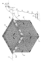
図1は本発明のエレクトロコーティングによるいけす金網の防汚方法を実施するための装置の全体斜視図である。図において、1はいけす金網である。いけす金網1の大きさは通常深さが8mで、8m角、10m角、15m角、20m角のものが多い。金網1cは通常、SS系の針金に亜鉛メッキが施されているもので構成されており、針金の太さは4mm程度のものを用いる。1aは鋼管製の枠体で4角形に形成されており、下面にフロート1bが取付けられていて、海面5に浮いている。
【0015】
金網1cは前後左右と底面の5面で形成されていて、前後左右の4面の金網の上端が枠体1aに固着されている。2は犠牲電極である。犠牲電極2の材質は亜鉛より卑な金属、たとえば、金属マグネシューム板であり、それを金網1c上に適当な間隔で貼付する。3はアノードであり、不溶解性あるいは溶解性の金属板で、いけす金網1と対峙して1または複数個設置する。4は直流電源であり(−)側をワイヤ6を介してカソードであるいけす金網1に接続し、(+)側をワイヤ6を介してアノード3に接続する。
【0016】
次に本実施形態の作用を説明する。
先ずエレクトロコーティングの生成について説明する。金網1をカソードとして海水中で通電すると、鋼板表面付近で水の電気分解反応により、水素と水酸イオンが発生する。水素は空気中に発散し、水酸イオンはPH値を上昇させる。PH値が8以上に上昇すると海水中のカルシウムイオンと炭酸イオンが結合し、炭酸カルシウム(CaCO3 )を形成する。PH値が9以上に上昇するとマグネシウムイオンと水酸イオンが結合し、水酸化マグネシウムMg(OH)2 を形成する。形成されたCaCO3 やMg(OH)2 の微粒子はコロイド状に鋼板表面近傍を浮遊しているが微粒子表面は(+)または(−)に荷電している。CaCO3 の粒子は、PHが9未満では(+)に荷電し、PHが9を越えると(−)に荷電する。一方、Mg(OH)2 の粒子はPHが11未満では(+)に荷電し、PHが11を越えると(−)に荷電する。また、カソードである針金表面の水酸イオン濃度は、表面で最も高く表面から遠ざかるにしたがって低下するので、針金表面近傍でPH値の勾配が生じている。この勾配の大きさはカソードの電流密度が大きいほど大きい。今適当な電流密度による通電により、針金表面のPH値が10程度であるとすると、Mg(OH)2 は(+)に荷電しているので電気泳動により表面に付着し、CaCO3 はそのPHでは(−)に荷電するので電気的に反発し、表面からわずかに離れる。わずかに離れた位置ではPH値は低下し9未満となっているのでCaCO3 は(+)に荷電しており、カソードに引き付けられて、そこに停滞する。このような原理により針金表面付近には、Mg(OH)2 の層が形成され、外側にCaCO3 の層が形成されて、CaCO3 ・Mg(OH)2 の2層のエレクトロコーティングが形成される。通電を続けると、Mg(OH)2 の層とCaCO3 の層はそれぞれ成長して厚さが厚くなるのであって、Mg(OH)2 の層とCaCO3 の薄い層が交互に積層するものではない。
【0017】
犠牲電極2は自ら海水中に溶解することにより金網1との間に電池を形成し、犠牲電極2と金網1との間に微弱な電流が流れ続ける。エレクトロコーティングはこの微弱電流(電流密度130〜200mA/m2 )によっても生成を続ける。
【0018】
次に、エレクトロコーティングの剥離について説明する。フジツボなどの海洋付着生物はこのようにして形成されたエレクトロコーティング表面に付着し、そこで成長し、次第に厚くなる。この状態で1〜5A/m2 の電流密度で通電し続けると次第に針金表面付近に水酸イオン(OH- )が蓄積されPH値が上昇する。PH値が11を越えるとMg(OH)2 の粒子は(−)に荷電するのでカソードの表面と反発し合うことになり、エレクトロコーティングが針金表面から剥離し、海洋付着生物も一緒に針金表面から剥離し、針金表面は元の状態に戻る。したがって、いけす金網の性能は元に戻り、潜水夫がウォータジェットにより金網を清掃する作業を省くことができる。
【0019】
なお、鋼板へのエレクトロコーティングによる防汚方法の原理および実証テストの結果については、先に述べた特願平10−232952号に詳しく説明されているので参照することができる。
【0020】
本発明は以上述べた実施形態に限定されるものではなく、発明の要旨を逸脱しない範囲で種々の変更が可能である。
【0021】
【発明の結果】
以上、述べたように本発明のエレクトロコーティングによるいけす金網の防汚方法は、金網をカソードとして通電することにより針金表面にエレクトロコーティングを生成させるとともに、金網に犠牲電極を貼付して微弱電を通電し続けてエレクトロコーティングを成長させ、エレクトロコーティングに海洋生物が付着して漁網としての性能が劣化したら、1〜5A/m2 の電流密度で通電することにより、海洋付着生物をエレクトロコーティングとともに剥離して除去するので、潜水夫がウォータジェットで海洋付着生物を除去する手間が省けるという優れた効果を有する。
【図面の簡単な説明】
【図1】本発明のエレクトロコーティングによる、いけす金網の防汚方法を実施するための装置の斜視図である。
【符号の説明】
1 いけす金網
2 犠牲電極
3 アノード
4 直流電源[0001]
BACKGROUND OF THE INVENTION
The present invention relates to an antifouling method for a wire mesh used for fishery for sea fish such as sea bream, sea bream, etc., and in particular, an electrocoating is applied to a wire composing the wire net, and marine adhering organisms such as barnacles attached thereto are peeled off together with the electrocoating. The present invention relates to an antifouling method for skeins of wire mesh by electrocoating to be removed.
[0002]
[Prior art]
In recent years, our country's fishery has been shifting from capture fishery to aquaculture, and aquaculture business is currently being carried out on the coast. In such aquaculture, a fish net is configured to surround the periphery and bottom of the aquaculture area so that the fish does not escape from the predetermined aquaculture area.
[0003]
The fishing nets used for ikeboku are often made of wire nets that are excellent in sedimentation and form retention in water. The wire mesh is produced by using a galvanized steel wire, and the wire has a thickness of about 4 mm in many cases.
[0004]
[Problems to be solved by the invention]
However, as time passes, various marine organisms such as barnacles, oysters, mussel larvae, etc., attach to the fish nets surrounding the aquaculture area and propagate. And when marine organisms propagate, the area of the mesh of the fish net is reduced by that amount, resulting in a state of being blocked. In such a state, fresh seawater does not easily flow into the inside of the fishnet, that is, the inside of the sashimi, and the oxygen contained in the seawater in the sardine becomes deficient, resulting in an oxygen deficient state. Fish may stop eating or die. In addition, when fish touch these attached shellfish, the skin can be damaged, which can cause illness.
[0005]
On the other hand, in order to prevent marine organisms from attaching and breeding, a toxic agent such as an organic tin compound is applied to a fish net together with a paint. However, in recent years, toxic drugs have been dissolved in the sea in minute amounts, causing environmental pollution problems, and have not been used in recent years.
[0006]
Therefore, divers perform removal work several times a year with water jets. However, this work has a problem that the work cost is enormous, and it is not always possible to work immediately when necessary.
[0007]
In addition, the fishnet is made of conductive chemical fibers, such as carbon and carbon-containing resin, and a direct current power source is connected to it to electrolyze the seawater in contact with the fishnet to produce chlorine gas or hypochlorous acid. It has been proposed to generate ions and prevent the attachment and propagation of marine organisms (Japanese Utility Model Publication No. 3-56363).
[0008]
However, in this method, if the fishing net becomes an electrode and is made of mild steel or galvanized mild steel wire, it cannot be used because it elutes, so conductive fibers such as carbon fiber must be used as described above. In addition to problems such as form retention in water, fishing nets are expensive. Although a similar proposal is made in Japanese Patent Laid-Open No. 1-1199530, there are similar problems.
[0009]
On the other hand, the inventors of the present invention discovered that electrocoating, which is an anticorrosion method for steel sheets in seawater, is also effective for antifouling of marine organisms, and filed a patent application (Japanese Patent Application No. 10-232952). (Unpublished)).
[0010]
Electrocoating utilizes the fact that calcium ions and magnesium ions present in seawater are deposited on the steel plate surface as a two-layer electrocoating of Mg (OH) 2 and CaCO 3 by applying a weak current to the steel plate as a cathode. To prevent corrosion. That is, the Mg (OH) 2 layer is alkaline and has an anticorrosive effect, but is easily soluble, and CaCO 3 has no anticorrosive effect but is hardly soluble. Therefore, practical anticorrosion can be achieved by electrocoating comprising these two layers. Then, when a current is passed between the cathode and the anode with a current density of a certain level or more with marine adhering organisms attached to the electrocoating, the electrocoating peels off with the adhering marine adhering organisms, and a clean electrodeposition film surface is formed. Since the knowledge of appearing was obtained, the above application was filed.
[0011]
The present invention has been devised in view of the above-described problems of the prior art and based on the above-mentioned knowledge, and is performed by electrocoating applied to a wire mesh that uses an antifouling method that is recognized as being effective for steel sheets. It aims at providing the antifouling method of a wire mesh.
[0012]
[Means for Solving the Problems]
In order to achieve the above object, the method for preventing fouling of a wire mesh by electrocoating according to the present invention includes attaching a sacrificial electrode to a wire mesh immersed in seawater, and using the wire mesh as a cathode and an anode disposed opposite thereto. After depositing an electrocoating of CaCO 3 · Mg (OH) 2 on the surface of the wire mesh wire that is energized between the electrodes, the electrocoating is grown by the weak current generated by the sacrificial electrode, and the marine adhering organism attached to the electrocoating Is peeled off together with the electrocoating by passing an electric current between the anode and the wire mesh at a current density of 1 to 5 A / m 2 per wire mesh surface area.
[0013]
Next, the operation of the present invention will be described.
Connect the (−) side of the DC power source to the wire mesh immersed in sea water to make the cathode, and connect the (+) side of the DC power source to the anode placed opposite to it to energize the wire that composes the wire mesh Calcium ions and magnesium ions present in seawater are deposited on the surface of the metal, and an Mg (OH) 2 layer is formed near the surface of the wire, and a CaCO 3 layer is formed on the outside thereof. When the DC power supply is turned off and the wire mesh is continuously energized by the sacrificial electrode, the electrocoating becomes thicker, and marine-adhering organisms adhere to the surface and grow and become thicker. When the thickness of marine adhering organisms increases and sacrificial performance is impaired, current is applied at a current density of 1 to 5 A / m 2 per surface area of the wire mesh wire. Then, (OH − ) ions generated by electrolysis of water are accumulated in the vicinity of the surface of the wire serving as the cathode, the PH value of the Mg (OH) 2 layer of the electrocoating increases, and when the PH value exceeds 11, Mg (OH ) Since the particles in ( 2 ) have the property of being charged (-), they will repel the surface of the cathode wire, the electrocoating will peel off from the wire surface, and marine adhering organisms will peel off from the surface of the wire together. The electrodeposition film surface appears. Therefore, the performance of the wire mesh is restored, and the work of the diver cleaning the wire mesh with the water jet can be omitted.
[0014]
DETAILED DESCRIPTION OF THE INVENTION
Hereinafter, an embodiment of the invention will be described with reference to the drawings.
FIG. 1 is an overall perspective view of an apparatus for carrying out a method for preventing fouling of a sushi wire net by electrocoating according to the present invention. In the figure, reference numeral 1 denotes a wire mesh. The size of the metal mesh 1 is usually 8 m deep, and is often 8 m square, 10 m square, 15 m square, and 20 m square. The
[0015]
The
[0016]
Next, the operation of this embodiment will be described.
First, generation of the electrocoating will be described. When the metal mesh 1 is used as a cathode and energized in seawater, hydrogen and hydroxide ions are generated by electrolysis of water near the steel plate surface. Hydrogen emanates into the air, and hydroxide ions raise the pH value. When the PH value rises to 8 or more, calcium ions and carbonate ions in seawater are combined to form calcium carbonate (CaCO 3 ). When the pH value increases to 9 or more, magnesium ions and hydroxide ions are combined to form magnesium hydroxide Mg (OH) 2 . The formed fine particles of CaCO 3 and Mg (OH) 2 float in the vicinity of the surface of the steel plate in a colloidal form, but the surface of the fine particles is charged to (+) or (−). The CaCO 3 particles are charged to (+) when PH is less than 9, and charged to (−) when PH exceeds 9. On the other hand, Mg (OH) 2 particles are charged to (+) when PH is less than 11, and charged to (−) when PH exceeds 11. Further, since the hydroxide ion concentration on the surface of the wire serving as the cathode is highest on the surface and decreases with increasing distance from the surface, a PH value gradient is generated in the vicinity of the wire surface. The magnitude of this gradient increases as the cathode current density increases. Assuming that the PH value of the wire surface is about 10 by energization with an appropriate current density, Mg (OH) 2 is charged to (+), so that it adheres to the surface by electrophoresis, and CaCO 3 has its PH value. Then, since it is charged to (-), it repels electrically and moves away from the surface slightly. At a slightly distant position, the PH value decreases to less than 9, so CaCO 3 is charged to (+) and is attracted to the cathode and stagnates there. Based on this principle, a Mg (OH) 2 layer is formed near the surface of the wire, a CaCO 3 layer is formed outside, and a two-layer electrocoating of CaCO 3 .Mg (OH) 2 is formed. The When energization is continued, the Mg (OH) 2 layer and the CaCO 3 layer grow and become thicker, and the Mg (OH) 2 layer and the CaCO 3 thin layer are alternately stacked. is not.
[0017]
The sacrificial electrode 2 itself dissolves in seawater to form a battery with the wire mesh 1, and a weak current continues to flow between the sacrificial electrode 2 and the wire mesh 1. Electrocoating continues to be generated by this weak current (current density 130-200 mA / m 2 ).
[0018]
Next, peeling of the electrocoating will be described. Marine adhering organisms such as barnacles attach to the electrocoating surface thus formed, grow there and become increasingly thick. In this state, when energization is continued at a current density of 1 to 5 A / m 2 , hydroxide ions (OH − ) are gradually accumulated near the surface of the wire and the PH value increases. If the PH value exceeds 11, the Mg (OH) 2 particles will be charged (-) and will repel the surface of the cathode, the electrocoating will peel off from the wire surface, and marine adhering organisms will also come together. The wire surface returns to its original state. Therefore, the performance of the wire mesh is restored, and the work of the diver cleaning the wire mesh with the water jet can be omitted.
[0019]
The principle of the antifouling method by electrocoating on the steel sheet and the results of the demonstration test are described in detail in the above-mentioned Japanese Patent Application No. 10-232952, and can be referred to.
[0020]
The present invention is not limited to the embodiments described above, and various modifications can be made without departing from the scope of the invention.
[0021]
Results of the Invention
As described above, the method for preventing fouling of a wire mesh by electrocoating according to the present invention generates an electrocoating on the surface of the wire by energizing the wire mesh as a cathode, and energizes a weak current by attaching a sacrificial electrode to the wire mesh. continues to the electrocoating grown Once degraded performance as fishing nets adhered marine organisms electrocoat, by energizing a current density of 1-5A / m 2, the marine fouling organisms was peeled off together with the electrocoat Therefore, it has an excellent effect that a diver can save time and effort to remove marine attached organisms with a water jet.
[Brief description of the drawings]
FIG. 1 is a perspective view of an apparatus for carrying out a method for preventing fouling of a wire mesh by electrocoating according to the present invention.
[Explanation of symbols]
1 Ikesu wire mesh 2 Sacrificial electrode 3 Anode 4 DC power supply
Claims (1)
Priority Applications (1)
| Application Number | Priority Date | Filing Date | Title |
|---|---|---|---|
| JP15764399A JP4131055B2 (en) | 1999-06-04 | 1999-06-04 | Anti-fouling method for wire mesh by electro-coating |
Applications Claiming Priority (1)
| Application Number | Priority Date | Filing Date | Title |
|---|---|---|---|
| JP15764399A JP4131055B2 (en) | 1999-06-04 | 1999-06-04 | Anti-fouling method for wire mesh by electro-coating |
Publications (2)
| Publication Number | Publication Date |
|---|---|
| JP2000342103A JP2000342103A (en) | 2000-12-12 |
| JP4131055B2 true JP4131055B2 (en) | 2008-08-13 |
Family
ID=15654217
Family Applications (1)
| Application Number | Title | Priority Date | Filing Date |
|---|---|---|---|
| JP15764399A Expired - Lifetime JP4131055B2 (en) | 1999-06-04 | 1999-06-04 | Anti-fouling method for wire mesh by electro-coating |
Country Status (1)
| Country | Link |
|---|---|
| JP (1) | JP4131055B2 (en) |
Families Citing this family (2)
| Publication number | Priority date | Publication date | Assignee | Title |
|---|---|---|---|---|
| NO313931B1 (en) * | 2001-03-08 | 2002-12-30 | Seafarm Dev As | Method and arrangement of cages |
| JP4424059B2 (en) * | 2004-05-11 | 2010-03-03 | 株式会社Ihi | Method for forming anticorrosion film |
-
1999
- 1999-06-04 JP JP15764399A patent/JP4131055B2/en not_active Expired - Lifetime
Also Published As
| Publication number | Publication date |
|---|---|
| JP2000342103A (en) | 2000-12-12 |
Similar Documents
| Publication | Publication Date | Title |
|---|---|---|
| US5346598A (en) | Method for the prevention of fouling and/or corrosion of structures in seawater, brackish water and/or fresh water | |
| JP6157150B2 (en) | Spawning reef and artificial fish reef | |
| US5643424A (en) | Apparatus for the prevention of fouling and/or corrosion of structures in seawater, brackish water and/or fresh water | |
| US5009757A (en) | Electrochemical system for the prevention of fouling on steel structures in seawater | |
| EP0985639A1 (en) | Electrochemical antifouling device comprising underwater structure and method of producing underwater structure used for the device | |
| EP0631637B1 (en) | Method and apparatus for the prevention of fouling and/or corrosion of structures in seawater, brackish water and/or fresh water | |
| JPH0724822B2 (en) | Antifouling method and antifouling device | |
| US5055165A (en) | Method and apparatus for the prevention of fouling and/or corrosion of structures in seawater, brackish water and fresh water | |
| JP4131055B2 (en) | Anti-fouling method for wire mesh by electro-coating | |
| KR20040073112A (en) | Anti-fouling and eliminating system for aquatic organisms | |
| JP4126513B2 (en) | Antifouling method and antifouling device by electrocoating | |
| JP2520779B2 (en) | Anticorrosion and antifouling method for underwater steel structures | |
| JPH0882609A (en) | Ocean environment-monitoring sensor system and controlling method thereof | |
| JPH11140677A (en) | Method for preventing contamination and local corrosion of wire net made of copper or copper alloy and device therefor | |
| JP4438158B2 (en) | Antifouling method for concrete structure and antifouling device for seawater conduit of concrete structure | |
| JP2004242617A (en) | Wire, wire net and crawl and method for producing the wire net | |
| JPH0325135B2 (en) | ||
| JPH0423406Y2 (en) | ||
| JPH0752167Y2 (en) | Replaceable energizing antifouling cover for offshore structures | |
| Usami et al. | Marine organism prevention system by electrolysis technology | |
| JPH11244861A (en) | Anti-fouling device for underwater structure and electrochemical control method of organism | |
| JPH02265421A (en) | Formation of seaweed bed | |
| JP4923375B2 (en) | Electrochemical antifouling method | |
| JPH02167914A (en) | Method for preventing pollution with electroconductive fiber | |
| JPS62164908A (en) | Control on organism adhered to water channel |
Legal Events
| Date | Code | Title | Description |
|---|---|---|---|
| A621 | Written request for application examination |
Free format text: JAPANESE INTERMEDIATE CODE: A621 Effective date: 20060524 |
|
| A977 | Report on retrieval |
Free format text: JAPANESE INTERMEDIATE CODE: A971007 Effective date: 20080417 |
|
| TRDD | Decision of grant or rejection written | ||
| A01 | Written decision to grant a patent or to grant a registration (utility model) |
Free format text: JAPANESE INTERMEDIATE CODE: A01 Effective date: 20080430 |
|
| A01 | Written decision to grant a patent or to grant a registration (utility model) |
Free format text: JAPANESE INTERMEDIATE CODE: A01 |
|
| A61 | First payment of annual fees (during grant procedure) |
Free format text: JAPANESE INTERMEDIATE CODE: A61 Effective date: 20080513 |
|
| FPAY | Renewal fee payment (event date is renewal date of database) |
Free format text: PAYMENT UNTIL: 20110606 Year of fee payment: 3 |
|
| R151 | Written notification of patent or utility model registration |
Ref document number: 4131055 Country of ref document: JP Free format text: JAPANESE INTERMEDIATE CODE: R151 |
|
| FPAY | Renewal fee payment (event date is renewal date of database) |
Free format text: PAYMENT UNTIL: 20110606 Year of fee payment: 3 |
|
| FPAY | Renewal fee payment (event date is renewal date of database) |
Free format text: PAYMENT UNTIL: 20110606 Year of fee payment: 3 |
|
| FPAY | Renewal fee payment (event date is renewal date of database) |
Free format text: PAYMENT UNTIL: 20120606 Year of fee payment: 4 |
|
| FPAY | Renewal fee payment (event date is renewal date of database) |
Free format text: PAYMENT UNTIL: 20120606 Year of fee payment: 4 |
|
| FPAY | Renewal fee payment (event date is renewal date of database) |
Free format text: PAYMENT UNTIL: 20130606 Year of fee payment: 5 |
|
| FPAY | Renewal fee payment (event date is renewal date of database) |
Free format text: PAYMENT UNTIL: 20140606 Year of fee payment: 6 |
|
| EXPY | Cancellation because of completion of term |