JP4130794B2 - Sash bottom frame - Google Patents

Sash bottom frame Download PDF

Info

Publication number
JP4130794B2
JP4130794B2 JP2003379963A JP2003379963A JP4130794B2 JP 4130794 B2 JP4130794 B2 JP 4130794B2 JP 2003379963 A JP2003379963 A JP 2003379963A JP 2003379963 A JP2003379963 A JP 2003379963A JP 4130794 B2 JP4130794 B2 JP 4130794B2
Authority
JP
Japan
Prior art keywords
indoor
outdoor
lower frame
shoji
resin
Prior art date
Legal status (The legal status is an assumption and is not a legal conclusion. Google has not performed a legal analysis and makes no representation as to the accuracy of the status listed.)
Expired - Fee Related
Application number
JP2003379963A
Other languages
Japanese (ja)
Other versions
JP2005139843A (en
Inventor
宏志 陶山
直孝 森
Original Assignee
新日軽株式会社
Priority date (The priority date is an assumption and is not a legal conclusion. Google has not performed a legal analysis and makes no representation as to the accuracy of the date listed.)
Filing date
Publication date
Application filed by 新日軽株式会社 filed Critical 新日軽株式会社
Priority to JP2003379963A priority Critical patent/JP4130794B2/en
Publication of JP2005139843A publication Critical patent/JP2005139843A/en
Application granted granted Critical
Publication of JP4130794B2 publication Critical patent/JP4130794B2/en
Anticipated expiration legal-status Critical
Expired - Fee Related legal-status Critical Current

Links

Images

Description

本発明は建物開口部に設けられ室内外障子を納めてなるサッシのサッシ下枠に関し、特に下枠の敷居面を略平坦に形成した下枠フラットサッシのサッシ下枠に関する。   The present invention relates to a sash lower frame of a sash that is provided at an opening of a building and accommodates indoor and outdoor shojis, and particularly relates to a sash lower frame of a lower frame flat sash in which a sill surface of the lower frame is formed substantially flat.

従来から、建物の出入口等に設けられる引き違い障子を納めたサッシにおいて、下枠に設けられる障子用のレールを室内側の床面と略同じ高さにして、車椅子でサッシを室内外方向に通過しやすくしたものが知られている。これは、レールの高さを略揃えていることにより、車椅子の車輪が比較的上下動することなくレール間を通過することができるようにしたものである。   Conventionally, in a sash that houses a sliding shoji installed at the entrance of a building, etc., the shoji rail provided on the lower frame is almost level with the floor on the indoor side, and the sash is moved indoors and outdoors with a wheelchair. Things that are easy to pass are known. This is because the wheel height of the wheelchair can pass between the rails without moving up and down relatively by making the height of the rails substantially the same.

また一方で、金属材からなるサッシの枠体及び障子の室内側露出部分を樹脂材にて略覆う複合サッシが広く用いられている。複合サッシはサッシの断熱性を確保することができると共に、樹脂材には様々な色や模様を付すことができるので、サッシの室内側における意匠性を高めることができるものである。以上のような下枠フラットサッシで、かつ複合サッシであるものとしては例えば特許文献1に示すようなものがある。
特開2003−176666号公報
On the other hand, a sash frame made of a metal material and a composite sash that covers the indoor side exposed portion of the shoji with a resin material are widely used. The composite sash can ensure the heat insulation of the sash, and the resin material can be provided with various colors and patterns, so that the design of the sash on the indoor side can be enhanced. As the above-described lower frame flat sash and the composite sash, there is one as shown in Patent Document 1, for example.
JP 2003-176666 A

しかし、従来のサッシ下枠においては、以下に述べる問題点を有していた。
複合サッシは通常、枠体を構成する上下枠及び左右の縦枠のいずれにおいても、室内側に露出する部分に樹脂材を設けることでデザインに統一性を持たせて意匠性を高めている。しかし、下枠フラットサッシでは、特許文献1にも示すように、下枠には樹脂材は設けられていなかった。したがって、下枠だけは金属材が露出することになるので、デザインの統一性が必ずしも取れていなかった。
However, the conventional sash lower frame has the following problems.
In general, the composite sash is provided with a resin material in a portion exposed to the indoor side in any of the upper and lower frames and the left and right vertical frames constituting the frame body, so that the design is unified and the design property is improved. However, in the lower frame flat sash, as shown in Patent Document 1, no resin material is provided on the lower frame. Therefore, since the metal material is exposed only in the lower frame, design uniformity has not necessarily been achieved.

本発明は、上記問題点を解決すべくなされたものであり、敷居面を略平坦にしつつも上枠や縦枠及び障子との調和の取れたサッシ下枠を提供することを目的とする。   The present invention has been made to solve the above-described problems, and an object of the present invention is to provide a sash lower frame in which the upper frame, the vertical frame, and the shoji are in harmony with the sill surface being substantially flat.

上記課題を解決するため、本発明に係るサッシ下枠は、室内外障子をそれぞれ走行自在に納めた枠体を構成し、上面を略平坦に形成したサッシ下枠において、
上記下枠の上面には室内障子を走行自在とする内走行部と室外障子を走行自在とする外走行部を設け、上記内走行部の室外側に室内障子を案内する内案内溝を形成すると共に、上記外走行部の室外側に室外障子を案内する外案内溝を形成し、
上記内走行部から下枠上面の室内側端部に渡って室内水平部を形成し、該室内水平部は水平状に形成された樹脂被覆部材に覆われ、上記外走行部から上記内案内溝に渡って室外水平部を形成し、該室外水平部は樹脂材からなる樹脂被覆部材に覆われ
上記下枠の室内側端部には室内側に突出するアングル片を設け、上記室内水平部を覆う樹脂被覆部材は上記アングル片の上面と略面一状であり、
上記室外水平部は該室外水平部を覆う樹脂被覆部材が上記室内水平部を覆う樹脂被覆部材と略同じ高さとなるように形成され、上記室外水平部を覆う樹脂被覆部材は上記内案内溝の側面を被覆し、該被覆する部分に内延出部が形成され、該内延出部は上記内案内溝内において室内側に向かって延出することを特徴として構成されている。
In order to solve the above-mentioned problem, the sash lower frame according to the present invention comprises a frame body in which indoor and outdoor shojis are stored so that they can run freely, and the upper surface of the sash lower frame is formed to be substantially flat.
An inner traveling portion for allowing the indoor shoji to travel and an outer traveling portion for allowing the outdoor shoji to travel are provided on the upper surface of the lower frame, and an inner guide groove for guiding the indoor shoji is formed outside the inner traveling portion. And forming an outer guide groove for guiding the outdoor shoji on the outdoor side of the outer running section,
An indoor horizontal portion is formed from the inner traveling portion to the indoor side end portion of the upper surface of the lower frame, the indoor horizontal portion is covered with a resin coating member formed in a horizontal shape, and the inner guiding groove is formed from the outer traveling portion. Forming an outdoor horizontal portion, the outdoor horizontal portion is covered with a resin coating member made of a resin material ,
An angle piece protruding to the indoor side is provided at the indoor side end of the lower frame, and the resin coating member covering the indoor horizontal part is substantially flush with the upper surface of the angle piece,
The outdoor horizontal portion is formed such that the resin coating member covering the outdoor horizontal portion is substantially the same height as the resin coating member covering the indoor horizontal portion, and the resin coating member covering the outdoor horizontal portion is formed by the inner guide groove. A side surface is covered, and an inner extension portion is formed in the portion to be covered, and the inner extension portion extends toward the indoor side in the inner guide groove .

さらに、本発明に係るサッシ下枠は、上記室内水平部を覆う樹脂被覆部材は上記アングル片と一体的に形成されてなることを特徴として構成されている。   Further, the sash lower frame according to the present invention is characterized in that a resin coating member that covers the indoor horizontal portion is formed integrally with the angle piece.

本発明に係るサッシ下枠によれば、下枠に室内水平部及び室外水平部を設けてそれが樹脂材からなる樹脂被覆部材に覆われることにより、下枠のフラット部分を大きくした上で、その室内露出部分を樹脂材にて覆って室内側からの見栄えをよくすることができ、サッシ全体としてのデザインを統一的にすることができる。   According to the sash lower frame according to the present invention, an indoor horizontal portion and an outdoor horizontal portion are provided in the lower frame, and the flat portion of the lower frame is enlarged by being covered with a resin coating member made of a resin material. The exposed portion of the room can be covered with a resin material to improve the appearance from the room side, and the design of the entire sash can be unified.

また、本発明に係るサッシ下枠によれば、室内水平部を覆う樹脂被覆部材はアングル片の上面と略面一状であることにより、内走行部よりも室内側を連続的に樹脂材にて覆うことができ、意匠性を向上させ、かつ断熱性も向上させることができる。さらに、室外水平部を覆う樹脂被覆部材は内案内溝の側面を被覆し、被覆する部分に内延出部が形成され、内延出部は内案内溝内において室内側に向かって延出することにより、内案内溝を見えにくくして意匠性を向上させることができる。 Further, according to the sash lower frame according to the present invention, the resin covering member covering the indoor horizontal portion is substantially flush with the upper surface of the angle piece, so that the indoor side is continuously made of the resin material from the inner traveling portion. It is possible to improve the design and heat insulation. Further, the resin coating member that covers the outdoor horizontal portion covers the side surface of the inner guide groove, and an inner extension portion is formed in the covered portion, and the inner extension portion extends toward the indoor side in the inner guide groove. This makes it difficult to see the inner guide groove and improves the design.

さらに、本発明に係るサッシ下枠によれば、室内水平部を覆う樹脂被覆部材はアングル片と一体的に形成されることにより、室内側に露出する樹脂部材を継ぎ目なく連続的とすることができ、意匠性を向上させることができる。   Further, according to the sash lower frame according to the present invention, the resin covering member covering the indoor horizontal portion is formed integrally with the angle piece, so that the resin member exposed to the indoor side can be made seamless and continuous. The design can be improved.

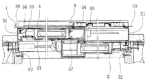
本発明の実施形態について図面に沿って詳細に説明する。図1は、本実施形態におけるサッシの縦断面図である。また、図2は、本実施形態におけるサッシの横断面図である。これら各図において、本実施形態におけるサッシは、建物開口部に装着された下枠10、上枠40、及び縦枠50、50からなる枠体1内に、下框30、上框45、及び縦框55、55を框組みしてガラスを納めてなる室内障子2及び室外障子3を引違い状に走行自在に納めると共に、室外障子3の室外側に網戸4を納めてなるものである。   Embodiments of the present invention will be described in detail with reference to the drawings. FIG. 1 is a longitudinal sectional view of a sash according to the present embodiment. FIG. 2 is a cross-sectional view of the sash in the present embodiment. In each of these drawings, the sash according to the present embodiment includes a lower frame 30, an upper frame 45, and an upper frame 45, and an upper frame 40, and vertical frames 50, 50 mounted in a building opening. The indoor shoji 2 and the outdoor shoji 3 in which the vertical screens 55 and 55 are assembled and housed in glass are housed in a sliding manner, and the screen door 4 is housed outside the outdoor shoji 3.

枠体1を構成する下枠10と上枠40及び縦枠50は、複合型の枠材であり、ベースとなる金属部材とその室内側露出部分を覆う樹脂部材とから構成されている。金属部材は、金属下枠11、金属上枠41、金属縦枠51、51を方形に枠組みして構成される。一方、樹脂部材は、金属上枠41に対して樹脂上枠42が、金属縦枠51、51に対して樹脂縦枠52、52が、それぞれ取付けられる。金属下枠11に対して取付けられる樹脂下枠12については、後で説明する。各金属部材には、それぞれ係止片が設けられ、樹脂部材はそれらに係合された上で、ネジによって固定される。   The lower frame 10, the upper frame 40, and the vertical frame 50 constituting the frame body 1 are composite type frame members, and are composed of a metal member serving as a base and a resin member that covers an exposed portion on the indoor side. The metal member is configured by forming a metal lower frame 11, a metal upper frame 41, and metal vertical frames 51, 51 into a rectangular frame. On the other hand, the resin member has a resin upper frame 42 attached to the metal upper frame 41 and resin vertical frames 52 and 52 attached to the metal vertical frames 51 and 51, respectively. The resin lower frame 12 attached to the metal lower frame 11 will be described later. Each metal member is provided with a locking piece, and the resin member is engaged with them and fixed with screws.

一方、室内障子2及び室外障子3は、上記枠体1と同様に金属部材とその室内側露出部分を略覆うように取付けられた樹脂部材とから構成されている。金属部材は、金属下框31、金属上框46、金属縦框56、56を方形に枠組みして構成され、樹脂部材は、樹脂下框32、樹脂上框47、樹脂縦框57、57から構成されている。そして、樹脂下框32は金属下框31に、樹脂上框47は金属上框46に、樹脂縦框57、57は金属縦框56、56に、それぞれ取り付けられている。各金属部材には、それぞれ係止片が設けられ、樹脂部材はそれらに係合された上で、ネジ及びカシメによって固定される。   On the other hand, the indoor shoji 2 and the outdoor shoji 3 are comprised from the metal member and the resin member attached so that the indoor side exposed part may be covered substantially similarly to the said frame 1. As shown in FIG. The metal member is configured by a rectangular framework of a metal lower collar 31, a metal upper collar 46, and metal longitudinal collars 56, 56, and the resin member includes a resin lower collar 32, a resin upper collar 47, and resin vertical collars 57, 57. It is configured. The resin lower bar 32 is attached to the metal lower bar 31, the resin upper bar 47 is attached to the metal upper bar 46, and the resin vertical bars 57 and 57 are attached to the metal vertical bars 56 and 56, respectively. Each metal member is provided with a locking piece, and the resin member is engaged with them and fixed by screws and caulking.

なお、枠体1と室内障子2及び室外障子3の金属部材は通常アルミの押出し型材にて成型され、また枠体1と室内障子2及び室外障子3の樹脂部材は塩化ビニルやアクリル樹脂等から成型される。このように樹脂部材にて金属部材の室内側露出部分を覆うことにより、金属による冷たい感じを隠し、また熱伝導率の低い樹脂によって断熱効果を向上させている。また、これらの樹脂材には、木材粉等を混入させて、外観上あたかも木材で形成されているかの観を呈することもできる。   The metal members of the frame 1 and the indoor shoji 2 and the outdoor shoji 3 are usually formed of an extruded material of aluminum, and the resin members of the frame 1 and the indoor shoji 2 and the outdoor shoji 3 are made of vinyl chloride, acrylic resin or the like. Molded. By covering the exposed portion of the metal member on the indoor side with the resin member in this way, the cold feeling due to the metal is hidden, and the heat insulation effect is improved by the resin having low thermal conductivity. In addition, these resin materials can be mixed with wood powder or the like to give an appearance as if they are formed of wood.

下枠10についてさらに詳細に説明する。図3には、下枠10の拡大図を示している。この図に示すように下枠10には、その上面、すなわち敷居面13に室内側から順に内レール14a、外レール14b、網戸レール14cがそれぞれ略同じ高さとなるように設けられている。内レール14aの室内側には、小溝16が形成されており、この小溝16にはその側面及び底面を略覆うように樹脂下枠12が設けられる。小溝16のさらに室内側、すなわち下枠10の室内側端部には、室内側の床面と連続するアングル部17が設けられる。このアングル部17は、樹脂下枠12と同様に樹脂材からなっている。アングル部17の上面は、下枠10の各レールと略同じ高さとなる。すなわち、下枠10の各レールは、室内側の床面と略同じ高さに形成されていることになる。   The lower frame 10 will be described in more detail. FIG. 3 shows an enlarged view of the lower frame 10. As shown in this figure, the lower frame 10 is provided with an inner rail 14a, an outer rail 14b, and a screen door rail 14c on the upper surface, that is, the sill surface 13, in order from the indoor side so as to have substantially the same height. A small groove 16 is formed on the indoor side of the inner rail 14a, and a resin lower frame 12 is provided in the small groove 16 so as to substantially cover the side surface and the bottom surface thereof. An angle portion 17 that is continuous with the floor surface on the indoor side is provided on the indoor side of the small groove 16, that is, on the indoor side end of the lower frame 10. The angle portion 17 is made of a resin material in the same manner as the resin lower frame 12. The upper surface of the angle portion 17 has substantially the same height as each rail of the lower frame 10. That is, each rail of the lower frame 10 is formed at substantially the same height as the floor surface on the indoor side.

内レール14aから網戸レール14cにかけては、長手方向略全長に渡って大溝15が形成されている。この大溝15に、外レール14bを備え、断面略コ字状に形成されてなる下枠補助部材20を長手方向略全長に渡って設け、それによって内レール14aの室外側に室内障子2を案内する内案内溝15aを形成すると共に、網戸レール14cの室内側に室外障子3を案内する外案内溝15bを形成する。大溝15の下面には、被係合部15cが形成されると共に、下枠補助部材20には係合部24が形成されており、それらを係合させ、さらにビス止めすることによって、下枠補助部材20を下枠10に対して固定する。   From the inner rail 14a to the screen door rail 14c, a large groove 15 is formed over substantially the entire length in the longitudinal direction. A lower frame auxiliary member 20 having an outer rail 14b and having a substantially U-shaped cross section is provided in the large groove 15 over substantially the entire length in the longitudinal direction, thereby guiding the indoor shoji 2 to the outdoor side of the inner rail 14a. The inner guide groove 15a is formed, and the outer guide groove 15b for guiding the outdoor shoji 3 is formed on the indoor side of the screen door rail 14c. An engaged portion 15 c is formed on the lower surface of the large groove 15, and an engaging portion 24 is formed on the lower frame auxiliary member 20. By engaging them and further screwing them, the lower frame The auxiliary member 20 is fixed to the lower frame 10.

下枠補助部材20は、上面に上述した外レール14bを備えると共に、その室内側には水平部21を備えている。水平部21は外レール14bから内案内溝15aまでの間を水平状としてなるものである。そして、この水平部21は、樹脂材からなる樹脂被覆部材22によって覆われている。図3に示すように、樹脂被覆部材22はその室内側端部から下方に垂下された垂下部22aを有しており、これによって水平部21だけでなく、下枠補助部材20の側面をも覆っている。さらに、垂下部22aの下端部は室内側に向かって略垂直に延出しており、これによって室内側から内案内溝15aの金属部分を見えにくくすることができ、サッシの意匠性を向上させることができる。   The lower frame auxiliary member 20 includes the outer rail 14b described above on the upper surface and a horizontal portion 21 on the indoor side. The horizontal portion 21 is formed horizontally between the outer rail 14b and the inner guide groove 15a. The horizontal portion 21 is covered with a resin coating member 22 made of a resin material. As shown in FIG. 3, the resin coating member 22 has a hanging portion 22 a that hangs downward from the indoor side end portion thereof, thereby not only the horizontal portion 21 but also the side surface of the lower frame auxiliary member 20. Covering. Furthermore, the lower end portion of the drooping portion 22a extends substantially vertically toward the indoor side, thereby making it difficult to see the metal portion of the inner guide groove 15a from the indoor side, and improving the design of the sash. Can do.

また、樹脂被覆部材22は、室内外障子2、3を閉じた状態において、水平部21の室内側に露出する部分のみを覆うようにしている。図4には下枠10の平面図を示している。この図に示すように、室内外障子2、3の召合せ部分に設けられる水密ブロック60よりも左側の部分にのみ樹脂被覆部材22を設けている。樹脂材は直射日光や風雨にさらされること等によって変色することがあり、このため樹脂被覆部材22を室内側露出部分のみに設けたことにより、その劣化を防ぐことができる。   In addition, the resin coating member 22 covers only the portion of the horizontal portion 21 exposed to the room side in the state where the indoor / outdoor shoji 2 and 3 are closed. FIG. 4 shows a plan view of the lower frame 10. As shown in this figure, the resin coating member 22 is provided only on the left side of the watertight block 60 provided at the summing portion of the indoor / outdoor shoji 2 and 3. The resin material may be discolored by being exposed to direct sunlight, wind and rain, etc. Therefore, by providing the resin coating member 22 only on the indoor side exposed portion, it is possible to prevent its deterioration.

また一方、水密ブロック60を挟んで反対側の室外側露出部分には、樹脂被覆部材22と略同形状で略同じ厚さの金属被覆部材25を設けている。図5には、金属被覆部材25が設けられる部分の下枠10の縦断面図を示す。この図に示すように、内案内溝15aの室内障子2が配置される部分には、下枠補助部材20の室内側面に下枠水密材63が設けられて、室内障子2の垂下片34に当接している。したがって、金属被覆部材25は下枠補助部材20の水平部21を覆うのみで、樹脂被覆部材22のように垂下部22aは有していない。   On the other hand, a metal covering member 25 having substantially the same shape and the same thickness as the resin covering member 22 is provided on the outdoor exposed portion on the opposite side across the watertight block 60. In FIG. 5, the longitudinal cross-sectional view of the lower frame 10 of the part in which the metal coating | coated member 25 is provided is shown. As shown in this figure, a portion of the inner guide groove 15 a where the indoor shoji 2 is disposed is provided with a lower frame watertight member 63 on the indoor side surface of the lower frame auxiliary member 20. It is in contact. Therefore, the metal covering member 25 only covers the horizontal portion 21 of the lower frame auxiliary member 20, and does not have the hanging portion 22 a unlike the resin covering member 22.

樹脂被覆部材22を水平部21に設けただけであると、水密ブロック60の左右で段差を生じることになるので、金属被覆部材25を設けることにより、この段差を解消することができる。また、下枠補助部材20は、それを既に枠組みした枠体1の下枠10に対して固定するために、左右端部付近を分割しておいて、まず左右端部を下枠10に納めた上で、残りの部分を挿入し固定する。したがって左右端部付近にそれぞれ分割線が生じるので、樹脂被覆部材22及び金属被覆部材25はいずれもそれら分割線を被覆し、室内側からの意匠性を高めることができる。さらに、金属被覆部材25を樹脂被覆部材22と同じ色に着色しておくことにより、室内障子2を開けた場合に室内側の樹脂部材との統一性を持たせることができる。   If only the resin coating member 22 is provided on the horizontal portion 21, a level difference is generated on the left and right sides of the watertight block 60. Therefore, the level difference can be eliminated by providing the metal coating member 25. Further, the lower frame auxiliary member 20 is divided in the vicinity of the left and right end portions in order to fix it to the lower frame 10 of the frame 1 that has already been framed, and the left and right end portions are first placed in the lower frame 10. Then, insert the remaining part and fix it. Therefore, since dividing lines are generated in the vicinity of the left and right end portions, both the resin coating member 22 and the metal coating member 25 can cover these dividing lines and enhance the design from the indoor side. Further, by coloring the metal covering member 25 in the same color as the resin covering member 22, it is possible to have uniformity with the indoor resin member when the indoor shoji 2 is opened.

さらに、図3に示すように下枠補助部材20にはその室外側端部に外延出部23を形成している。外延出部23は、外レール14bの室外側から外案内溝15b内に垂下され、さらにその下端部は室外側に向かって略垂直に延出している。外延出部23には室外障子3の下框30に設けられる下框水密材64に当接して、室外障子3の室内外方向の水密性を確保すると共に、外案内溝15bを直接見えにくいようにすることにより、サッシの意匠性を向上させている。   Further, as shown in FIG. 3, the lower frame auxiliary member 20 is formed with an outward extending portion 23 at the outdoor side end portion thereof. The outer extending portion 23 is suspended from the outdoor side of the outer rail 14b into the outer guide groove 15b, and the lower end portion extends substantially perpendicularly toward the outdoor side. The outer extension 23 is in contact with a lower watertight material 64 provided on the lower arm 30 of the outdoor shoji 3 to ensure the water tightness of the outdoor shoji 3 in the indoor / outdoor direction, and the outer guide groove 15b is difficult to see directly. By doing so, the design of the sash is improved.

室内外障子2、3の下框30について説明する。図3に示すように、内金属下框31aの室内側には内樹脂下框32aが、外金属下框31bの室内側には外樹脂下框32bが、それぞれ配設される。室内障子2と室外障子3はガラスの下端の高さが同じになるように、それぞれの下框30、30の上端の高さは同じとされている。また、室内外いずれの下框30、30にも、その下端部には内レール14a及び外レール14bを走行自在に摺動させるために戸車33、33が設けられている。   The lower arm 30 of the indoor / outdoor shoji 2, 3 will be described. As shown in FIG. 3, an inner resin lower rod 32a is disposed on the indoor side of the inner metal lower rod 31a, and an outer resin lower rod 32b is disposed on the indoor side of the outer metal lower rod 31b. The indoor shoji 2 and the outdoor shoji 3 have the same height at the upper ends of the lower collars 30 and 30 so that the lower end of the glass has the same height. In addition, doors 33 and 33 are provided at the lower ends of both the lower and upper armpits 30 and 30 in order to slide the inner rail 14a and the outer rail 14b movably.

内金属下框31aと外金属下框31bは、いずれも室外側下端部が戸車33、33の下端よりも下方まで垂下され、垂下片34、34を形成している。垂下片34、34はそれぞれ内案内溝15a及び外案内溝15b内に配置されて、室内障子2及び室外障子3をガイドする。さらに、垂下片34、34にはそれぞれ下框水密材64、64が設けられ、内金属下框31aの下框水密材64は内レール14aに、外金属下框31bの下框水密材64は下枠補助部材20の外延出部23にそれぞれ当接して、水の浸入を防いでいる。   The inner metal lower rod 31a and the outer metal lower rod 31b are both suspended from the lower end of the outdoor side to the lower side of the lower ends of the door wheels 33, 33 to form hanging pieces 34, 34. The hanging pieces 34 and 34 are disposed in the inner guide groove 15a and the outer guide groove 15b, respectively, to guide the indoor shoji 2 and the outdoor shoji 3. Further, the drooping pieces 34 and 34 are respectively provided with the lower metal watertight material 64, 64. The lower metal watertight material 64 of the inner metal lower metal rod 31a is provided on the inner rail 14a, and the lower metal watertight material 64 of the outer metal lower metal iron 31b is provided. The outer frame 23 is in contact with the outer extension 23 of the lower frame auxiliary member 20 to prevent water from entering.

内金属下框31aの室内側下端部は、戸車33の下端よりも下方まで垂下され、さらに内樹脂下框32aによりその室内側面及び下面を覆われている。これが小溝16内に配置されて垂下片34と共に室内障子2をガイドする。これら室内障子2の下框30の構成は、従来のサッシと同様であるので、内金属下框31a及び内樹脂下框32aはそれぞれ従来品をそのまま用いることができる。   The lower end portion on the indoor side of the inner metal lower rod 31a is suspended below the lower end of the door wheel 33, and the inner side surface and lower surface of the inner metal lower rod 32a are covered with the inner resin lower rod 32a. This is arranged in the small groove 16 and guides the indoor shoji 2 together with the hanging piece 34. Since the configuration of the lower collar 30 of the indoor shoji 2 is the same as that of the conventional sash, the inner metal lower collar 31a and the inner resin lower collar 32a can be used as they are.

外金属下框31bの室内側下端部には、戸車33の下端よりも上方であって、外レール14bと略同じ高さまで垂下した延出片35が形成されている。外樹脂下框32bは、上端が外金属下框31b及び室内障子2の下框30の上端と略同じ高さとされ、下端は外金属下框31bの延出片35に係止固定されると共に、下面は下枠補助部材20の水平部21を覆う樹脂被覆部材22と近接し、かつ対峙するように配置される。外樹脂下框32bとしては、上下端部がこれらの条件を満たすような既存の樹脂框を用いることができる。すなわち、下枠フラットサッシであっても、外金属下框31bだけは新規に製作する必要があるものの、それ以外の外樹脂下框32bや内金属下框31a及び内樹脂下框32aは既存の部品を用いることができる。   An extension piece 35 is formed at the lower end on the indoor side of the outer metal lower arm 31b, and extends downward from the lower end of the door wheel 33 to substantially the same height as the outer rail 14b. The outer resin lower collar 32b has an upper end substantially the same height as the outer metal lower collar 31b and the upper edge of the lower collar 30 of the indoor shoji 2, and the lower end is locked and fixed to the extension piece 35 of the outer metal lower collar 31b. The lower surface is disposed so as to be close to and confront the resin coating member 22 that covers the horizontal portion 21 of the lower frame auxiliary member 20. As the outer resin lower bar 32b, an existing resin bar whose upper and lower ends satisfy these conditions can be used. That is, even with the lower frame flat sash, only the outer metal lower bar 31b needs to be newly manufactured, but the other outer resin lower bar 32b, the inner metal lower bar 31a and the inner resin lower bar 32a are existing. Parts can be used.

次に、水密ブロック60について説明する。下枠10の内案内溝15a及び外案内溝15bは、長手方向略全長に渡って形成されており、室内障子2及び室外障子3はそれらのそれぞれ略半分の長さを有している。また、内案内溝15aと外案内溝15bの間には外レール14bと水平部21を有した下枠補助部材20が設けられるが、これを中間部5と称する。内外案内溝15a、15bは、それぞれ障子の召合せ部分に水密ブロック60を設けて分割することにより、浸入した水が召合せ部分の左右に渡って移動しないようにしている。図6には下枠10の水密ブロック60を設けた部分における縦断面図を示す。   Next, the watertight block 60 will be described. The inner guide groove 15a and the outer guide groove 15b of the lower frame 10 are formed over substantially the entire length in the longitudinal direction, and the indoor shoji 2 and the outdoor shoji 3 each have substantially half the length thereof. Also, a lower frame auxiliary member 20 having an outer rail 14b and a horizontal portion 21 is provided between the inner guide groove 15a and the outer guide groove 15b. The inner and outer guide grooves 15a and 15b are each divided by providing a watertight block 60 at the summing part of the shoji so that the intruded water does not move to the left and right of the summing part. FIG. 6 shows a vertical cross-sectional view of a portion where the watertight block 60 of the lower frame 10 is provided.

図6に示すように、水密ブロック60を設ける室内外障子2、3の召合せ部分においては、中間部5は外レール14bを残してそれ以外の部分を切り欠いた形状に形成されている。そして外レール14bの室内側、すなわち内レール14aから外レール14bにかけての空間に、断面形状がそれに略適合する内水密ブロック60aが設けられる。一方、外レール14bの室外側、すなわち外案内溝15bには断面形状においてそれに略適合する外水密ブロック60bが設けられる。   As shown in FIG. 6, in the summing part of the indoor / outdoor shoji 2 and 3 provided with the watertight block 60, the intermediate part 5 is formed in a shape in which the other part is cut out while leaving the outer rail 14b. An inner watertight block 60a having a substantially matching cross-sectional shape is provided on the indoor side of the outer rail 14b, that is, in a space from the inner rail 14a to the outer rail 14b. On the other hand, an outer watertight block 60b that substantially matches the cross-sectional shape is provided on the outdoor side of the outer rail 14b, that is, the outer guide groove 15b.

特に、中間部5を切り欠いて内レール14aから外レール14bにかけての空間に内水密ブロック60aを設けたことにより、内案内溝15aの左右の水密性だけでなく、下枠10と室外障子3の下框32との間の水密性も同時に確保することができる。また、中間部5を分割して中間部5内を流れる水が召合せ部分の左右に渡って移動しないようにしている。   Particularly, by providing the inner watertight block 60a in the space from the inner rail 14a to the outer rail 14b by cutting out the intermediate portion 5, not only the right and left watertightness of the inner guide groove 15a but also the lower frame 10 and the outdoor shoji 3 The watertightness between the lower arm 32 can be secured at the same time. Further, the intermediate portion 5 is divided so that the water flowing in the intermediate portion 5 does not move across the left and right of the summoned portion.

内水密ブロック60aは、室内障子2の室外側面と下端部に当接すると共に、室外障子3の下端部に当接する。内水密ブロック60aは内レール14aから外レール14bに渡って設けられているので、室内障子2と室外障子3のいずれにも当接することにより、1つのブロックで室内外障子2、3の召合せ部分における水密性を確保することができる。また、外水密ブロック60bは、室外障子3の室外側面及び下端部に当接する。   The inner watertight block 60 a abuts against the outdoor side surface and the lower end of the indoor shoji 2 and also abuts against the lower end of the outdoor shoji 3. Since the inner watertight block 60a is provided from the inner rail 14a to the outer rail 14b, the indoor / outdoor shoji 2 and 3 are summed up in one block by contacting both the indoor shoji 2 and the outdoor shoji 3 It is possible to ensure water tightness in the part. Further, the outer watertight block 60b contacts the outdoor side surface and the lower end of the outdoor shoji 3.

水密ブロック60には、その上面にヒレ状部61が形成されており、水密性を保ちながらも、室内外障子2、3を円滑に摺動させることができるようにされている。したがってこのヒレ状部61は、内水密ブロック60aでは室内障子2の垂下片34における室外側面と下端部に当接する部分、及び室外障子3の樹脂下框32の下端部に当接する部分にそれぞれ形成される。また、外水密ブロック60bでは室外障子3の垂下片34に当接する部分にヒレ状部61が形成される。   A fin-like portion 61 is formed on the upper surface of the watertight block 60 so that the indoor and outdoor shoji 2 and 3 can be smoothly slid while maintaining watertightness. Accordingly, the fin-like portion 61 is formed in the inner watertight block 60a at the portion that contacts the outdoor side surface and the lower end portion of the hanging piece 34 of the indoor shoji 2, and the portion that contacts the lower end portion of the resin lower collar 32 of the outdoor shoji 3, respectively. Is done. Moreover, the fin-shaped part 61 is formed in the part which contact | abuts the hanging piece 34 of the outdoor shoji 3 in the outdoor watertight block 60b.

ここで、外水密ブロック60bには、底面に切欠部62が形成されていて、外案内溝15b内に溜まった水が一部左右に移動できるようにされている。外案内溝15bの室外障子3が配置される部分には、下枠水密材63が設けられるため、雨水等が浸入してくる量は限られているのに対し、外案内溝15bの室外側露出部分は、直接雨水等にさらされるために、大量の水が浸入することになる。そのため、一部の水を外水密ブロック60bの切欠部62を介して移動させることにより、効率よく排水を行うことができる。一方で、内水密ブロック60aには切欠部62は形成されておらず、内案内溝15a内に溜まった水を略遮断することができるようにされている。   Here, the outer watertight block 60b has a notch 62 formed on the bottom surface, so that a part of the water accumulated in the outer guide groove 15b can move to the left and right. Since the lower frame watertight material 63 is provided at the portion of the outer guide groove 15b where the outdoor shoji 3 is disposed, the amount of rainwater or the like entering is limited, whereas the outside of the outer guide groove 15b is outside the outdoor guide groove 15b. Since the exposed portion is directly exposed to rainwater or the like, a large amount of water enters. Therefore, drainage can be efficiently performed by moving a part of the water through the cutout portion 62 of the outer watertight block 60b. On the other hand, the notch 62 is not formed in the inner watertight block 60a, and the water accumulated in the inner guide groove 15a can be substantially blocked.

次に、下枠10における排水構造について説明する。排水のために下枠10に設けられた全体的な構成は以下の通りである。雨水等にサッシがさらされると、下枠10に形成された各溝に水が溜まることになるので、各溝にはそれぞれ貫通孔82、83、84、85、86が設けられている。サッシに浸入した水は、各貫通孔82、83、84、85、86から下枠10の室外側面に形成された2つの排水孔80、81のうちいずれかを介して室外に排水される。   Next, the drainage structure in the lower frame 10 will be described. The overall configuration provided in the lower frame 10 for draining is as follows. When the sash is exposed to rain water or the like, water accumulates in each groove formed in the lower frame 10, and therefore, each groove is provided with through holes 82, 83, 84, 85, 86. The water that has entered the sash is drained from the through holes 82, 83, 84, 85, 86 to the outdoor through one of the two drain holes 80, 81 formed on the outdoor side surface of the lower frame 10.

図4に示すように、各溝を排水経路毎の領域に分けると、まず小溝16には水密ブロック60は配置されないので、その全域を領域70とする。内案内溝15aは内水密ブロック60aを境界として、室内側に露出する部分を領域71、室内障子2が配置される部分を領域72とする。外案内溝15bは外水密ブロック60bを境界として、室外側に露出する部分を領域73、室外障子3が配置される部分を領域74とする。各領域によって、排水経路が異なっている。水があまり浸入しない領域については、水を下枠10下部の中空部87に一旦落とした上で、第1排水孔80から排水される。水が大量に浸入する領域については、排水経路を極力短くして、下枠10の室外側面上部に形成される第2排水孔81から排水される。   As shown in FIG. 4, when each groove is divided into regions for each drainage path, first, the watertight block 60 is not disposed in the small groove 16, and thus the entire region is defined as a region 70. The inner guide groove 15a has the inner watertight block 60a as a boundary, a portion exposed to the indoor side as a region 71, and a portion where the indoor shoji 2 is disposed as a region 72. In the outer guide groove 15b, with the outer watertight block 60b as a boundary, a portion exposed to the outdoor side is a region 73, and a portion where the outdoor shoji 3 is disposed is a region 74. Each area has a different drainage route. In the region where water does not enter so much, the water is once dropped into the hollow portion 87 below the lower frame 10 and then drained from the first drain hole 80. About the area | region where water infiltrates in large quantities, it drains from the 2nd drainage hole 81 formed in the outdoor side surface upper part of the lower frame 10, shortening a drainage path as much as possible.

各領域の排水構造について詳細に説明する。図8には、下枠補助部材20を外した金属下枠11の平面図を示す。図5と図7には下枠10の縦断面図における各領域の排水経路が示されている。図5は内レール14aに室内障子2が配置される部分の縦断面図で、領域72及び領域73の排水経路を示している。図7は外レール14bに室外障子3が配置される部分の縦断面図で、領域70と領域71及び領域74の排水経路を示している。領域70は、サッシの室内側露出部分であって、下枠水密材63や下框水密材64よりも室内側に位置しているので、雨水等はほとんど浸入しない。そこで、上述のように領域70については、水を下枠10下部の中空部87に導いて、第1排水孔80から排水される第1排水経路90によって排水がなされる。まず、領域70に浸入した水は、内レール14aに形成された第5貫通孔86によって内案内溝15aに導かれる。図8に示すように、第5貫通孔86は内レール14aの室内露出部分にのみ形成されているので、領域70の水は領域71に導かれることになる。   The drainage structure in each area will be described in detail. FIG. 8 shows a plan view of the metal lower frame 11 with the lower frame auxiliary member 20 removed. 5 and 7 show drainage paths in the respective regions in the longitudinal sectional view of the lower frame 10. FIG. 5 is a longitudinal sectional view of a portion where the indoor shoji 2 is disposed on the inner rail 14a, and shows drainage paths in the region 72 and the region 73. FIG. FIG. 7 is a longitudinal sectional view of a portion where the outdoor shoji 3 is disposed on the outer rail 14 b, and shows drainage paths of the region 70, the region 71, and the region 74. The region 70 is an exposed portion on the indoor side of the sash, and is located on the indoor side of the lower frame watertight material 63 and the lower watertight material 64, so that rainwater or the like hardly enters. Therefore, as described above, in the region 70, water is led to the hollow portion 87 at the lower part of the lower frame 10, and drained by the first drainage path 90 drained from the first drainage hole 80. First, the water that has entered the region 70 is guided to the inner guide groove 15a by the fifth through hole 86 formed in the inner rail 14a. As shown in FIG. 8, since the fifth through hole 86 is formed only in the indoor exposed portion of the inner rail 14 a, the water in the region 70 is guided to the region 71.

領域71は、領域70と同様にサッシの室内側露出部分であって、室外障子3及び水密ブロック60によって室外側から直接水が浸入しにくくなっているので、領域70からの水と併せて第1排水経路90により排水がなされる。領域71からの水は、中間部5の室内側面に形成された第1貫通孔82によって、中間部5の内部に導かれる。また、図8に示すように、中間部5である下枠補助部材20が取付けられる下枠10の上面には第2貫通孔83が形成されており、領域71からの水を下枠10下部の中空部87に導く。さらに、中空部87に導かれた水は、下枠10の第1排水孔80から室外に排水される。以上のように、領域70及び領域71に浸入した水は、第1貫通孔82と第2貫通孔83とからなる第1水抜き孔を通って第1排水孔80から室外に排出される第1排水経路90により、排水される。   The area 71 is an exposed portion of the sash on the indoor side, like the area 70, and the outdoor shoji 3 and the watertight block 60 make it difficult for water to enter directly from the outdoor side. Drainage is performed by one drainage path 90. Water from the region 71 is guided to the inside of the intermediate part 5 by the first through hole 82 formed on the indoor side surface of the intermediate part 5. Further, as shown in FIG. 8, a second through hole 83 is formed on the upper surface of the lower frame 10 to which the lower frame auxiliary member 20 as the intermediate portion 5 is attached, and water from the region 71 is supplied to the lower portion of the lower frame 10. To the hollow portion 87. Further, the water guided to the hollow portion 87 is drained from the first drain hole 80 of the lower frame 10 to the outside of the room. As described above, the water that has entered the region 70 and the region 71 passes through the first drain hole composed of the first through hole 82 and the second through hole 83 and is discharged from the first drain hole 80 to the outside. The water is drained by one drainage path 90.

領域72は、中間部5に設けられる下枠水密材63によって水密されている。下枠水密材63は直接室外側に露出しているので、領域72に対するある程度の水の浸入は避けられない。そこで、領域72からの排水は、第2排水経路91を通って、下枠10の第2排水孔81から室外に排水される。まず、領域72に浸入した水は、中間部の室内側面に形成された第3貫通孔84によって中間部5の内部に導かれる。中間部5の召合せ部分は、上述のように外レール14bを残して切り欠かれ、そこに内水密ブロック60aが設けられているので、領域72からの水は第1排水経路90側には浸入しない。中間部5の内部に導かれた水は、中間部5の室外側面に形成された第4貫通孔85によって、さらに外案内溝15bに導かれる。そして、外案内溝15bの室外側面には第2排水孔81が形成されており、ここから室外に排水される。   The region 72 is watertight by a lower frame watertight member 63 provided in the intermediate portion 5. Since the lower frame watertight material 63 is directly exposed to the outside of the room, a certain amount of water intrusion into the region 72 is inevitable. Therefore, the drainage from the region 72 passes through the second drainage path 91 and is drained outside from the second drainage hole 81 of the lower frame 10. First, the water that has entered the region 72 is guided to the inside of the intermediate portion 5 by the third through hole 84 formed on the indoor side surface of the intermediate portion. The summing portion of the intermediate portion 5 is cut out with the outer rail 14b left as described above, and the inner watertight block 60a is provided there, so that water from the region 72 is not supplied to the first drainage path 90 side. Do not enter. The water guided to the inside of the intermediate part 5 is further guided to the outer guide groove 15b by the fourth through hole 85 formed on the outdoor side surface of the intermediate part 5. And the 2nd drain hole 81 is formed in the outdoor side surface of the outer guide groove 15b, and it drains outside from here.

領域74は、下枠10に設けられる下枠水密材63によって水密されている。したがって領域72と同様に、領域74にもある程度の水の浸入は避けられない。また、領域73は室外側に直接露出しているので、大量に水が浸入することになる。これらの領域は、領域72からの水と併せて第2排水経路91により室外に排水される。すなわち、領域73及び領域74に浸入した水は、外案内溝15bに設けられた第2排水孔81により直接室外に排水される。また、上述のように外水密ブロック60bには、底面に切欠部62が形成され、領域73と領域74の水は一部移動可能とされているので、大量の水が浸入する領域73の水が一部領域74に入って、排水されることにより、効率よく排水を行うことができる。以上のように、領域72と領域73及び領域74に浸入した水は、第3貫通孔84と第4貫通孔85とからなる第2水抜き孔を通って第2排水孔81から室外に排出される第2排水経路91により、排水される。   The region 74 is watertight by a lower frame watertight member 63 provided in the lower frame 10. Therefore, as in the region 72, a certain amount of water is unavoidable in the region 74. Further, since the region 73 is directly exposed to the outdoor side, a large amount of water enters. These areas are drained to the outside by the second drainage channel 91 together with the water from the area 72. That is, the water that has entered the region 73 and the region 74 is directly drained out of the room through the second drain hole 81 provided in the outer guide groove 15b. Further, as described above, the outer watertight block 60b has the notch 62 formed on the bottom surface, and part of the water in the region 73 and the region 74 is movable, so that the water in the region 73 into which a large amount of water enters. Can enter the region 74 and drain, so that drainage can be performed efficiently. As described above, the water that has entered the region 72, the region 73, and the region 74 is discharged out of the second drain hole 81 through the second drain hole formed by the third through hole 84 and the fourth through hole 85. The second drainage channel 91 is drained.

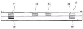
図9には、金属下枠11の側面図を示す。この図に示すように、金属下枠11の下部には第1排水孔80が左右端部付近にそれぞれ設けられている。また、金属下枠11の上部には第2排水孔81が左右端部及び中央付近にそれぞれ設けられている。第2排水孔81を用いる第2排水経路91は大量の水を室外に排水しなければならないので、第1排水孔80に比べて第2排水孔81をより多く配置している。さらに、図5や図7に示すように、第1排水孔80及び第2排水孔81には、水が室外側から逆流しないように排水弁88がそれぞれ設けられている。   FIG. 9 shows a side view of the metal lower frame 11. As shown in this figure, first drain holes 80 are provided in the vicinity of the left and right ends at the lower part of the metal lower frame 11. In addition, second drain holes 81 are provided in the upper part of the metal lower frame 11 near the left and right ends and the center. Since the second drainage passage 91 using the second drainage holes 81 has to drain a large amount of water to the outside, more second drainage holes 81 are arranged than the first drainage holes 80. Furthermore, as shown in FIG. 5 and FIG. 7, the first drain hole 80 and the second drain hole 81 are each provided with a drain valve 88 so that water does not flow backward from the outdoor side.

次に、上記第1実施形態の一部を変更した実施形態について説明する。図10には第2実施形態におけるサッシの縦断面図における下部拡大図を示す。本実施形態では、内レール14aの室内側に室内水平部18を設けている。すなわち、第1実施形態においては内レール14aの室内側には小溝16が形成されていたのに対して、その部分を室内水平部18としたことで、下枠10の凹凸をより少なくして平坦に近づけたものである。   Next, an embodiment in which a part of the first embodiment is changed will be described. FIG. 10 is an enlarged view of the lower part in the longitudinal sectional view of the sash in the second embodiment. In the present embodiment, the indoor horizontal portion 18 is provided on the indoor side of the inner rail 14a. That is, in the first embodiment, the small groove 16 is formed on the indoor side of the inner rail 14a, but the portion is the indoor horizontal portion 18, thereby reducing the unevenness of the lower frame 10. It is close to flat.

室内水平部18の上面は平面状に形成されてなる樹脂被覆部材26にて覆っている。外レール14bの室内側に設けられる樹脂被覆部材22と異なり、長手方向略全長に渡って設けられる。これによってサッシの意匠性を高めることができ、また断熱性も確保することができる。室内水平部18を覆う樹脂被覆部材26は、床面と略連続状となるアングル部17の上面と略連続状とされ、この点からも意匠性を向上させることができる。なお、本実施形態ではアングル部17と樹脂被覆部材26を別々に設けているが、これらを一体的に形成してもよい。アングル部17と樹脂被覆部材26が一体的に形成されることにより、継ぎ目がなく、より一体的なサッシとすることができて、意匠性をより向上させることができる。   The upper surface of the indoor horizontal portion 18 is covered with a resin coating member 26 formed in a planar shape. Unlike the resin coating member 22 provided on the indoor side of the outer rail 14b, it is provided over substantially the entire length in the longitudinal direction. By this, the design property of a sash can be improved and heat insulation can also be ensured. The resin coating member 26 covering the indoor horizontal portion 18 is substantially continuous with the upper surface of the angle portion 17 which is substantially continuous with the floor surface, and the design can be improved from this point. In addition, although the angle part 17 and the resin coating | coated member 26 are provided separately in this embodiment, you may form these integrally. By forming the angle portion 17 and the resin coating member 26 integrally, there is no seam and a more integrated sash can be obtained, and the design can be further improved.

また、内レール14aの室内側に室内水平部18を設けた場合には、室内障子2の下框30は、室外障子3の下框30と同形状に形成する。すなわち、内金属下框31aは室外側下端部に垂下片34を備えて内案内溝15aにより案内され、室内側下端部には延出片35を備えて内樹脂下框32aを係止固定する。内樹脂下框32aは上端を内金属下框31aの上端と略同じ高さとして、下端は室内水平部18に設けられた樹脂被覆部材26に近接し、かつ対峙する。   Further, when the indoor horizontal portion 18 is provided on the indoor side of the inner rail 14a, the lower arm 30 of the indoor shoji 2 is formed in the same shape as the lower arm 30 of the outdoor shoji 3. That is, the inner metal lower collar 31a is provided with a hanging piece 34 at the lower end on the outdoor side and is guided by the inner guide groove 15a, and has an extension piece 35 at the lower end on the indoor side to lock and fix the inner resin lower collar 32a. . The inner resin lower rod 32a has an upper end substantially the same height as the upper end of the inner metal lower rod 31a, and the lower end is close to and faces the resin coating member 26 provided in the indoor horizontal portion 18.

これまで本発明の実施形態について説明したが、本発明の適用はこれら実施形態には限られず、その技術的思想の範囲内において様々に適用されうるものである。例えば、これまで説明した実施形態では室内外障子2、3を摺動させる走行部として突起状のレールを用いている。しかしこれには限られず、下枠10の上面を略平坦としつつ障子を摺動させることのできる構成であればよい。例えばこの他にも下枠10の上面を僅かに盛り上げて山形状の走行部を形成してもよく、またV字状の溝に沿って障子を摺動させるようにしてもよい。   Although the embodiments of the present invention have been described so far, the application of the present invention is not limited to these embodiments, and can be variously applied within the scope of the technical idea. For example, in the embodiment described so far, a protruding rail is used as a running portion for sliding the indoor / outdoor shoji 2 and 3. However, the present invention is not limited to this, and any configuration that can slide the shoji while making the upper surface of the lower frame 10 substantially flat may be used. For example, in addition to this, the upper surface of the lower frame 10 may be slightly raised to form a mountain-shaped running portion, or the shoji may be slid along a V-shaped groove.

本実施形態におけるサッシの縦断面図である。It is a longitudinal cross-sectional view of the sash in this embodiment. 本実施形態におけるサッシの横断面図である。It is a cross-sectional view of the sash in this embodiment. 図1のサッシ縦断面図における下部拡大図である。It is a lower part enlarged view in the sash longitudinal cross-sectional view of FIG. 下枠の平面図である。It is a top view of a lower frame. 金属被覆部材が設けられる部分における下枠の縦断面図である。It is a longitudinal cross-sectional view of the lower frame in the part in which a metal coating | coated member is provided. 障子の召合せ部分におけるサッシの縦断面図の下部拡大図である。It is the lower part enlarged view of the longitudinal cross-sectional view of the sash in the summoning part of a shoji. 樹脂被覆部材が設けられる部分における下枠の縦断面図である。It is a longitudinal cross-sectional view of the lower frame in the part in which the resin coating member is provided. 下枠補助部材を外した金属下枠の平面図である。It is a top view of the metal lower frame which removed the lower frame auxiliary member. 金属下枠の側面図である。It is a side view of a metal lower frame. 第2の実施形態のサッシの縦断面図における下部拡大図である。It is a lower part enlarged view in the longitudinal cross-sectional view of the sash of 2nd Embodiment.

符号の説明Explanation of symbols

1 枠体
2 室内障子
3 室外障子
4 網戸
5 中間部
10 下枠
14a 内レール(内走行部)
14b 外レール(外走行部)
14c 網戸レール
15 大溝
15a 内案内溝
15b 外案内溝
16 小溝
17 アングル部
18 室内水平部
20 下枠補助部材
21 水平部
22 樹脂被覆部材
25 金属被覆部材
30 下框
31 金属下框
31a 内金属下框
31b 外金属下框
32 樹脂下框
32a 内樹脂下框
32b 外樹脂下框
60 水密ブロック
60a 内水密ブロック
60b 外水密ブロック
61 ヒレ状部
62 切欠部
63 下枠水密材
64 下框水密材
80 第1排水孔
81 第2排水孔
82 第1貫通孔
83 第2貫通孔
84 第3貫通孔
85 第4貫通孔
86 第5貫通孔
90 第1排水経路
91 第2排水経路
DESCRIPTION OF SYMBOLS 1 Frame 2 Indoor shoji 3 Outdoor shoji 4 Screen door 5 Middle part 10 Lower frame 14a Inner rail (inner running part)
14b Outer rail (outer running part)
14c Screen door rail 15 Large groove 15a Inner guide groove 15b Outer guide groove 16 Small groove 17 Angle portion 18 Indoor horizontal portion 20 Lower frame auxiliary member 21 Horizontal portion 22 Resin coating member 25 Metal coating member 30 Lower rod 31 Metal lower rod 31a Inner metal lower rod 31b Outer metal lower bar 32 Resin lower bar 32a Inner resin lower bar 32b Outer resin lower bar 60 Watertight block 60a Inner watertight block 60b Outer watertight block 61 Fin-shaped part 62 Notch part 63 Lower frame watertight material 64 Lower lower watertight material 80 First Drain hole 81 Second drain hole 82 First through hole 83 Second through hole 84 Third through hole 85 Fourth through hole 86 Fifth through hole 90 First drain path 91 Second drain path

Claims (2)

室内外障子をそれぞれ走行自在に納めた枠体を構成し、上面を略平坦に形成したサッシ下枠において、
上記下枠の上面には室内障子を走行自在とする内走行部と室外障子を走行自在とする外走行部を設け、上記内走行部の室外側に室内障子を案内する内案内溝を形成すると共に、上記外走行部の室外側に室外障子を案内する外案内溝を形成し、
上記内走行部から下枠上面の室内側端部に渡って室内水平部を形成し、該室内水平部は水平状に形成された樹脂被覆部材に覆われ、上記外走行部から上記内案内溝に渡って室外水平部を形成し、該室外水平部は樹脂材からなる樹脂被覆部材に覆われ
上記下枠の室内側端部には室内側に突出するアングル片を設け、上記室内水平部を覆う樹脂被覆部材は上記アングル片の上面と略面一状であり、
上記室外水平部は該室外水平部を覆う樹脂被覆部材が上記室内水平部を覆う樹脂被覆部材と略同じ高さとなるように形成され、上記室外水平部を覆う樹脂被覆部材は上記内案内溝の側面を被覆し、該被覆する部分に内延出部が形成され、該内延出部は上記内案内溝内において室内側に向かって延出することを特徴とするサッシ下枠。
In the sash lower frame, which constitutes a frame that houses the indoor and outdoor shoji so that it can run freely,
An inner traveling portion for allowing the indoor shoji to travel and an outer traveling portion for allowing the outdoor shoji to travel are provided on the upper surface of the lower frame, and an inner guide groove for guiding the indoor shoji is formed outside the inner traveling portion. And forming an outer guide groove for guiding the outdoor shoji on the outdoor side of the outer running section,
An indoor horizontal portion is formed from the inner traveling portion to the indoor side end portion of the upper surface of the lower frame, the indoor horizontal portion is covered with a resin coating member formed in a horizontal shape, and the inner guiding groove is formed from the outer traveling portion. Forming an outdoor horizontal portion, the outdoor horizontal portion is covered with a resin coating member made of a resin material ,
An angle piece protruding to the indoor side is provided at the indoor side end of the lower frame, and the resin coating member covering the indoor horizontal part is substantially flush with the upper surface of the angle piece,
The outdoor horizontal portion is formed such that the resin coating member covering the outdoor horizontal portion is substantially the same height as the resin coating member covering the indoor horizontal portion, and the resin coating member covering the outdoor horizontal portion is formed by the inner guide groove. A sash lower frame, characterized in that a side surface is covered, and an inner extension portion is formed in the portion to be covered, and the inner extension portion extends toward the indoor side in the inner guide groove .
上記室内水平部を覆う樹脂被覆部材は上記アングル片と一体的に形成されてなることを特徴とする請求項記載のサッシ下枠。 The indoor horizontal part resin coating member covering the the sash sill according to claim 1, characterized by being formed so the angle piece integrally.
JP2003379963A 2003-11-10 2003-11-10 Sash bottom frame Expired - Fee Related JP4130794B2 (en)

Priority Applications (1)

Application Number Priority Date Filing Date Title
JP2003379963A JP4130794B2 (en) 2003-11-10 2003-11-10 Sash bottom frame

Applications Claiming Priority (1)

Application Number Priority Date Filing Date Title
JP2003379963A JP4130794B2 (en) 2003-11-10 2003-11-10 Sash bottom frame

Publications (2)

Publication Number Publication Date
JP2005139843A JP2005139843A (en) 2005-06-02
JP4130794B2 true JP4130794B2 (en) 2008-08-06

Family

ID=34689847

Family Applications (1)

Application Number Title Priority Date Filing Date
JP2003379963A Expired - Fee Related JP4130794B2 (en) 2003-11-10 2003-11-10 Sash bottom frame

Country Status (1)

Country Link
JP (1) JP4130794B2 (en)

Families Citing this family (1)

* Cited by examiner, † Cited by third party
Publication number Priority date Publication date Assignee Title
KR102172592B1 (en) * 2019-01-31 2020-11-02 김순석 Middle bar drainage structure

Family Cites Families (6)

* Cited by examiner, † Cited by third party
Publication number Priority date Publication date Assignee Title
JP2832802B2 (en) * 1994-12-21 1998-12-09 ワイケイケイアーキテクチュラルプロダクツ株式会社 Window frame
JP2001214667A (en) * 2000-01-31 2001-08-10 Tostem Corp Sash
JP2001271557A (en) * 2000-03-28 2001-10-05 Tateyama Alum Ind Co Ltd Thermal insulating window frame having characteristic in sill structure
JP2002115456A (en) * 2000-10-05 2002-04-19 Sekisui Chem Co Ltd Sash lower frame structure, and method for mounting the same
JP3542960B2 (en) * 2000-12-11 2004-07-14 新日軽株式会社 Lower frame of composite sash
JP2003176666A (en) * 2001-12-07 2003-06-27 Shin Nikkei Co Ltd Sash

Also Published As

Publication number Publication date
JP2005139843A (en) 2005-06-02

Similar Documents

Publication Publication Date Title
KR20030062307A (en) Outdoor sash structure having lower frame with flat upper surface
KR102060165B1 (en) Glass handrail and window having the same
JP4551308B2 (en) Opening device
JP3257973B2 (en) Drainage structure of composite window
JP4172785B2 (en) Sash bottom drainage structure
JP4172786B2 (en) Watertight structure of sash bottom frame
JP2007170142A (en) Sash window
JP4130794B2 (en) Sash bottom frame
JP4130793B2 (en) Sash bottom frame
JP2006316606A (en) Ventilation structure in window part
JP2005139844A (en) Lower frame flat sash
KR20040041899A (en) A complex window and door for make up dual industrial structure
JP4032423B2 (en) Lower frame flat sash
KR200375065Y1 (en) An assemble type window frame structure for system windows
KR200305822Y1 (en) A complex window and door for make up dual industrial structure
JP4111507B2 (en) Lower frame flat sash
JP4283718B2 (en) Sash bottom frame
JP4459760B2 (en) sash
JP2003176671A (en) Highly watertight device for outdoor barrier-free sash (cutoff block outside of hanging lug)
KR20060040036A (en) An assemble type window frame structure for system windows
JP2003262077A (en) Highly watertight device (water barrier) for outside sash having flat sill
JP2002285766A (en) High water-tight structure of outdoor sill flat sash
JP4225937B2 (en) Lower frame flat sash
JP2003176673A (en) Draining structure for sill of sash
JP2003176672A (en) Watertight structure for sill of sash

Legal Events

Date Code Title Description
A621 Written request for application examination

Free format text: JAPANESE INTERMEDIATE CODE: A621

Effective date: 20060612

A977 Report on retrieval

Free format text: JAPANESE INTERMEDIATE CODE: A971007

Effective date: 20070919

A131 Notification of reasons for refusal

Free format text: JAPANESE INTERMEDIATE CODE: A131

Effective date: 20070925

A521 Written amendment

Free format text: JAPANESE INTERMEDIATE CODE: A523

Effective date: 20071122

TRDD Decision of grant or rejection written
A01 Written decision to grant a patent or to grant a registration (utility model)

Free format text: JAPANESE INTERMEDIATE CODE: A01

Effective date: 20080519

A01 Written decision to grant a patent or to grant a registration (utility model)

Free format text: JAPANESE INTERMEDIATE CODE: A01

A61 First payment of annual fees (during grant procedure)

Free format text: JAPANESE INTERMEDIATE CODE: A61

Effective date: 20080523

R150 Certificate of patent or registration of utility model

Free format text: JAPANESE INTERMEDIATE CODE: R150

FPAY Renewal fee payment (event date is renewal date of database)

Free format text: PAYMENT UNTIL: 20110530

Year of fee payment: 3

FPAY Renewal fee payment (event date is renewal date of database)

Free format text: PAYMENT UNTIL: 20110530

Year of fee payment: 3

FPAY Renewal fee payment (event date is renewal date of database)

Free format text: PAYMENT UNTIL: 20120530

Year of fee payment: 4

S111 Request for change of ownership or part of ownership

Free format text: JAPANESE INTERMEDIATE CODE: R313111

FPAY Renewal fee payment (event date is renewal date of database)

Free format text: PAYMENT UNTIL: 20120530

Year of fee payment: 4

R350 Written notification of registration of transfer

Free format text: JAPANESE INTERMEDIATE CODE: R350

LAPS Cancellation because of no payment of annual fees