JP4130225B2 - Hologram optical device and manufacturing method - Google Patents
Hologram optical device and manufacturing method Download PDFInfo
- Publication number
- JP4130225B2 JP4130225B2 JP52182297A JP52182297A JP4130225B2 JP 4130225 B2 JP4130225 B2 JP 4130225B2 JP 52182297 A JP52182297 A JP 52182297A JP 52182297 A JP52182297 A JP 52182297A JP 4130225 B2 JP4130225 B2 JP 4130225B2
- Authority
- JP
- Japan
- Prior art keywords
- hologram
- photosensitive polymer
- refractive index
- wavelength
- optical
- Prior art date
- Legal status (The legal status is an assumption and is not a legal conclusion. Google has not performed a legal analysis and makes no representation as to the accuracy of the status listed.)
- Expired - Lifetime
Links
Images


Classifications
-
- G—PHYSICS
- G02—OPTICS
- G02B—OPTICAL ELEMENTS, SYSTEMS OR APPARATUS
- G02B5/00—Optical elements other than lenses
- G02B5/32—Holograms used as optical elements
Abstract
Description
発明の分野
本願発明は、光の有する非縞状破壊干渉(non-fringing destructive interference)を生成する光学装置およびその製造および利用方法に関する。
背景技術
光は、電磁波として空間を移動する。電磁波は、一連のピーク(peak)とトラフ(trough)として、所定の光路にしたがって所定の周波数で連続的に移動すると考えられる。干渉は、2つの波が同一の領域を同時に通過する場合に発生する。波における干渉は、構造的(constructive)であり、かつ破壊的(destructive)である。構造的(constructive)干渉は、2つの波のピーク(またはトラフ)が同時に出合い、重なる場合に発生する。これらの波は位相内にあり、発生時には、重なる地点での波の振幅は増加すると言われる。
破壊的干渉は、一つの光波のピークが第二の光波のトラフと出合いかつ重なる場合に発生する。ピークとトラフが互いに出合う場合、消去し(cancel)合うので光波は、位相消去される(phase cancelled)と言われる。完全に位相消去された波は、電磁的なエネルギーを持たない。
光による構造的干渉および破壊的干渉は、ともに二重分割実験(double split experiment)によって明らかにされ、一つの光源からの光は、2つの間隔が隣接するスリットを含むスクリーン上に落ちる。検視スクリーン(viewing screen)を第一のスクリーンの背後に配置する場合、一連の明暗の線(line)が検視スクリーン上に現れる。この一連の線は、干渉縞(interference pattern)と言われる。
干渉縞の明線は構造的干渉の領域(area)であり、暗線は破壊的干渉の領域である。縞の生成は、任意の波長の波が2つのスリットに入射すると行われる。この波は、スリットを通過した後あらゆる方向に広がり、互いに干渉し合う。波が各スリットから検視クリーンの中心に到達し、波が等距離を進行してスクリーンにぶつかる場合には位相内にあり、構造的干渉を表す明るい斑点は、検視スクリーンの中心に現れる。また、構造的干渉は、2本の光線の光路が1波長分または1波長の整数倍分異なる点のそれぞれにおいて生じる。しかしながら、一つの光線が2分の1波長分または2分の1波長の整数倍分の距離を余分に進行する場合、この2つの波は、スクリーンに到達するときにちょうど位相外にあるため、暗い帯域(band)が破壊的干渉を表す干渉縞に現れる。このように一連の明暗の線が干渉縞において得られ、これを「縞(fringe)」と言う。
二重分割実験(double slit experiment)は、破壊的干渉を生成する一つの方法である。しかしながら、光源のほんのわずかな部分は消去される(cancelled)。光の破壊的干渉を生成するもう一つの方法は、ビームスプリッタ、ミラーおよびレーザを使用して達成されてきた。このタイプの装置はよく干渉計と呼ばれる。
干渉計は、以下の基本的原則に基づいて動作する。レーザをビームスプリッタと共同して用いて、レーザビームを2つに分割し、光の任意の割合で一つの光路をとり、光の任意の割合でまた別の光路をとる。スプリットビームの一つの光路は、可動式ミラーを使用することによって遅らせることが可能であり、この場合、ビームは、可変の光路長によって、反射しない(unreflected)ビームと平行に反射されうる。この光路長は波長の屈折によって異なる。消去の程度は、レンズの「コヒーレンス長」および色線(chromatic line)の狭さ(narrowness)による。このため、きわめて高品質のレーザは消去の程度が高くならざるをえない。しかしながら、レーザは純粋な単色光を生成せず、縞は消去の程度に関係なく生成される。完全に位相消去された(phase-cancelled)非縞状共線ビーム(collinear beam)を生成するために、破壊的干渉は、すべての入射波長および位相に入射光源の帯域幅全体にわたって発生する。また、光源によって放出された光線はすべて平行であり、ビームにおける各光量子は、全く同一波長を有する別の光量子と対になり、対になった光量子の他方(partner)の光路長に対して、半分の光量子の光路長は、ちょうど2分の1波長の整数倍分遅れることになる。
従来の構成では、このような結果を達成することはできない。一つの特定波長が干渉されうるように一対の半銀色ミラーを配置可能であるが、すべての波長を修正することは不可能である。屈折素子を使用することによって、遅延が調節可能である。しかしながら、これは、ゼロ以外の入射角に作用するのみであるから、結果として、各波長は、平行でない光路に沿って進行し続ける。この光路の角度は、ミラーによって増大することがあるだけなので、ビームは共線ビームを形成できないため、個々の光量子が対になることはない。
したがって、本願発明の目的は、非常に効率的な光学装置を提供することであり、この光学装置が生成する出射(output)ビームは、非縞状の共線であり位相消去である。この場合、(a)破壊的干渉が発生するのは、すべての入射波長および位相についてレーザ等コヒーレント光源の少なくとも1%プラスマイナスの中心波長の帯域幅にわたり、(b)あらゆる出射ビームの光線は平行であり、(c)出射ビームにおける各光量子は、全く同一の波長を有する別の光量子と対になり、(d)対になった各光量子のパートナーの光路長に対して、光量子の半分の光路長は精確に2分の1波長の整数倍分遅延する。
発明の概要
本願発明は、上述の目的およびその他の目的を以下に記載する方法によって達成するものである。
光学装置は、ホログラム素子(「ホログラム」)と特に選択された屈折率を有する屈折光学材料からなる。ホログラムは、回折格子によって構成され、回折格子は、所定の入射角の入射光学ビームについて回折の波長依存性角を誘発する。ホログラムおよび屈折光学材料のアッセンブリは、屈折角の波長依存性の変形が、屈折材料によって誘発され、ホログラムによって誘発された回折角の波長依存性の変形と等しくかつ対向して、角を射光学ビームの波長ごとに相互に消去する。
別の実施形態において、すでに記載したように、光学装置は、第二ホログラムを組み合わせたものであり、光学装置は2つのホログラムと干渉性(屈折性)光学材料とからなる。2つのホログラムはともに類似の回折格子によって構成されており、同一の回折の波長依存性角を所定の入射角の入射光学ビームについて誘発する。また、2つのホログラムはともに同一の平均屈折率によって構成される。しかしながら、各ホログラムは、予め定められた効率を有し、これは別のホログラム効率と異なる。第一ホログラムは、好ましくは約50%有効または第二ホログラムの半分有効であり、第二ホログラムは、好ましくは100%有効に近接する。
第一ホログラムは、干渉性光学材料によって第二ホログラムと平行にかつ間隔を置いて離れて位置決めされる。干渉性光学材料は、本質的に2つのホログラムによって挟み込まれる。干渉性光学材料は、特に屈折率を選択し、この屈折率はホログラムの平均屈折率と異なる。屈折角は干渉性光学材料によって誘発され、また屈折角は波長依存性でもある。
干渉性光学材料について任意の屈折率を確立することによって、屈折角の波長依存性の変形が干渉性光学材料によって誘発され、第一ホログラムによって誘発された回折角の波長依存性の変形と等しくかつ対向してもよく、この場合、角は、光学装置の第一ホログラムについて所定の入射角を有する入射光学ビームの波長ごとに相互に消去し合う。
第一ホログラムは50%有効に近接するため、ほぼ50%の入射光学ビームが回折されないホログラムを通過し、ほぼ50%のビームが2本のビームを第一ホログラムが生成するように回折される。ビームは、ともに干渉性光学材料を掃引して第二ホログラムに異なる角度で当たる。回折ビームは第二ホログラムを通過するが、この第二ホログラムは、屈折率の変化によってのみ影響を受ける。一方、回折されないビームは、第二ホログラムの回折格子と互いに影響し合い、2本のビームがともに互いに平行である第二ホログラムを出るように傾斜して回折される。
第二ホログラムをわずかに調節することによって、2つの出射ビームは重なりもともと回折されていないビームが第二ホログラムによって遮断されうるが、この場合、もともと回折されていないビームの光路と異なる2分の1波長の倍数分光路をとる。結合ビームは、すべての入射波長および位相について入射光学ビームの少なくとも1%プラスマイナスの中心波長を有する帯域幅にわたって位相消去される。
回折ビームの全体的な遅延とホログラムの回折効率全体は、ともに第一ホログラムにおいて単に入射角を変えることによって調節可能である。入射角が変わると、入射光の割合が多少なり消去される。この効果とビームの一つについての単純に遅延を固定させる効果との根本的な相違は、総素子の角度が理想的に配列されると、より大きな割合の入射光が定められた光路を通過することである。定められた光路を通過する光はすべて完全に消去される。したがって、従来の干渉計において一連の縞(fringe)が見られるが、本願発明において記載されるように、素子の出射によって単一の縞またはビームを生成し、このとき規定された光路をとることが可能な入射ビームの光量と比例した多少の割合で消去を伴う。
本願発明のまた別の側面として、前述の光学装置を製造する方法を含む。本装置の製造において、2つのレーザを使用して本質的に2つの異なる波長からなる共線光を有する混合ビームを生成する。混合ビームは、所定の入射角でホログラムの一つに、2つの回折ビームがホログラムを異なる角度で流出してホログラムの出射側からの距離Lで光センサアレイに投影するように方向づけられる。2つの回折ビームの投影点の距離はアレイにおいて測定される。
干渉性光学材料は、Lと等しい長寸法および選択された初期屈折率を有し、光センサアレイとホログラムと同じ平均屈折率を有するテスト感光性ポリマーとの間に、その長寸法がテスト感光性ポリマーおよびアレイに直交するように位置決めされる。同一の混合ビームは、テスト感光性ポリマーにおいて2つの出射ビームが干渉性光学材料によってアレイに投影されるように方向づけられる。干渉性光学材料の屈折率は、次に重合によって調節される。干渉性光学材料の屈折率が変化すると、屈折ビームの投影点間の距離も変化する。干渉性光学材料による重合は、屈折ビームの投影点間の変位を回折ビームの投影点間の変位と同一の方法で測定する点において停止する。
干渉性光学材料は、次に第一ホログラムにその短寸法がホログラムに直交するように固定される。第二ホログラムは、第一ホログラムの効率の倍であり、第一ホログラムに対向する干渉性光学材料面に位置決めされる。入射光学ビームは、適正入射角を有し、第一ホログラムにおいて方向づけられるため2つの出射ビームは第二ホログラムによって生成される。わずかに回転させ横にずらして第二ホログラムを調節してビームが重なると、最大の消去位置が達成される。
上記の通り記載された光学装置は、干渉計に関連する限定を克服する。この場合、非縞状位相消去ビームの生成が、すべての入射波長および位相についてレーザ等コヒーレントな光源の1%プラスマイナスの中心波長の帯域幅にわたって行われる。さらに、ここで開示される装置は、簡易でかつ信頼できる位相消去共線ビームの生成方法を表す。光源レーザの品質および出力が比較的低く、コヒーレント長を制限しているものであるとしても、生成は可能である。上述の装置を製造することによって、位相消去共線ビームの特性について手頃なコストで研究に着手できるだけでなく、その他の科学的および商業的用途に上記のビームを生成するための基本となる。
本願発明のその他の目的、特徴および利益は、図面を添付した明細書を一読することによって明確となろう。
【図面の簡単な説明】
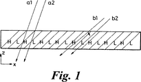
図1は、極端に簡略化された感光性ポリマーの断面ブロック図であり、感光性ポリマーの異なる屈折率を有する光の相互的干渉の可能性を図示するために提供されるものである。これについては、以下の詳細な説明の背景部分に記載する。
図2は、本願発明に記載の装置の製造方法のフローチャートである。
図3は、該方法を図示する略斜視図である。
図4Aおよび図4Bは、該方法を図示する平面ブロック図である。
図5は、本願発明に記載の装置を図示する断面ブロック図である。
好適な実施例の詳細な説明
わかりやすくするために、レーザおよびホログラムの簡単な背景と間連する用後について述べる。
「レーザ」という用語は、Light Amplification by Stimulated Emission of Radiationの略語である。レーザ光源を生成するにあたって、媒体は、類似する原子の分布を固体または気体の透過浮遊(suspension)中に含み、通常、加熱または励起(excite)されて大部分の原子を励起状態で生成する。このとき電子は、原子の「ground」の外側の高位の軌道または非励起(unexcited)状態にある。光のビームを媒体に導入すると、光量子を励起原子から吸収および再放出する。原子は励起(excitation)の臨界状態にあるため、光量子を導入すると、原子は、同一の波長と位相を有する第二の光量子とともに入射光量子を吸収および再放出する。このプロセスにより、「カスケード(cascade)」は、新たに放出された各光量子が他の原子を刺激してこれを吸収および放出することによって光を増幅する。理想的状況では、このようにして上述のシステムによって得られた光はコヒーレントであるため、すべての光は同一位相であり単光である。この場合、光は単一の波長からなる。しかしながら、実地では(in practice)、原子の励起は完全ではなく、いくつかの異なるエネルギーの状態が浮遊で原子間で誘発される。これにより、光の細長いスペクトルが起こるが、これは、一時的に間隔のあいたリズムにおいて頻繁に見られ、このリズムを「モードホッピング(mode hopping)」と呼ぶ。大部分の光量子が1つの波長から次の波長へ変位する。様々な理由により、その誘発された媒体の屈折率は、しばしば不定常であり、熱励起(thermal excitation)によって、位相は時間を浮遊する傾向にある。このような浮遊時間を光速で割り、これによってレーザビームのコヒーレント長が定められる。これは、数ミクロンから何メートルにも変化するが、レーザのタイプによる。
ホログラムおよびその製造方法は、先行技術において周知である。ホログラムは、本質的に回折格子である。感光性ポリマー(photopolymer)を角度Aを有する基準ビーム(reference beam)および角度Bを有する入射ビームに照射すると、回折格子が生じる。光が通過することによって特定の角度で生じた回折格子は、相互に干渉し合う(mutually interactive)3次元格子として形成され、この格子は、再生ビームの特定の入射角でのみ所望の縞模様(fringe pattern)を表す。光は、ホログラムを再生ビームまたは基準ビームと同じ角度で入射し、回折格子の示差屈折率と相互に干渉し合い、新たな波長依存性角(wavelength dependent angle)で回折される。その他の角度は、回折格子の示差屈折率を損なう(miss)傾向があり、その代わり、実際にホログラムがすべて単一の平均屈折率であるようにホログラムの屈折率の総和(sum)と影響し合う。図1は、効果を表す。なお、光路s1およびs2は、ほぼ等量の低(L)屈折率および高(H)屈折率を通過し、一方、任意の臨界角度において光路b1およびb2は示差屈折率を通過する。
感光性ポリマーのホログラム効率(efficiency)を測定する場合、入射光および非干渉(non-interacted)光とホログラム光素子の所望の目的(intended)方向に回折が伝達する光とを比較する。光の回折は、回折格子がどの程度まで存在(present)するかに応じて行われる。回折格子が存在する程度は、ホログラムの感光性ポリマーをどの程度まで重合および架橋可能であるかによる。感光性ポリマーの重合および架橋が行われるのは、感光性ポリマーが回折格子の生成に使用される光源に照射されるとき、およびさらに紫外放射および熱硬化に照射されている間である。重合および架橋の程度を調節することによって、回折格子が存在する程度およびそれによってホログラム効率を調節可能である。ホログラムはハロゲン化銀等金属ベース(metal-based)の乳剤から作られ、その効率は、乳剤の粒子サイズを変えることによって可変となる。
ホログラム効率の現象を上述の装置によって利用して、位相消去する(phase cancelling)光路を強制的にとる光の割合を修正することができる。これは、示差屈折率を通過する光によってのみ干渉縞が生じ、これによって回折光路が生じるからである、実地では、ホログラムのHおよびL部分は、重合が不完全であるため十分に定められないので、上述の重合において説明したように、ホログラム効率は、理想的な角度であっても低下する。
また、本願発明を十分に理解するための基本原則として、屈折現象および屈折特性がある。光線は異なる屈折率を有する2つの光学媒体を通過し、光線は光学媒体の境界面(interface)に直交する(通常)角度以外の任意の角度であるため、角度を変更することができ、低い屈折率から高い屈折率に変化する場合には鋭角に、そして高い屈折率から低い屈折率に変化する場合には傾斜角になる。この現象を容易に理解するためには、媒体の屈折率が高ければ高いほど光はその媒体をゆっくりと通過することを思い起こせばよい。したがって、光線がより高い屈折率を有する媒体に傾いて入射すると、光線は減速して進行し、これにより減速側に向かって屈折する。屈折の角度は、2つの光学的媒体の屈折率および入射光ビームの波長における違いによる。
光のビームが進行する媒体の屈折率と比して異なる屈折率を有する干渉性光学材料(intervining optical material)を通過する場合(例として、窓通過光)、屈折率の変化は、干渉性光学材料に入射するときと流出するときとで、等しくなり反対になり、たとえば、ビームが干渉性光学材料に入るとビームは一方向に屈折する、またビームが干渉性光学材料を出るとビームは反対方向に逆に等光量屈折する。したがって、入射ビームおよび出射ビームは平行となる。しかしながら、ビームが干渉性光学材料を流出する点はビームが流出した点と比べて横にシフトすることになり、元の入射ビームは非屈折干渉性光学材料に直行していた。横方向への変位量は、干渉性光学材料内での扇形変位および入射ビームと出射ビームとのずれによる。
本願発明において、第二ホログラム効率は、できるだけ100%に接近するように設定され、第一ホログラム効率は第二ホログラム効率の半分すなわち50%に接近するように設定される、所定の入射角度の光のコヒーレントビームが第一ホログラムに入射する場合、ほぼ50%のビームが第一ホログラムを通過し、屈折率の変化のみに影響し、ほぼ50%のビームが回折される。両ビームが干渉性光学材料に入射すると、これらは屈折率において別の変化が生じる。これによって各ビームの角度の波長依存性変位を誘発する。干渉性光学材料の屈折率が選択されると、屈折角度における波長依存性変位を誘発し、この角度は、第一ホログラムによって誘発された回折角度における波長依存性変位と等しくかつ対向する。したがって、角度は、回折されたビームの波長ごとに相互に消去し合う。したがって、回折されたビームの扇形光路は、干渉性光学材料を通過して、第一ホログラムの出射の扇形光路と本質的に対向する。
回折されたビームが干渉性光学材料を出て、第二ホログラムに入ると、屈折率の変位は、回折されたビームが第一ホログラムに残り干渉性光学材料に入射するにつれて発生する屈折率の変化と等しく対向する。これは、2つのホログラムの平均屈折率が等しいことから当然である。したがって、回折されたビームは第二ホログラムによって屈折されるが、この場合、第二ホログラムから出発する第二ホログラムの角度が第一ホログラム(回折の元の角度)から出発する第一ホログラムの角度と平行である。なお、回折されたビームは、第二ホログラムの回折格子について精確な入射角度をなさず、第二ホログラムを通過することに留意すべきである。この場合、第二ホログラムは、屈折率の変化によってのみ影響を受ける。
回折されないビームは、第一ホログラムを出て、第一ホログラムおよび干渉性光学材料をともに通過して第二ホログラムに入るが、この第二ホログラムは、屈折率の変化によってのみ影響を受ける。したがって、回折されないビームは、干渉性光学材料を出て、第二ホログラムの回折格子に入射するが、その際第一ホログラムに入射するときにとった光路に対して横向きまたは平行に変位する光路をとる。したがって、回折されないビームは、精確な入射角度を有して第二ホログラムの回折格子の示差(differential)屈折率と相互に干渉し合う。第二ホログラムは、100%有効に近いため、ほぼすべての回折されなかったビームは回折されない。したがって、第二ホログラムを下の回折されたビームと平行に流出する。
第二ホログラムがわずかに移動することによって、2つの出射ビームがそのビームの径の大部分を重ねるようにしてもよく、元の回折されないビームが、第二ホログラムによって遮られてもよい。この場合、ビームがとる光路は、元の回折ビームがとった光路と2分の1波長の整数倍分異なる。これによって得られた結合ビームは、すべての波長および位相について少なくとも1%プラスマイナスの帯域幅にわたって消去される。
第一および第二ホログラムは、後述するような構成である。一連の操作について、図2のフローチャートにまとめる。
第一ホログラムの回折格子を生成するにあたって、ホログラム板またはホログラム膜を角度Aの基準ビームおよび角度Bの入射ビームに照射する。従来のプルとタイプの発明において、アルゴンイオンレーザを光源として使用するが、様々なレーザを使用しているホログラフ膜の特性に対して使用してもよい。
レーザを光学実験ベンチおよびビームスプリッタに取付けて、ミラーを使用してレーザビームを分割して、基準ビームおよび入射ビームが適正角度を有するようにホログラム板に投影する。プロトタイプの場合、基準ビームの角度はホログラムに対して垂直状態からほぼ30度であり、入射ビームの角度は垂直状態からほぼ2−3度であった。これらの角度は、どちらのビームもホログラムに対して正確に垂直でない限り可変であり、または、ホログラム面とほぼ水平に近いのでビームはホログラムと相互に干渉し合うことなく回折格子を形成する。
第一ホログラム効率は、好ましくは50%近くに感光性ポリマーの照射を調整することによって設定され、その効率によって、またはハロゲン化銀ホログラムの場合には達成可能なその半分とのコントラストを減少させることによって重合を制限する。出射ビームと入射ビームとの輝度差を光センサを用いて測定することによって、所望の効率を達成する点を決定できる。第二ホログラムの製造は、同一基準ビームおよび入射ビームを同一角度で使用することによって行われる。ただし、効率を実用と同じほぼ100%にする、またはハロゲン化銀ホログラムを用いて達成可能な限界までにする。近年の感光性ポリマーは、一連の反復照射試験(iterative exposure test)および熱硬化試験を実施する場合、典型的には、最大97%の効率が可能であるる。経験から、定常照射および焼付けを任意の感光性ポリマーに対して任意の製造者によってバッチ式に、数回反復の後に任意の選択された重合効率について決定することができ、これによって任意の選択されたホログラム回折効率を決定することができることが明らかである。
感光性ポリマーを安定して製造することはまだ架空のことではないため、こrによって得られるホログラムの回折比と屈折比を算出することは不可能であり、このため特定の屈折率を干渉性光学材料に対して予め決定することは、現在のところ、不可能である。上記の課題の解決策は、感光性ポリマーの熱硬化特性を利用することである。これについて後述する。
図3および図4Aを参照して、一対のレーザは波長差が数ナノメートルであり、このレーザを設定してビーム10および12をビームスプリッタ14に供する。これにより、炉(図示せず)を通して単一共線混合ビーム16を生成して、スクリーンまたは、好ましくはセンサアレイ18に投影する。ホログラム2は、100%有効であり、これをビーム16の光路にX点にビーム16がホログラム2を基準角αで当たるように配置する。入射ビーム16は、本質的に2つの異なる光の波長からなり、所定のホログラムの回折角度は波長依存性である。したがって、2つの出射ビーム(20および22)はホログラム2によって生成される。1つのビームにおける光の波長は、他方のビームにおける光の波長より短く、2つのビームはともにセンサアレイ18に2つの投影点24および26として投影される。2つの投影点24の中心と26の中心との差異は、光センサアレイによってY点で測定され記録される。
ホログラム2は、X点で除去されテスト感光性ポリマー28(図4B)と置き換えられる。このテスト感光性ポリマーは、ホログラム1がコヒーレントな光に照射されたものに等しい総ジュール熱に照射される。この場合、テスト感光性ポリマー28の平均屈折率は、ホログラム1の平均屈折率と等しい。干渉性光学材料は、硬化処理されていない感光性ポリマー30として、テスト感光性ポリマー28とセンサアレイ18との間に配置される。ホログラム2またはテスト感光性ポリマー28の屈折率と干渉性光学材料30の屈折率の差分によって、所定の波長について第一ホログラム1と干渉性光学材料30との間の境界面において屈折角度を規定する(図5における境界面32)。また、この角度が波長依存性であることによって、このセットアップが規定されるように設計される。
干渉性光学材料30の屈折率は感光性ポリマーの構造および密度によって決定され、感光性ポリマーを使用して干渉性光学材料30を作成する。この感光性ポリマーの構造および密度は可変であり、感光性ポリマーおよびその活性化するダイが照射される光量および照射することによって温度上昇を誘発する次の架橋に対する光量による。感光性ポリマーを照射して適当な光量を得ることによって、および温度上昇による硬化(架橋)が行われる間に屈折率をモニタすることによって、特定の屈折率が達成できる。
実際の屈折率は、ゆっくりと時間と温度に比例して変化する。特定の値では温度が臨界温度を下回ることによって凍結することもある。この臨界温度において、架橋が所定の感光性ポリマーについて生じる。上述のプロセスが達成困難であるのは、屈折率が一方向でのみ変化することによること、および硬化プロセスが瞬間的に停止できないことによる。しかしながら、実験では、温度が硬化点未満に低下後、サンプルとして同一の感光性ポリマーを用いて、および角度の変化を注意深く観察することによって、あらかじめ、硬化温度が臨界温度にどのくらいの所望の角度減少すべきであるかを容易に知り得る。感光性ポリマーの臨界温度は、完成素子(finished element)の最大作動温度を表すが、これは、温度上昇にさらに照射されたことにより、屈折率が上述の重合および架橋のプロセスによって予め確立されている所望の屈折率から変化する。
十分な屈折率の範囲を有するほぼあらゆる感光性ポリマーを使用して、干渉性光学材料を作成してもよく、ホログラムの生成のために用いられたものと同じ感光性ポリマーを含んでもよい。そのために必要となるものは、ホログラムの平均屈折率と異なる平均屈折率に対して干渉性光学材料が硬化可能である。また、この材料における光速がすべての方向において等速である場合、ホモトピックであることも必要である。低コストの感光性ポリマー、たとえばLoktite Corporation社製造の紫外放射硬化接着剤がこの目的において使用されてきた。感光性ポリマーを活性化させる一般的なダイもまた適正材料であり、いくつかの製造元から入手可能である。このテーマについて各種出版された論文において公式を決定することが可能である。
感光性ポリマーの初期屈折率は、干渉性光学材料30に用いられるべきものであり、ホログラム1の平均屈折率よりも大きいまたは小さいが、これは所望の方向における回折された出射ビームを屈折させるのに必要な屈折率の変化に基づく。重要なことは、初期屈折率は干渉性光学材料30について選択することであり、この場合、第一ホログラム1と干渉性光学材料30の間の屈折の変化によって、ホログラム1から出る出射ビームが干渉性光学材料を通過すると、出射ビームはその偏向光路と対抗して屈折し、ホログラム1の回折角度は周知であるため、常に多かれ少なかれ初期屈折率を有することが選択可能である。干渉性光学材料30のために使用されるべき感光性ポリマーは、通常、十分な紫外放射によって処理されており、この感光性ポリマーを上述のように初期屈折率を有する固体に変換する。
干渉性光学材料30の製造について以下に記載する。
再び図3および図4を参照して、ホログラム2をXの位置で除去してテスト感光性ポリマー28と置き換える。感光性ポリマーは、干渉性光学材料30のために使用され、この感光性ポリマーを長寸法(long dimension)Lと短寸法(narrow dimension)Mを備えるように用意する。寸法Lは、図3および図4において距離X−Yと等しくなるようにする。距離X−Yは、テスト感光性ポリマー28とセンサアレイ18とに等距離であり、ホログラム1とセンサアレイ18とに等距離である。プロトタイプにおいて、高さ6cm、幅0.3mmの感光性ポリマー6を用いて干渉性光学材料30を作製した。しかしながら、後述するように処理および構造への配慮は、寸法MおよびLの実寸について主要な基準となる。
感光性ポリマー30の一端は、センサアレイと接触して配置され、他端は、X点でテスト感光性ポリマー28と隣接して配置されている(図4B)。したがって感光性ポリマー30の寸法Lはセンサアレイ18に対して垂直になる。
一対のレーザを付勢すると、共線ビーム16が炉にテスト感光性ポリマー28および感光性ポリマー30を通して投影される。感光性ポリマー30の出射側では、2つのレーザのうち短い波長のものが長い波長のものに対して横向きに移動され、この場合、2つのビーム20と22は、感光性ポリマー30を出て、2つの投影点24および26としてセンサアレイ18に当たる(図4B)。感光性ポリマー30をアレイ18に対して直交するその長寸法Lと置き換えることによって、2つのビームの投影点の変位がYにおいて測定されるが、これは、寸法XYが感光性ポリマー30の作動寸法となる寸法Mと等しいとされる場合に比べてより容易に測定可能である。
初めに、紫外光を使用して感光性ポリマー30を硬化させる。感光性ポリマー30が硬化すると、2つのビーム20および22の投影点24、26の中心の差異における逐次的変化をセンサアレイ18において測定できる。初めに、投影点24、26が互いに接近する。硬化処理を開始すると、投影点24、26が拡散を開始する。投影点24、26の距離が所望の拡散に近づき始めると、紫外光は消えて、炉を感光性ポリマー製造業者の推奨する温度に設定して消す。上述の通り、硬化処理は瞬間的な停止が不可能である。したがって、炉を予めしっかり消して、硬化処理が最終的に終了するときに、投影点24、26の中心において距離を測定するが、この距離は、第一ホログラム1によって生成される投影点の中心で測定する距離と同じであり、これによって感光性ポリマー30の屈折率を確立する。
この点において、2つのビーム20、22の投影点24、26の線形変位がテスト感光性ポリマー28と感光性ポリマー30との間の屈折率の変化によって扇形に変位し、線形変位と等しくなる。線形変位は、ビーム20、22と等しいかつ対向する扇形変位によって生じ、このビーム20、22は、すでに測定されたようにホログラム1によって回折されている。したがって、完成した光学装置では、第一ホログラム1と干渉性光学材料30との屈折率の変化により、波長依存性変形は、屈折角において屈折材料30によって誘発され、第一ホログラム1によって誘発される回折角における波長依存性変形と等しくかつ対向する。この場合、角は、入射光学ビームの各波長について相互に消去される。
図5のアッセンブリについて、達成可能となった。
干渉性光学材料(感光性ポリマー30)を寸法Mによって2つのホログラム1および2の間に挿入する。ホログラム1は、50%有効であり、干渉性光学材料についてその拝礼が安定している。レーザビームBは、修正入射角を有し、ホログラムの回折格子の示差屈折率と相互に干渉し合い、安定化されたホログラム1において方向づけられることによって、図5における2つの出射ビームp1およびp2を光学装置において生成する。34はホログラム偏向を示す。両ビームは、様々な角度で干渉性光学材料30を出す。ビームp1は、回折ビームを表す。
UV硬化接着剤を光学材料30または第二ホログラム2のいずれかの照射面に少量塗布する。第二ホログラム2は干渉性光学材料30に対して増大するため、既存のビームの光軸を中心として枢動させたままビームp1およびp2は結霜ガラスまたはCCD等ターゲット上の単一の斑点として配列する。次に、第二ホログラム2が横向きに調節される。第二ホログラム2が横向きに(寸法Mに垂直に)移動すると、ビームが光と暗線の間で変調することがわかる。斑点をさらに深く調査すると、2つのビームp1およびp2がターゲット上の2つの環として重なっていることがわかる。このことは、レンズを用いてビーム投影点を拡大することによって(眼球保護については通常の用心を払いながら)またはCCDとモニタとを接続することによって容易に達成可能である。
所望の状況とは、ビームp1およびp2の最大の重なりと最大の消去とが同時に達成することである。ビームp2は、第二ホログラム2によって回折され、ビームp1に比べてわずかに縁の透過力が強い傾向にある。これによって、重なりをそろえることが容易になるが、これは、実地において、ビームp1がわずかのハロー(halo)または「コロナ(corona)」をビームp2の周りに形成することによる。ビームp2によって、ビームが理想的な配列を施されたときおよびいつ最大の消去(破壊的干渉)が達成されたときを容易に知ることが可能である。このような調整は可能であるが、ビームの径は波長に対して大きく、またホログラムを横向きに調節することによってビームp2のその部分がビームp1より2分の1波長の整数倍分長く光路をとることによって、遮断が可能だからである。2つのビーム光路の間で必要な示差は、結合されたビームの径の範囲内で何度も発生する。したがって、第二ホログラムは、最適位置が選択されるまで数回の破壊ピークについて調節可能である。
オペーレータが最適条件の達成に満足すると、装置は全体として紫外線に照射されて接着剤を硬化する。各種の製造業者が、このような接着剤を作成し、理想的な硬化照射が使用接着剤の製造業者によって推奨される。
数回のピーク相殺の差異は、ビームの重なりという点で小さいため、装置の全体的な性能は、装置がビームの重なりという点ではなはだしく調整不良であるとしても最適条件の1パーセントの数分の一だけ変化する。また、相殺点が完全でなくても、再生ビームの入射角度のわずかの調整によってある程度まで修正できる。最大効率にあたって、第二ホログラム2の位置決めは、注意深く行うべきである。たとえば、本装置を強力レーザシステムにおける空間フィルタの口径として用いることになっている場合、当然重要なことは、できるだけ少ない出力(power)で構成を素通り(bypass)するか、構成によって吸収されるかのいずれかである。
第二ホログラム2の調節は、顕微鏡レベルの調節に使用されるようなマイクロマニピュレータによって達成可能である。別法として、圧電変換器(piezoelectric transducer)を適正に構成されたジグの部品として使用することがある。圧電変換器は、寸法を電界に比例して変化させる。ホログラム1と2および干渉性光学材料30を、永久的にその位置にクランプによってUV硬化接着剤の代わりとして固定可能である。
ホログラム1と2および干渉性光学材料30との関係によって、ビームを一時的に完全に消去したままであるとき、入射波長を最大2%変化させることが可能である。実際の輝度の消去は、完全とはいえないが、これは、ホログラム重合またはハロゲン化合物のコントラスト効率が完全ではないからである。
本装置によって、入射光の広域帯域を消去可能となることを、以下図5を参照して説明する。
入射光の波長は、寸法dxを長い波長のときはdxを大きくなるように変化させる。したがって、p1の光路長およびp2の光路長は、波長依存性である。dxの平均値を定めることによって、光路p1および光路p2との差異をレーザの平均波長の2分の1波長の整数倍分として設定することが可能である。その倍数を奇数、すなわち1、3、5、7等とすると、ビームp1およびp2は、消去する。さらに、p1とp2の差分が波長依存性であるdxによって定義されるため、p2の遅延が一定して2分の1波長に光学装置と相互に干渉し合うdxがビームp1とp2の径を越えないような範囲内にあるいずれの波長においても等しく設定可能であることがわかる。dxの平均値を定義してレーザの平均波長の2分の1波長の整数倍分として光路p1と光路p2の差を設定することは、第二ホログラム2を上述の通りわずかに調節することによって容易に達成できる。第二ホログラム2の補正位置決めが確立されると、波長ごとの個々の遅延は、その波長と比例して行われる。
寸法Mが重要となるのは、dxとどのように関連しているか、およびp1とp2との平均光路長差を定義することについてのみである。dxは自由に調節可能であるため、処理および構造の考慮が寸法Mの実寸における主要な基準となる。上述の通り、寸法Lは、距離XYによって定義され、単純に選択されて投影点が光センサアレイ18によって確実に十分に区別可能である。したがって、本装置を説明しやすくするために寸法MおよびLという符号を付しているだけである。たとえば、達成可能な装置は、寸法Mを0.05mmを最小として、1mmを最大にする構造であった。CCD光センサアレイは、プロトタイプの構造において使用され、十分な解像度を有し、寸法Lを10mm未満にすることが可能だが、実地では、どんな市販のカメラタイプのCCDアレイをこの寸法Lで使用してもよい。
再生ビームの側面への移動はビーム径に対してわずかであることに留意すべきである。第二ホログラム2からの2つのビームは、数パーセントの波長の変形によって波長が移動するということから定常に干渉し合う。再生ビーム角が変化すると、ホログラムによるビームの相互的干渉も変化する。角度が大きくなると、より多くの光が格子を相互に干渉し合うことなく通過する。これは、示差屈折率は、格子を定義し、光がフィルムの間欠(index)を1以上通過することによってズレを生じさせるからである。これは図1において明確に示される。この間欠は、光線の光路を通して平均化される実際の原子密度によって定義されているので、この密度は非常に小さな範囲で変化する。この結果、ビームを消去する蓋然性(probablity)は、ホログラムのピーク効率が定義する完全に最大からほぼランダムな分布を有する最小へ変化する。非消去(non-cancelled)条件における出射ビームは、偏光されたままであるが、コヒーレンスは、初期レーザ入射ビームから減少する。コヒーレンス損は、ほとんど問題にならない。ただし200万波長を越える長い範囲の投影を必要とする場合はこの限りではない。100万波長以内であれば、焦点を結ぶことによって、回折限界の妥当な近似値において達成可能である。
また、留意すべきは、初期ホログラムは波を回折光路または回折されない光路(ホログラムの重合された部分を通過する特定の光量のランダムな偶然(chance)にのみ依存する)を通過させるので、遅延されたビームの相当部分が、別の光路をとるコヒーレントなパートナーを欠落させた光量子からなると予測されることである。実地では、光量子のいわゆる量子的絡み合い(entanglement)はレーザ光源から放出され、任意のレーザ光源について、これまで考えられていたよりもはるかに多くの量にわたって延在している。これによって、光量子が装置を通過して自ら対になる選択を行うという予期せぬ傾向が見られる。遅延された光路をとったものと、短い光路をとったものである。この効果がなければ、上述の装置における消去の予測レベルは70%の程度となる。実際に計測された相殺は、98%以上であることは頻繁に生じる。
効果は、ある種の吸収よりむしろ消去に真に見られる。この決定は、周知の出力を有するレーザビームを遮断するために使用される素子の温度を測定することによって容易に行われる。ビームの輝度が、吸収によって減少する場合、素子の温度は、遮断されたエネルギーに比例して上昇する。一方、消去の場合、温度上昇は予測されない。注意深く測定することによって、このような温度上昇が生じることがわかり、このことは、ビーム輝度において98%減少することが実際に消去のみによるものであることを表す。
上述した光量子の絡み合いについて、室温での実験における実用的な最大消去は、ほぼ98%であることが知られてきた。このことは、調整された温度の適用範囲を向上させ、環境温度が10℃以上変化しなければならない場合には減少し得る。本装置によって、500mW以上の出力密度で安定させておくことが可能となり、観察された効果が正確な共線消去であることを証明する(効果が一部誤解を招く吸収の現象によるものである場合、出力は吸収され素子は上述のように溶解する)。
本光学装置は、ここで記載するように、純粋な実用的用途を供するものであり、高出力のレーザのための減衰器(attenuator)としての機能を奏す。単にシャッタに高出力のレーザビームを通すことはできない。ビームは単に噴射するだけであるからである。上述の装置は任意の出力のレーザビームを遮断し、その輝度を98%減少し、それ自体エネルギーを吸収しない。実用的な実験では、500mWのビームを用いて行われた。ビームの出力密度は、312W/cm2であり、温度変化は入射出力のわずか0.1パーセントと同等であった。
光学装置の別の簡単な用途は、空間フィルタの生成である。従来の空間フィルタは、ピンホールからなり、このピンホールを通して、レーザが投影される。ホールの円周は、レーザビームの全出力を受けるので、ホールは、短時間に噴射(burnacross)する傾向にある。この課題を克服するために、上述の発明に記載の光学装置は、特定のレーザおよびそれに穿孔されたピンホールについて達成可能である。レーザビームが、従来のピンホールのようにホールの縁で放射を吸収するよりむしろピンホールにおいて方向づけられ、すべての光は、ピンホールを通過できず単に消去される。
また、本願発明の光学装置によって、無色光学レンズ構造が可能になり、この場合、レンズはホログラムの回折格子と、屈折素子とを含む本願明細書に開示されるような相互関係にある。実地において、単一のホログラム/屈折レンズでは、光学スペクトル全体を網羅できない。しかしながら、このような群の装置であれば、工学スペクトル全体を網羅できる。感光性ポリマーを前述のように使用することは、現在のところ本願発明を実施する好適な方法ではないが、これは、その他の方法で行ってもよい。
撮像タイプの金属ベースの乳剤、たとえばハロゲン化銀を使用してホログラムを構成してもよい。しかしながら、光学装置の効率は、ハロゲン化銀のホログラムを利用するとかなり減退し、感光性ポリマーのホログラムおよび低出力のレーザを利用して実現されるものと同じ優れた結果を達成するためにははるかに強力なレーザが必要となる。乳剤を感光性ポリマーと共同して使用してホログラム効率を設定する際に乳剤の粒子サイズを調整してもよい。または、ホログラム素子を形成する際に乳剤層の写真の露光または撮像マスターから生成された圧力素子を用いてもよい。
本願発明において、上述のように一対のホログラム回折格子の使用について記載してきた。原則的に、本願発明の利益を選択された屈折率の中間部材によって分割された様々なタイプの回折格子(またはその他光学的散乱element)を用いて達成することが可能である。
また、変形させることによって上述の実施形態を本願発明の範囲内において達成してもよい。 Field of Invention
The present invention relates to an optical device that generates non-fringing destructive interference of light and a method for manufacturing and using the same.
Background art
Light travels in space as electromagnetic waves. The electromagnetic wave is considered to continuously move at a predetermined frequency along a predetermined optical path as a series of peaks and troughs. Interference occurs when two waves pass through the same region simultaneously. Interference in the waves is constructive and destructive. Constructive interference occurs when two wave peaks (or troughs) meet and overlap at the same time. These waves are in phase, and when generated, the amplitude of the waves at the overlapping points is said to increase.
Destructive interference occurs when one lightwave peak meets and overlaps a second lightwave trough. When the peak and trough meet each other, they cancel each other, so the light wave is said to be phase canceled. A completely phase erased wave has no electromagnetic energy.
Both structural interference and destructive interference due to light are revealed by a double split experiment, where light from one light source falls onto a screen containing two adjacent slits. If the viewing screen is placed behind the first screen, a series of light and dark lines will appear on the viewing screen. This series of lines is referred to as an interference pattern.
The bright line of the interference fringes is the area of structural interference, and the dark line is the area of destructive interference. The generation of the fringes is performed when a wave having an arbitrary wavelength enters the two slits. The waves spread in all directions after passing through the slit and interfere with each other. If waves reach the center of the autopsy clean from each slit and the waves travel equidistant and hit the screen, they are in phase and a bright spot representing structural interference appears at the center of the autopsy screen. Also, structural interference occurs at each point where the optical paths of the two rays differ by one wavelength or by an integral multiple of one wavelength. However, if a ray travels an extra distance of half a wavelength or an integral multiple of a half wavelength, the two waves are just out of phase when they reach the screen, A dark band appears in the fringes representing destructive interference. A series of bright and dark lines is thus obtained in the interference fringes, which is called “fringe”.
The double slit experiment is one way to generate destructive interference. However, only a small part of the light source is canceled. Another method of generating destructive interference of light has been achieved using beam splitters, mirrors and lasers. This type of device is often referred to as an interferometer.
The interferometer operates on the following basic principles. A laser is used in conjunction with a beam splitter to split the laser beam into two, taking one optical path at an arbitrary ratio of light and another at an arbitrary ratio of light. One optical path of the split beam can be delayed by using a movable mirror, in which case the beam can be reflected parallel to the unreflected beam by a variable optical path length. This optical path length varies depending on the refraction of the wavelength. The degree of erasure depends on the “coherence length” of the lens and the narrowness of the chromatic line. For this reason, an extremely high quality laser must be highly erased. However, the laser does not produce pure monochromatic light and the fringes are produced regardless of the degree of erasure. To generate a fully phase-cancelled collinear beam, destructive interference occurs over the entire bandwidth of the incident light source at all incident wavelengths and phases. Also, all the light rays emitted by the light source are parallel, and each photon in the beam is paired with another photon having exactly the same wavelength, and with respect to the optical path length of the partner of the paired photon, The optical path length of half of the photons is delayed by an integral multiple of one-half wavelength.
Such a result cannot be achieved with the conventional configuration. A pair of semi-silver mirrors can be arranged so that one specific wavelength can be interfered with, but it is impossible to correct all wavelengths. By using a refractive element, the delay can be adjusted. However, since this only affects non-zero incident angles, as a result, each wavelength continues to travel along a non-parallel optical path. Since the angle of this optical path can only be increased by the mirror, the beam cannot form a collinear beam, so individual photons are not paired.
Accordingly, it is an object of the present invention to provide a very efficient optical device, and the output beam produced by this optical device is non-striped collinear and phase canceling. In this case, (a) destructive interference occurs over a bandwidth of at least 1% plus or minus the central wavelength of a coherent light source such as a laser for all incident wavelengths and phases, and (b) the rays of all outgoing beams are parallel. (C) Each photon in the outgoing beam is paired with another photon having exactly the same wavelength, and (d) half the optical path of the photon with respect to the optical path length of the partner of each paired photon The length is precisely delayed by an integral multiple of one-half wavelength.
Summary of the Invention
The present invention achieves the above object and other objects by the method described below.
The optical device consists of a holographic element (“hologram”) and a refractive optical material having a particularly selected refractive index. A hologram is constituted by a diffraction grating, which induces a wavelength-dependent angle of diffraction for an incident optical beam of a predetermined incident angle. An assembly of hologram and refractive optical material can be applied to the angle of the optical beam so that the wavelength dependent deformation of the refraction angle is induced by the refractive material and is equal and opposite to the wavelength dependent deformation of the diffraction angle induced by the hologram. Erase each other at each wavelength.
In another embodiment, as already described, the optical device is a combination of a second hologram, the optical device consisting of two holograms and a coherent (refractive) optical material. The two holograms are both constituted by similar diffraction gratings and induce the same diffraction wavelength-dependent angle for an incident optical beam of a given incident angle. Both holograms have the same average refractive index. However, each hologram has a predetermined efficiency, which is different from another hologram efficiency. The first hologram is preferably about 50% effective or half as effective as the second hologram, and the second hologram is preferably close to 100% effective.
The first hologram is positioned parallel and spaced apart from the second hologram by the coherent optical material. The coherent optical material is essentially sandwiched between two holograms. The coherent optical material specifically selects a refractive index, which is different from the average refractive index of the hologram. The refraction angle is induced by the coherent optical material, and the refraction angle is also wavelength dependent.
By establishing an arbitrary refractive index for the coherent optical material, a wavelength-dependent deformation of the refraction angle is induced by the coherent optical material, and is equal to the wavelength-dependent deformation of the diffraction angle induced by the first hologram and In this case, the angles are erased from each other for each wavelength of the incident optical beam having a predetermined angle of incidence for the first hologram of the optical device.
Since the first hologram is 50% effectively close, approximately 50% of the incident optical beam passes through the undiffracted hologram, and approximately 50% of the beam is diffracted so that the first hologram produces two beams. The beams both sweep the coherent optical material and strike the second hologram at different angles. The diffracted beam passes through the second hologram, which is only affected by changes in the refractive index. On the other hand, the undiffracted beam influences the diffraction grating of the second hologram and is diffracted with an inclination so that the two beams exit the second hologram, both of which are parallel to each other.
By slightly adjusting the second hologram, the two outgoing beams overlap and the originally undiffracted beam can be blocked by the second hologram, but in this case, it is a half different from the optical path of the originally undiffracted beam. Take multiple wavelength spectral path. The combined beam is phase canceled over a bandwidth having a central wavelength of at least 1% plus or minus the incident optical beam for all incident wavelengths and phases.
Both the overall delay of the diffracted beam and the overall diffraction efficiency of the hologram can be adjusted by simply changing the angle of incidence in the first hologram. When the incident angle changes, the ratio of incident light is somewhat reduced and erased. The fundamental difference between this effect and the effect of simply fixing the delay for one of the beams is that a larger percentage of incident light passes through a defined optical path when the angles of the total elements are ideally arranged. It is to be. All light passing through the defined optical path is completely erased. Thus, a series of fringes can be seen in a conventional interferometer, but as described in the present invention, a single fringe or beam is generated by the emission of the element and then takes a defined optical path. Is accompanied by erasure at a proportion proportional to the amount of incident beam.
Another aspect of the present invention includes a method for manufacturing the above-described optical device. In manufacturing the device, two lasers are used to produce a mixed beam having collinear light consisting essentially of two different wavelengths. The mixed beam is directed to one of the holograms at a predetermined angle of incidence such that the two diffracted beams exit the hologram at different angles and project onto the photosensor array at a distance L from the exit side of the hologram. The distance between the projection points of the two diffracted beams is measured in the array.
The coherent optical material has a major dimension equal to L and a selected initial refractive index, the major dimension of which is between the photosensor array and a test photosensitive polymer having the same average refractive index as the hologram. Positioned orthogonal to the polymer and array. The same mixed beam is directed so that two outgoing beams are projected onto the array by the coherent optical material in the test photosensitive polymer. The refractive index of the coherent optical material is then adjusted by polymerization. As the refractive index of the coherent optical material changes, the distance between the projection points of the refracted beam also changes. The polymerization with the coherent optical material stops at a point where the displacement between the projection points of the refracted beam is measured in the same way as the displacement between the projection points of the diffracted beam.
The coherent optical material is then fixed to the first hologram such that its short dimension is orthogonal to the hologram. The second hologram is twice the efficiency of the first hologram and is positioned on the coherent optical material surface facing the first hologram. The incident optical beam has the proper angle of incidence and is directed at the first hologram so that two outgoing beams are generated by the second hologram. The maximum erase position is achieved when the beams overlap with a slight rotation and lateral shift to adjust the second hologram.
The optical device described above overcomes the limitations associated with interferometers. In this case, the generation of the non-striped phase cancellation beam is performed over a bandwidth of 1% plus or minus the center wavelength of a coherent light source such as a laser for all incident wavelengths and phases. Furthermore, the apparatus disclosed herein represents a simple and reliable method of generating a phase-cancelling collinear beam. Generation is possible even if the quality and power of the source laser are relatively low and limit the coherent length. By manufacturing the above-described apparatus, not only can we begin to study the properties of phase-erased collinear beams at an affordable cost, but it will be the basis for generating such beams for other scientific and commercial applications.
Other objects, features, and advantages of the present invention will become clear by reading the specification with the attached drawings.
[Brief description of the drawings]
FIG. 1 is a cross-sectional block diagram of an extremely simplified photosensitive polymer, provided to illustrate the possibility of mutual interference of light having different refractive indices of the photosensitive polymer. This is described in the background section of the detailed description below.
FIG. 2 is a flowchart of a method for manufacturing the device according to the present invention.
FIG. 3 is a schematic perspective view illustrating the method.
4A and 4B are plan block diagrams illustrating the method.
FIG. 5 is a cross-sectional block diagram illustrating an apparatus according to the present invention.
Detailed Description of the Preferred Embodiment
For the sake of clarity, the post-working associated with a simple background of lasers and holograms is described.
The term “laser” is an abbreviation for Light Amplification by Stimulated Emission of Radiation. In generating a laser light source, the medium includes a similar distribution of atoms in a solid or gas suspension, and is usually heated or excited to generate most atoms in an excited state. At this time, the electrons are in a high orbital or unexcited state outside the “ground” of the atom. When a beam of light is introduced into the medium, photons are absorbed and re-emitted from the excited atoms. Since atoms are in the critical state of excitation, when photons are introduced, the atoms absorb and re-emit incident photons with a second photon having the same wavelength and phase. By this process, a “cascade” amplifies light by each newly emitted photon stimulating other atoms to absorb and emit them. In an ideal situation, the light thus obtained by the system described above is coherent, so that all the light is in phase and single light. In this case, the light consists of a single wavelength. However, in practice, the excitation of atoms is not perfect and several different energy states are floated and induced between atoms. This results in an elongated spectrum of light, which is frequently seen in temporarily spaced rhythms, and this rhythm is referred to as “mode hopping”. Most photons shift from one wavelength to the next. For various reasons, the induced refractive index of the medium is often unsteady, and due to thermal excitation, the phase tends to float in time. Such a floating time is divided by the speed of light, thereby determining the coherent length of the laser beam. This varies from a few microns to many meters, but depends on the type of laser.
Holograms and their manufacturing methods are well known in the prior art. A hologram is essentially a diffraction grating. Irradiation of a photopolymer with a reference beam having an angle A and an incident beam having an angle B results in a diffraction grating. Diffraction gratings generated at a specific angle by the passage of light are formed as three-dimensional gratings that are mutually interactive, and this grating has a desired striped pattern (only at a specific incident angle of the reproduction beam). fringe pattern). The light is incident on the hologram at the same angle as the reproduction beam or the reference beam, interferes with the differential refractive index of the diffraction grating, and is diffracted at a new wavelength dependent angle. Other angles tend to miss the differential refractive index of the diffraction grating, and instead affect the sum of the refractive indices of the holograms so that all the holograms are actually a single average refractive index. Fit. FIG. 1 illustrates the effect. It should be noted that optical paths s1 and s2 pass approximately equal amounts of low (L) and high (H) refractive indices, while optical paths b1 and b2 pass through the differential refractive index at any critical angle.
When measuring the hologram efficiency of a photosensitive polymer, the incident light and non-interacted light are compared with the light transmitted by diffraction in the desired intended direction of the hologram optical element. The light is diffracted depending on how much the diffraction grating is present. The degree to which the diffraction grating is present depends on the degree to which the photosensitive polymer of the hologram can be polymerized and crosslinked. Polymerization and crosslinking of the photosensitive polymer occurs when the photosensitive polymer is irradiated to the light source used to generate the diffraction grating and while it is further irradiated to ultraviolet radiation and thermal curing. By adjusting the degree of polymerization and crosslinking, the degree to which a diffraction grating is present and thereby the hologram efficiency can be adjusted. Holograms are made from metal-based emulsions such as silver halide, the efficiency of which can be varied by changing the grain size of the emulsion.
The phenomenon of hologram efficiency can be used by the above-described apparatus to correct the proportion of light that forcibly takes an optical path that is phase cancelling. This is because interference fringes are generated only by light passing through the differential refractive index, and this causes a diffractive optical path. In practice, the H and L portions of the hologram are not sufficiently defined due to incomplete polymerization. Therefore, as explained in the above-described polymerization, the hologram efficiency is lowered even at an ideal angle.
Further, as a basic principle for fully understanding the present invention, there are a refraction phenomenon and a refraction characteristic. The ray can pass through two optical media with different refractive indices, and the ray can be any angle other than the (normal) angle orthogonal to the interface of the optical media, so the angle can be changed and low When changing from a refractive index to a high refractive index, it becomes an acute angle, and when changing from a high refractive index to a low refractive index, it becomes an inclination angle. To easily understand this phenomenon, recall that the higher the refractive index of the medium, the slower the light will pass through the medium. Therefore, when the light beam is incident on a medium having a higher refractive index, the light beam travels at a reduced speed, and is refracted toward the deceleration side. The angle of refraction is due to differences in the refractive index of the two optical media and the wavelength of the incident light beam.
When the light beam passes through an interfering optical material that has a refractive index that differs from the refractive index of the medium in which it travels (eg, light passing through a window), the change in the refractive index is Equal and opposite when entering and leaving the material, for example, when the beam enters the coherent optical material, the beam is refracted in one direction, and when the beam exits the coherent optical material, the beam is opposite Refracts the same amount of light in the opposite direction. Therefore, the incident beam and the outgoing beam are parallel. However, the point at which the beam exits the coherent optical material will shift laterally compared to the point at which the beam exits, and the original incident beam has gone directly to the non-refractive interference optical material. The amount of displacement in the lateral direction is due to the sector displacement in the coherent optical material and the deviation between the incident beam and the outgoing beam.
In the present invention, the second hologram efficiency is set to be as close to 100% as possible, and the first hologram efficiency is set to be close to half of the second hologram efficiency, that is, 50%. When the coherent beam is incident on the first hologram, approximately 50% of the beam passes through the first hologram, affecting only the change in refractive index, and approximately 50% of the beam is diffracted. When both beams are incident on the coherent optical material, they undergo another change in refractive index. This induces a wavelength dependent displacement of the angle of each beam. When the refractive index of the coherent optical material is selected, it induces a wavelength dependent displacement in the refraction angle, which is equal and opposite to the wavelength dependent displacement in the diffraction angle induced by the first hologram. Thus, the angles cancel each other out for each wavelength of the diffracted beam. Thus, the fan beam path of the diffracted beam passes through the coherent optical material and essentially opposes the fan beam path of the exit of the first hologram.
When the diffracted beam exits the coherent optical material and enters the second hologram, the refractive index displacement causes the refractive index change to occur as the diffracted beam remains in the first hologram and enters the coherent optical material. Is equally opposed. This is natural because the average refractive index of the two holograms is equal. Thus, the diffracted beam is refracted by the second hologram, in which case the angle of the second hologram starting from the second hologram is equal to the angle of the first hologram starting from the first hologram (original angle of diffraction). Parallel. It should be noted that the diffracted beam passes through the second hologram without making an accurate angle of incidence with respect to the diffraction grating of the second hologram. In this case, the second hologram is only affected by a change in refractive index.
The undiffracted beam exits the first hologram and passes through both the first hologram and the coherent optical material into the second hologram, which is only affected by the change in refractive index. Therefore, the undiffracted beam exits the coherent optical material and enters the diffraction grating of the second hologram, but in this case, the optical path displaced laterally or parallel to the optical path taken when entering the first hologram. Take. Thus, the undiffracted beam interacts with the differential refractive index of the diffraction grating of the second hologram with a precise angle of incidence. Since the second hologram is nearly 100% effective, almost all undiffracted beams are not diffracted. Thus, the second hologram flows out parallel to the lower diffracted beam.
A slight movement of the second hologram may cause the two outgoing beams to overlap most of their diameter, and the original undiffracted beam may be blocked by the second hologram. In this case, the optical path taken by the beam differs from the optical path taken by the original diffracted beam by an integral multiple of one-half wavelength. The resulting combined beam is erased over at least 1% plus or minus bandwidth for all wavelengths and phases.
The first and second holograms are configured as described later. A series of operations are summarized in the flowchart of FIG.
In generating the diffraction grating of the first hologram, the hologram plate or the hologram film is irradiated to the reference beam of angle A and the incident beam of angle B. In the conventional pull and type invention, an argon ion laser is used as the light source, but may be used for the characteristics of holographic films using various lasers.
The laser is mounted on an optical lab bench and beam splitter, and a mirror is used to split the laser beam and project it onto the hologram plate so that the reference and incident beams have the proper angles. In the case of the prototype, the angle of the reference beam was approximately 30 degrees from the perpendicular state with respect to the hologram, and the angle of the incident beam was approximately 2-3 degrees from the perpendicular state. These angles are variable as long as neither beam is exactly perpendicular to the hologram, or the beams form a diffraction grating without interfering with the hologram because they are nearly horizontal with the hologram surface.
The first hologram efficiency is preferably set by adjusting the exposure of the photosensitive polymer to close to 50%, reducing the contrast with that efficiency or in the case of silver halide holograms with half that achievable. To limit the polymerization. By measuring the luminance difference between the outgoing beam and the incoming beam using an optical sensor, the point at which the desired efficiency is achieved can be determined. The production of the second hologram is performed by using the same reference beam and the incident beam at the same angle. However, the efficiency is almost 100%, as practical, or to the limit achievable using silver halide holograms. Modern photosensitive polymers are typically capable of efficiencies of up to 97% when performing a series of iterative exposure tests and thermal cure tests. From experience, steady-state irradiation and baking can be determined for any photosensitive polymer batchwise by any manufacturer, after several iterations, for any selected polymerization efficiency, and thus any chosen It is clear that the hologram diffraction efficiency can be determined.
Since it is not yet fictitious to produce a photosensitive polymer stably, it is impossible to calculate the diffraction and refraction ratios of the holograms obtained by this method, so that the specific refractive index can be made coherent. Predetermining for optical materials is currently impossible. The solution to the above problem is to take advantage of the thermosetting properties of the photosensitive polymer. This will be described later.
Referring to FIGS. 3 and 4A, the pair of lasers has a wavelength difference of a few nanometers, and this laser is set to provide
The refractive index of the coherent
The actual refractive index changes slowly in proportion to time and temperature. At certain values, it may freeze when the temperature falls below the critical temperature. At this critical temperature, crosslinking occurs for a given photosensitive polymer. The above process is difficult to achieve because the refractive index changes only in one direction and the curing process cannot be stopped instantaneously. However, in experiments, after the temperature has dropped below the cure point, the desired angle reduction of the cure temperature to the critical temperature in advance using the same photosensitive polymer as the sample and carefully observing the change in angle You can easily know what to do. The critical temperature of the photosensitive polymer represents the maximum operating temperature of the finished element, which is pre-established by the polymerization and cross-linking processes described above by further exposure to the temperature increase. Varies from the desired refractive index.
Nearly any photosensitive polymer having a sufficient refractive index range may be used to make the coherent optical material and may include the same photosensitive polymer used for the generation of the hologram. What is needed for this is that the coherent optical material can be cured with an average refractive index different from the average refractive index of the hologram. Also, if the speed of light in this material is constant in all directions, it must be homotopic. Low cost photosensitive polymers such as ultraviolet radiation curable adhesives manufactured by Loktite Corporation have been used for this purpose. A typical die that activates the photosensitive polymer is also a suitable material and is available from several manufacturers. It is possible to determine the formula in various published articles on this subject.
The initial refractive index of the photosensitive polymer is to be used for the coherent
The production of the coherent
Referring to FIGS. 3 and 4 again, the
One end of the
When the pair of lasers is energized, the
First, the
At this point, the linear displacement of the projection points 24, 26 of the two
The assembly shown in FIG. 5 can be achieved.
An interfering optical material (photosensitive polymer 30) is inserted between the two
A small amount of UV curable adhesive is applied to the irradiated surface of either the
The desired situation is that maximum overlap and maximum erasure of beams p1 and p2 are achieved simultaneously. The beam p2 is diffracted by the
When the operator is satisfied with achieving the optimum conditions, the device as a whole is irradiated with ultraviolet light to cure the adhesive. Various manufacturers make such adhesives, and ideal curing radiation is recommended by the manufacturer of the adhesive used.
Since the difference between several peak cancellations is small in terms of beam overlap, the overall performance of the device is a fraction of one percent of optimal conditions, even if the device is significantly misaligned in terms of beam overlap. It changes by one. Even if the cancellation point is not perfect, it can be corrected to a certain extent by a slight adjustment of the incident angle of the reproduction beam. For maximum efficiency, the positioning of the
The adjustment of the
Due to the relationship between
The fact that the wide band of incident light can be erased by this apparatus will be described below with reference to FIG.
The wavelength of the incident light is changed so as to increase dx when the dimension dx is a long wavelength. Therefore, the optical path length of p1 and the optical path length of p2 are wavelength dependent. By determining the average value of dx, the difference between the optical path p1 and the optical path p2 can be set as an integral multiple of one-half wavelength of the average wavelength of the laser. If the multiple is an odd number, that is, 1, 3, 5, 7, etc., the beams p1 and p2 are erased. Furthermore, since the difference between p1 and p2 is defined by the wavelength-dependent dx, the delay of p2 is constant, and dx that mutually interferes with the optical device at a half wavelength has the diameters of the beams p1 and p2. It can be seen that the same setting is possible at any wavelength within a range that does not exceed. Defining the average value of dx and setting the difference between optical path p1 and optical path p2 as an integral multiple of one-half wavelength of the laser's average wavelength is achieved by adjusting the
The dimension M is important only for how it relates to dx and to define the average optical path length difference between p1 and p2. Since dx is freely adjustable, processing and structural considerations are the main criteria in the actual dimension M. As described above, the dimension L is defined by the distance XY and is simply selected to ensure that the projection points are sufficiently distinguishable by the
It should be noted that the movement of the reproduction beam to the side is small relative to the beam diameter. The two beams from the
It should also be noted that the initial hologram passes the wave through the diffracting or non-diffracting optical path (depending only on the random chance of a specific amount of light passing through the superposed part of the hologram), so it is delayed. It is expected that a substantial portion of the beam will consist of photons with missing coherent partners taking another optical path. In practice, the so-called quantum entanglement of photons is emitted from a laser source and extends for a much larger amount of any laser source than previously thought. This leads to the unexpected trend of photons passing through the device and making a choice to pair themselves. One with a delayed optical path and one with a short optical path. Without this effect, the predicted level of erasure in the above-mentioned apparatus is about 70%. The actual measured offset often occurs at 98% or more.
The effect is truly seen in elimination rather than some kind of absorption. This determination is easily made by measuring the temperature of the element used to block a laser beam having a known output. If the brightness of the beam decreases due to absorption, the temperature of the element increases in proportion to the energy that is interrupted. On the other hand, in the case of erasure, no temperature rise is predicted. Careful measurement shows that such a temperature increase occurs, which indicates that the 98% reduction in beam brightness is actually due to erasure alone.
It has been known that the practical maximum erasure in the experiment at room temperature is about 98% for the above-described photon entanglement. This can improve the scope of the regulated temperature and can be reduced if the ambient temperature has to change by 10 ° C. or more. This device makes it possible to stabilize at a power density of 500 mW or more, and proves that the observed effect is accurate collinear erasure (the effect is due in part to misleading absorption phenomena) The output is absorbed and the element dissolves as described above).
The optical device, as described herein, provides a pure practical application and serves as an attenuator for high power lasers. It is simply not possible to pass a high power laser beam through the shutter. This is because the beam simply jets. The device described above blocks any output laser beam, reduces its brightness by 98% and does not absorb energy itself. In practical experiments, a 500 mW beam was used. Beam power density is 312 W / cm2And the temperature change was equivalent to only 0.1 percent of the incident power.
Another simple application for optical devices is the generation of spatial filters. A conventional spatial filter includes a pinhole, through which a laser is projected. Since the circumference of the hole receives the full power of the laser beam, the hole tends to burnacross in a short time. To overcome this problem, the optical device described in the above-described invention can be achieved for a specific laser and a pinhole drilled therein. The laser beam is directed at the pinhole rather than absorbing radiation at the edge of the hole as in a conventional pinhole, and all light cannot pass through the pinhole and is simply erased.
Also, the optical device of the present invention enables a colorless optical lens structure, in which case the lenses are in the interrelationship as disclosed herein including a hologram diffraction grating and a refractive element. In practice, a single hologram / refractive lens cannot cover the entire optical spectrum. However, such a group of devices can cover the entire engineering spectrum. The use of a photosensitive polymer as described above is not currently the preferred method of practicing the present invention, but this may be done in other ways.
An imaging type metal-based emulsion, such as silver halide, may be used to construct the hologram. However, the efficiency of optical devices is significantly diminished with the use of silver halide holograms, and much more to achieve the same superior results achieved with photosensitive polymer holograms and low power lasers. Requires a powerful laser. The emulsion grain size may be adjusted when the emulsion is used in conjunction with a photosensitive polymer to set the hologram efficiency. Alternatively, a pressure element generated from exposure of a photograph of an emulsion layer or an imaging master may be used when forming a hologram element.
In the present invention, the use of a pair of hologram diffraction gratings has been described as described above. In principle, the benefits of the present invention can be achieved using various types of diffraction gratings (or other optical scattering elements) divided by an intermediate member of a selected refractive index.
Moreover, you may achieve the above-mentioned embodiment within the range of this invention by making it deform | transform.
Claims (13)
第1ホログラムと第2ホログラムを供給するステップと、
第1感光性ポリマーを供給するステップと、
前記第1感光性ポリマーの屈折率が所定の屈折率に達するまで重合することによって前記第1感光性ポリマーの屈折率を調節するステップと、
前記光学部品を形成するために前記第1ホログラムと前記第2ホログラムとの間に重合された第1感光性ポリマーを挿入するステップと、
を備え、
上記所定の屈折率は、2つの回折ビームがホログラムを異なる角度で送出するように、本質的に2つの異なる波長からなる共線光の混合ビームの範囲内で前記ホログラムの一方を位置決めすると共に、前記ホログラムの一方から予め決められた距離における前記2つの回折ビームの投影点の中心間の距離を測定することにより決定される、
光学部品の製造方法。An optical component manufacturing method comprising:
Providing a first hologram and a second hologram;
Providing a first photosensitive polymer;
Adjusting the refractive index of the first photosensitive polymer by polymerizing until the refractive index of the first photosensitive polymer reaches a predetermined refractive index;
Inserting a polymerized first photosensitive polymer between the first hologram and the second hologram to form the optical component;
Equipped with a,
The predetermined refractive index positions one of the holograms within a mixed beam of collinear light consisting essentially of two different wavelengths so that the two diffracted beams emit the hologram at different angles; Determined by measuring the distance between the centers of the projection points of the two diffracted beams at a predetermined distance from one of the holograms;
Manufacturing method of optical components.
前記第1ホログラムは前記第2ホログラムの半分の効率を有している、請求項1に記載の光学部品の製造方法。The first and second holograms have the same diffraction grating and the same refractive index, respectively.
The method of manufacturing an optical component according to claim 1, wherein the first hologram has half the efficiency of the second hologram.
a)前記1つのホログラムと、前記第1感光性ポリマーと、複数の前記ホログラムの平均屈折率を有する第2感光性ポリマーとを構成する機構を創造するステップと、
b)2つの屈折させられたビームと2つの対応した照射位置とを作り出すために前記機構を前記混合ビームにさらすステップと、
c)前記2つの屈折させられたビームの間の距離を変えるためにポリメリーゼーションによって前記第1感光性ポリマーの屈折率を変えるステップと、
d)前記屈折させられたビームの投影位置が前記2つの回折させられたビームの投影位置と同じ位置の時にポリメリーゼーションを停止するステップと、
によって調整される、
請求項1に記載の光学部品の製造方法。The refractive index of the first photosensitive polymer is
a) creating a mechanism comprising the one hologram, the first photosensitive polymer, and a second photosensitive polymer having an average refractive index of the plurality of holograms;
b) exposing the mechanism to the mixed beam to create two refracted beams and two corresponding illumination positions;
c) changing the refractive index of the first photosensitive polymer by polymerization to change the distance between the two refracted beams;
d) stopping polymerization when the projected position of the refracted beam is the same as the projected position of the two diffracted beams;
Adjusted by
The manufacturing method of the optical component of Claim 1 .
b)2つの回折ビームの投影点の距離を測定するステップと、
c)選択された初期屈折率およびLに等しい長寸法を有する前記第1感光性ポリマーを提供するステップと、
d)前記ホログラムと同じ平均屈折率を有する第2感光性ポリマーを提供するステップと、
e)前記混合ビームに対して、ホログラム位置で前記第2感光性ポリマーを置き換えるステップと、
f)前記第1感光性ポリマーを、その長寸法Lがアレイに対して直交するように、光センサアレイと第2感光性ポリマーとの間に位置決めするステップと、
g)前記混合ビームを活性化させて2つの屈折ビームが前記第1感光性ポリマーから前記アレイに投影するステップと、
h)第1感光性ポリマーの屈折率を屈折ビームの投影点間の距離が変化するように重合して調節するステップと、
i)屈折ビームの投影点間の変位が回折ビームの投影点間の変位を測定するときと同じ方法で測定する点において重合を停止させるステップと、
j)前記第2感光性ポリマーを除去し、これを前記第1ホログラムに固定させるステップと、
k)前記第2ホログラムを第1感光性ポリマー面で第1ホログラムに対向させて位置決めするステップと、
l)2つの出射ビームが前記第2ホログラムによって生成されるように、中心波長の周りに波長を狭く拡散させる入射光学ビームを前記第1ホログラムにおいて方向づけるステップと、
m)前記第2ホログラムを、出射ビームが最大に重なり最大消去の位置を達成するまで調節するステップと、
n)前記第2ホログラムを前記第1感光性ポリマーに前記調節位置において固定するステップと、
を有する、
請求項2に記載の光学部品の製造方法。a) any one of the holograms in the optical path of a mixed beam having collinear light consisting essentially of two different wavelengths, where the two diffracted beams emit the hologram at different angles from the exit side of the hologram Positioning to project onto the photosensor array at a distance L;
b) measuring the distance between the projection points of the two diffracted beams;
c) providing said first photosensitive polymer having a selected initial refractive index and a long dimension equal to L;
d) providing a second photosensitive polymer having the same average refractive index as the hologram;
e) replacing the second photosensitive polymer at the hologram position for the mixed beam;
f) positioning the first photosensitive polymer between the photosensor array and the second photosensitive polymer such that its long dimension L is orthogonal to the array;
g) activating the mixed beam to project two refracted beams from the first photosensitive polymer onto the array;
h) polymerizing and adjusting the refractive index of the first photosensitive polymer such that the distance between the projected points of the refracted beam changes;
i) stopping the polymerization at a point where the displacement between the projected points of the refracted beam is measured in the same way as measuring the displacement between the projected points of the diffracted beam;
j) removing the second photosensitive polymer and fixing it to the first hologram;
k) positioning the second hologram opposite the first hologram on the first photosensitive polymer surface;
l) directing an incident optical beam in the first hologram that narrows and diffuses the wavelength around a central wavelength such that two outgoing beams are generated by the second hologram;
m) adjusting the second hologram until the exit beam overlaps to achieve a maximum erasure position;
n) fixing the second hologram to the first photosensitive polymer at the adjustment position;
Having
The manufacturing method of the optical component of Claim 2.
a)第一および第二のホログラムを提供するステップであって、各ホログラムは、同一の回折格子を有し、第一と第二のホログラムがともに同一の波長依存性回折角を誘発し、各ホログラムは、同一の平均屈折率を有し、前記第一ホログラムは前記第二ホログラム効率の半分の効率を有するステップと、
b)前記ホログラムのいずれか1つを、本質的に2つの異なる波長からなる共線光を有する混合ビームの光路において、2つの回折ビームがホログラムを異なる角度で送出してホログラムの出射側からの距離Lで光センサアレイに投影するように位置決めするステップと、
c)2つの回折ビームの投影点の距離を測定するステップと、
d)選択された初期屈折率およびLに等しい長寸法を有する第一の感光性ポリマーを提供するステップと、
e)前記ホログラムと同じ平均屈折率を有する第二の感光性ポリマーを提供するステップと、
f)前記混合ビームに対して、ホログラム位置で前記第二の感光性ポリマーを置き換えるステップと、
g)前記第一の感光性ポリマーを、その長寸法Lがアレイに対して直交するように、光センサアレイと第二の感光性ポリマーとの間に位置決めするステップと、
h)前記混合ビームを活性化させて2つの屈折ビームが前記第一の感光性ポリマーから前記アレイに投影するステップと、
i)第一の感光性ポリマーの屈折率を屈折ビームの投影点間の距離が変化するように重合して調節するステップと、
j)屈折ビームの投影点間の変位が回折ビームの投影点間の変位を測定するときと同じ方法で測定する点において重合を停止させるステップと、
k)前記第二の感光性ポリマーを除去し、これを前記第一ホログラムに固定させるステップと、
l)前記第二ホログラムを第一の感光性ポリマー面で第一ホログラムに対向させて位置決めするステップと、
m)2つの出射ビームが前記第二ホログラムによって生成されるように、中心波長の周りに波長を狭く拡散させる入射光学ビームを前記第一ホログラムにおいて方向づけるステップと、
n)前記第二ホログラムを、出射ビームが最大に重なり最大消去の位置を達成するまで調節するステップと、
o)前記第二ホログラムを前記第一の感光性ポリマーに前記調節位置において固定するステップと、
を含む光学装置の製造方法。A method for manufacturing the optical device according to claim 5 , comprising:
a) providing first and second holograms, each hologram having the same diffraction grating, wherein both the first and second holograms induce the same wavelength-dependent diffraction angle; The hologram has the same average refractive index and the first hologram has half the efficiency of the second hologram;
b) In any one of the holograms, in the mixed beam optical path with collinear light consisting essentially of two different wavelengths, the two diffracted beams send out the hologram at different angles from the exit side of the hologram. Positioning to project onto the photosensor array at a distance L;
c) measuring the distance between the projection points of the two diffracted beams;
d) providing a first photosensitive polymer having a selected initial refractive index and a long dimension equal to L;
e) providing a second photosensitive polymer having the same average refractive index as the hologram;
f) replacing the second photosensitive polymer at the hologram position for the mixed beam;
g) positioning the first photosensitive polymer between the photosensor array and the second photosensitive polymer such that its long dimension L is orthogonal to the array;
h) activating the mixed beam to project two refracted beams from the first photosensitive polymer onto the array;
i) polymerizing and adjusting the refractive index of the first photosensitive polymer such that the distance between the projected points of the refracted beam varies;
j) stopping the polymerization at a point where the displacement between the projection points of the refracted beam is measured in the same way as measuring the displacement between the projection points of the diffracted beam;
k) removing the second photosensitive polymer and fixing it to the first hologram;
l) positioning the second hologram opposite the first hologram on the first photosensitive polymer surface;
m) directing an incident optical beam in the first hologram that narrows the wavelength around the central wavelength so that two outgoing beams are generated by the second hologram;
n) adjusting the second hologram until the exit beam overlaps to achieve a maximum erasure position;
o) fixing the second hologram to the first photosensitive polymer in the adjustment position;
A method for manufacturing an optical device.
a)請求項7に記載の装置を提供するステップと、
b)前記レーザを付勢し、レーザ出力ビームを前記光学装置に当てるように方向づけるステップと、
c)前記光学装置を位置決めして光学装置の屈折面および回折面に対して入射ビームの角度を、最大消去位置を達成するまで変位させるステップと、
を含む方法。A method of generating a collinear beam that is continuously erased using an optical device at a bandwidth of a source center wavelength that is at least 1% plus or minus the incident optical beam at any incident wavelength and phase, comprising:
providing a equipment according to a) claim 7,
b) energizing the laser and directing a laser output beam to impinge on the optical device;
c) positioning the optical device and displacing the angle of the incident beam relative to the refractive and diffractive surfaces of the optical device until a maximum erasure position is achieved;
The including METHODS.
a)第一および第二のホログラムを提供するステップであって、各ホログラムは、同一の回折格子を有し、第一と第二のホログラムがともに同一の波長依存性回折角を誘発し、各ホログラムは、同一の平均屈折率を有し、前記第一ホログラムは前記第二ホログラム効率の半分の効率を有するステップと、
b)前記ホログラムのいずれか1つを、本質的に2つの異なる波長からなる共線光を有する混合ビームの光路において、2つの回折ビームがホログラムを異なる角度で送出してホログラムの出射側からの距離Lで光センサアレイに投影するように位置決めするステップと、
c)2つの回折ビームの投影点の距離を測定するステップと、
d)選択された初期屈折率およびLに等しい長寸法を有する第一の感光性ポリマーを提供するステップと、
e)前記ホログラムと同じ平均屈折率を有する第二の感光性ポリマーを提供するステップと、
f)前記混合ビームに対して、ホログラム位置で前記第二の感光性ポリマーを置き換えるステップと、
g)前記第一の感光性ポリマーを、その長寸法Lがアレイに対して直交するように、光センサアレイと第二の感光性ポリマーとの間に位置決めするステップと、
h)前記混合ビームを活性化させて2つの屈折ビームが前記第一の感光性ポリマーから前記アレイに投影するステップと、
i)第一の感光性ポリマーの屈折率を屈折ビームの投影点間の距離が変化するように重合して調節するステップと、
j)屈折ビームの投影点間の変位が回折ビームの投影点間の変位を測定するときと同じ方法で測定する点において重合を停止させるステップと、
k)前記第二の感光性ポリマーを除去し、これを前記第一ホログラムに固定させるステップと、
l)前記第二ホログラムを第一の感光性ポリマー面で第一ホログラムに対向させて位置決めするステップと、
m)2つの出射ビームが前記第二ホログラムによって生成されるように、中心波長の周りに波長を狭く拡散させる入射光学ビームを前記第一ホログラムにおいて方向づけるステップと、
n)前記第二ホログラムを、出射ビームが最大に重なり最大消去の位置を達成するまで調節するステップと、
o)前記第二ホログラムを前記第一の感光性ポリマーに前記調節位置において固定するステップと、
からなる生成方法。A method of generating a continuously erased collinear beam with a bandwidth at the source center wavelength of at least 1% plus or minus the incident optical beam at any incident wavelength and phase, comprising:
a) providing first and second holograms, each hologram having the same diffraction grating, wherein both the first and second holograms induce the same wavelength-dependent diffraction angle; The hologram has the same average refractive index and the first hologram has half the efficiency of the second hologram;
b) In any one of the holograms, in the mixed beam optical path with collinear light consisting essentially of two different wavelengths, the two diffracted beams send out the hologram at different angles from the exit side of the hologram. Positioning to project onto the photosensor array at a distance L;
c) measuring the distance between the projection points of the two diffracted beams;
d) providing a first photosensitive polymer having a selected initial refractive index and a long dimension equal to L;
e) providing a second photosensitive polymer having the same average refractive index as the hologram;
f) replacing the second photosensitive polymer at the hologram position for the mixed beam;
g) positioning the first photosensitive polymer between the photosensor array and the second photosensitive polymer such that its long dimension L is orthogonal to the array;
h) activating the mixed beam to project two refracted beams from the first photosensitive polymer onto the array;
i) polymerizing and adjusting the refractive index of the first photosensitive polymer such that the distance between the projected points of the refracted beam varies;
j) stopping the polymerization at a point where the displacement between the projection points of the refracted beam is measured in the same way as measuring the displacement between the projection points of the diffracted beam;
k) removing the second photosensitive polymer and fixing it to the first hologram;
l) positioning the second hologram opposite the first hologram on the first photosensitive polymer surface;
m) directing an incident optical beam in the first hologram that narrows the wavelength around the central wavelength so that two outgoing beams are generated by the second hologram;
n) adjusting the second hologram until the exit beam overlaps to achieve a maximum erasure position;
o) fixing the second hologram to the first photosensitive polymer in the adjustment position;
A generation method consisting of
a)第一および第二のホログラムを提供するステップであって、各ホログラムは、同一の回折格子を有し、第一と第二のホログラムがともに同一の波長依存性回折角を誘発し、各ホログラムは、同一の平均屈折率を有し、前記第一ホログラムは前記第二ホログラム効率の半分の効率を有するステップと、
b)選択された屈折率を有する干渉性光学材料を提供するステップであって、干渉性光学材料の屈折率は、屈折の波長依存性角が干渉性光学材料によって誘発されて、前記波長依存性角が、2つの角が光のいずれの所定の波長について消去するようにホログラムによって誘発された波長依存性回折角と等しくかつ対向する、ステップと、
c)ホログラムを前記干渉性光学材料の対向する側に固定するステップであって、光学装置は、入射光学ビームが中心波長の周りに狭い拡散の波長と前記装置に対する所定の入射角度を有する場合、前記光学ビームの少なくとも1%プラスマイナスの中心波長を有する帯域幅にわたって入射波長すべてについて位相消去共線ビームを生成するステップと、を含む、
光学装置の製造方法。A method for manufacturing the optical device according to claim 5 , comprising:
a) providing first and second holograms, each hologram having the same diffraction grating, wherein both the first and second holograms induce the same wavelength-dependent diffraction angle; The hologram has the same average refractive index and the first hologram has half the efficiency of the second hologram;
b) providing a coherent optical material having a selected refractive index, wherein the refractive index of the coherent optical material is such that the wavelength dependent angle of refraction is induced by the coherent optical material, said wavelength dependent An angle equal and opposite to the wavelength-dependent diffraction angle induced by the hologram such that the two angles erase for any given wavelength of light;
c) fixing the hologram to the opposite side of the coherent optical material, where the optical device has a narrow diffusion wavelength around a central wavelength and a predetermined angle of incidence on the device; Generating a phase canceling collinear beam for all incident wavelengths over a bandwidth having a center wavelength of at least 1% plus or minus of the optical beam;
Manufacturing method of optical device .
Applications Claiming Priority (3)
| Application Number | Priority Date | Filing Date | Title |
|---|---|---|---|
| GBGB9525103.9A GB9525103D0 (en) | 1995-12-08 | 1995-12-08 | Optical device and method of manufacture |
| GB9525103.9 | 1995-12-08 | ||
| PCT/GB1996/002970 WO1997022022A1 (en) | 1995-12-08 | 1996-12-02 | Holographic optical device and method of manufacture |
Publications (2)
| Publication Number | Publication Date |
|---|---|
| JP2000501851A JP2000501851A (en) | 2000-02-15 |
| JP4130225B2 true JP4130225B2 (en) | 2008-08-06 |
Family
ID=10785110
Family Applications (1)
| Application Number | Title | Priority Date | Filing Date |
|---|---|---|---|
| JP52182297A Expired - Lifetime JP4130225B2 (en) | 1995-12-08 | 1996-12-02 | Hologram optical device and manufacturing method |
Country Status (11)
| Country | Link |
|---|---|
| US (1) | US6064500A (en) |
| EP (1) | EP0865618B1 (en) |
| JP (1) | JP4130225B2 (en) |
| AT (1) | ATE260475T1 (en) |
| AU (1) | AU7704296A (en) |
| DE (1) | DE69631676T2 (en) |
| DK (1) | DK0865618T3 (en) |
| ES (1) | ES2217330T3 (en) |
| GB (1) | GB9525103D0 (en) |
| PT (1) | PT865618E (en) |
| WO (1) | WO1997022022A1 (en) |
Families Citing this family (11)
| Publication number | Priority date | Publication date | Assignee | Title |
|---|---|---|---|---|
| GB9920351D0 (en) * | 1999-08-28 | 1999-11-03 | Strachen John S | Sparse constructive node stimulation of cell surface molecular resonance in vivo |
| US20040230257A1 (en) * | 2003-02-10 | 2004-11-18 | Ovokaitys Todd F. | Enhanced bioavailability of nutrients, pharmaceutical agents, and other bioactive substances through laser resonant homogenization or modification of molecular shape or crystalline form |
| JP4857650B2 (en) * | 2005-08-10 | 2012-01-18 | 大日本印刷株式会社 | Light diffraction sheet |
| US20090035455A1 (en) * | 2007-07-31 | 2009-02-05 | Endicott Interconnect Technologies, Inc. | Adhesive bleed prevention method and product produced from same |
| SG185309A1 (en) | 2007-10-17 | 2012-11-29 | Todd F Ovokaitys | Room temperature stable non-crystalline aspirin |
| BRPI0818575A2 (en) * | 2007-10-17 | 2014-10-07 | Todd F Ovokaitys | PROCESS FOR MODIFYING THE SOLID STATE OF A COMPOUND AND COLORFORM COMPOSITIONS PRODUCED WITH THE SAME |
| JP4997428B2 (en) * | 2008-01-28 | 2012-08-08 | 学校法人福岡大学 | Hologram recording / erasing apparatus and hologram recording / erasing method |
| US8404733B2 (en) | 2010-02-12 | 2013-03-26 | Todd F. Ovokaitys | Laser enhanced amino acid blend and use of same to regenerate active myocardial tissue |
| US10202598B2 (en) | 2014-05-30 | 2019-02-12 | Todd Frank Ovokaitys | Methods and systems for generation, use, and delivery of activated stem cells |
| US10384985B2 (en) | 2014-06-06 | 2019-08-20 | B.K. Consultants, Inc. | Methods and compositions for increasing the yield of, and beneficial chemical composition of, certain plants |
| WO2015187974A1 (en) | 2014-06-06 | 2015-12-10 | Ovokaitys Todd Frank | Methods and compositions for increasing the bioactivity of nutrients |
Family Cites Families (4)
| Publication number | Priority date | Publication date | Assignee | Title |
|---|---|---|---|---|
| US4550973A (en) * | 1983-03-14 | 1985-11-05 | The Perkin-Elmer Corporation | Achromatic holographic optical system |
| US5243583A (en) * | 1989-04-06 | 1993-09-07 | Ricoh Company, Ltd. | Optical pickup device with dual grating element |
| US5071210A (en) * | 1989-12-28 | 1991-12-10 | Apa Optics, Inc. | Sandwich reflection hologram |
| US5420947A (en) * | 1994-06-17 | 1995-05-30 | Eastman Kodak Company | Method for achromatically coupling a beam of light into a waveguide |
-
1995
- 1995-12-08 GB GBGB9525103.9A patent/GB9525103D0/en active Pending
-
1996
- 1996-12-02 AU AU77042/96A patent/AU7704296A/en not_active Abandoned
- 1996-12-02 AT AT96940043T patent/ATE260475T1/en active
- 1996-12-02 EP EP96940043A patent/EP0865618B1/en not_active Expired - Lifetime
- 1996-12-02 WO PCT/GB1996/002970 patent/WO1997022022A1/en active IP Right Grant
- 1996-12-02 ES ES96940043T patent/ES2217330T3/en not_active Expired - Lifetime
- 1996-12-02 DE DE69631676T patent/DE69631676T2/en not_active Expired - Lifetime
- 1996-12-02 DK DK96940043T patent/DK0865618T3/en active
- 1996-12-02 PT PT96940043T patent/PT865618E/en unknown
- 1996-12-02 JP JP52182297A patent/JP4130225B2/en not_active Expired - Lifetime
- 1996-12-02 US US09/077,825 patent/US6064500A/en not_active Expired - Lifetime
Also Published As
| Publication number | Publication date |
|---|---|
| ES2217330T3 (en) | 2004-11-01 |
| WO1997022022A1 (en) | 1997-06-19 |
| DE69631676T2 (en) | 2005-01-05 |
| AU7704296A (en) | 1997-07-03 |
| DK0865618T3 (en) | 2004-07-05 |
| US6064500A (en) | 2000-05-16 |
| EP0865618A1 (en) | 1998-09-23 |
| GB9525103D0 (en) | 1996-02-07 |
| JP2000501851A (en) | 2000-02-15 |
| PT865618E (en) | 2004-07-30 |
| ATE260475T1 (en) | 2004-03-15 |
| EP0865618B1 (en) | 2004-02-25 |
| DE69631676D1 (en) | 2004-04-01 |
Similar Documents
| Publication | Publication Date | Title |
|---|---|---|
| CA2008214C (en) | Chromatically corrected directional diffusing screen | |
| JP7104828B2 (en) | Reduction of speckle in excimer light source | |
| JP3059761B2 (en) | Method and apparatus for forming asynchronous diffraction grating of optical fiber | |
| US7969654B1 (en) | Volume Fresnel zone plates fabricated by laser direct writing | |
| JP4130225B2 (en) | Hologram optical device and manufacturing method | |
| US5774240A (en) | Exposure apparatus for reproducing a mask pattern onto a photo-sensitive surface of a substrate using holographic techniques | |
| JP3474652B2 (en) | Multi-point laser trapping apparatus and method | |
| US20180107157A1 (en) | Multifunctional optical element and method using multiple light scattering | |
| JP3542364B2 (en) | Multi-holographic element manufacturing system and method | |
| JP4417881B2 (en) | Manufacturing method of member having fine structure, and exposure method used for manufacturing method thereof | |
| JP4658670B2 (en) | Interference exposure apparatus and image forming apparatus | |
| JP2007519940A (en) | Volume Bragg Grating Element Manufacturing Method | |
| US6911659B1 (en) | Method and apparatus for fabricating and trimming optical fiber bragg grating devices | |
| Ludman et al. | Holographic nonspatial filter | |
| US3970358A (en) | Coherent, quasi-monochromatic light source | |
| CA2239833C (en) | Holographic optical device and method of manufacture | |
| KR19990067888A (en) | Total internal reflection(tir) holographic apparatus and methods and optical assemblies therein | |
| CN117687136B (en) | Spliced grating alignment precision detection method | |
| CN117687135B (en) | Virtual-real grating alignment method | |
| JPH07104647A (en) | Hologram forming method and device therefor | |
| JPH0385578A (en) | Hologram recorder | |
| CN110596043B (en) | Nonlinear refractive index measuring device and method | |
| Nakajima et al. | Optimal fabrication of volume phase holographic grism with high efficiency and high dispersion, and its applications for astronomical observation | |
| JP2001183536A (en) | Method for forming grating in optical fiber | |
| US6873762B1 (en) | Fabrication of fiber optic grating apparatus and method |
Legal Events
| Date | Code | Title | Description |
|---|---|---|---|
| A621 | Written request for application examination |
Free format text: JAPANESE INTERMEDIATE CODE: A621 Effective date: 20031106 |
|
| A621 | Written request for application examination |
Free format text: JAPANESE INTERMEDIATE CODE: A621 Effective date: 20031106 |
|
| A131 | Notification of reasons for refusal |
Free format text: JAPANESE INTERMEDIATE CODE: A131 Effective date: 20070717 |
|
| A521 | Request for written amendment filed |
Free format text: JAPANESE INTERMEDIATE CODE: A523 Effective date: 20071016 |
|
| A131 | Notification of reasons for refusal |
Free format text: JAPANESE INTERMEDIATE CODE: A131 Effective date: 20071204 |
|
| A521 | Request for written amendment filed |
Free format text: JAPANESE INTERMEDIATE CODE: A523 Effective date: 20080304 |
|
| TRDD | Decision of grant or rejection written | ||
| A01 | Written decision to grant a patent or to grant a registration (utility model) |
Free format text: JAPANESE INTERMEDIATE CODE: A01 Effective date: 20080507 |
|
| A01 | Written decision to grant a patent or to grant a registration (utility model) |
Free format text: JAPANESE INTERMEDIATE CODE: A01 |
|
| A61 | First payment of annual fees (during grant procedure) |
Free format text: JAPANESE INTERMEDIATE CODE: A61 Effective date: 20080521 |
|
| R150 | Certificate of patent or registration of utility model |
Free format text: JAPANESE INTERMEDIATE CODE: R150 |
|
| FPAY | Renewal fee payment (event date is renewal date of database) |
Free format text: PAYMENT UNTIL: 20110530 Year of fee payment: 3 |
|
| FPAY | Renewal fee payment (event date is renewal date of database) |
Free format text: PAYMENT UNTIL: 20120530 Year of fee payment: 4 |
|
| FPAY | Renewal fee payment (event date is renewal date of database) |
Free format text: PAYMENT UNTIL: 20130530 Year of fee payment: 5 |
|
| R250 | Receipt of annual fees |
Free format text: JAPANESE INTERMEDIATE CODE: R250 |
|
| R250 | Receipt of annual fees |
Free format text: JAPANESE INTERMEDIATE CODE: R250 |
|
| R250 | Receipt of annual fees |
Free format text: JAPANESE INTERMEDIATE CODE: R250 |
|
| R250 | Receipt of annual fees |
Free format text: JAPANESE INTERMEDIATE CODE: R250 |
|
| EXPY | Cancellation because of completion of term |