JP4128289B2 - Binding device and file with binding device - Google Patents
Binding device and file with binding device Download PDFInfo
- Publication number
- JP4128289B2 JP4128289B2 JP00474399A JP474399A JP4128289B2 JP 4128289 B2 JP4128289 B2 JP 4128289B2 JP 00474399 A JP00474399 A JP 00474399A JP 474399 A JP474399 A JP 474399A JP 4128289 B2 JP4128289 B2 JP 4128289B2
- Authority
- JP
- Japan
- Prior art keywords
- base
- spring
- pressing plate
- support wall
- binding
- Prior art date
- Legal status (The legal status is an assumption and is not a legal conclusion. Google has not performed a legal analysis and makes no representation as to the accuracy of the status listed.)
- Expired - Lifetime
Links
Images


Description
【0001】
【発明の属する技術分野】
本発明は紙葉類を押さえ込んで綴じ込む綴具に関し、特に、揺動可能の操作レバーの操作により平行移動可能の押圧板と基体との間に紙葉類を押さえ込んで綴じ込む綴具および綴具を備えるファイルに関する。
【0002】
【従来の技術】
従来、ファイル等に固定され紙葉類を押さえ込んで綴じ込む綴具は、立ち上がり壁部および水平基部を有する金属製の基体と、この基体に揺動可能に支持される操作レバーと、前記基体に平行リンク機構を介して平行移動可能に支持され前記操作レバーに連動して基体の水平基部と共に紙葉類を押さえ込んで綴じ込む押圧板とから構成される。この種の綴具においては、紙葉類を押さえ込むために基体に押圧板を強いばね力で押圧する必要があり、基体や平行リンク機構は従来から金属製のものが用いられている。
【0003】
【発明が解決しようとする課題】
しかしながら、前記した綴具においては、金属製の基体、プラスチック製の操作レバー等が混在しており、金属製の平行リンク機構部分はカシメ作業が必要となり、製造が煩雑になるという問題がある。また、この綴具を廃棄するときは、金属部分とプラスチック部分とを分別する必要があるが、金属のカシメ部分を分離することは容易でなく、分離作業中に怪我をする虞もあった。
【0004】
本発明は、前記問題点を解決するためになされたものであり、プラスチック製の基体や平行リンク機構を用いても強度的に問題なく、綴具および綴具を備えるファイルの製造、組立および分解が容易にでき、廃棄時にファイルの表紙から綴具を容易に外すことができ、綴具のプラスチック部分と金属部分とを容易に分別することができる綴具および綴具を備えるファイルを提供することを目的とする。
【0005】
【課題を解決するための手段】
前記の目的を達成するため、本発明に係る綴具は、水平状の基部とこの基部から長手方向に沿って2列の支持壁部が立設された基体と、この基体の2列の支持壁部に一対のクランクを有する平行リンク機構を介して平行移動可能に支持され前記基体の基部に当接可能の押圧板と、前記基体の2列の支持壁部に揺動可能に支持される操作レバーと、前記平行リンク機構の間に位置し前記操作レバーに連動して前記押圧板を平行移動させると共に前記操作レバーの押し下げ位置において前記押圧板を前記基体の基部に押圧するリンクばねと、前記リンクばねに設けらればね材を巻回して形成されたばね部と、前記支持壁部の側方から前記ばね部に挿脱可能なロック軸とを備えることを特徴とする。
【0006】
リンクばねは、基体に保持されるばね部と、このばね部の一端から延出され操作レバーに連結される連動端部と、ばね部の他端から延出され押圧板に係合する押圧端部とを有し、前記押圧端部は先端部が基体の基部方向に向けて屈曲されていると好都合である。
【0007】
平行リンク機構の一対のクランクは、腕部の一側から一方向に突設され基体の支持壁部に枢支される枢支軸と、腕部の他側から他方向に突設され前記枢支軸と段違い平行状態の保持軸とを有し、クランクの通常の揺動範囲において脱落防止されており、基体、操作レバー、押圧板および平行リンク機構のクランクはプラスチックから形成すると好ましい。基体の中心寄りの支持壁部に、ファイルの台紙に綴具を固定するための取付具を挿入する取付穴を穿設すると好適である。
【0008】
また、本発明に係る綴具を備えるファイルは、前記のように構成される綴具を、取付ねじ等の着脱可能な取付具により台紙に固定することを特徴とする。
【0009】
前記のように構成された綴具および綴具を備えるファイルによれば、基体は2列の支持壁部により強度的に優れ、操作レバー、平行リンク機構は2列の支持壁部により支持されているため支持が安定している。このため、紙葉類を長期にわたって安定して綴じ込むことができ、リンクばねを除くすべての部品をプラスチックにより形成しても、同様に紙葉類を長期にわたって安定して綴じ込むことができる。また、分解が容易であり、例えば廃棄時にプラスチック部品と金属部品とを容易に分別することができる。
【0010】
【発明の実施の形態】
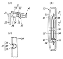
発明の実施の形態を図面を参照して説明する。図1は本発明に係る綴具の一実施形態の操作レバーを持ち上げた状態の概略斜視図、図2(a)は図1の平面図、図2(b)は(a)のA−A矢視図、図3は図1の右側面図、図4(a)は図2のB−B線に沿う要部拡大断面図、図4(b)は押圧板の底面図、図4(c)は図4(b)のC−C拡大矢視図、図5はレバーの脱落防止機構を示し、(a)は脱出不能状態の一部破断側面図、(b)は脱出可能状態の一部破断側面図、図6はリンクばねの取付状態を示す要部分解斜視図、図7は綴具をファイルに固定する状態を示す概略斜視図である。
【0011】
図1〜7において、綴具1は、水平状の基部11とこの基部から長手方向に沿って2列の支持壁部12、13が立設された基体10と、この基体10の2列の支持壁部12、13に一対のクランクを有する平行リンク機構20を介して平行移動可能に支持され基体10の基部11に当接可能の押圧板30と、基体の2列の支持壁部12、13に揺動可能に支持される操作レバー40と、平行リンク機構20の間に位置し操作レバー40に連動して押圧板30を平行移動させると共に、操作レバー40の押し下げ位置において押圧板30を基体10の基部11に押圧するリンクばね50とを備える。
【0012】
基体10はABS樹脂等のプラスチックより一体成形され、支持壁部12は水平状の基部11の長手方向に沿って中央部に垂直方向に立設され、また、支持壁部13は長手方向に沿って基部11の左端から垂直方向に立設されている。支持壁部13は基部11の外形に沿って緩やかな曲面で構成されている。支持壁部12、13には操作レバー40およびリンクばね50を係合する係合突起14が突設されている。中央部の支持壁部12の右方は紙葉類を綴じるための綴じ部15となっており、長手方向に沿って2本の綴じ溝16、16が凹設されている。
【0013】
2列の支持壁部12、13には平行リンク機構20を構成する2つのクランク21、21を支持する受け孔が所定間隔をおいて形成され、この受け孔に2つのクランク21、21が揺動可能に支持されている。クランク21、21は腕部22の一側から一方向に突設され基体10の支持壁部12、13に枢支される枢支軸23と、腕部22の他側から他方向に突設され枢支軸23と段違い平行状態の保持軸24とを有し、枢支軸23が2列の支持壁部12、13の受け孔に挿入され支持されるものである。クランク21、21の保持軸24には押圧板30を保持するための小径の保持溝25が形成されている。なお、支持壁部12、13は平行状態の2列の平面状の壁で形成してもよい。
【0014】
ここで、クランク21、21の脱落防止機構について、図5を参照して説明する。クランク21、21は前記したとおり基体10の支持壁部12、13により揺動可能に支持されるものであり、基体10の上面にはクランクが係合可能の係止溝17、17が凹設してある。クランク21、21は枢支軸23と保持軸24とを連結する中心線に対し、中心線と一方の長辺26は距離d1が小さく、中心線と他方の長辺27は距離d2が大きく設定されている。すなわち、中心線に対し非対称な形状となっている。クランク21、21の枢支軸23側の端部は、枢支軸23を中心とする円弧部28と、この円弧部に連続し一方の長辺26に連続する傾斜部29とを形成してある。傾斜部29は長辺26に対し約120度に傾斜している。
【0015】
そして、円弧部28および他方の長辺27が基体10の係止溝17、17内に挿入可能に設定され、挿入時にはクランク21、21は枢支軸23の軸方向に移動が不能であり、通常の揺動範囲において脱落することはないように構成されている。従って、図5(b)のように、クランク21を傾斜部29が基体10と平行状態になるとき、あるいは2点鎖線にて示すようにクランク21が基体10と平行状態のときにはクランク21は係止溝17から脱出しているため、軸方向の移動が可能となりクランク21を基体10から取り外すことができる。
【0016】
押圧板30はプラスチックより形成され、図4に示すようにクランク21、21の保持軸24、24が係合する受け部31、31がクランクの受け孔と同じ間隔で形成されている。受け部31、31にはクランクの保持軸24の保持溝25に係合し軸方向の移動を阻止すると共に脱落を防止する係止突部32と、この係止突部を支点として保持軸24に対して押圧板30が傾斜することができるように支持する突部33とが形成されている。押圧板30の上面には前記した係止突部32および突部33を射出成形で形成するときの金型の抜き孔が形成されている。押圧板30の裏面には長手方向に2本の突起34、35が平行に突設されており、基体10の綴じ部15に凹設した綴じ溝16、16と対応している。受け部31、31の中間にはリンクばね50が係合する案内穴36が穿設されている。
【0017】
操作レバー40は基体10の2列の支持壁部12、13に揺動可能に支持されており、本例では平行リンク機構20を構成する一方のクランク21の外周に支持されている。操作レバー40はプラスチックより形成され、断面が略T字形をしており、垂直壁部には操作レバー40が揺動したときにリンクばね50との干渉を避ける切り欠き41、クランクの枢支軸23を避ける切り欠き42およびリンクばね50の一端が係合して移動可能の案内溝43が形成されている。案内溝43は外周側より直線部44、傾斜部45およびロック部46が形成されている。操作レバー40の支点側と反対の端部には、指で押圧する押圧部47が設けてある。操作レバー40は断面が略T字形をしているため、強度が大きくなっている。
【0018】
リンクばね50はステンレス鋼、ばね鋼等のばね材より形成され、ばね材が巻回されたばね部51と、このばね部の一端から延出形成され操作レバー40の案内溝43に連結される連動端部52と、ばね部51の他端から延出形成され押圧板30の中央部に穿設された案内穴36に係合する押圧端部53とを有しており、図2(b)に示されるように押圧端部53は先端部が下方に向けて、言い換えると基体10の方向に屈曲されている。このため押圧板30は操作レバー40により平行移動され、基体10の基部11に当接するときに傾斜状態で先ず先端部が当接するように構成されている。押圧板30の案内穴36の形状は、リンクばね50の外径より大径の円弧で形成された長円穴であり、リンクばね50の押圧端部53が案内穴36内で長手方向に移動可能なように構成されている。
【0019】
リンクばね50のばね部51は、図2aおよび図6に示されるように、側方より基体10の支持壁部13の受け孔を介してロック軸55が挿入され、このロック軸55がばね部と他方の支持壁部12の受け孔を順に通過することにより支持されるものである。こうしてばね部が基体10の2列の支持壁部12、13により支持されることで、リンクばねは基体10に支持される。ロック軸55は2つのロック爪56、56を有し、基体10の下面に形成されたロック凹部(図示せず)に係合することにより基体10に固定される。ロック軸55もプラスチックより形成されている。このように、綴具1はリンクばね50を除くすべての部品がプラスチックにより形成されている。
【0020】
綴具1は前記のように構成され、例えばファイルの台紙に固定されるものである。すなわち、基体10の下面には第2図示のように基体10の中心寄りの支持壁部12に対応して2つの取付穴18、18が穿設されており、第2、7図示のようにファイルの台紙60を綴具1の下面に対接させ、例えばプラスドライバに対応する十字穴を有する2本の取付ねじ19、19を取付穴18、18に挿入してねじ込むことにより、台紙60に綴具1を固定することができる。このように台紙60に綴具1の中心寄りの支持壁部12が固定されるため、わずかなスペースの取付け箇所で、強固に固定することができる。支持壁部の肉厚が小さい場合には図示のように半円柱状の肉厚部を形成し、この肉厚部に対応して取付穴18、18を穿設してもよい。なお、綴具1は台紙60に限らず、ボード等に固定してバインダのように使用することも可能である。また、取付ねじ19に代えて、圧入ピンやスナップフィットピンのような着脱可能な取付具により台紙に綴具を固定するように構成してもよい。
【0021】
本発明に係る綴具1は前記した構成であり、以下に図8を参照して動作について説明する。図8は前記した綴具に紙葉類を綴じる動作説明図である。書類等の紙葉類65を綴じるときは、綴具1を図1のように操作レバー40を持ち上げた状態とし、基体10の綴じ部15上に紙葉類を載置する。操作レバー40を手前側に揺動させると、リンクばね50の連動端部52は案内溝43内を上方に向けて移動しロック部46を通過し、リンクばね50はばね部51を中心に回動して平行リンク機構20のクランク21、21と共に押圧板30を平行移動させる。そして、図8(a)のように押圧板30は紙葉類65の上面に当接し、押圧板30は先端部が下方に傾斜しているため先ず先端部が紙葉類65に当接する。この状態は紙葉類65がまだ綴じ込まれた状態ではなく、自由に移動することが可能である。
【0022】
操作レバー40をリンクばね50に抗して押し込むと押圧板30は紙葉類65を押圧し、押圧板30の先端部および先端側の突起35が紙葉類65を軽く保持する。操作レバー40をさらに押し込むと、リンクばねの中心のばね部51は捻られて押圧板30は紙葉類65を強く押圧し、押圧板30はクランク21、21の受け部31、31部分で水平状態となり2本の突起34、35が基体10の綴じ溝16、16部分を押圧して紙葉類65を固く保持して綴じ込む。そして、操作レバー40はリンクばね50の連動端部52の部分が図8(b)に示されるように基体10の係合突起14に係合してロックされる。
【0023】
紙葉類65を外すときは、図8(b)の状態から操作レバー40の押圧部47を右方に移動させると、リンクばねの連動端部52が係合突起14から外れ、リンクばね50のばね力により操作レバー40は上方に持ち上げられる。これにより押圧板30は基体10への押圧が解除され、紙葉類65はフリーの状態となり自由に外すことができる。操作レバー40をさらに上方に揺動させることによりリンクばね50の連動端部52は案内溝43のロック部46に係合し、操作レバー40は垂直状態に保持される。このように本発明に係る綴具1によれば、紙葉類65を極めて容易に綴じ込むことができ、取り外しも容易に行える。また、紙葉類65を仮止め状態で移動することができるため、所定の位置に綴じ込むことが容易に行える。平行リンク機構20は、クランク21の枢支軸23が2列の支持壁部12、13により支持されているため支持が強固であり、操作レバー40も支持壁部12、13により支持されているため支持が強固であり、紙葉類65を長期にわたって安定して綴じ込むことができる。
【0024】
本発明に係る綴具1を組み立てるときは、基体10の支持壁部12、13の間の所定位置に操作レバー40を挿入し、クランク21を図5(b)のような状態で支持壁部12、13の受け孔に挿入して操作レバー40を揺動可能に支持する。そして、他方のクランク21も同様に支持壁部12、13の受け孔に挿入する。つぎに、リンクばね50の連動端部52を案内溝43に係合させてクランク21、21の間の所定位置にばね部51を位置させ、支持壁部13の側方よりロック軸55を挿入してばね部51を支持する。このあと、リンクばね50の押圧端部53を押圧板30の案内穴36に挿入し、押圧板30の受け部31、31にクランク21、21の保持軸24、24を対応させて押し込む。これにより、受け部の係止突部32がクランク21の保持溝25に嵌合し、突部33が保持軸24を保持して両者はスナップフィットにより結合される。
【0025】
綴具1を例えば廃棄するときは、ロック軸55を挿入方向と反対方向に移動させるとロック爪56、56は基体10のロック凹部から容易に外れ、ロック軸55を容易に外すことができる。リンクばね50はばね部51が自由となり基体10から外すことができ、押圧板30の案内穴36から押圧端部53を外し、操作レバー40の案内溝43から連動端部52を外す。そして、クランク21、21に対し、押圧板30を上方に強く持ち上げるとクランク21の保持軸24から押圧板30の受け部31は容易に外すことができる。
【0026】
このようにして、綴具1は容易に分解することができ、金属部品であるリンクばね50とプラスチック部品である基体10、クランク21、21、押圧板30および操作レバー40とに分解することができる。また、綴具1をファイルの台紙60から外す場合は、取付ねじ19、19をプラスドライバにより外すことにより、容易に綴具1と台紙60とを分離することができる。
【0027】
【発明の効果】
以上説明したように、本発明によれば、基体の2列の支持壁部に平行リンク機構を介して押圧板を平行移動可能に支持し、基体の2列の支持壁部に操作レバーを揺動可能に支持するため強度的に優れ、紙葉類を長期にわたって安定して綴じ込むことができる。リンクばねは押圧端部の先端が下方に向けて屈曲されているため、紙葉類を綴じ込むときに移動しやすく所定の位置に綴じ込むことができる。また、基体は2列の支持壁部が形成され、クランクは2列の支持壁部に支持されて強度が大きいため、プラスチックで形成することが可能となり、製造および組立が容易に行える。さらに、本発明に係る綴具および綴具を備えるファイルは分解が容易であり、例えば廃棄時にプラスチック部品と金属部品とを容易に分別することができ廃棄が容易となるという効果を奏する。
【図面の簡単な説明】
【図1】本発明に係る綴具の一実施形態の操作レバーを持ち上げた状態の概略斜視図である。
【図2】(a)は図1の平面図、(b)は(a)のA−A矢視図である。
【図3】図1の右側面図である。
【図4】(a)は図2のB−B線に沿う要部拡大断面図、(b)は押圧板の底面図、(c)は(b)のC−C拡大矢視図
【図5】レバーの脱落防止機構を示し、(a)は脱出不能状態の一部破断側面図、(b)は脱出可能状態の一部破断側面図である。
【図6】リンクばねの取付状態を示す要部分解斜視図である。
【図7】本発明に係る綴具をファイルに固定する状態を示す概略斜視図である。
【図8】本発明に係る綴具に紙葉類を綴じる動作説明図であり、(a)は押圧板が紙葉類に当接した状態を示し、(b)は紙葉類を押さえ込んで閉じた状態を示す。
【符号の説明】
1 綴具
10 基体
11 基部
12、13 支持壁部
14 係合突起
15 綴じ部
16 綴じ溝
17 係止溝
18 取付穴
19 取付ねじ
20 平行リンク機構
21 クランク
22 腕部
23 枢支軸
24 保持軸
25 保持溝
26、27 長辺
28 円弧部
29 傾斜部
30 押圧板
31 受け部
32 係止突部
33 突部
34、35 突起
36 案内穴
40 操作レバー
41、42 切り欠き
43 案内溝
44 直線部
45 傾斜部
46 ロック部
47 押圧部
50 リンクばね
51 ばね部
52 連動端部
53 押圧端部
55 ロック軸
56 ロック爪
60 台紙
65 紙葉類[0001]
BACKGROUND OF THE INVENTION
The present invention relates to a binding tool that presses and binds paper sheets, and in particular, a binding tool and a binding tool that presses and binds paper sheets between a base plate and a pressing plate that can be moved in parallel by operation of a swingable operation lever. It relates to a file with tools.
[0002]
[Prior art]
2. Description of the Related Art Conventionally, a binding tool that is fixed to a file or the like and presses and binds paper sheets is made of a metal base having a rising wall portion and a horizontal base, an operation lever that is swingably supported by the base, and the base. It is configured to be supported by a parallel link mechanism so as to be movable in parallel, and a pressing plate that presses and binds paper sheets together with the horizontal base of the substrate in conjunction with the operation lever. In this type of binding tool, it is necessary to press the pressing plate against the base body with a strong spring force in order to press the paper sheets, and the base body and the parallel link mechanism are conventionally made of metal.
[0003]
[Problems to be solved by the invention]
However, the above-described binding tool has a problem that metal bases, plastic operation levers, and the like are mixed, and the metal parallel link mechanism portion requires caulking work, which makes manufacture complicated. Further, when discarding the binding tool, it is necessary to separate the metal portion and the plastic portion, but it is not easy to separate the metal caulking portion, and there is a risk of injury during the separation operation.
[0004]
The present invention has been made to solve the above-mentioned problems, and there is no problem in strength even when a plastic base or a parallel link mechanism is used, and the manufacture, assembly, and disassembly of the file including the binding tool and the binding tool. To provide a file including a binding tool and a binding tool that can be easily removed, the binding tool can be easily removed from the cover of the file at the time of disposal, and the plastic part and the metal part of the binding tool can be easily separated. With the goal.
[0005]
[Means for Solving the Problems]
In order to achieve the above-mentioned object, a binding device according to the present invention includes a horizontal base, a base on which two rows of support walls are erected from the base along the longitudinal direction, and two rows of support for the base. The wall is supported by a parallel link mechanism having a pair of cranks so as to be able to move in parallel, a pressing plate capable of contacting the base of the base, and supported by two rows of support walls of the base in a swingable manner. A link spring that is positioned between the operation lever and the parallel link mechanism, moves the pressing plate in parallel with the operating lever, and presses the pressing plate against the base of the base body at the depressed position of the operating lever; A spring portion provided on the link spring and formed by winding a spring material, and a lock shaft that can be inserted into and removed from the spring portion from a side of the support wall portion .
[0006]
The link spring includes a spring portion held by the base, an interlocking end portion that extends from one end of the spring portion and is connected to the operation lever, and a pressing end that extends from the other end of the spring portion and engages the pressing plate. It is advantageous that the pressing end portion is bent toward the base portion of the base body.
[0007]
The pair of cranks of the parallel link mechanism includes a pivot shaft projecting in one direction from one side of the arm portion and pivotally supported by the support wall portion of the base, and projecting in the other direction from the other side of the arm portion. It has a supporting shaft and a holding shaft that is in a parallel state, and is prevented from falling off in the normal swing range of the crank. The base, the operating lever, the pressing plate, and the crank of the parallel link mechanism are preferably made of plastic. It is preferable that an attachment hole for inserting an attachment for fixing the binding tool to the file mount is formed in the support wall near the center of the base.
[0008]
In addition, the file including the binding device according to the present invention is characterized in that the binding device configured as described above is fixed to the mount with a detachable attachment such as an attachment screw.
[0009]
According to the binding device and the file including the binding device configured as described above, the base body is excellent in strength by the two rows of support wall portions, and the operation lever and the parallel link mechanism are supported by the two rows of support wall portions. Support is stable. For this reason, the paper sheets can be stapled stably over a long period of time, and even if all the parts except the link spring are made of plastic, the paper sheets can be similarly stapled stably over a long period of time. Moreover, disassembly is easy, for example, plastic parts and metal parts can be easily separated at the time of disposal.
[0010]
DETAILED DESCRIPTION OF THE INVENTION
Embodiments of the invention will be described with reference to the drawings. FIG. 1 is a schematic perspective view showing a state in which an operation lever of an embodiment of a binding device according to the present invention is lifted, FIG. 2A is a plan view of FIG. 1, and FIG. 2B is AA of FIG. FIG. 3 is a right side view of FIG. 1, FIG. 4A is an enlarged cross-sectional view of a main part along the line BB in FIG. 2, FIG. 4B is a bottom view of the pressing plate, and FIG. 4C is an enlarged view taken along the line CC in FIG. 4B, FIG. 5 shows a mechanism for preventing the lever from dropping out, FIG. 5A is a partially broken side view showing a state in which the lever cannot be pulled out, and FIG. FIG. 6 is a partially broken side view, FIG. 6 is an exploded perspective view of the main part showing the attachment state of the link spring, and FIG. 7 is a schematic perspective view showing a state in which the binding tool is fixed to the file.
[0011]
1 to 7, the
[0012]
The
[0013]
The two rows of
[0014]
Here, the de-drop preventing mechanism of the
[0015]
The
[0016]
The
[0017]
The
[0018]
The
[0019]
As shown in FIGS. 2a and 6, the
[0020]
The
[0021]
The
[0022]
When the operating
[0023]
When removing the
[0024]
When assembling the
[0025]
For example, when the
[0026]
In this way, the
[0027]
【The invention's effect】
As described above, according to the present invention, the pressing plate is supported on the two support wall portions of the base body via the parallel link mechanism so as to be movable in parallel, and the operation lever is rocked on the two support wall portions of the base body. Since it is supported so as to be movable, it is excellent in strength and can bind paper sheets stably over a long period of time. The link spring is bent at the tip end of the pressing end downward, so that it can be easily moved when binding paper sheets and can be bound at a predetermined position. Further, since the base body is formed with two rows of support wall portions and the crank is supported by the two rows of support wall portions and has high strength, it can be formed of plastic and can be easily manufactured and assembled. Further, the binding device and the file including the binding device according to the present invention can be easily disassembled. For example, the plastic part and the metal part can be easily separated at the time of disposal, and the disposal is facilitated.
[Brief description of the drawings]
FIG. 1 is a schematic perspective view of a state in which an operation lever of an embodiment of a binding device according to the present invention is lifted.
2A is a plan view of FIG. 1, and FIG. 2B is a view taken along the line AA of FIG.
FIG. 3 is a right side view of FIG. 1;
4A is an enlarged cross-sectional view of a main part taken along the line BB in FIG. 2, FIG. 4B is a bottom view of the pressing plate, and FIG. 4C is an enlarged view taken along the line CC in FIG. 5 shows a mechanism for preventing the lever from dropping out, in which (a) is a partially broken side view in a state where it cannot be pulled out, and (b) is a partially broken side view in a state where it is possible to escape.
FIG. 6 is an exploded perspective view of a main part showing a mounting state of a link spring.
FIG. 7 is a schematic perspective view showing a state in which the binding device according to the present invention is fixed to a file.
FIGS. 8A and 8B are operation explanatory views for binding paper sheets to the binding device according to the present invention, in which FIG. 8A shows a state where the pressing plate is in contact with the paper sheets, and FIG. Indicates the closed state.
[Explanation of symbols]
DESCRIPTION OF
Claims (6)
Priority Applications (1)
| Application Number | Priority Date | Filing Date | Title |
|---|---|---|---|
| JP00474399A JP4128289B2 (en) | 1999-01-11 | 1999-01-11 | Binding device and file with binding device |
Applications Claiming Priority (1)
| Application Number | Priority Date | Filing Date | Title |
|---|---|---|---|
| JP00474399A JP4128289B2 (en) | 1999-01-11 | 1999-01-11 | Binding device and file with binding device |
Publications (3)
| Publication Number | Publication Date |
|---|---|
| JP2000203186A JP2000203186A (en) | 2000-07-25 |
| JP2000203186A5 JP2000203186A5 (en) | 2006-02-23 |
| JP4128289B2 true JP4128289B2 (en) | 2008-07-30 |
Family
ID=11592407
Family Applications (1)
| Application Number | Title | Priority Date | Filing Date |
|---|---|---|---|
| JP00474399A Expired - Lifetime JP4128289B2 (en) | 1999-01-11 | 1999-01-11 | Binding device and file with binding device |
Country Status (1)
| Country | Link |
|---|---|
| JP (1) | JP4128289B2 (en) |
Cited By (1)
| Publication number | Priority date | Publication date | Assignee | Title |
|---|---|---|---|---|
| CN111761959A (en) * | 2020-06-04 | 2020-10-13 | 姜友全 | Single-foot fixed stapler |
Families Citing this family (2)
| Publication number | Priority date | Publication date | Assignee | Title |
|---|---|---|---|---|
| CN100349755C (en) * | 2002-01-10 | 2007-11-21 | 利高文具制造厂有限公司 | Wrench-type clip for folder |
| JP4248291B2 (en) * | 2003-04-08 | 2009-04-02 | コクヨ株式会社 | Binding tool and file |
-
1999
- 1999-01-11 JP JP00474399A patent/JP4128289B2/en not_active Expired - Lifetime
Cited By (2)
| Publication number | Priority date | Publication date | Assignee | Title |
|---|---|---|---|---|
| CN111761959A (en) * | 2020-06-04 | 2020-10-13 | 姜友全 | Single-foot fixed stapler |
| CN111761959B (en) * | 2020-06-04 | 2021-08-13 | 义乌市旻具五金工具有限公司 | Single-foot fixed stapler |
Also Published As
| Publication number | Publication date |
|---|---|
| JP2000203186A (en) | 2000-07-25 |
Similar Documents
| Publication | Publication Date | Title |
|---|---|---|
| EP1366862A1 (en) | Stapler | |
| JP4128289B2 (en) | Binding device and file with binding device | |
| US20090067914A1 (en) | Binding device | |
| EP1384598A1 (en) | Fastener | |
| JPH05309986A (en) | Binder for loose-leaf | |
| JP4248291B2 (en) | Binding tool and file | |
| JP4023884B2 (en) | Contact opening / closing mechanism of switch device | |
| EP0941870A2 (en) | Transverse button compression bar | |
| JP4218466B2 (en) | Binding tool and file | |
| JP2580469B2 (en) | Binding | |
| JP3053955U (en) | Stapler binding operation preventing stopper structure and stapler with movable remover provided with the stopper structure | |
| JPH0322789Y2 (en) | ||
| JP2000203186A5 (en) | ||
| JP3013200U (en) | stapler | |
| JPS6035146Y2 (en) | push button switch | |
| JP2538216Y2 (en) | File binding device | |
| JPH08174445A (en) | Stapler | |
| KR200254389Y1 (en) | a stapler | |
| JPS5815193Y2 (en) | presser foot | |
| JPH01244897A (en) | Clamping device for loose-leaf holder | |
| JP2000247084A (en) | Filing device | |
| JP3004117U (en) | Stamp box | |
| JPS589375Y2 (en) | Core slide setting mechanism in push button tuner | |
| JPH10254432A (en) | Hammer in keyboard device | |
| JPH0217387Y2 (en) |
Legal Events
| Date | Code | Title | Description |
|---|---|---|---|
| A521 | Written amendment |
Free format text: JAPANESE INTERMEDIATE CODE: A523 Effective date: 20051228 |
|
| A621 | Written request for application examination |
Free format text: JAPANESE INTERMEDIATE CODE: A621 Effective date: 20051228 |
|
| A977 | Report on retrieval |
Free format text: JAPANESE INTERMEDIATE CODE: A971007 Effective date: 20080110 |
|
| A131 | Notification of reasons for refusal |
Free format text: JAPANESE INTERMEDIATE CODE: A131 Effective date: 20080206 |
|
| A521 | Written amendment |
Free format text: JAPANESE INTERMEDIATE CODE: A523 Effective date: 20080403 |
|
| TRDD | Decision of grant or rejection written | ||
| A01 | Written decision to grant a patent or to grant a registration (utility model) |
Free format text: JAPANESE INTERMEDIATE CODE: A01 Effective date: 20080423 |
|
| A01 | Written decision to grant a patent or to grant a registration (utility model) |
Free format text: JAPANESE INTERMEDIATE CODE: A01 |
|
| A61 | First payment of annual fees (during grant procedure) |
Free format text: JAPANESE INTERMEDIATE CODE: A61 Effective date: 20080514 |
|
| FPAY | Renewal fee payment (event date is renewal date of database) |
Free format text: PAYMENT UNTIL: 20110523 Year of fee payment: 3 |
|
| R150 | Certificate of patent or registration of utility model |
Free format text: JAPANESE INTERMEDIATE CODE: R150 |
|
| FPAY | Renewal fee payment (event date is renewal date of database) |
Free format text: PAYMENT UNTIL: 20110523 Year of fee payment: 3 |
|
| FPAY | Renewal fee payment (event date is renewal date of database) |
Free format text: PAYMENT UNTIL: 20110523 Year of fee payment: 3 |
|
| FPAY | Renewal fee payment (event date is renewal date of database) |
Free format text: PAYMENT UNTIL: 20120523 Year of fee payment: 4 |
|
| FPAY | Renewal fee payment (event date is renewal date of database) |
Free format text: PAYMENT UNTIL: 20120523 Year of fee payment: 4 |
|
| FPAY | Renewal fee payment (event date is renewal date of database) |
Free format text: PAYMENT UNTIL: 20130523 Year of fee payment: 5 |
|
| FPAY | Renewal fee payment (event date is renewal date of database) |
Free format text: PAYMENT UNTIL: 20130523 Year of fee payment: 5 |
|
| FPAY | Renewal fee payment (event date is renewal date of database) |
Free format text: PAYMENT UNTIL: 20130523 Year of fee payment: 5 |
|
| FPAY | Renewal fee payment (event date is renewal date of database) |
Free format text: PAYMENT UNTIL: 20140523 Year of fee payment: 6 |
|
| R250 | Receipt of annual fees |
Free format text: JAPANESE INTERMEDIATE CODE: R250 |
|
| R250 | Receipt of annual fees |
Free format text: JAPANESE INTERMEDIATE CODE: R250 |
|
| R250 | Receipt of annual fees |
Free format text: JAPANESE INTERMEDIATE CODE: R250 |
|
| R250 | Receipt of annual fees |
Free format text: JAPANESE INTERMEDIATE CODE: R250 |
|
| R250 | Receipt of annual fees |
Free format text: JAPANESE INTERMEDIATE CODE: R250 |
|
| EXPY | Cancellation because of completion of term |