JP4127820B2 - Method and apparatus for packaging articles - Google Patents
Method and apparatus for packaging articles Download PDFInfo
- Publication number
- JP4127820B2 JP4127820B2 JP2003534265A JP2003534265A JP4127820B2 JP 4127820 B2 JP4127820 B2 JP 4127820B2 JP 2003534265 A JP2003534265 A JP 2003534265A JP 2003534265 A JP2003534265 A JP 2003534265A JP 4127820 B2 JP4127820 B2 JP 4127820B2
- Authority
- JP
- Japan
- Prior art keywords
- bag
- web
- stud
- distance
- longitudinal groove
- Prior art date
- Legal status (The legal status is an assumption and is not a legal conclusion. Google has not performed a legal analysis and makes no representation as to the accuracy of the status listed.)
- Expired - Fee Related
Links
Images


Classifications
-
- B—PERFORMING OPERATIONS; TRANSPORTING
- B65—CONVEYING; PACKING; STORING; HANDLING THIN OR FILAMENTARY MATERIAL
- B65B—MACHINES, APPARATUS OR DEVICES FOR, OR METHODS OF, PACKAGING ARTICLES OR MATERIALS; UNPACKING
- B65B43/00—Forming, feeding, opening or setting-up containers or receptacles in association with packaging
- B65B43/12—Feeding flexible bags or carton blanks in flat or collapsed state; Feeding flat bags connected to form a series or chain
-
- B—PERFORMING OPERATIONS; TRANSPORTING
- B65—CONVEYING; PACKING; STORING; HANDLING THIN OR FILAMENTARY MATERIAL
- B65B—MACHINES, APPARATUS OR DEVICES FOR, OR METHODS OF, PACKAGING ARTICLES OR MATERIALS; UNPACKING
- B65B43/00—Forming, feeding, opening or setting-up containers or receptacles in association with packaging
- B65B43/42—Feeding or positioning bags, boxes, or cartons in the distended, opened, or set-up state; Feeding preformed rigid containers, e.g. tins, capsules, glass tubes, glasses, to the packaging position; Locating containers or receptacles at the filling position; Supporting containers or receptacles during the filling operation
- B65B43/46—Feeding or positioning bags, boxes, or cartons in the distended, opened, or set-up state; Feeding preformed rigid containers, e.g. tins, capsules, glass tubes, glasses, to the packaging position; Locating containers or receptacles at the filling position; Supporting containers or receptacles during the filling operation using grippers
- B65B43/465—Feeding or positioning bags, boxes, or cartons in the distended, opened, or set-up state; Feeding preformed rigid containers, e.g. tins, capsules, glass tubes, glasses, to the packaging position; Locating containers or receptacles at the filling position; Supporting containers or receptacles during the filling operation using grippers for bags
-
- B—PERFORMING OPERATIONS; TRANSPORTING
- B65—CONVEYING; PACKING; STORING; HANDLING THIN OR FILAMENTARY MATERIAL
- B65B—MACHINES, APPARATUS OR DEVICES FOR, OR METHODS OF, PACKAGING ARTICLES OR MATERIALS; UNPACKING
- B65B43/00—Forming, feeding, opening or setting-up containers or receptacles in association with packaging
- B65B43/26—Opening or distending bags; Opening, erecting, or setting-up boxes, cartons, or carton blanks
- B65B43/267—Opening of bags interconnected in a web
-
- B—PERFORMING OPERATIONS; TRANSPORTING
- B65—CONVEYING; PACKING; STORING; HANDLING THIN OR FILAMENTARY MATERIAL
- B65B—MACHINES, APPARATUS OR DEVICES FOR, OR METHODS OF, PACKAGING ARTICLES OR MATERIALS; UNPACKING
- B65B9/00—Enclosing successive articles, or quantities of material, e.g. liquids or semiliquids, in flat, folded, or tubular webs of flexible sheet material; Subdividing filled flexible tubes to form packages
- B65B9/06—Enclosing successive articles, or quantities of material, in a longitudinally-folded web, or in a web folded into a tube about the articles or quantities of material placed upon it
- B65B9/08—Enclosing successive articles, or quantities of material, in a longitudinally-folded web, or in a web folded into a tube about the articles or quantities of material placed upon it in a web folded and sealed transversely to form pockets which are subsequently filled and then closed by sealing
- B65B9/087—Enclosing successive articles, or quantities of material, in a longitudinally-folded web, or in a web folded into a tube about the articles or quantities of material placed upon it in a web folded and sealed transversely to form pockets which are subsequently filled and then closed by sealing the web advancing continuously
Abstract
Description
吊るした薄膜袋の中に物品またはばら物を包装するための方法。 A method for wrapping articles or loose articles in a suspended thin film bag.
本発明は、薄膜袋の中に物品を包装するための方法と装置に関する。薄膜袋は連続ウェブの状態で個別に物品を充てんする充てんステーションを通して運ばれ、次いで袋が閉じられて、個別包装物とするために連続ウェブから分離される、 The present invention relates to a method and apparatus for packaging articles in thin film bags. The thin film bags are conveyed through a filling station that individually fills the articles in a continuous web, and then the bags are closed and separated from the continuous web for individual packaging.
この技術の基本的一例が特許文献EP−696997に記載されている。これは、袋物ウェブの上縁両区域に曲がったリム部分を備え、そのリム部分に搬送バーへ入れるための溝を形成している。バーは搬送方向において袋物に開口部を形成させるために相互に開き、例えば上にある漏斗を通して充てんされ、その後、充てんされた袋物を再び一時的に閉じるために搬送バーは相互に狭められる。次にこれらを、後述の溝部分を溶接することによって完全に閉じることができ、その後、これらを切断して互いに物品に分離する。別法として、溝部分の代わりに、袋物を完全に対応して搬送するためにスロット付きの搬送管の中に受け入れることのできる縁肉厚部を設けることもできる。 A basic example of this technique is described in Patent Document EP-696997. This includes a rim portion bent at both upper edge areas of the bag web, and a groove is formed in the rim portion to enter the transport bar. The bars open to each other to form an opening in the bag in the transport direction and are filled, for example, through an overlying funnel, and then the transport bars are narrowed together to temporarily close the filled bag again. They can then be completely closed by welding the groove portions described below, after which they are cut and separated into articles. Alternatively, instead of the groove portion, it is also possible to provide a rim thickness that can be received in a slotted conveying tube for the full corresponding conveyance of the bag.
それ以来、例えば特許文献EP0555321Bに記載のように、袋物ウェブの面している上縁部を掴んで支えるための別形式の提案がされている。この場合、折りたたまれた袋物ウェブの上縁部領域の設計に対する特別の要求なしに、上記の目的のために専用の掴みチェーンが使用される。これは、最終製品として、局部的に厚い部分のない簡単な巻き取られた平坦な薄膜ウェブを使用することができる点で実質的な意味があるが、その代わりに、チェーンとの安全な係合のために袋物の対向する縁部を案内することに関して、およびこれらのチェーンの望ましくは安価な実施形態に関して、大きな問題が存在する。 Since then, another type of proposal for gripping and supporting the upper edge of the bag web has been proposed, as described, for example, in patent document EP0555321B. In this case, a dedicated grip chain is used for this purpose without any special requirements for the design of the upper edge area of the folded bag web. This has substantial implications in that the end product can use a simple wound flat thin film web with no locally thick parts, but instead a safe engagement with the chain. There are significant problems with guiding the opposite edges of the bag for alignment, and with the desirably inexpensive embodiments of these chains.
さらにまた特許文献EP0396838およびEP0825116には、薄膜の平らなパイプ状ウェブを設けることができ、この平らなパイプ状ウェブは、その上縁部に沿って連続的に切り開くことができ、次いでこうして切り開いた上縁部を開いて掴み、上縁部は溝として特に設計されることも厚い部分を伴って設計されることもない。このことは、袋ウェブ製造に関する要件の明らかな簡略化を示すことになる。切り開かれた上縁部分は、縦方向凹部と対応する押圧コードとを伴って作られたそれぞれの移動ベルトの間で広げられて圧迫され、これによって適切に堅固なキャリア係合を確立することができる。 Furthermore, the patent documents EP 0 396 838 and EP 0 825 116 can be provided with a thin flat pipe-like web, which can be continuously cut along its upper edge, and thus cut open. The upper edge is opened and gripped, and the upper edge is not specifically designed as a groove or with a thicker part. This represents a clear simplification of the requirements for bag web manufacture. The cut-up upper edge portion is spread and compressed between each moving belt made with a longitudinal recess and a corresponding pressing cord, thereby establishing an adequately firm carrier engagement. it can.
しかしながら、この係合は、袋の上縁部とベルト運搬用の付属手段との間で起り得る軸方向滑りよりも堅固ではなく、これによって、運ばれた物品がコンベヤ・ベルトと完全に同期して運ばれたか否かという不確実性が生じることもある。その上に、コンベヤ・ベルトの間で圧迫されるウェブ側部の区域の高さ位置に関して偏差が生じることもあり、これは、充てんされた袋がこの正確な目的のために意図された位置、例えば袋上の印刷に関する位置で完全に閉じられたどうかについて重要となるであろう。 However, this engagement is less rigid than the axial slip that can occur between the top edge of the bag and the belt transport accessory, which ensures that the conveyed items are perfectly synchronized with the conveyor belt. Uncertainty of whether it was carried or not may occur. In addition, deviations may occur with respect to the height position of the area of the web side that is squeezed between the conveyor belts, which is the position at which the filled bag is intended for this precise purpose, For example, it may be important whether it is completely closed in a position for printing on the bag.
特許文献DKPA199800548には、簡単にした平らな袋ウェブを使用する構造が記載されており、すなわちウェブが単一キャリアの上に導入されると開口縁部は単に閉じられ、1つのステーションにおいて連続的に切り開かれ、このステーションにおいて直立したリム条片の部分が相対するチェーンの上に置かれるように広げられる。予めこれらの条片の部分は一列の孔を伴って作られており、これらの孔は、下方に折りたたむ間にキャリア・チェーンの上方に向いた保持スタッドの中に下向きに導かれ、これによって、開口縁部に特別の輪郭付けをすることなく安全なキャリアおよび推進係合が達成される。 The patent document DKPA 199800548 describes a structure using a simplified flat bag web, i.e. when the web is introduced on a single carrier, the opening edge is simply closed and continuously in one station. And at this station, the upright rim strip portions are spread so that they rest on the opposite chain. The strip portions are pre-made with a row of holes, which are guided downward into the holding studs facing upwards of the carrier chain during folding down, thereby Safe carrier and propulsion engagement is achieved without special contouring of the opening edge.
最後に説明した構造を使用している間に、この構造が上記の利点を備えていることは事実であり、これらは簡単な方法で得られることがわかった。本発明の目的は、薄膜袋の中に物品またはばら物を包装するための方法であって、従来の技術による構造に対してより簡略化され、かつその方法を実施する設備をより速い速度で通ることができる充てんステーションを通って、前記物品が連続ウェブの状態で運ばれる方法を提供することである。 While using the last described structure, it was true that this structure provided the above advantages and it was found that they were obtained in a simple manner. The object of the present invention is a method for packaging an article or bulk in a thin film bag, which is more simplified than a structure according to the prior art, and the equipment for carrying out the method at a higher speed. Providing a method in which the article is conveyed in a continuous web through a filling station that can be passed.
これは、滑らかなガイド・レールの上を搬送中に袋ウェブが左チェーンと右チェーンとの間に導入され、これらのチェーンは、袋ウェブの孔の間の距離と同じ距離で水平スタッドを支持しており、これらの水平スタッドは袋ウェブに形成された孔の中に各側から導入され、水平スタッドの端部を囲む長手方向の溝によってスタッドが袋ウェブを保持すること確実に行うことができる方法によって達成される。 This is because the bag web is introduced between the left and right chains during transport over smooth guide rails and these chains support horizontal studs at the same distance as the distance between the holes in the bag web These horizontal studs are introduced from each side into a hole formed in the bag web to ensure that the stud holds the bag web by means of a longitudinal groove surrounding the end of the horizontal stud. Is achieved by a method that can.
本方法を実施するための装置は、ガイド・レールがより広いマンドレル形状のレール部分に変化し、そのマンドレルの各側には第1長手方向の溝を備えおり、このレール部分が第1長手方向の溝と連続する第2長手方向の溝を有する楔形状の本体に変化し、この楔形状の本体は2つの平行な第3長手方向の溝に変化し、これによって、袋ウェブの孔の間の距離に対応する距離を有する水平スタッドを備えた2本のエンドレス・チェーンが、スタッドがどこでも長手方向の溝の内部にあるように、レールとガイド・ロールによって長手方向の溝に対して維持され、2本のチェーンが互いに向き合っているスタッドとともに並行に移動し、また第3長手方向の溝間の距離が袋の所望の開口部を得るために必要な距離に対応している。 An apparatus for carrying out the method changes the guide rail to a wider mandrel-shaped rail portion, with a first longitudinal groove on each side of the mandrel, the rail portion being in the first longitudinal direction. A wedge-shaped body having a second longitudinal groove that is continuous with the groove, and the wedge-shaped body is transformed into two parallel third longitudinal grooves, between the holes of the bag web. Two endless chains with horizontal studs with a distance corresponding to the distance of are maintained against the longitudinal grooves by rails and guide rolls so that the studs are inside the longitudinal grooves everywhere The two chains move in parallel with the studs facing each other, and the distance between the third longitudinal grooves corresponds to the distance necessary to obtain the desired opening of the bag.
図面を参照して、以下に本発明をさらに詳細に説明する。
図1は本方法を実施する装置における本質的構成部分を示す図である。
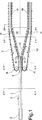
図2a〜dは袋ウェブ導入部の各断面を示す図である。
図3は取付け部とスタッドとを有するチェーンのリンクを示す図である。
The present invention will be described in more detail below with reference to the drawings.
FIG. 1 shows the essential components of an apparatus for carrying out the method.
2a to 2d are cross-sectional views of the bag web introduction part.
FIG. 3 is a view showing a link of a chain having a mounting portion and a stud.
合成材からなる袋ウェブ1が図示されていない貯蔵個所から滑らかなレール2(断面2a)の上を矢印の方向に運ばれる。レール2は袋の搬送方向に向いた丸い部分3を備えている。袋ウェブは、この目的のために設計されたプラスチック薄膜の上部分で吊され、図示されていない通例の切れ目および脆弱個所を備えている。さらにまた上部分は、一定の相互距離を有する孔である多くの打ち抜きを備えている。レールの形状が厚いマンドレル4(断面2b)に変わる。そのマンドレルの各側には溝5、6が設けられている。これらの溝はスタッド7に対応する幅と深さとを有し、スタッド7は、一定距離を有する取付け具8によって2本のエンドレス・チェーン9、10に配置されている。スタッドは、各側からのスタッドが袋ウェブの上部分の左側および右側における層11、12をそれぞれ貫通するように、袋ウェブ1と同期して移動する。プラスチック薄膜はマンドレル4とスタッドとによって広げられ、マンドレルの上側における垂直ナイフ13を通過し、その後、袋ウェブのここで分離させられた2つの部分11、12が、スタッドを備えたチェーンによって運ばれる。スタッド7の端部を囲むように設計された溝5、6によって、プラスチック薄膜はスタッドの端部を越えて滑り出ることはできない。
A bag web 1 made of synthetic material is conveyed in the direction of the arrow on a smooth rail 2 (cross section 2a) from a storage location not shown. The rail 2 is provided with a rounded portion 3 facing the bag transport direction. The bag web is hung on the upper part of a plastic film designed for this purpose and is provided with customary cuts and weak points not shown. Furthermore, the upper part is provided with a number of punches which are holes having a constant mutual distance. The shape of the rail changes to a thick mandrel 4 (section 2b).
マンドレルは楔状のブロック14(断面2c)に変わり、このブロック14は対応した長手方向の溝5’、6’を備え、袋ウェブ11、12がさらに運ばれる間、袋は次第に広げられる。最大にまで開けられると、ブロック14はなお長手方向の溝5”、6”を備えた縦方向レール15、16(断面2d)に変わる。これらのレールは袋を前方へ、充てん、密封、切り離しなどの通常のステーションの間の下側を搬送する。その間中ずっと、スタッド7を備えたチェーン9、10は、移送、および様々なローラRによるチェーンの案内を行い、レールは、プラスチック薄膜が滑って離れないようにするために、溝5、5’、5”、6、6’、6”の中にスタッドを留める働きをする。適当な個所に、駆動用大歯車Rが各チェーンのために置かれている。包装設備(図示せず)の端部において、スタッドは、チェーンがガイド・ロールの周りを走行することで離され、切り離された袋がこの位置で掴まれ、さらに運搬されるか、またはコンベヤ・ベルトの上に落とされる。図1は単なる概略図であり、したがって、分かりやすくするためいくつかの寸法は誇張されており、図2は少なくとも要素間の比率に関しては実際の構造に対応していることが注目される。
The mandrel changes to a wedge-shaped block 14 (cross-section 2c), which comprises a corresponding longitudinal groove 5 ', 6' so that the bag is gradually unfolded while the
チェーン(10)の1つが図3に示されており、ここでは、その他のリンクLはすべて、チェーンの平面図では突出したスタッドを備えた取付け具8を備えている。
One of the chains (10) is shown in FIG. 3, where all the other links L are equipped with a
従来の技術と比較して改良されたこの効果は、特に、本発明によればスタッド7はより短く、搬送中にプラスチック薄膜11、12をスタッド上に確実に留めておくために重力を必要としないという事実に帰するものである。
This effect, which is improved compared to the prior art, is in particular that according to the invention the
Claims (2)
袋ウェブ(1)がガイド・レール(2)の上を運ばれるとき、袋ウェブ(1)が水平スタッド(7)を支える左チェーンと右チェーン(9、10)との間に導入され、そのスタッドが各側から袋ウェブに形成された孔の中に導かれ、前記それぞれの長手方向の溝(5、5’、5”、6、6’、6”)が水平スタッド(7)の端部を囲んで、充てんステーションを通るコンベヤ・トラックに沿った袋ウェブ(1)のスタッドによる保持を確実にすることを特徴とする方法。Carried through the filling station in a continuous web state, the bag opening is kept open to accept the articles, the bags are then closed, and the articles or In the method of packaging loose material, the bag web (1) is first connected along its open edge by a connecting means controlled by guide means comprising smooth guide rails (2) and chains (9, 10). The chain is placed at the same distance as the distance between the holes at the opening edge of the bag web and passes through the filling station along the conveyor track along the facing opening edge of the bag. For holding and guiding forward, a stud (7) arranged to engage a hole in the opening edge is provided, and during passing, the guide means (4, 14, 15, 16) are filled with a filling station. To open the bag continuously in order to open the bag continuously, and then after filling the bag, the bag opening edge is connected to close the bag again, A method in which the guide rails (2) are spread over one another for continuous attachment to guide means (4, 14, 15, 16), the guide rails (2) being on each side a first longitudinal groove (5, 6). ), Which is designed with a wider mandrel-shaped rail part (4), which is continuous with a first longitudinal groove (5, 6) and a second longitudinal groove (5 ′, 6 ′). ) Having a wedge-shaped body (14), which is shaped to change into two parallel third longitudinal grooves (5 ″, 6 ″), thereby
Can a bag web (1) is carried over the guide rail (2), the bag web (1) is introduced between the left chain and right chain supporting the horizontal studs (7) (9, 10), The stud is led from each side into a hole formed in the bag web, said respective longitudinal grooves (5, 5 ', 5 ", 6, 6', 6") of the horizontal stud (7). A method characterized by ensuring the retention of the bag web (1) by a stud around the end and along the conveyor track through the filling station.
Applications Claiming Priority (2)
| Application Number | Priority Date | Filing Date | Title |
|---|---|---|---|
| DK200101481A DK200101481A (en) | 2001-10-08 | 2001-10-08 | Posedorn |
| PCT/DK2002/000671 WO2003031268A1 (en) | 2001-10-08 | 2002-10-07 | Method and apparatus for packing of items |
Publications (3)
| Publication Number | Publication Date |
|---|---|
| JP2005523204A JP2005523204A (en) | 2005-08-04 |
| JP2005523204A5 JP2005523204A5 (en) | 2005-11-17 |
| JP4127820B2 true JP4127820B2 (en) | 2008-07-30 |
Family
ID=8160755
Family Applications (1)
| Application Number | Title | Priority Date | Filing Date |
|---|---|---|---|
| JP2003534265A Expired - Fee Related JP4127820B2 (en) | 2001-10-08 | 2002-10-07 | Method and apparatus for packaging articles |
Country Status (22)
| Country | Link |
|---|---|
| US (1) | US6990787B2 (en) |
| EP (1) | EP1451069B1 (en) |
| JP (1) | JP4127820B2 (en) |
| KR (1) | KR100999337B1 (en) |
| CN (1) | CN1239353C (en) |
| AT (1) | ATE302144T1 (en) |
| AU (1) | AU2002349409B2 (en) |
| BR (1) | BR0213141B1 (en) |
| CA (1) | CA2466587C (en) |
| CZ (1) | CZ2004590A3 (en) |
| DE (1) | DE60205654T2 (en) |
| DK (2) | DK200101481A (en) |
| ES (1) | ES2247393T3 (en) |
| HK (1) | HK1071114A1 (en) |
| HU (1) | HUP0402312A3 (en) |
| MX (1) | MXPA04003203A (en) |
| NO (1) | NO331502B1 (en) |
| NZ (1) | NZ532468A (en) |
| PL (1) | PL205879B1 (en) |
| RU (1) | RU2293046C2 (en) |
| SI (1) | SI1451069T1 (en) |
| WO (1) | WO2003031268A1 (en) |
Families Citing this family (15)
| Publication number | Priority date | Publication date | Assignee | Title |
|---|---|---|---|---|
| DE102007027110A1 (en) * | 2007-06-13 | 2008-12-18 | Wacker Chemie Ag | Method and apparatus for packaging polycrystalline silicon breakage |
| AT10632U1 (en) * | 2008-04-07 | 2009-07-15 | Statec Anlagentechnik Gmbh | DEVICE FOR FILLING SAWS |
| CN101973414B (en) * | 2010-08-16 | 2012-05-23 | 上海嘉迪机械有限公司 | Conveying belt separating mechanism for full-automatic vacuum packaging machine |
| SE535972C2 (en) * | 2011-06-22 | 2013-03-12 | Pronova Ab | Apparatus and method of packing goods in an inflatable bag |
| CN102556385A (en) * | 2011-12-24 | 2012-07-11 | 湖州巨人机电有限公司 | Bag sleeving tool |
| CN102556423B (en) * | 2011-12-31 | 2013-10-02 | 宁波富邦电池有限公司 | Cell heat shrink film packaging machine |
| KR101511136B1 (en) | 2013-06-17 | 2015-04-20 | 주식회사 대성자동 포장기계 | Apparatus for sealing vinyl bag |
| DK177935B1 (en) * | 2013-10-07 | 2015-01-19 | Schur Technology As | Packaging web, filling apparatus and method for loading goods into bagpipes in a packaging web and making bags with two compartments of bagpipes |
| KR101591732B1 (en) | 2014-02-12 | 2016-02-05 | 주식회사 대성자동 포장기계 | Apparatus and method for forming plastic bag and packaging system including the same apparatus |
| NL2012820C (en) * | 2014-02-26 | 2015-08-27 | Fuji Seal International | Assembly and method for storing containers. |
| DK178533B1 (en) | 2014-06-30 | 2016-06-06 | Schur Tech As | Bag web and method of packing a product in foil bags using such a bag web |
| DK178173B1 (en) * | 2014-06-30 | 2015-07-20 | Schur Technology As | Method and apparatus for packing items, liquid or loose goods in foil bags and a bag web |
| DK178614B1 (en) | 2015-04-01 | 2016-08-22 | Schur Tech As | Bag run and method of making such bag run |
| NL2015348B1 (en) * | 2015-08-25 | 2017-03-16 | Fuji Seal Int Inc | System and method of discharging a tubular storage assembly |
| US20220234325A1 (en) * | 2019-05-09 | 2022-07-28 | Sealed Air Corporation (Us) | Guides for folded portions of inflatable webs |
Family Cites Families (21)
| Publication number | Priority date | Publication date | Assignee | Title |
|---|---|---|---|---|
| US3269524A (en) | 1963-10-24 | 1966-08-30 | Bartelt Engineering Co Inc | Bag clamp |
| US3559338A (en) | 1968-04-29 | 1971-02-02 | Janier Plastic Mold Corp | Driveway edging |
| US3599388A (en) * | 1968-12-13 | 1971-08-17 | Norman Feingold | Method of and apparatus for forming and loading containers |
| US3618286A (en) * | 1970-06-08 | 1971-11-09 | Hercules Membrino | Bag filling sealing and separating system |
| US3751875A (en) | 1971-09-09 | 1973-08-14 | H Membrino | Apparatus for filling, sealing and dispensing bags |
| US3779449A (en) * | 1972-05-05 | 1973-12-18 | H Membrino | Linear strip of severable bags |
| US4179867A (en) * | 1974-05-15 | 1979-12-25 | Bodolay William A | Packaging machine |
| DE2906301A1 (en) * | 1979-02-19 | 1980-08-28 | Sengewald Karl H | Packaging device for shops etc. - uses bags incorporating foil strip moved by endless holding belt, against which abuts one side of strip |
| US4665552A (en) * | 1985-06-18 | 1987-05-12 | Minigrip, Inc. | Zipper equipped bags and method of and means for manually filling and separating them |
| US4774797A (en) * | 1986-06-23 | 1988-10-04 | Azionaria Costruzioni/Macchine Automatiche A.C.M.A. S.P.A. | Method of wrapping various products in packaging made from sheet material, a device for working the method, and packaging thus obtained |
| US4798041A (en) * | 1987-02-06 | 1989-01-17 | Minigrip, Inc. | Link bag and opening fixture |
| ZA881429B (en) * | 1987-05-11 | 1988-10-26 | Stripform Packaging Proprietar | Manufacture of bags |
| US4969310A (en) | 1989-05-12 | 1990-11-13 | Automated Packaging Systems, Inc. | Packaging machine and method |
| SE501544C2 (en) | 1993-05-05 | 1995-03-13 | Jan Jostler | Methods and apparatus for forming and filling packages |
| SE501545C2 (en) * | 1993-05-05 | 1995-03-13 | Jan Jostler | Path for packaging materials and ways to open and fill packaging pockets in the path |
| US5673541A (en) | 1995-10-31 | 1997-10-07 | Emplex Systems, Inc. | Apparatus and method for forming, filling and sealing a bag |
| US5722218A (en) | 1996-08-16 | 1998-03-03 | Automated Packaging Systems, Inc. | Plastic transport system |
| US5743070A (en) * | 1996-08-16 | 1998-04-28 | Automated Packaging Systems, Inc. | Packaging machine, material and method |
| DE19800548A1 (en) | 1998-01-10 | 1999-07-15 | Sigismund Laskowski | Tube for pastes, creams, gels, purees etc. |
| DK174262B1 (en) * | 1998-04-21 | 2002-10-21 | Schur Packaging Systems As | Method and plant for packaging items in foil bags, apparatus for carrying out the method and packaging item for use in the method in the apparatus |
| EP1192031B1 (en) * | 1999-06-22 | 2004-08-04 | N.V. Soudan Patrimonium And Consulting | Device and method for continuously manufacturing foam cushions for packaging purposes |
-
2001
- 2001-10-08 DK DK200101481A patent/DK200101481A/en not_active Application Discontinuation
-
2002
- 2002-10-07 KR KR1020047005077A patent/KR100999337B1/en not_active IP Right Cessation
- 2002-10-07 CN CNB028199502A patent/CN1239353C/en not_active Expired - Fee Related
- 2002-10-07 WO PCT/DK2002/000671 patent/WO2003031268A1/en active IP Right Grant
- 2002-10-07 HU HU0402312A patent/HUP0402312A3/en unknown
- 2002-10-07 CZ CZ2004590A patent/CZ2004590A3/en unknown
- 2002-10-07 EP EP02782774A patent/EP1451069B1/en not_active Expired - Lifetime
- 2002-10-07 PL PL368121A patent/PL205879B1/en unknown
- 2002-10-07 BR BRPI0213141-2A patent/BR0213141B1/en not_active IP Right Cessation
- 2002-10-07 CA CA2466587A patent/CA2466587C/en not_active Expired - Fee Related
- 2002-10-07 AU AU2002349409A patent/AU2002349409B2/en not_active Ceased
- 2002-10-07 US US10/492,016 patent/US6990787B2/en not_active Expired - Fee Related
- 2002-10-07 RU RU2004113948/12A patent/RU2293046C2/en not_active IP Right Cessation
- 2002-10-07 DE DE60205654T patent/DE60205654T2/en not_active Expired - Lifetime
- 2002-10-07 AT AT02782774T patent/ATE302144T1/en active
- 2002-10-07 DK DK02782774T patent/DK1451069T3/en active
- 2002-10-07 MX MXPA04003203A patent/MXPA04003203A/en active IP Right Grant
- 2002-10-07 JP JP2003534265A patent/JP4127820B2/en not_active Expired - Fee Related
- 2002-10-07 ES ES02782774T patent/ES2247393T3/en not_active Expired - Lifetime
- 2002-10-07 NZ NZ532468A patent/NZ532468A/en not_active IP Right Cessation
- 2002-10-07 SI SI200230210T patent/SI1451069T1/en unknown
-
2004
- 2004-05-06 NO NO20041868A patent/NO331502B1/en not_active IP Right Cessation
-
2005
- 2005-05-13 HK HK05103998A patent/HK1071114A1/en not_active IP Right Cessation
Also Published As
Similar Documents
| Publication | Publication Date | Title |
|---|---|---|
| JP4127820B2 (en) | Method and apparatus for packaging articles | |
| CA2329740C (en) | A method and a system for filling goods in bags from a coherent series of bag members | |
| JP4086386B2 (en) | Method and apparatus for packaging cylindrical articles such as dry batteries | |
| RU2000129149A (en) | METHOD AND SYSTEM FOR PACKING GOODS IN PACKAGES DELIVERED FROM RELIABLE SERIES OF PACKAGES | |
| MXPA97006163A (en) | Plast conveyor system | |
| RU2675447C2 (en) | Package and a method for packing a product in a film package through the use of such a package | |
| JP2017518930A (en) | Method and apparatus for packaging a member, liquid or bulk material in a film bag and bag web | |
| JP4529021B2 (en) | Container molding equipment | |
| AU2002349409A1 (en) | Method and apparatus for packing of items | |
| JP2005523204A5 (en) | ||
| JP3619004B2 (en) | Pack conveying synchronization method and apparatus | |
| ZA200403099B (en) | Method and apparatus for packing of items | |
| JP5520706B2 (en) | Obi shrink shrink packaging equipment | |
| JPH02109807A (en) | Packaging device | |
| MXPA00010233A (en) | A method and a system for filling goods in bags from a coherent series of bag members |
Legal Events
| Date | Code | Title | Description |
|---|---|---|---|
| A521 | Request for written amendment filed |
Free format text: JAPANESE INTERMEDIATE CODE: A523 Effective date: 20040409 |
|
| RD01 | Notification of change of attorney |
Free format text: JAPANESE INTERMEDIATE CODE: A7426 Effective date: 20040611 |
|
| A621 | Written request for application examination |
Free format text: JAPANESE INTERMEDIATE CODE: A621 Effective date: 20050804 |
|
| A977 | Report on retrieval |
Free format text: JAPANESE INTERMEDIATE CODE: A971007 Effective date: 20070518 |
|
| A131 | Notification of reasons for refusal |
Free format text: JAPANESE INTERMEDIATE CODE: A131 Effective date: 20070529 |
|
| A601 | Written request for extension of time |
Free format text: JAPANESE INTERMEDIATE CODE: A601 Effective date: 20070829 |
|
| A602 | Written permission of extension of time |
Free format text: JAPANESE INTERMEDIATE CODE: A602 Effective date: 20070905 |
|
| A601 | Written request for extension of time |
Free format text: JAPANESE INTERMEDIATE CODE: A601 Effective date: 20071001 |
|
| A602 | Written permission of extension of time |
Free format text: JAPANESE INTERMEDIATE CODE: A602 Effective date: 20071009 |
|
| A601 | Written request for extension of time |
Free format text: JAPANESE INTERMEDIATE CODE: A601 Effective date: 20071029 |
|
| A602 | Written permission of extension of time |
Free format text: JAPANESE INTERMEDIATE CODE: A602 Effective date: 20071105 |
|
| A521 | Request for written amendment filed |
Free format text: JAPANESE INTERMEDIATE CODE: A523 Effective date: 20071128 |
|
| TRDD | Decision of grant or rejection written | ||
| A01 | Written decision to grant a patent or to grant a registration (utility model) |
Free format text: JAPANESE INTERMEDIATE CODE: A01 Effective date: 20080507 |
|
| A01 | Written decision to grant a patent or to grant a registration (utility model) |
Free format text: JAPANESE INTERMEDIATE CODE: A01 |
|
| A61 | First payment of annual fees (during grant procedure) |
Free format text: JAPANESE INTERMEDIATE CODE: A61 Effective date: 20080512 |
|
| FPAY | Renewal fee payment (event date is renewal date of database) |
Free format text: PAYMENT UNTIL: 20110523 Year of fee payment: 3 |
|
| R150 | Certificate of patent or registration of utility model |
Free format text: JAPANESE INTERMEDIATE CODE: R150 |
|
| FPAY | Renewal fee payment (event date is renewal date of database) |
Free format text: PAYMENT UNTIL: 20120523 Year of fee payment: 4 |
|
| FPAY | Renewal fee payment (event date is renewal date of database) |
Free format text: PAYMENT UNTIL: 20130523 Year of fee payment: 5 |
|
| R250 | Receipt of annual fees |
Free format text: JAPANESE INTERMEDIATE CODE: R250 |
|
| R250 | Receipt of annual fees |
Free format text: JAPANESE INTERMEDIATE CODE: R250 |
|
| R250 | Receipt of annual fees |
Free format text: JAPANESE INTERMEDIATE CODE: R250 |
|
| R250 | Receipt of annual fees |
Free format text: JAPANESE INTERMEDIATE CODE: R250 |
|
| R250 | Receipt of annual fees |
Free format text: JAPANESE INTERMEDIATE CODE: R250 |
|
| LAPS | Cancellation because of no payment of annual fees |