JP4125447B2 - Instrument for securing the cruciate ligament graft in the knee joint - Google Patents
Instrument for securing the cruciate ligament graft in the knee joint Download PDFInfo
- Publication number
- JP4125447B2 JP4125447B2 JP23776299A JP23776299A JP4125447B2 JP 4125447 B2 JP4125447 B2 JP 4125447B2 JP 23776299 A JP23776299 A JP 23776299A JP 23776299 A JP23776299 A JP 23776299A JP 4125447 B2 JP4125447 B2 JP 4125447B2
- Authority
- JP
- Japan
- Prior art keywords
- sleeve
- head
- instrument
- screw
- diameter
- Prior art date
- Legal status (The legal status is an assumption and is not a legal conclusion. Google has not performed a legal analysis and makes no representation as to the accuracy of the status listed.)
- Expired - Lifetime
Links
Images


Classifications
-
- A—HUMAN NECESSITIES
- A61—MEDICAL OR VETERINARY SCIENCE; HYGIENE
- A61F—FILTERS IMPLANTABLE INTO BLOOD VESSELS; PROSTHESES; DEVICES PROVIDING PATENCY TO, OR PREVENTING COLLAPSING OF, TUBULAR STRUCTURES OF THE BODY, e.g. STENTS; ORTHOPAEDIC, NURSING OR CONTRACEPTIVE DEVICES; FOMENTATION; TREATMENT OR PROTECTION OF EYES OR EARS; BANDAGES, DRESSINGS OR ABSORBENT PADS; FIRST-AID KITS
- A61F2/00—Filters implantable into blood vessels; Prostheses, i.e. artificial substitutes or replacements for parts of the body; Appliances for connecting them with the body; Devices providing patency to, or preventing collapsing of, tubular structures of the body, e.g. stents
- A61F2/02—Prostheses implantable into the body
- A61F2/08—Muscles; Tendons; Ligaments
- A61F2/0811—Fixation devices for tendons or ligaments
- A61F2002/0817—Structure of the anchor
- A61F2002/0823—Modular anchors comprising a plurality of separate parts
- A61F2002/0835—Modular anchors comprising a plurality of separate parts with deformation of anchor parts, e.g. expansion of dowel by set screw
-
- A—HUMAN NECESSITIES
- A61—MEDICAL OR VETERINARY SCIENCE; HYGIENE
- A61F—FILTERS IMPLANTABLE INTO BLOOD VESSELS; PROSTHESES; DEVICES PROVIDING PATENCY TO, OR PREVENTING COLLAPSING OF, TUBULAR STRUCTURES OF THE BODY, e.g. STENTS; ORTHOPAEDIC, NURSING OR CONTRACEPTIVE DEVICES; FOMENTATION; TREATMENT OR PROTECTION OF EYES OR EARS; BANDAGES, DRESSINGS OR ABSORBENT PADS; FIRST-AID KITS
- A61F2/00—Filters implantable into blood vessels; Prostheses, i.e. artificial substitutes or replacements for parts of the body; Appliances for connecting them with the body; Devices providing patency to, or preventing collapsing of, tubular structures of the body, e.g. stents
- A61F2/02—Prostheses implantable into the body
- A61F2/08—Muscles; Tendons; Ligaments
- A61F2/0811—Fixation devices for tendons or ligaments
- A61F2002/0847—Mode of fixation of anchor to tendon or ligament
- A61F2002/087—Anchor integrated into tendons, e.g. bone blocks, integrated rings
-
- A—HUMAN NECESSITIES
- A61—MEDICAL OR VETERINARY SCIENCE; HYGIENE
- A61F—FILTERS IMPLANTABLE INTO BLOOD VESSELS; PROSTHESES; DEVICES PROVIDING PATENCY TO, OR PREVENTING COLLAPSING OF, TUBULAR STRUCTURES OF THE BODY, e.g. STENTS; ORTHOPAEDIC, NURSING OR CONTRACEPTIVE DEVICES; FOMENTATION; TREATMENT OR PROTECTION OF EYES OR EARS; BANDAGES, DRESSINGS OR ABSORBENT PADS; FIRST-AID KITS
- A61F2/00—Filters implantable into blood vessels; Prostheses, i.e. artificial substitutes or replacements for parts of the body; Appliances for connecting them with the body; Devices providing patency to, or preventing collapsing of, tubular structures of the body, e.g. stents
- A61F2/02—Prostheses implantable into the body
- A61F2/08—Muscles; Tendons; Ligaments
- A61F2/0811—Fixation devices for tendons or ligaments
- A61F2002/0876—Position of anchor in respect to the bone
- A61F2002/0882—Anchor in or on top of a bone tunnel, i.e. a hole running through the entire bone
-
- A—HUMAN NECESSITIES
- A61—MEDICAL OR VETERINARY SCIENCE; HYGIENE
- A61F—FILTERS IMPLANTABLE INTO BLOOD VESSELS; PROSTHESES; DEVICES PROVIDING PATENCY TO, OR PREVENTING COLLAPSING OF, TUBULAR STRUCTURES OF THE BODY, e.g. STENTS; ORTHOPAEDIC, NURSING OR CONTRACEPTIVE DEVICES; FOMENTATION; TREATMENT OR PROTECTION OF EYES OR EARS; BANDAGES, DRESSINGS OR ABSORBENT PADS; FIRST-AID KITS
- A61F2/00—Filters implantable into blood vessels; Prostheses, i.e. artificial substitutes or replacements for parts of the body; Appliances for connecting them with the body; Devices providing patency to, or preventing collapsing of, tubular structures of the body, e.g. stents
- A61F2/02—Prostheses implantable into the body
- A61F2/30—Joints
- A61F2002/30001—Additional features of subject-matter classified in A61F2/28, A61F2/30 and subgroups thereof
- A61F2002/30108—Shapes
- A61F2002/3011—Cross-sections or two-dimensional shapes
- A61F2002/30138—Convex polygonal shapes
- A61F2002/30143—Convex polygonal shapes hexagonal
-
- A—HUMAN NECESSITIES
- A61—MEDICAL OR VETERINARY SCIENCE; HYGIENE
- A61F—FILTERS IMPLANTABLE INTO BLOOD VESSELS; PROSTHESES; DEVICES PROVIDING PATENCY TO, OR PREVENTING COLLAPSING OF, TUBULAR STRUCTURES OF THE BODY, e.g. STENTS; ORTHOPAEDIC, NURSING OR CONTRACEPTIVE DEVICES; FOMENTATION; TREATMENT OR PROTECTION OF EYES OR EARS; BANDAGES, DRESSINGS OR ABSORBENT PADS; FIRST-AID KITS
- A61F2/00—Filters implantable into blood vessels; Prostheses, i.e. artificial substitutes or replacements for parts of the body; Appliances for connecting them with the body; Devices providing patency to, or preventing collapsing of, tubular structures of the body, e.g. stents
- A61F2/02—Prostheses implantable into the body
- A61F2/30—Joints
- A61F2002/30001—Additional features of subject-matter classified in A61F2/28, A61F2/30 and subgroups thereof
- A61F2002/30316—The prosthesis having different structural features at different locations within the same prosthesis; Connections between prosthetic parts; Special structural features of bone or joint prostheses not otherwise provided for
- A61F2002/30329—Connections or couplings between prosthetic parts, e.g. between modular parts; Connecting elements
- A61F2002/30405—Connections or couplings between prosthetic parts, e.g. between modular parts; Connecting elements made by screwing complementary threads machined on the parts themselves
-
- A—HUMAN NECESSITIES
- A61—MEDICAL OR VETERINARY SCIENCE; HYGIENE
- A61F—FILTERS IMPLANTABLE INTO BLOOD VESSELS; PROSTHESES; DEVICES PROVIDING PATENCY TO, OR PREVENTING COLLAPSING OF, TUBULAR STRUCTURES OF THE BODY, e.g. STENTS; ORTHOPAEDIC, NURSING OR CONTRACEPTIVE DEVICES; FOMENTATION; TREATMENT OR PROTECTION OF EYES OR EARS; BANDAGES, DRESSINGS OR ABSORBENT PADS; FIRST-AID KITS
- A61F2/00—Filters implantable into blood vessels; Prostheses, i.e. artificial substitutes or replacements for parts of the body; Appliances for connecting them with the body; Devices providing patency to, or preventing collapsing of, tubular structures of the body, e.g. stents
- A61F2/02—Prostheses implantable into the body
- A61F2/30—Joints
- A61F2002/30001—Additional features of subject-matter classified in A61F2/28, A61F2/30 and subgroups thereof
- A61F2002/30316—The prosthesis having different structural features at different locations within the same prosthesis; Connections between prosthetic parts; Special structural features of bone or joint prostheses not otherwise provided for
- A61F2002/30535—Special structural features of bone or joint prostheses not otherwise provided for
- A61F2002/30617—Visible markings for adjusting, locating or measuring
-
- A—HUMAN NECESSITIES
- A61—MEDICAL OR VETERINARY SCIENCE; HYGIENE
- A61F—FILTERS IMPLANTABLE INTO BLOOD VESSELS; PROSTHESES; DEVICES PROVIDING PATENCY TO, OR PREVENTING COLLAPSING OF, TUBULAR STRUCTURES OF THE BODY, e.g. STENTS; ORTHOPAEDIC, NURSING OR CONTRACEPTIVE DEVICES; FOMENTATION; TREATMENT OR PROTECTION OF EYES OR EARS; BANDAGES, DRESSINGS OR ABSORBENT PADS; FIRST-AID KITS
- A61F2220/00—Fixations or connections for prostheses classified in groups A61F2/00 - A61F2/26 or A61F2/82 or A61F9/00 or A61F11/00 or subgroups thereof
- A61F2220/0025—Connections or couplings between prosthetic parts, e.g. between modular parts; Connecting elements
-
- A—HUMAN NECESSITIES
- A61—MEDICAL OR VETERINARY SCIENCE; HYGIENE
- A61F—FILTERS IMPLANTABLE INTO BLOOD VESSELS; PROSTHESES; DEVICES PROVIDING PATENCY TO, OR PREVENTING COLLAPSING OF, TUBULAR STRUCTURES OF THE BODY, e.g. STENTS; ORTHOPAEDIC, NURSING OR CONTRACEPTIVE DEVICES; FOMENTATION; TREATMENT OR PROTECTION OF EYES OR EARS; BANDAGES, DRESSINGS OR ABSORBENT PADS; FIRST-AID KITS
- A61F2230/00—Geometry of prostheses classified in groups A61F2/00 - A61F2/26 or A61F2/82 or A61F9/00 or A61F11/00 or subgroups thereof
- A61F2230/0002—Two-dimensional shapes, e.g. cross-sections
- A61F2230/0017—Angular shapes
-
- A—HUMAN NECESSITIES
- A61—MEDICAL OR VETERINARY SCIENCE; HYGIENE
- A61F—FILTERS IMPLANTABLE INTO BLOOD VESSELS; PROSTHESES; DEVICES PROVIDING PATENCY TO, OR PREVENTING COLLAPSING OF, TUBULAR STRUCTURES OF THE BODY, e.g. STENTS; ORTHOPAEDIC, NURSING OR CONTRACEPTIVE DEVICES; FOMENTATION; TREATMENT OR PROTECTION OF EYES OR EARS; BANDAGES, DRESSINGS OR ABSORBENT PADS; FIRST-AID KITS
- A61F2250/00—Special features of prostheses classified in groups A61F2/00 - A61F2/26 or A61F2/82 or A61F9/00 or A61F11/00 or subgroups thereof
- A61F2250/0058—Additional features; Implant or prostheses properties not otherwise provided for
- A61F2250/0096—Markers and sensors for detecting a position or changes of a position of an implant, e.g. RF sensors, ultrasound markers
- A61F2250/0097—Visible markings, e.g. indicia
-
- A—HUMAN NECESSITIES
- A61—MEDICAL OR VETERINARY SCIENCE; HYGIENE
- A61F—FILTERS IMPLANTABLE INTO BLOOD VESSELS; PROSTHESES; DEVICES PROVIDING PATENCY TO, OR PREVENTING COLLAPSING OF, TUBULAR STRUCTURES OF THE BODY, e.g. STENTS; ORTHOPAEDIC, NURSING OR CONTRACEPTIVE DEVICES; FOMENTATION; TREATMENT OR PROTECTION OF EYES OR EARS; BANDAGES, DRESSINGS OR ABSORBENT PADS; FIRST-AID KITS
- A61F2310/00—Prostheses classified in A61F2/28 or A61F2/30 - A61F2/44 being constructed from or coated with a particular material
- A61F2310/00005—The prosthesis being constructed from a particular material
- A61F2310/00011—Metals or alloys
- A61F2310/00023—Titanium or titanium-based alloys, e.g. Ti-Ni alloys
Landscapes
- Health & Medical Sciences (AREA)
- Biomedical Technology (AREA)
- Oral & Maxillofacial Surgery (AREA)
- Heart & Thoracic Surgery (AREA)
- Cardiology (AREA)
- Vascular Medicine (AREA)
- Transplantation (AREA)
- Engineering & Computer Science (AREA)
- Life Sciences & Earth Sciences (AREA)
- Rheumatology (AREA)
- Rehabilitation Therapy (AREA)
- Orthopedic Medicine & Surgery (AREA)
- Animal Behavior & Ethology (AREA)
- General Health & Medical Sciences (AREA)
- Public Health (AREA)
- Veterinary Medicine (AREA)
- Prostheses (AREA)
- Surgical Instruments (AREA)
Description
【0001】
【発明の属する技術分野】
本発明は、十字靭帯移植片(crucial ligament transplant)を膝関節部分の中に固定するための器具に関する。
【0002】
【従来の技術】
膝蓋骨腱骨移植片(patella tendon bone transplant)を埋め込むことは、断裂した十字靭帯のための膝靭帯外科の確立された方法である。手術後の初期の数週間において、早期の機能上のリハビリテーションの強度は、本質的に、固定された移植片の限界負荷(breaking load)によって制限される。いわゆる干渉ねじ(interference screw)を用いて固定を行なうことが、知られている。該干渉ねじを用いることによって、腱の末端、または腱に接続された骨片は、ねじの助けにより、適当な膝関節部分の孔の中に固定される。しかし、この種の固定方法によると、いろいろな問題や合併症の生じることが、示されている。これらの問題を具体的に挙げると、骨片(bone block)の損傷、制御不能な骨片の変位、骨片の破砕、靭帯移植片の損傷等である。また、干渉ねじの誤った配置が、観察されている。
【0003】
【発明が解決しようとする課題】
本発明の目的は、上記問題点を有さず、簡単に施術でき、効果的な固定を保証する、十字靭帯移植片を固定するための器具を提供することにある。
【0004】
【課題を解決するための手段】
本発明の器具は、十字靭帯移植片を膝関節部分の中に固定するためのものであって、
生体適合性を有する金属性の材料からなる概ね円筒形状のスリーブ(32)と、ねじ(34)とからなり、
上記スリーブ(32)が、円周方向に離間して当該スリーブ(32)の一端から長手方向に延びる少なくとも2つの、軸に平行なスロット(50)と、該スロット(50)の領域内におけるスリーブ部分の凹凸部(42)と、当該スリーブ(32)の他端に形成された頭部(38)と、該頭部(38)から上記スロット(50)の領域まで延びる内側の螺刻部(56)とを有し、
ここで、上記スリーブ(32)の孔(54)の結合部(58)が、上記内側の螺刻部(56)の頂部の直径と等しいかあるいはそれよりも小さな直径を有し、上記ねじ(34)が、内側の螺刻部(56)の中にねじ込むことのできる螺刻されたシャンク(62)と、該シャンク(62)の一端に形成された頭部(60)とを有し、
ここで、上記シャンク(62)の長さが、上記スリーブ(30)の長さよりも小さいことを特徴とする。
【0005】
本発明の器具は、2つの部品、具体的にはスリーブとねじとからなる。該ねじは、螺刻されたシャンク(shank)と、該シャンクの端部に設けられた頭部(head)とからなる。上記スリーブ及び上記ねじは、生体適合性を有する材料からなる。上記スリーブは、好ましくは、チタンから製造される。
【0006】
上記スリーブは、一端に設けられた頭部と、円周方向に離間するとともに、当該スリーブの他端から上記頭部に向う方向(長手方向)に延びる少なくとも2つの、軸に平行なスロットとを含む。上記スリーブは、さらに、上記ねじのシャンクが螺入される内側の螺刻部を含む。上記スリーブの自由端に向って存在する螺刻されていないスリーブ孔の部分の直径が、上記内側の螺刻部の直径と同じかまたはそれよりも小さいため、上記ねじのシャンクが、スリーブの螺刻されていない部分の中に入ったときに、スリーブの自由端において、スリーブが拡開するという効果が生じる。
【0007】
上記スロットの間のスリーブの外側には、凹凸部(roughening)が形成されている。したがって、本発明の器具の助けによって、骨片または膝蓋骨腱は、それ自身、外部から関節部分の中に既に導入された穿孔器具(bore)によって形成された壁(walling)に対して、効果的に締着され得る。
【0008】
本発明の一形態において、上記凹凸部は、上記スリーブの軸と同中心の環状のリブによって、形成される。該リブは、その断面が、孔の中に移植片を特に効果的に固定するような効果を招来する鋸刃状の連続線の輪郭を有するように、形成することができる。
【0009】
本発明の一形態において、上記スリーブは、上記頭部と上記凹凸部の間に、滑らかな外側の部分を有する。上記凹凸部は、知られているように、スリーブの強度を小さくする。他方、滑らかな外側の部分は、スリーブの強度が全体として非常に大きくなるように、より大きな強度を有する。上記スロットは、上記滑らかな外側の部分の中にまで亘って延びてもよく、あるいは、上記凹凸部と上記滑らかな外側の部分の境目で途切れてもよい。好ましくは、90°の円周方向の隔たりを置いて、4つの上記スロットが設けられる。
【0010】
本発明のさらなる一形態において、スリーブの頭部の外側には、上記スロットに対して、固定された位置関係にある印(marking)が付けられる。これによって、外科医は、スリーブの拡開された部分が、効果的に移植片と係合されることを、保証することができる。上記スロットの領域が移植片と直接係合して、固定の有効性を減少させることは、回避される。
【0011】
上記スリーブの頭部は、上記ねじの頭部と同様に、多角形であることが好ましい。スリーブの多角形の頭部は、ねじが、スリーブの頭部の側からスリーブ内に螺入されたときに、スリーブが回転するのを阻止する役割を有する。上記スリーブの直径または上記ねじの頭部の幅は、上記スリーブの頭部の幅よりもかなり小さいことが、理解されるべきである。
【0012】
本発明のさらなる一形態において、上記スリーブの長さは、26〜30mm、好ましくは28mmである。上記スリーブの直径は、その頭部に近い滑らかな領域、または凹凸部の頂部(tip)で測定して、4〜6mm、好ましくは5mmである。
【0013】
【発明の実施の形態】
以下、本発明を、図面に示された実施例によって、さらに詳細に説明する。
図1中、対応する関節部分14,16を伴って、大腿骨10及び脛骨12が示されている。関節部分16には、孔18が穿設されており、関節部分14には、孔20が穿設されている。孔18,20は各々、関節部分14,16上のやや前方の十字靭帯の大腿骨及び脛骨の基準点(reference point)から外方に延びている。孔18,20(どちらも、手術によって外側から内側に向って穿設される。)は、図1(伸ばされた膝を示す。)中に示される位置において、関節部分14,16が互いに向き合ったときに、互いに一直線となる。また、孔18,20を穿設する際に用いられる穿孔器具のための外側の参照点は、この直線に応じて指示される。
【0014】
孔18,20の中には、靭帯部分24と、靭帯部分24の両端に位置する2つの骨片26,28とからなる膝蓋骨腱移植片22が、配置される。手術中に既に除去された移植片22は、図1に示すように、孔18,20の中に配置される。骨片26,28の各々は、後述の締着用器具(fastening device)30,31によって締着される。このようにして、移植片22は、関節部分14,16の中に締着され、結果的に十字靭帯の機能を保証することになる。
【0015】
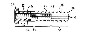
図1に示す器具(例えば、器具30)は、図2〜図5中にさらに詳しく示されている。器具30は、チタンからなるスリーブ32と、適当な生体適合性の材料または適当な金属合金からなるねじ34とからなる。スリーブ32は、シャンク36と、シャンク36の一端に形成された頭部38とからなる。シャンク36は、頭部38に直接隣接するとともにリブの付いた部分42に溶け込む滑らかな部分40を含む。リブの付いた部分42のリブ44は、シャンク36の長手方向の軸と同中心に形成されている。リブ44は、鋸歯状の輪郭の断面を有するように、斜面を有する環状のスロット46によって形成されている。シャンク36の端部は、円錐形の導入部48からなる。
【0016】
軸に平行な4つのスロット50は、90°の円周方向の間隔を置いて、配置されている。スロット50は、導入部48から滑らかな部分40に向って延びており、当該スロット50の形成された部分を4つの区画部に分けている。
【0017】
図3に示されるように、頭部38は、滑らかな部分40の直径よりも有意に大きな幅をもつ六角形の頭部である。頭部38の上には、4つの線状の印52が、90°の間隔で付けられている。4つの印52は、いずれも、隣接するスロット50間の中央に位置する。その結果、図2に示す本発明の器具を扱う外科医は、スリーブの上記4つの区画部の各々が、回転方向のどの位置にあるかを知ることができる。
【0018】
図4から理解されるように、スリーブ32とシャンク36は、完全に貫通した孔54を有する。内側の螺刻部56は、頭部38からシャンク36の約3分の2の地点まで延び、その後、螺刻部56の頂部の直径(tip diameter)とおおよそ一致する直径を有する部分(結合部)58の中に溶け込んでいる。
【0019】
図5中、ねじ34は、六角形の頭部60と、螺刻されたシャンク62とからなる。螺刻されたシャンク62は、スリーブのシャンク36よりも短い。頭部60は、スリーブ32の頭部38よりも有意に小さい。
【0020】
ねじ34が、スリーブ32の中に螺入されると、リブの付いた部分42中の区画部の部分は、外方に放射状に広がる。この状態は、図1に示される。このように、骨片26,28は、孔の壁に対して、区画部によって効果的に押し付けられる。それゆえ、固定によって生じる危険を伴うことなく、早期に移植片を埋め込むことが可能である。
【0021】
適切な準備の後の最初の施術とともに、孔18,20が、移植片22を配置することのできるように、穿設される。孔18,20の直径は、骨片26,28の厚みよりも有意に大きい。まず、外側から移植片22を配置し、図示されていない手段の助けによって、当該移植片22を一時的に締着した後、2つの器具30,32のうちの一つが、導入され、ねじ込み用器具の助けによってねじ込まれる。ねじ込み用器具を伴った器具30の頭部38が、回転できないように保持されているために、頭部38の側に位置するねじ34は、骨片26または28を孔の壁に押し付けることを目的として、リブの付いた部分42を同時に拡開しつつ、スリーブ32の中に螺入され得る。仮に、骨片26,28のうちの一方が、固定されるのであれば、同様に、他方の骨片についても、固定され得る。
【図面の簡単な説明】
【図1】膝に埋め込んだ後の2つの本発明の器具を示す図である。
【図2】本発明の器具を示す側面図である。
【図3】図2中の矢印3の方向から見た本発明の器具を示す図である。
【図4】図2に示す本発明の器具のスリーブを示す縦断面図である。
【図5】図2に示す本発明の器具のねじを示す側面図である。
【符号の説明】
10 大腿骨
12 脛骨
14,16 関節部分
18,20,54 孔
22 膝蓋骨腱移植片
24 靭帯部分
26,28 骨片
30,31 器具
32 スリーブ
34 ねじ
36,62 シャンク
38,60 頭部
40 滑らかな部分
42 リブの付いた部分(凹凸部)
44 リブ
46,50 スロット
48 導入部
52 印
56 螺刻部
58 螺刻されていない部分(結合部)[0001]
BACKGROUND OF THE INVENTION
The present invention relates to a device for securing a crucial ligament transplant in a knee joint.
[0002]
[Prior art]
Implanting a patella tendon bone transplant is an established method of knee ligament surgery for a torn cruciate ligament. In the early weeks after surgery, the intensity of early functional rehabilitation is essentially limited by the fixed graft breaking load. It is known to use a so-called interference screw for fixing. By using the interference screw, the end of the tendon, or the bone fragment connected to the tendon, is fixed in the hole of the appropriate knee joint part with the help of the screw. However, this type of fixation has been shown to cause various problems and complications. Specific examples of these problems include bone block damage, uncontrollable bone fragment displacement, bone fragment fracture, and ligament graft damage. Also, incorrect placement of interference screws has been observed.
[0003]
[Problems to be solved by the invention]
It is an object of the present invention to provide an instrument for fixing a cruciate ligament graft that does not have the above-mentioned problems, can be easily performed, and ensures effective fixation.
[0004]
[Means for Solving the Problems]
The device of the present invention is for fixing a cruciate ligament graft in a knee joint part,
A generally cylindrical sleeve (32) made of a biocompatible metallic material and a screw (34);
The sleeve (32) is circumferentially spaced apart and extends longitudinally from one end of the sleeve (32), at least two slots (50) parallel to the axis, and the sleeve in the region of the slot (50) A concavo-convex portion (42) of the portion, a head portion (38) formed at the other end of the sleeve (32), and an inner threaded portion extending from the head portion (38) to the region of the slot (50) ( 56)
Here, the connecting portion (58) of the hole (54) of the sleeve (32) has a diameter equal to or smaller than the diameter of the top of the inner threaded portion (56), and the screw ( 34) has a threaded shank (62) that can be screwed into the inner threaded portion (56) and a head (60) formed at one end of the shank (62);
Here, the length of the shank (62) is smaller than the length of the sleeve (30).
[0005]
The device of the present invention consists of two parts, specifically a sleeve and a screw. The screw consists of a shank shank and a head provided at the end of the shank. The sleeve and the screw are made of a biocompatible material. The sleeve is preferably manufactured from titanium.
[0006]
The sleeve has a head provided at one end, and at least two slots parallel to the axis that are spaced apart in the circumferential direction and extend from the other end of the sleeve toward the head (longitudinal direction). Including. The sleeve further includes an inner threaded portion into which the shank of the screw is screwed. Since the diameter of the portion of the non-threaded sleeve hole that exists toward the free end of the sleeve is the same as or smaller than the diameter of the inner threaded portion, the thread shank is screwed into the sleeve. The effect is that the sleeve expands at the free end of the sleeve when it enters a non-engraved portion.
[0007]
Roughening is formed on the outside of the sleeve between the slots. Thus, with the aid of the device of the present invention, the bone fragment or patella tendon is itself effective against the walling formed by the boring device already introduced into the joint part from the outside. Can be fastened to.
[0008]
In one embodiment of the present invention, the concavo-convex portion is formed by an annular rib that is concentric with the axis of the sleeve. The ribs can be formed such that their cross-section has a sawtooth-like continuous line profile that has the effect of fixing the implant in the hole particularly effectively.
[0009]
In one form of the present invention, the sleeve has a smooth outer portion between the head and the concavo-convex portion. As is known, the irregularities reduce the strength of the sleeve. On the other hand, the smooth outer part has a greater strength so that the overall strength of the sleeve is very large. The slot may extend into the smooth outer portion, or may be interrupted at the boundary between the uneven portion and the smooth outer portion. Preferably, four such slots are provided with a circumferential spacing of 90 °.
[0010]
In a further embodiment of the invention, the outside of the sleeve head is marked with a fixed positional relationship with respect to the slot. This allows the surgeon to ensure that the expanded portion of the sleeve is effectively engaged with the implant. It is avoided that the area of the slot directly engages the implant, reducing the effectiveness of fixation.
[0011]
The head of the sleeve is preferably polygonal, similar to the head of the screw. The polygonal head of the sleeve serves to prevent the sleeve from rotating when a screw is screwed into the sleeve from the side of the sleeve head. It should be understood that the diameter of the sleeve or the width of the head of the screw is considerably smaller than the width of the head of the sleeve.
[0012]
In a further form of the invention, the length of the sleeve is 26-30 mm, preferably 28 mm. The sleeve has a diameter of 4 to 6 mm, preferably 5 mm, measured at a smooth area close to its head or at the tip of the irregularities.
[0013]
DETAILED DESCRIPTION OF THE INVENTION
Hereinafter, the present invention will be described in more detail with reference to embodiments shown in the drawings.
In FIG. 1, the
[0014]
A
[0015]
The instrument (eg, instrument 30) shown in FIG. 1 is shown in more detail in FIGS. The
[0016]
The four
[0017]
As shown in FIG. 3, the
[0018]
As can be seen from FIG. 4, the
[0019]
In FIG. 5, the
[0020]
As the
[0021]
With the first procedure after proper preparation, the
[Brief description of the drawings]
FIG. 1 shows two inventive devices after implantation in a knee.
FIG. 2 is a side view showing the device of the present invention.
FIG. 3 is a view showing the instrument of the present invention as seen from the direction of
4 is a longitudinal sectional view showing a sleeve of the device of the present invention shown in FIG. 2. FIG.
FIG. 5 is a side view showing a screw of the device of the present invention shown in FIG. 2;
[Explanation of symbols]
10
44
Claims (12)
上記スリーブ(32)が、当該スリーブ(32)の一端から長手方向に軸に平行して延び、且つ円周方向に離れて位置する少なくとも2つのスロット(50)と、該スロット(50)の領域内におけるスリーブ部分に形成された凹凸部(42)と、当該スリーブ(32)の他端に形成された頭部(38)と、該頭部(38)から上記スロット(50)の領域まで延びる内側の螺刻部(56)とを有するものであり、上記スリーブ(32)の孔(54)のうち十字靭帯移植片および膝関節部分との結合部分(58)が、上記内側の螺刻部(56)の先端部分の直径と等しいかあるいはそれよりも小さな直径を有し、
上記ねじ(34)が、上記内側の螺刻部(56)の中にねじ込むことのできる螺刻されたシャンク(62)と、該シャンク(62)の一端に形成された頭部(60)とを有し、
上記シャンク(62)の長さが、上記スリーブ(32)の長さよりも短い器具。 A device for fixing a cruciate ligament graft in a knee joint portion, comprising a generally cylindrical sleeve (32) made of a biocompatible metallic material and a screw (34). ,
The sleeve (32) extends from one end of the sleeve (32) in a longitudinal direction parallel to the axis and is spaced circumferentially; and an area of the slot (50) An uneven portion (42) formed in the sleeve portion inside, a head (38) formed at the other end of the sleeve (32), and extends from the head (38) to the slot (50) region. It is intended to chromatic threaded portion of the inner and (56), coupling portions fraction of the cruciate ligament graft and a knee joint part of the hole (54) of the sleeve (32) (58), threaded in the inner or equal to the diameter of the above end portion of embossing section (56) or than having a smaller diameter,
The screw (34), said inner threaded portion and threaded shank can be screwed into the (56) (62), formed at one end of said shank (62) and the head (60) Have
An instrument in which the length of the shank (62) is shorter than the length of the sleeve (32).
Applications Claiming Priority (2)
| Application Number | Priority Date | Filing Date | Title |
|---|---|---|---|
| DE29815290U DE29815290U1 (en) | 1998-08-26 | 1998-08-26 | Device for anchoring a cruciate ligament graft in the knee joint parts |
| DE29815290:8 | 1998-08-26 |
Publications (2)
| Publication Number | Publication Date |
|---|---|
| JP2000229087A JP2000229087A (en) | 2000-08-22 |
| JP4125447B2 true JP4125447B2 (en) | 2008-07-30 |
Family
ID=8061778
Family Applications (1)
| Application Number | Title | Priority Date | Filing Date |
|---|---|---|---|
| JP23776299A Expired - Lifetime JP4125447B2 (en) | 1998-08-26 | 1999-08-25 | Instrument for securing the cruciate ligament graft in the knee joint |
Country Status (5)
| Country | Link |
|---|---|
| EP (1) | EP0995409B1 (en) |
| JP (1) | JP4125447B2 (en) |
| AU (1) | AU754517B2 (en) |
| CA (1) | CA2280655C (en) |
| DE (2) | DE29815290U1 (en) |
Families Citing this family (69)
| Publication number | Priority date | Publication date | Assignee | Title |
|---|---|---|---|---|
| US6610079B1 (en) | 1999-12-14 | 2003-08-26 | Linvatec Corporation | Fixation system and method |
| US7608092B1 (en) | 2004-02-20 | 2009-10-27 | Biomet Sports Medicince, LLC | Method and apparatus for performing meniscus repair |
| US8361113B2 (en) | 2006-02-03 | 2013-01-29 | Biomet Sports Medicine, Llc | Method and apparatus for coupling soft tissue to a bone |
| US7909851B2 (en) | 2006-02-03 | 2011-03-22 | Biomet Sports Medicine, Llc | Soft tissue repair device and associated methods |
| US9801708B2 (en) | 2004-11-05 | 2017-10-31 | Biomet Sports Medicine, Llc | Method and apparatus for coupling soft tissue to a bone |
| US7857830B2 (en) | 2006-02-03 | 2010-12-28 | Biomet Sports Medicine, Llc | Soft tissue repair and conduit device |
| US7601165B2 (en) | 2006-09-29 | 2009-10-13 | Biomet Sports Medicine, Llc | Method and apparatus for forming a self-locking adjustable suture loop |
| US8088130B2 (en) | 2006-02-03 | 2012-01-03 | Biomet Sports Medicine, Llc | Method and apparatus for coupling soft tissue to a bone |
| US7749250B2 (en) | 2006-02-03 | 2010-07-06 | Biomet Sports Medicine, Llc | Soft tissue repair assembly and associated method |
| US8840645B2 (en) | 2004-11-05 | 2014-09-23 | Biomet Sports Medicine, Llc | Method and apparatus for coupling soft tissue to a bone |
| US9017381B2 (en) | 2007-04-10 | 2015-04-28 | Biomet Sports Medicine, Llc | Adjustable knotless loops |
| US8137382B2 (en) | 2004-11-05 | 2012-03-20 | Biomet Sports Medicine, Llc | Method and apparatus for coupling anatomical features |
| US8118836B2 (en) | 2004-11-05 | 2012-02-21 | Biomet Sports Medicine, Llc | Method and apparatus for coupling soft tissue to a bone |
| US7905903B2 (en) | 2006-02-03 | 2011-03-15 | Biomet Sports Medicine, Llc | Method for tissue fixation |
| US20060189993A1 (en) | 2004-11-09 | 2006-08-24 | Arthrotek, Inc. | Soft tissue conduit device |
| US7905904B2 (en) | 2006-02-03 | 2011-03-15 | Biomet Sports Medicine, Llc | Soft tissue repair device and associated methods |
| US8128658B2 (en) | 2004-11-05 | 2012-03-06 | Biomet Sports Medicine, Llc | Method and apparatus for coupling soft tissue to bone |
| US8303604B2 (en) | 2004-11-05 | 2012-11-06 | Biomet Sports Medicine, Llc | Soft tissue repair device and method |
| US8298262B2 (en) | 2006-02-03 | 2012-10-30 | Biomet Sports Medicine, Llc | Method for tissue fixation |
| US7914539B2 (en) | 2004-11-09 | 2011-03-29 | Biomet Sports Medicine, Llc | Tissue fixation device |
| US8034090B2 (en) | 2004-11-09 | 2011-10-11 | Biomet Sports Medicine, Llc | Tissue fixation device |
| US8998949B2 (en) | 2004-11-09 | 2015-04-07 | Biomet Sports Medicine, Llc | Soft tissue conduit device |
| EP1868527A4 (en) * | 2005-03-17 | 2009-12-30 | Active Implants Corp | Implant devices |
| US11259792B2 (en) | 2006-02-03 | 2022-03-01 | Biomet Sports Medicine, Llc | Method and apparatus for coupling anatomical features |
| US7959650B2 (en) | 2006-09-29 | 2011-06-14 | Biomet Sports Medicine, Llc | Adjustable knotless loops |
| US9538998B2 (en) | 2006-02-03 | 2017-01-10 | Biomet Sports Medicine, Llc | Method and apparatus for fracture fixation |
| US8801783B2 (en) | 2006-09-29 | 2014-08-12 | Biomet Sports Medicine, Llc | Prosthetic ligament system for knee joint |
| US8574235B2 (en) | 2006-02-03 | 2013-11-05 | Biomet Sports Medicine, Llc | Method for trochanteric reattachment |
| US8597327B2 (en) | 2006-02-03 | 2013-12-03 | Biomet Manufacturing, Llc | Method and apparatus for sternal closure |
| US8251998B2 (en) | 2006-08-16 | 2012-08-28 | Biomet Sports Medicine, Llc | Chondral defect repair |
| US9271713B2 (en) | 2006-02-03 | 2016-03-01 | Biomet Sports Medicine, Llc | Method and apparatus for tensioning a suture |
| US8652171B2 (en) | 2006-02-03 | 2014-02-18 | Biomet Sports Medicine, Llc | Method and apparatus for soft tissue fixation |
| US8968364B2 (en) | 2006-02-03 | 2015-03-03 | Biomet Sports Medicine, Llc | Method and apparatus for fixation of an ACL graft |
| US9468433B2 (en) | 2006-02-03 | 2016-10-18 | Biomet Sports Medicine, Llc | Method and apparatus for forming a self-locking adjustable loop |
| US10517587B2 (en) | 2006-02-03 | 2019-12-31 | Biomet Sports Medicine, Llc | Method and apparatus for forming a self-locking adjustable loop |
| US8506597B2 (en) | 2011-10-25 | 2013-08-13 | Biomet Sports Medicine, Llc | Method and apparatus for interosseous membrane reconstruction |
| US9078644B2 (en) | 2006-09-29 | 2015-07-14 | Biomet Sports Medicine, Llc | Fracture fixation device |
| US9149267B2 (en) | 2006-02-03 | 2015-10-06 | Biomet Sports Medicine, Llc | Method and apparatus for coupling soft tissue to a bone |
| US8562645B2 (en) | 2006-09-29 | 2013-10-22 | Biomet Sports Medicine, Llc | Method and apparatus for forming a self-locking adjustable loop |
| US8771352B2 (en) | 2011-05-17 | 2014-07-08 | Biomet Sports Medicine, Llc | Method and apparatus for tibial fixation of an ACL graft |
| US8652172B2 (en) | 2006-02-03 | 2014-02-18 | Biomet Sports Medicine, Llc | Flexible anchors for tissue fixation |
| US11311287B2 (en) | 2006-02-03 | 2022-04-26 | Biomet Sports Medicine, Llc | Method for tissue fixation |
| US8562647B2 (en) | 2006-09-29 | 2013-10-22 | Biomet Sports Medicine, Llc | Method and apparatus for securing soft tissue to bone |
| EP2001405B1 (en) * | 2006-03-20 | 2015-11-18 | Cayenne Medical, Inc. | Systems for tendon fixation |
| US11259794B2 (en) | 2006-09-29 | 2022-03-01 | Biomet Sports Medicine, Llc | Method for implanting soft tissue |
| US9918826B2 (en) | 2006-09-29 | 2018-03-20 | Biomet Sports Medicine, Llc | Scaffold for spring ligament repair |
| US8500818B2 (en) | 2006-09-29 | 2013-08-06 | Biomet Manufacturing, Llc | Knee prosthesis assembly with ligament link |
| US8672969B2 (en) | 2006-09-29 | 2014-03-18 | Biomet Sports Medicine, Llc | Fracture fixation device |
| EP2086433B1 (en) | 2006-10-24 | 2015-10-21 | Cayenne Medical, Inc. | Tendon Anchor |
| CN102098984B (en) | 2008-05-14 | 2017-06-23 | 史密夫和内修有限公司 | Anchoring of tendon of biceps prosthetic device under arthroscope |
| WO2010077591A2 (en) | 2008-12-09 | 2010-07-08 | Smith & Nephew, Inc. | Tissue repair assembly |
| US8858606B2 (en) | 2008-12-09 | 2014-10-14 | Smith & Nephew, Inc. | Tissue repair assembly |
| US8343227B2 (en) | 2009-05-28 | 2013-01-01 | Biomet Manufacturing Corp. | Knee prosthesis assembly with ligament link |
| US9301846B2 (en) * | 2010-08-13 | 2016-04-05 | Smith & Nephew, Inc. | Instruments for knee placement |
| US8679160B2 (en) * | 2010-09-28 | 2014-03-25 | Facet-Link Inc. | Lamina implant set |
| US9357991B2 (en) | 2011-11-03 | 2016-06-07 | Biomet Sports Medicine, Llc | Method and apparatus for stitching tendons |
| US9357992B2 (en) | 2011-11-10 | 2016-06-07 | Biomet Sports Medicine, Llc | Method for coupling soft tissue to a bone |
| US9370350B2 (en) | 2011-11-10 | 2016-06-21 | Biomet Sports Medicine, Llc | Apparatus for coupling soft tissue to a bone |
| US9381013B2 (en) | 2011-11-10 | 2016-07-05 | Biomet Sports Medicine, Llc | Method for coupling soft tissue to a bone |
| US9259217B2 (en) | 2012-01-03 | 2016-02-16 | Biomet Manufacturing, Llc | Suture Button |
| US9757119B2 (en) | 2013-03-08 | 2017-09-12 | Biomet Sports Medicine, Llc | Visual aid for identifying suture limbs arthroscopically |
| US9918827B2 (en) | 2013-03-14 | 2018-03-20 | Biomet Sports Medicine, Llc | Scaffold for spring ligament repair |
| US10136886B2 (en) | 2013-12-20 | 2018-11-27 | Biomet Sports Medicine, Llc | Knotless soft tissue devices and techniques |
| US9615822B2 (en) | 2014-05-30 | 2017-04-11 | Biomet Sports Medicine, Llc | Insertion tools and method for soft anchor |
| US9700291B2 (en) | 2014-06-03 | 2017-07-11 | Biomet Sports Medicine, Llc | Capsule retractor |
| US10039543B2 (en) | 2014-08-22 | 2018-08-07 | Biomet Sports Medicine, Llc | Non-sliding soft anchor |
| US9955980B2 (en) | 2015-02-24 | 2018-05-01 | Biomet Sports Medicine, Llc | Anatomic soft tissue repair |
| US9974534B2 (en) | 2015-03-31 | 2018-05-22 | Biomet Sports Medicine, Llc | Suture anchor with soft anchor of electrospun fibers |
| CN112179286B (en) * | 2020-08-18 | 2021-12-21 | 江苏瑞尔隆盛叶轮科技有限公司 | Clamp special for GOM three-dimensional optical scanner |
Family Cites Families (14)
| Publication number | Priority date | Publication date | Assignee | Title |
|---|---|---|---|---|
| US2490364A (en) * | 1948-02-27 | 1949-12-06 | Herman H Livingston | Bone pin |
| US3953896A (en) | 1974-09-06 | 1976-05-04 | Richards Manufacturing Company, Inc. | Prosthetic ligament |
| US4744793A (en) | 1985-09-06 | 1988-05-17 | Zimmer, Inc. | Prosthetic ligament connection assembly |
| US4708132A (en) | 1986-01-24 | 1987-11-24 | Pfizer-Hospital Products Group, Inc. | Fixation device for a ligament or tendon prosthesis |
| DE3706520A1 (en) | 1987-02-28 | 1988-09-08 | Kernforschungsz Karlsruhe | Method and aid for application of a substitute for the cruciate ligaments |
| DE3711465A1 (en) | 1987-04-04 | 1988-10-13 | Kernforschungsz Karlsruhe | DEVICE FOR IN VIVO FASTENING OF A CROSSBAND REPLACEMENT ON THE BONE |
| CH674705A5 (en) * | 1988-04-27 | 1990-07-13 | Sulzer Ag | |
| DE3840474A1 (en) | 1988-12-01 | 1990-06-07 | Lieke Michael | Knee joint endoprosthesis and knee joint endoprosthetic components |
| FR2671717A1 (en) * | 1991-01-17 | 1992-07-24 | Asa Laboratoires Prothaid | Expansion bolt for the fixation of a ligament prosthesis on the cortical wall of a bone |
| US5720753A (en) * | 1991-03-22 | 1998-02-24 | United States Surgical Corporation | Orthopedic fastener |
| FR2696925B3 (en) * | 1992-10-19 | 1994-12-23 | Sanouiller Jean Louis | Orthopedic surgery kit for anchoring the bone part of a ligament in a bone tunnel. |
| US5489210A (en) * | 1994-05-13 | 1996-02-06 | Hanosh; Frederick N. | Expanding dental implant and method for its use |
| FR2740324B1 (en) * | 1995-10-27 | 1997-12-26 | Bgci | LIGAMENTARY ANCHORING DEVICE |
| US5702462A (en) | 1996-01-24 | 1997-12-30 | Oberlander; Michael | Method of meniscal repair |
-
1998
- 1998-08-26 DE DE29815290U patent/DE29815290U1/en not_active Expired - Lifetime
-
1999
- 1999-08-17 DE DE1999638328 patent/DE69938328T2/en not_active Expired - Lifetime
- 1999-08-17 EP EP19990116209 patent/EP0995409B1/en not_active Expired - Lifetime
- 1999-08-24 AU AU44696/99A patent/AU754517B2/en not_active Expired
- 1999-08-25 CA CA 2280655 patent/CA2280655C/en not_active Expired - Lifetime
- 1999-08-25 JP JP23776299A patent/JP4125447B2/en not_active Expired - Lifetime
Also Published As
| Publication number | Publication date |
|---|---|
| AU4469699A (en) | 2000-03-09 |
| AU754517B2 (en) | 2002-11-21 |
| DE69938328D1 (en) | 2008-04-24 |
| DE69938328T2 (en) | 2009-07-09 |
| CA2280655C (en) | 2007-10-30 |
| DE29815290U1 (en) | 2000-01-05 |
| EP0995409B1 (en) | 2008-03-12 |
| JP2000229087A (en) | 2000-08-22 |
| CA2280655A1 (en) | 2000-02-26 |
| EP0995409A1 (en) | 2000-04-26 |
Similar Documents
| Publication | Publication Date | Title |
|---|---|---|
| JP4125447B2 (en) | Instrument for securing the cruciate ligament graft in the knee joint | |
| EP1235524B1 (en) | Orthopaedic ligament fixation system | |
| US4950270A (en) | Cannulated self-tapping bone screw | |
| US5951560A (en) | Wedge orthopedic screw | |
| US6187008B1 (en) | Device for temporarily fixing bones | |
| AU767446B2 (en) | Improved strength fixation device | |
| US5391171A (en) | Pin-locked cannulated screwdriver | |
| JP3925942B2 (en) | Graft fixture | |
| US7235078B2 (en) | Protective devices for use with angled interference screws | |
| US5776194A (en) | Intermedullary rod apparatus and methods of repairing proximal humerus fractures | |
| JP4255212B2 (en) | Surgical blind rivet with closure element | |
| FI111330B (en) | Anchorage elements that support a prosthesis or joint mechanism intended for reconstructed joints | |
| JP2607876Y2 (en) | Surgical screw | |
| US6139565A (en) | Suture anchor assembly | |
| US8241287B2 (en) | Implant for osteosynthesis | |
| US5201733A (en) | Method and apparatus for internal fixation of fractures | |
| US20090192512A1 (en) | Bone nail | |
| US20040006349A1 (en) | Apparatus and method for attaching a graft ligament to a bone | |
| EP1136046A2 (en) | Cementless glenoid component | |
| US20040176767A1 (en) | Fixation augmentation device and related techniques | |
| KR20080074895A (en) | Orthopedic rod with locking aperture | |
| US7569055B2 (en) | Osteosynthetic aid | |
| US20050216012A1 (en) | Bone pin | |
| WO2009132341A1 (en) | Fixation device and method for soft tissue grafts | |
| AU770724B2 (en) | Orthopaedic ligament fixation system |
Legal Events
| Date | Code | Title | Description |
|---|---|---|---|
| A621 | Written request for application examination |
Free format text: JAPANESE INTERMEDIATE CODE: A621 Effective date: 20060821 |
|
| A131 | Notification of reasons for refusal |
Free format text: JAPANESE INTERMEDIATE CODE: A131 Effective date: 20071012 |
|
| A601 | Written request for extension of time |
Free format text: JAPANESE INTERMEDIATE CODE: A601 Effective date: 20080111 |
|
| A602 | Written permission of extension of time |
Free format text: JAPANESE INTERMEDIATE CODE: A602 Effective date: 20080117 |
|
| A521 | Written amendment |
Free format text: JAPANESE INTERMEDIATE CODE: A523 Effective date: 20080212 |
|
| TRDD | Decision of grant or rejection written | ||
| A01 | Written decision to grant a patent or to grant a registration (utility model) |
Free format text: JAPANESE INTERMEDIATE CODE: A01 Effective date: 20080411 |
|
| A01 | Written decision to grant a patent or to grant a registration (utility model) |
Free format text: JAPANESE INTERMEDIATE CODE: A01 |
|
| A61 | First payment of annual fees (during grant procedure) |
Free format text: JAPANESE INTERMEDIATE CODE: A61 Effective date: 20080508 |
|
| R150 | Certificate of patent or registration of utility model |
Ref document number: 4125447 Country of ref document: JP Free format text: JAPANESE INTERMEDIATE CODE: R150 Free format text: JAPANESE INTERMEDIATE CODE: R150 |
|
| FPAY | Renewal fee payment (event date is renewal date of database) |
Free format text: PAYMENT UNTIL: 20110516 Year of fee payment: 3 |
|
| FPAY | Renewal fee payment (event date is renewal date of database) |
Free format text: PAYMENT UNTIL: 20120516 Year of fee payment: 4 |
|
| R250 | Receipt of annual fees |
Free format text: JAPANESE INTERMEDIATE CODE: R250 |
|
| FPAY | Renewal fee payment (event date is renewal date of database) |
Free format text: PAYMENT UNTIL: 20130516 Year of fee payment: 5 |
|
| R250 | Receipt of annual fees |
Free format text: JAPANESE INTERMEDIATE CODE: R250 |
|
| FPAY | Renewal fee payment (event date is renewal date of database) |
Free format text: PAYMENT UNTIL: 20140516 Year of fee payment: 6 |
|
| R250 | Receipt of annual fees |
Free format text: JAPANESE INTERMEDIATE CODE: R250 |
|
| R250 | Receipt of annual fees |
Free format text: JAPANESE INTERMEDIATE CODE: R250 |
|
| R250 | Receipt of annual fees |
Free format text: JAPANESE INTERMEDIATE CODE: R250 |
|
| R250 | Receipt of annual fees |
Free format text: JAPANESE INTERMEDIATE CODE: R250 |
|
| R250 | Receipt of annual fees |
Free format text: JAPANESE INTERMEDIATE CODE: R250 |
|
| S111 | Request for change of ownership or part of ownership |
Free format text: JAPANESE INTERMEDIATE CODE: R313113 |
|
| R350 | Written notification of registration of transfer |
Free format text: JAPANESE INTERMEDIATE CODE: R350 |
|
| R250 | Receipt of annual fees |
Free format text: JAPANESE INTERMEDIATE CODE: R250 |
|
| R250 | Receipt of annual fees |
Free format text: JAPANESE INTERMEDIATE CODE: R250 |
|
| EXPY | Cancellation because of completion of term |