JP4125268B2 - Yarn feeder of yarn feeding device in flat knitting machine - Google Patents
Yarn feeder of yarn feeding device in flat knitting machine Download PDFInfo
- Publication number
- JP4125268B2 JP4125268B2 JP2004200780A JP2004200780A JP4125268B2 JP 4125268 B2 JP4125268 B2 JP 4125268B2 JP 2004200780 A JP2004200780 A JP 2004200780A JP 2004200780 A JP2004200780 A JP 2004200780A JP 4125268 B2 JP4125268 B2 JP 4125268B2
- Authority
- JP
- Japan
- Prior art keywords
- yarn
- yarn feeder
- feeder
- knitting
- yarn feeding
- Prior art date
- Legal status (The legal status is an assumption and is not a legal conclusion. Google has not performed a legal analysis and makes no representation as to the accuracy of the status listed.)
- Expired - Fee Related
Links
- 238000009940 knitting Methods 0.000 title claims description 68
- 230000007935 neutral effect Effects 0.000 claims description 27
- 230000010355 oscillation Effects 0.000 claims 1
- 239000004744 fabric Substances 0.000 description 9
- 230000006835 compression Effects 0.000 description 3
- 238000007906 compression Methods 0.000 description 3
- 230000001174 ascending effect Effects 0.000 description 2
- 230000005540 biological transmission Effects 0.000 description 2
- 230000000630 rising effect Effects 0.000 description 2
- 230000004308 accommodation Effects 0.000 description 1
- 238000013459 approach Methods 0.000 description 1
- 230000000881 depressing effect Effects 0.000 description 1
- 230000000694 effects Effects 0.000 description 1
- 230000001105 regulatory effect Effects 0.000 description 1
- 239000011435 rock Substances 0.000 description 1
Images


Classifications
-
- D—TEXTILES; PAPER
- D04—BRAIDING; LACE-MAKING; KNITTING; TRIMMINGS; NON-WOVEN FABRICS
- D04B—KNITTING
- D04B15/00—Details of, or auxiliary devices incorporated in, weft knitting machines, restricted to machines of this kind
- D04B15/38—Devices for supplying, feeding, or guiding threads to needles
- D04B15/54—Thread guides
- D04B15/56—Thread guides for flat-bed knitting machines
-
- D—TEXTILES; PAPER
- D04—BRAIDING; LACE-MAKING; KNITTING; TRIMMINGS; NON-WOVEN FABRICS
- D04B—KNITTING
- D04B15/00—Details of, or auxiliary devices incorporated in, weft knitting machines, restricted to machines of this kind
- D04B15/38—Devices for supplying, feeding, or guiding threads to needles
- D04B15/54—Thread guides
-
- D—TEXTILES; PAPER
- D04—BRAIDING; LACE-MAKING; KNITTING; TRIMMINGS; NON-WOVEN FABRICS
- D04B—KNITTING
- D04B7/00—Flat-bed knitting machines with independently-movable needles
- D04B7/24—Flat-bed knitting machines with independently-movable needles for producing patterned fabrics
- D04B7/26—Flat-bed knitting machines with independently-movable needles for producing patterned fabrics with colour patterns
Description
本発明は編地端部やインターシャ編地等の柄編みにおける柄切り換え部分でのヤーンフィーダの待機位置で給糸口を編地編成領域外に切り換えられるようにした横編機における給糸装置のヤーンフィーダに関するものである。 The present invention relates to a yarn feeding device in a flat knitting machine in which a yarn feeder can be switched out of a knitted fabric knitting region at a standby position of a yarn feeder at a pattern switching portion in a pattern knitting such as a knitted fabric end or intarsia knitted fabric. It relates to yarn feeders.
編地を編成するためにキャリッジと連動してニードルベッドの編み針に給糸していたヤーンフィーダはその給糸口が編成領域の外方の待機位置に置かれる。
この時、ヤーンフィーダが隣接する編成領域との境界を越えて大きく移動すればするほどヤーンフィーダから編地に延びる編糸の位置が下がり、編糸を編み針のフックに確実に捉えることができるようすることができる。
一方、インターシャ編では、ヤーンフィーダが隣接する編成領域との境界を越えた位置で連行手段から開放される。
したがってこうしたものでは、隣接する編成領域内で停止したヤーンフィーダから編地に渡る編糸が次の編成領域の編成の邪魔になる。そこで、ヤーンフィーダの揺動量を大きくすることなく、実質的に揺動量を大きくしたのと同じ効果を得られるようにする為に、フィーダケースには給糸口の位置を切り換え揺動させる切り換え機構を設け、切り換え機構は、連行手段と協働して給糸口の揺動方向及び高さ位置を切り換え操作する押し込み操作部を有するヤーンフィーダを先に提案している。(特許文献1)
特許文献1 国際公開WO02−079556
The yarn feeder that has fed yarns to the knitting needles of the needle bed in conjunction with the carriage to knit the knitted fabric is placed at a standby position outside the knitting region.
At this time, as the yarn feeder moves greatly beyond the boundary with the adjacent knitting region, the position of the knitting yarn extending from the yarn feeder to the knitted fabric is lowered, so that the knitting yarn can be reliably caught on the hook of the knitting needle. can do.
On the other hand, in the intarsia knitting, the yarn feeder is released from the entrainment means at a position beyond the boundary with the adjacent knitting region.
Therefore, in such a case, the knitting yarn from the yarn feeder stopped in the adjacent knitting area to the knitted fabric interferes with the knitting of the next knitting area. Therefore, in order to obtain the same effect as increasing the swinging amount without increasing the swinging amount of the yarn feeder, the feeder case has a switching mechanism for switching and swinging the position of the yarn feeder. The provision and switching mechanism has previously proposed a yarn feeder having a push-in operation portion for switching the swing direction and height position of the yarn feeder in cooperation with the entraining means. (Patent Document 1)
Patent Document 1 International Publication WO02-079556
本発明の出願人による先の提案では、ヤーンフィーダの給糸口が待機位置で左または右に大きく揺動するために、編成領域の端の編目から引き出されている編糸が引っ張られることから、当該編成領域の端の編目が詰まり、均一な編目の形成が難しくなってしまう虞があった。
本発明は上記問題点に鑑み提案されたもので、生産性が高く、ヤーンフィーダを大型化することなく、生産性の高い編目のそろった編地を編成することのできる横編機の給糸装置におけるヤーンフィーダを提供することを目的とするものである。
In the previous proposal by the applicant of the present invention, since the yarn feeder of the yarn feeder largely swings to the left or right at the standby position, the knitting yarn drawn from the stitches at the end of the knitting region is pulled. There is a possibility that the stitches at the ends of the knitting region are clogged and it becomes difficult to form uniform stitches.
The present invention has been proposed in view of the above-described problems, and has a high productivity, and the yarn feeding of a flat knitting machine capable of knitting a high-productivity knitted fabric without increasing the size of the yarn feeder. An object of the present invention is to provide a yarn feeder in an apparatus.
上記目的を達成する為に本発明にかかる横編機の給糸装置におけるヤーンフィーダは、ニードルベッドの上部に配設された糸道レールに複数のヤーンフィーダを摺動可能に係合するとともに、連行手段により選択的に連行可能に構成され、連行手段の作動に連動して給糸桿の下端部に設けられた給糸口を給糸位置と待機位置とに切り換え揺動させる切り換え機構を設け、切り換え機構は連行手段で選択されたヤーンフィーダが停止状態から給糸連行されるまでの間に切り換え機構が操作され、給糸口を待機位置から給糸位置に切り換え操作されるとともに、給糸後の給糸口の待機位置への揺動方向を設定し、給糸後の連行手段の選択解除動作に連動して給糸口を給糸位置から待機位置に揺動切り換え可能に構成した横編機のヤーンフィーダにおいて、連行手段に連繋して操作され、給糸口が垂直姿勢で給糸位置より上昇した中立位置を保持するための中立位置保持機構を設け、切り換え機構は揺動可能に枢支された選択レバーを有し、該選択レバーに給糸桿の揺動方向を設定する二つの傾斜面と、両傾斜面の中間部分に給糸桿を垂直状態の中立位置に受け止める受け部を形成し、中立位置で受け部が給糸桿の上端に対面するように選択レバーを操作する操作具を設けて中立保持機構を形成するとともに、略T字状に形成された選択レバーの側端寄り部分を上方に押し上げ揺動する1対のリンクで前記操作具を構成したことを最も主要な特徴とする。 In order to achieve the above object, a yarn feeder in a yarn feeding device of a flat knitting machine according to the present invention slidably engages a plurality of yarn feeders with a yarn path rail disposed on an upper portion of a needle bed, Provided with a switching mechanism that is selectively movable by the entraining means, and that switches and swings the yarn feeder provided at the lower end of the yarn feeder to the yarn feeding position and the standby position in conjunction with the operation of the entraining means, The switching mechanism is operated until the yarn feeder selected by the entraining means is stopped from the stopped state to the yarn feeding, and the yarn feeder is switched from the standby position to the yarn feeding position. Yarn of a flat knitting machine configured to set the swing direction of the yarn feeder to the standby position and to switch the yarn feeder from the yarn feed position to the standby position in conjunction with the selection release operation of the entraining means after yarn feeding To feeder There it is operated in tandem to entraining means, the neutral position holding mechanism for the yarn feeder holds elevated neutral position from the yarn feeding position in a vertical posture provided, switching mechanism is swingably pivoted selection lever Two inclined surfaces for setting the swing direction of the yarn feeder to the selection lever, and a receiving portion for receiving the yarn feeder at a neutral position in a vertical state at an intermediate portion between the two inclined surfaces. In addition, an operation tool for operating the selection lever is provided so that the receiving portion faces the upper end of the yarn feeder to form a neutral holding mechanism, and a portion near the side end of the selection lever formed in a substantially T shape is directed upward. The most important feature is that the operation tool is constituted by a pair of links that push up and swing .
また、切り換え機構は揺動可能に枢支された選択レバーを有し、該選択レバーに給糸桿の揺動方向を設定する二つの傾斜面と、両傾斜面の中間部分に給糸桿を垂直状態の中立位置に受け止める受け部を形成するとともに、中立位置で受け部が給糸桿の上端に対面するように選択レバーを操作する操作具を設けて中立保持機構を形成したことや、操作具が、略T字状に形成された選択レバーの側端寄り部分を上方に押し上げるリンクで構成したこと、さらに、給糸桿がいずれか一方の傾斜面および受け部で設定された姿勢を弾性保持する保持部材を操作レバーに設けたことも特徴とするものである。 The switching mechanism has a selection lever pivotally supported. The selection lever has two inclined surfaces for setting the swinging direction of the yarn feeder, and a yarn feeder at an intermediate portion between the two inclined surfaces. A neutral holding mechanism is formed by forming a receiving part that is received at the neutral position in the vertical state and an operating tool that operates the selection lever so that the receiving part faces the upper end of the yarn feeder at the neutral position. The tool is composed of a link that pushes upward a portion near the side end of the selection lever formed in a substantially T shape, and the yarn feeder is elastic in the posture set by one of the inclined surfaces and the receiving portion. The holding member to hold | maintain is also provided in the operation lever.
本発明によれば、給糸後の連行手段の選択解除動作に連動して給糸口を給糸位置から待機位置に切り換え可能に構成した切り換え機構に、待機位置で給糸口を中立位置に保持する中立位置保持機構を設けるようにしてあるので、待機位置でのヤーンフィーダの給糸口が先の提案のように待機位置で左または右に大きく揺動することをなくせ、編成領域の端の編目から引き出されている編糸が強く引っ張られることがない。これにより、当該編成領域の端の編目が詰まることがなく、均一な編目の品質の高い編地を形成することができる利点がある。 According to the present invention, the yarn feeder is held at the neutral position at the standby position by the switching mechanism configured to be able to switch the yarn feeder from the yarn feeding position to the standby position in conjunction with the selection release operation of the entraining means after yarn feeding. Since the neutral position holding mechanism is provided, the yarn feeder of the yarn feeder at the standby position can be prevented from swinging greatly to the left or right at the standby position as previously proposed. The drawn knitting yarn is not pulled strongly. Thereby, there is an advantage that the stitches at the ends of the knitting region are not clogged and a knitted fabric having a uniform stitch quality can be formed.
また、ヤーンフィーダが直立状態の待機位置では給糸口の位置が高くならないことから、編成領域の端目での目移しや増し目時の編糸を編針の背面に確実に回すことができる利点もある。
さらに、従来のようにヤーンフィーダを編成領域外に大きく摺動させなくても済み、ヤーンフィーダの摺動距離が短くしてその分は生産性を向上させることができる利点もある。
In addition, since the position of the yarn feeder does not increase at the standby position where the yarn feeder is in the upright state, there is also an advantage that the knitting yarn at the end of the knitting region can be reliably turned to the back of the knitting needle. is there.
Furthermore, there is an advantage that the yarn feeder does not have to be slid largely outside the knitting area as in the conventional case, and the sliding distance of the yarn feeder is shortened, and the productivity can be improved correspondingly.
加えて、切り換え機構に、ヤーンフィーダの待機位置で給糸口を編針に近接する低い中立位置に保持する中立位置保持機構を設けるだけで、ヤーンフィーダを大型化するのを防止して、コンパクトにすることができる利点もある。 In addition, the switching mechanism is provided with a neutral position holding mechanism that holds the yarn feeder at a low neutral position close to the knitting needle at the standby position of the yarn feeder, thereby preventing the yarn feeder from becoming large and making it compact. There is also an advantage that can be done.
以下本発明にかかる横編機の給糸装置にかかる実施の一形態を図面に基づいて説明する。
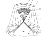
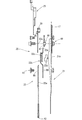
図1は、本発明のヤーンフィーダを備えた給糸装置を有する横編機の側面図であって、図中符号1は横編機を全体的に示し、符号2は給糸装置を示す。
この横編機1は、前後一対のニードルベッド3を”ハ”の字形にその先端を対峙させた状態でフレーム4に配設し、それぞれのニードルベッド3には、複数の編針5を進退操作可能に並設してある。
ニードルベッド3の上面にはキャリッジ6がベルト駆動手段(図示せず)により往復走行可能に配設されており、キャリッジ6には図に示すような編成カム7が設けられており、この編成カム7で編針5のバット48が操作されて編針5の進退操作が行われる。
An embodiment of a yarn feeding device for a flat knitting machine according to the present invention will be described below with reference to the drawings.
FIG. 1 is a side view of a flat knitting machine having a yarn feeder equipped with a yarn feeder according to the present invention. In the figure, reference numeral 1 indicates the whole flat knitting machine, and
The flat knitting machine 1 has a pair of front and
A
キャリッジ6には、前後のニードルベッド3を跨いで一体的に連結するゲートアーム(摺動駆動機構)8が設けられており、ゲートアーム8にはヤーンフィーダ9を連行する連行手段10及びヤーンフィーダ9の給糸口12を編針5・5の先端の近傍位置にまで下降させる押し下げ手段13が搭載されている。
ニードルベッド3の上方には、ニードルベッド3の長手方向に沿って4本の糸道レール11が、ニードルベッド3に並設された編針5の先端部近傍を中心としてニードルベッド3前後方向に扇状に配置されている。
上記連行手段10は、制御装置(図示せず)からの出力信号により、突出及び退入制御されるソレノイドの出力軸の動きを図2に示すように、連行ピン14に伝える伝動桿15を備え、連行ピン14は、スプリング16により下降付勢されており、連行ピン14を各ヤーンフィーダ9のフィーダケース17の上端中央寄り部分に左右一対の揺動片18に形成された係合部19に係合させてヤーンフィーダ9を連行するようになっている(図3参照)。
The
Above the
The entrainment means 10 includes a
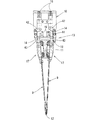
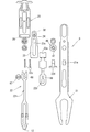
ヤーンフィーダ9は、糸道レール11に摺動可能に支持されるフィーダケース17と、フィーダケース17から下端に給糸口12が設けられた給糸桿20と、この給糸桿20を上下方向に案内する給糸桿ガイド21とを垂下するとともに、待機位置で給糸口12を中立位置に保持する中立位置保持機構が形成されており、給糸桿ガイド21はその上寄り部分の枢支部でフィーダケース17に揺動可能に枢支されている。
給糸桿20は、左右の側縁部が給糸桿ガイド21に昇降摺動可能に支持された細長い板状の下部プレート22と、下部プレート22の上端部分に、下端部が接離して連係する中間プレート23と、下端部が中間プレート23の上部後面に突出させた押し下げローラ24を介して連結された上部プレート25とで形成されており、押し下げローラ24は、上部プレート25の下端部に形成された横長の長孔26に嵌合させてある。
上部プレート25の中間部分には、中間プレート23及び下部プレート22を介して給糸口12を上昇付勢するためのコイルスプリング27がフィーダケース17のバネ受け部28との間に亙って装着されている。
The
The
A
上記下部プレート22は図3及び図4に示すように、給糸口形成部材22aと、給糸口形成部材22aの上部で給糸桿ガイド21との間に配設されたバネ収納部材22bと、バネ収納部材22bに収納された圧縮バネ22cと、給糸桿ガイド21の係合穴21aに係合し、前記圧縮バネ(付勢手段)22cの下端部を受け止める受け具22dとを備え、バネ収納部材22bの上端部は後述する規制具46に当接する当接部22eが形成されており、圧縮バネ22cにより下部プレート22が上方に引き上げ付勢されている。
当接部22eが当接する規制具46は、中間プレート23に形成された摺動用長孔23aを通して給糸桿ガイド21とともにフィーダケース17に共締め固定された駒状部材47で形成されている。
また、下部プレート22の給糸口形成部材22aの上端の長孔65と、バネ収納部材22bの上端部に形成された孔66とをボルト・ナット等の固定具67で連結する場合には、この固定具67を緩めて下部プレート22の位置を調整することにより給糸口12の高さ位置の調整を行うことができるようになっている(図3及び図4参照)。
また、中間プレート23の上端部前面には、給糸口12の姿勢を切り換える切り換え機構29の切り換え用ローラ30を突出させてある。
切り換え機構29は、上記切り換え用ローラ30とこの切り換え用ローラ30の揺動を規制するためにフィーダケース17に穿設された規制孔31と、規制孔31の後面側に配設された選択レバー32とを備えてなる。
As shown in FIGS. 3 and 4, the
The restricting
When the
Further, a
The
上記規制孔31は図3および図4に示すように、中央とその上部の左右に切り換え用ローラ30が嵌合する部分を有する略三つ葉形に形成されている。
この規制孔31に臨む切り換え用ローラ30の上昇方向を設定する選択レバー32は、上端部32aが緩やかなV形に形成された略T形に形成されており、その中央の枢支部32bがフィーダケース17に枢支されるとともに、上端部32aの中央部分から垂下された下端部には切り換え用ローラ30の上昇方向を振り分けるために、その下端部分の左右の側面部分に傾斜面34・34が形成された略矢印形に形成されるとともに、両傾斜面34・34の中間部分には中立姿勢で切り換え用ローラ30を受けるローラ受け部35が形成されている。
As shown in FIGS. 3 and 4, the
The selection lever 32 for setting the rising direction of the
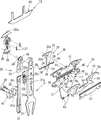
また二つの傾斜面34・34及びローラ受け部35からなる略矢印形部分の上部には選択レバー32の切り換え姿勢を保持する為の保持手段36が設けられている。
この保持手段36は、矢印形部分の上部から左右に髭状の弾性部37を延出し、この弾性部37の先端寄り部分を曲成して抱持部38・39をそれぞれ形成するとともに、選択レバー32が右または左に操作された時にいずれか一方の抱持部38が嵌合し、選択レバー32が中立位置の時には両抱持部39・39が嵌合する嵌合用突起40をフィーダケース17の裏面に設けて構成されている。
A holding means 36 for holding the switching posture of the
The holding means 36 extends from the upper part of the arrow-shaped part to the left and right with a hook-shaped
待機位置で選択レバー32を直立する姿勢にして給糸口12を編針5に近接する低い中立位置に保持する中立位置保持機構50は、図4に示すようにフィーダケース17の上端部分に穿設された枢支部51・51と、この枢支部51・51に回動部52・52が揺動可能に枢支された1対のリンク53が設けられている。
この1対のリンク53は、先端部分同士がフィーダケース17の中央部分で係合する係合片54を水平方向に形成し、互いに対面する側面部分からは選択レバー32の上端部分32aを下方から押し上げてこの選択レバー32を中立位置に操作する操作用突起55が形成されており、上部には操作片56が回動部52から左右方向に形成されている。
この操作片56は連行ピン14で揺動操作されるもので、回動部52から左右方向に形成され、その上面が係合片54側で低くなる傾斜面状に形成されるとともに、外側端部が斜め下向きの傾斜状に形成されている。尚、図中符号57はリンク53の抜け止め用のプレートである。
A neutral
The pair of
The
また、上記給糸桿20を押し下げる押し下げ手段13は、一端が上記連行ピン14の中間高さ位置に連結された連結プレート42と、この連結プレート42の他端をカムプレート43の上端部に連結することにより、連行ピン14の上下動に連動してカムプレート43が揺動枢支ピン44を中心として前後に揺動されるように形成されている。
このカムプレート43の中寄り部分に上記連行ピン14が糸道レール11側に設けられている。
The push-down means 13 for pushing down the
The
尚、図4中符号46はブレーキ装置であって、このブレーキ装置46は糸道レールに吸着する磁石で形成されており、ヤーンフィーダ9の小形軽量化によりこの磁石の吸着力による軽い摺動摩擦でも正確な位置に停止させることができる。
従って、従来のヤーンフィーダの場合のように、連行中のヤーンフィーダを停止させる時、その大きな慣性力により停止位置が不安定になり、所望する位置に停止しないという問題もなく、また大きな慣性力にうちかって所望する停止位置に停止させるための特別な制動装置を設ける必要もなくせる。
In FIG. 4,
Therefore, as in the case of the conventional yarn feeder, when stopping the accompanying yarn feeder, the stop position becomes unstable due to the large inertial force, and there is no problem that the stop does not stop at the desired position. However, there is no need to provide a special braking device for stopping at a desired stop position.
次にインターシャ編地の編成時における給糸装置の作用について説明する。
尚、本実施例ではキャリッジの移動方向に位相を異ならせて2組のカムユニットが形成される横編機を使用し、キャリッジが図上Aで示すように右から左に駆動される場合に、先行のカムユニットで右側の編成領域が、後行のカムユニットで、左側の編成領域がそれぞれ針抜き編成により編成する場合を例に左右の編成領域の境界部での編成について説明する。
制御装置の出力信号でベルト駆動手段により、キャリッジ6がニードルベッド3の上面を右から左(図3および図8上Aで示す方向)に走行すると、編成カム7によりニードルベット3に並設された編針5の進退操作が行われる。
キャリッジ6の走行時に、編成が行われない部分では柄編編成用の出力信号によりソレノイドが作動し、出力軸が下方に突出した状態となり、伝動桿15を介して連行手段10の連行ピン14がスプリング16の張力に抗して上昇させられている。
Next, the operation of the yarn feeder during knitting of the intarsia knitted fabric will be described.
In this embodiment, a flat knitting machine in which two sets of cam units are formed with different phases in the moving direction of the carriage is used, and the carriage is driven from right to left as shown in FIG. The knitting at the boundary between the left and right knitting areas will be described as an example in the case where the right knitting area of the preceding cam unit is the succeeding cam unit and the left knitting area is knitted by needle knitting.
When the
When the
この連行ピン14の上昇に伴い、押し下げ手段13のカムプレート43は揺動枢支ピン44を中心として跳ね上げられた状態となる(図2右側のカムプレート43参照)。
そして編成が行われる部分では、キャリッジ6が編針5に給糸を行う所定のヤーンフィーダ9と対面する手前の位置で、制御装置の出力信号でソレノイドが作動し、その出力軸が上方に退入した状態となると、これまで上昇していた連行ピン14はスプリング16の張力により押し下げられる。この連行ピン14の押し下げに連動し、連結プレート42を介して押し下げ手段13のカムプレート43が揺動枢支ピン44を中心としてヤーンフィーダ9側に揺動する(図2の左側のカムプレート43参照)。
As the
In the part where the knitting is performed, the solenoid is actuated by the output signal of the control device at the position just before the
キャリッジ6が摺動し、カムプレート43が端部の傾斜部分でコイルスプリング27の付勢力に抗して上部プレート25の上端部(押し込み操作部)25aを押し下げると、規制孔31に臨む切り換え用ローラ30が図8及び図11の状態から規制孔31の中央下部に案内されて下降した図9及び図12の状態になる。
この切り換え用ローラ30が規制孔31の中央下部に案内されて下降するのに伴って、給糸桿ガイド21は給糸桿20の給糸口12を給糸桿ガイド21の下端から下方に突出させながらフィーダケース17の中央部分に直立し、給糸口12がニードルベッド3の編針5に近接した給糸位置の状態になる。
When the
As the switching
キャリッジ6の更なる左方への移動により、選択レバー32の突出している下手側(左側)の上端部32aを連行ピン14が押さえると、図10に示すように選択レバー32は枢支部32bを回動中心として反時計回り方向に揺動され、この姿勢は、保持手段36を形成する弾性部37の左方の抱持部38と嵌合用突起40との嵌合が外れ、右方の抱持部39と嵌合用突起41とが嵌合することにより保持される。
然る後、連行ピン14が選択レバー32の進行方向の下手側に位置する揺動片18の係合部19に当接すると、ヤーンフィーダ9はキャリッジ6に連行される状態となり、ヤーンフィーダ9の給糸口12から編針5に給糸されて当該ヤーンフィーダ9からの給糸により、右側の編成領域が編成される。
When the
Thereafter, when the
右側の編成領域の編成が終了し、ヤーンフィーダ9が待機位置になると、制御装置の出力信号でソレノイドへ給電され、ソレノイドの出力軸が下方に突出した状態となり、これまで下降していた連行ピン14はスプリング16の張力に抗して押し上げられる。
この連行ピン14の上昇にともなって、押し下げ手段13のカムプレート43が揺動枢支ピン44を中心としてはねあげられて図2の右側に示す状態に揺動する。
連行ピン14の上昇により、キャリッジ6の進行方向の下手側に位置する揺動片18の係合部19との係合が解除されると、ヤーンフィーダ9が連行から解放され、カムプレート43の跳ね上げ揺動により、これまで押し下げられていた給糸桿20がコイルスプリング27の張力で下端の給糸口12が他のヤーンフィーダ9の給糸口12或いは編針5やシンカー等と干渉しない位置にまで押し上げられる。
このとき、ヤーンフィーダ9の待機位置での姿勢は選択レバー32によって定まる。
When the knitting of the right knitting area is completed and the
As the
When the
At this time, the posture of the
即ち、待機位置で給糸口12が左右に振れた揺動位置にする場合、ゲートアーム(摺動駆動機構)8でキャリッジ6が図上矢印Aで示すように左方向に進行し、カムプレート43が上部プレート25の上端部25aを押し込むと、給糸桿20が下降する。この時点で選択レバー32が切り替え自由になる(図10参照)。
次に、カムプレート43が上部プレート25を押し込んだままの状態で連行ピン14が右側の操作片56を押し、次いで選択レバー32の上端部32aの右側を押した後、選択レバー32の上端部32aの左側を押して左側の揺動片18の係合部19に連行ピン14が係合してヤーンフィーダ9を給糸連行する。この間、カムプレート43が上部プレート25押し込んだままの給糸位置である。
次にヤーンフィーダ9の連行を解除する為、連行ピン14とカムプレート43との係合が解除されるとブレーキ装置46でヤーンフィーダは停止する。
このままでは選択レバー32が反時計回りに傾いている為、図10に示すように給糸桿20は上昇して右側に揺動することになる。
That is, in the standby position, when the
Next, the
Next, in order to cancel the entrainment of the
In this state, the
一方、給糸桿20を中立位置にする場合には、連行ピン14とカムプレート43との係合を解除してキャリッジ6をそのまま通過させる。この時、給糸桿20は右側に揺動した状態となっている。
そこでキャリッジ6が反転してこのヤーンフィーダ9にさしかかった時に、連行ピン14及びカムプレート43を作用させて連行ピン14で左側の操作片56を押して選択レバー32を中立位置に起し連行ピン14とカムプレート43との係合を解除すると、この姿勢が抱持部39で保持されているので、図12に示すように上昇する給糸桿20は上端の切り換え用ローラ30が中立姿勢でローラ受け部35に受け止められているので、給糸口12は低い中立位置に保持される。
尚、上記連行ピン14の出没操作に対する時間的な余裕がある場合、たとえばキャリッジ6の摺動速度が低速である等の場合には、連行ピン14とカムプレート43との係合を解除した直後に再度連行ピン14とカムプレート43を作用させて連行ピン14で左側の操作片56を押して選択レバー32を中立位置に起すようにすることもできる。
On the other hand, when the
Therefore, when the
In the case where there is a time allowance for the operation of moving the entraining
また、上記実施の形態ではリンク53を連携する1対で形成するようにしてあるが、こうしたものに限られず、単独で選択レバー32の上端部分32aを下方から押し上げるように構成することもできる。
さらに、上記ヤーンフィーダ9がインターシャ柄の編成のために待機位置で揺動するようにしてあるが、これを通常の編成用のヤーンフィーダ、つまり揺動しないヤーンフィーダとして使用するときには、図4中符号61で示す揺動規制具を使用することができる。
この揺動規制具61の突起部61aを中間プレート23に形成された摺動用長孔23aの下端部に挿入し、揺動規制具61を止め付け具62でフィーダケース17に設けた雌ネジ63に取り付けると、給糸桿ガイド21をその側方から拘束して揺動を規制し、給糸桿20の上下動のみ可能にするものである。
In the above-described embodiment, the
Further, the
The
3・・・ニードルベッド
8・・・摺動駆動機構(ゲートアーム)
9・・・ヤーンフィーダ
10・・・連行手段
11・・・糸道レール
12・・・給糸口
17・・・フィーダケース
29・・・切り換え機構
32・・・選択レバー
50・・リンク
3 ...
DESCRIPTION OF
Claims (2)
Priority Applications (6)
| Application Number | Priority Date | Filing Date | Title |
|---|---|---|---|
| JP2004200780A JP4125268B2 (en) | 2004-07-07 | 2004-07-07 | Yarn feeder of yarn feeding device in flat knitting machine |
| CN2005800159619A CN101018901B (en) | 2004-07-07 | 2005-06-14 | Yarn feeder of yarn feeding device in weft knitting machine |
| EP05751163.6A EP1764432B1 (en) | 2004-07-07 | 2005-06-14 | Yarn feeder of yarn feeding device in weft knitting machine |
| PCT/JP2005/010852 WO2006006336A1 (en) | 2004-07-07 | 2005-06-14 | Yarn feeder of yarn feeding device in weft knitting machine |
| US11/630,517 US7353668B2 (en) | 2004-07-07 | 2005-06-14 | Yarn feeder of yarn feeding device for weft knitting machine |
| KR1020067021665A KR101170352B1 (en) | 2004-07-07 | 2005-06-14 | Yarn feeder of yarn feeding device in weft knitting machine |
Applications Claiming Priority (1)
| Application Number | Priority Date | Filing Date | Title |
|---|---|---|---|
| JP2004200780A JP4125268B2 (en) | 2004-07-07 | 2004-07-07 | Yarn feeder of yarn feeding device in flat knitting machine |
Publications (3)
| Publication Number | Publication Date |
|---|---|
| JP2006022426A JP2006022426A (en) | 2006-01-26 |
| JP2006022426A5 JP2006022426A5 (en) | 2007-07-19 |
| JP4125268B2 true JP4125268B2 (en) | 2008-07-30 |
Family
ID=35783691
Family Applications (1)
| Application Number | Title | Priority Date | Filing Date |
|---|---|---|---|
| JP2004200780A Expired - Fee Related JP4125268B2 (en) | 2004-07-07 | 2004-07-07 | Yarn feeder of yarn feeding device in flat knitting machine |
Country Status (6)
| Country | Link |
|---|---|
| US (1) | US7353668B2 (en) |
| EP (1) | EP1764432B1 (en) |
| JP (1) | JP4125268B2 (en) |
| KR (1) | KR101170352B1 (en) |
| CN (1) | CN101018901B (en) |
| WO (1) | WO2006006336A1 (en) |
Families Citing this family (14)
| Publication number | Priority date | Publication date | Assignee | Title |
|---|---|---|---|---|
| JP4125267B2 (en) * | 2004-07-07 | 2008-07-30 | 株式会社島精機製作所 | Yarn feeder of yarn feeding device in flat knitting machine |
| CN101235574B (en) * | 2008-03-07 | 2010-06-02 | 冯加林 | Yarn nozzle inverting control mechanism for applique shuttle box |
| CN102400274A (en) * | 2010-09-14 | 2012-04-04 | 吴江华利针纺有限公司 | Wire leading device |
| US8839532B2 (en) | 2011-03-15 | 2014-09-23 | Nike, Inc. | Article of footwear incorporating a knitted component |
| US8522577B2 (en) * | 2011-03-15 | 2013-09-03 | Nike, Inc. | Combination feeder for a knitting machine |
| US9060570B2 (en) | 2011-03-15 | 2015-06-23 | Nike, Inc. | Method of manufacturing a knitted component |
| US8387418B1 (en) * | 2011-09-19 | 2013-03-05 | Pai Lung Machinery Mill Co., Ltd. | Yarn feeder for flat knitting machines |
| KR101226417B1 (en) * | 2011-09-21 | 2013-01-24 | 파이룽 머시너리 밀 코., 엘티디. | Yarn feeder for flat knitting machines |
| US9404206B2 (en) * | 2013-02-28 | 2016-08-02 | Nike, Inc. | Feeder for knitting machine having pushing member |
| US9371603B2 (en) * | 2013-02-28 | 2016-06-21 | Nike, Inc. | Feeder for knitting machine with friction reducing features |
| JP6257322B2 (en) * | 2013-12-27 | 2018-01-10 | 株式会社島精機製作所 | Yarn feeder for flat knitting machine |
| TW202020148A (en) | 2018-07-31 | 2020-06-01 | 德商拜耳廠股份有限公司 | Nucleic acids encoding improved transaminase proteins |
| TWD208383S (en) * | 2019-06-18 | 2020-11-21 | 義大利商聖東尼股份公司 | Textile machines, including their integral parts |
| TWD208197S (en) * | 2019-06-18 | 2020-11-11 | 義大利商聖東尼股份公司 | Textile machines, including their integral parts |
Family Cites Families (12)
| Publication number | Priority date | Publication date | Assignee | Title |
|---|---|---|---|---|
| JPS56140139A (en) * | 1980-04-01 | 1981-11-02 | Shima Idea Center | Knitting of intercia pattern and yarn introducing apparatus |
| DE3310723C1 (en) * | 1983-03-24 | 1984-09-13 | H. Stoll Gmbh & Co, 7410 Reutlingen | Thread guide for flat knitting machines |
| JPS6151061A (en) | 1984-08-21 | 1986-03-13 | Nippon Steel Chem Co Ltd | Electrical conductive resin molding material and production thereof |
| USH1055H (en) | 1990-05-29 | 1992-05-05 | Atochem North America, Inc. | Thermal energy coagulation and washing of latex particles |
| JP2807848B2 (en) * | 1991-07-11 | 1998-10-08 | 株式会社島精機製作所 | Driving device for yarn feeder in flat knitting machine |
| JP3044370B2 (en) * | 1997-08-21 | 2000-05-22 | 株式会社島精機製作所 | Yarn supply device in flat knitting machine |
| WO2001064989A1 (en) * | 2000-02-29 | 2001-09-07 | Shima Seiki Mfg.,Ltd. | Yarn carrier of weft knitting machine |
| TW561210B (en) * | 2000-02-29 | 2003-11-11 | Shima Seiki Mfg | Yarn carrier of weft knitting machine |
| DE60238315D1 (en) * | 2001-03-29 | 2010-12-30 | Shima Seiki Mfg | YARN FEEDING DEVICE FOR FLAT KNITTING MACHINE |
| US6988385B2 (en) * | 2001-07-24 | 2006-01-24 | Shima Seiki Mfg., Ltd. | Yarn feeder of weft knitting machine and method of feeding yarn for weft knitting machine |
| US7201023B2 (en) * | 2003-02-26 | 2007-04-10 | Shima Seiki Manufacturing Limited | Yarn carrier of weft knitting machine |
| JP4125212B2 (en) * | 2003-10-10 | 2008-07-30 | 株式会社島精機製作所 | Flat knitting machine provided with removable knitting moving body and knitting member switching device |
-
2004
- 2004-07-07 JP JP2004200780A patent/JP4125268B2/en not_active Expired - Fee Related
-
2005
- 2005-06-14 CN CN2005800159619A patent/CN101018901B/en active Active
- 2005-06-14 KR KR1020067021665A patent/KR101170352B1/en active IP Right Grant
- 2005-06-14 WO PCT/JP2005/010852 patent/WO2006006336A1/en not_active Application Discontinuation
- 2005-06-14 US US11/630,517 patent/US7353668B2/en not_active Expired - Fee Related
- 2005-06-14 EP EP05751163.6A patent/EP1764432B1/en active Active
Also Published As
| Publication number | Publication date |
|---|---|
| EP1764432B1 (en) | 2013-09-04 |
| KR101170352B1 (en) | 2012-09-07 |
| US7353668B2 (en) | 2008-04-08 |
| CN101018901A (en) | 2007-08-15 |
| EP1764432A1 (en) | 2007-03-21 |
| EP1764432A4 (en) | 2009-12-02 |
| US20080022727A1 (en) | 2008-01-31 |
| JP2006022426A (en) | 2006-01-26 |
| KR20070031291A (en) | 2007-03-19 |
| WO2006006336A1 (en) | 2006-01-19 |
| CN101018901B (en) | 2011-02-09 |
Similar Documents
| Publication | Publication Date | Title |
|---|---|---|
| WO2006006336A1 (en) | Yarn feeder of yarn feeding device in weft knitting machine | |
| JP4480331B2 (en) | Yarn feeder of flat knitting machine | |
| JP4025723B2 (en) | Yarn feeding device for flat knitting machine and yarn feeding method for flat knitting machine | |
| WO2006006335A1 (en) | Yarn feeder of yarn feeding device in weft knitting machine | |
| JP2807848B2 (en) | Driving device for yarn feeder in flat knitting machine | |
| JP3899269B2 (en) | Yarn feeder for flat knitting machine | |
| JP2006022426A5 (en) | ||
| JP2006022425A5 (en) | ||
| JPH1161606A (en) | Yarn-feeding device for flat-knitting machine | |
| JP4125319B2 (en) | Yarn feeder for flat knitting machine | |
| US8387418B1 (en) | Yarn feeder for flat knitting machines | |
| JP2019173247A (en) | Yarn feeder for flat-knitting machine |
Legal Events
| Date | Code | Title | Description |
|---|---|---|---|
| A521 | Request for written amendment filed |
Free format text: JAPANESE INTERMEDIATE CODE: A523 Effective date: 20070604 |
|
| A621 | Written request for application examination |
Free format text: JAPANESE INTERMEDIATE CODE: A621 Effective date: 20070604 |
|
| TRDD | Decision of grant or rejection written | ||
| A01 | Written decision to grant a patent or to grant a registration (utility model) |
Free format text: JAPANESE INTERMEDIATE CODE: A01 Effective date: 20080422 |
|
| A01 | Written decision to grant a patent or to grant a registration (utility model) |
Free format text: JAPANESE INTERMEDIATE CODE: A01 |
|
| A61 | First payment of annual fees (during grant procedure) |
Free format text: JAPANESE INTERMEDIATE CODE: A61 Effective date: 20080507 |
|
| R150 | Certificate of patent or registration of utility model |
Ref document number: 4125268 Country of ref document: JP Free format text: JAPANESE INTERMEDIATE CODE: R150 Free format text: JAPANESE INTERMEDIATE CODE: R150 |
|
| FPAY | Renewal fee payment (event date is renewal date of database) |
Free format text: PAYMENT UNTIL: 20110516 Year of fee payment: 3 |
|
| FPAY | Renewal fee payment (event date is renewal date of database) |
Free format text: PAYMENT UNTIL: 20110516 Year of fee payment: 3 |
|
| FPAY | Renewal fee payment (event date is renewal date of database) |
Free format text: PAYMENT UNTIL: 20120516 Year of fee payment: 4 |
|
| FPAY | Renewal fee payment (event date is renewal date of database) |
Free format text: PAYMENT UNTIL: 20120516 Year of fee payment: 4 |
|
| FPAY | Renewal fee payment (event date is renewal date of database) |
Free format text: PAYMENT UNTIL: 20130516 Year of fee payment: 5 |
|
| FPAY | Renewal fee payment (event date is renewal date of database) |
Free format text: PAYMENT UNTIL: 20140516 Year of fee payment: 6 |
|
| LAPS | Cancellation because of no payment of annual fees |