JP4124905B2 - Heat exchanger - Google Patents
Heat exchanger Download PDFInfo
- Publication number
- JP4124905B2 JP4124905B2 JP09221499A JP9221499A JP4124905B2 JP 4124905 B2 JP4124905 B2 JP 4124905B2 JP 09221499 A JP09221499 A JP 09221499A JP 9221499 A JP9221499 A JP 9221499A JP 4124905 B2 JP4124905 B2 JP 4124905B2
- Authority
- JP
- Japan
- Prior art keywords
- fluid
- hole
- passage
- header
- heat exchanger
- Prior art date
- Legal status (The legal status is an assumption and is not a legal conclusion. Google has not performed a legal analysis and makes no representation as to the accuracy of the status listed.)
- Expired - Fee Related
Links
Images


Description
【0001】
【発明の属する技術分野】
本発明は、例えばカーエアコン用蒸発器として用いられる熱交換器に関する。なお、本明細書において、「左右」とは図3の左右、「前」とは図3の下、「後」とは図3の上をそれぞれいうものとする。
【0002】
【従来の技術】
従来のカーエアコン用蒸発器として、蒸発器本体が、内部に側面よりみて略U形の冷媒通路を有しかつ左右方向に所定間隔おきに配置された複数の垂直な偏平中空部と、全ての偏平中空部の冷媒通路の前端どうしを連通させるように左右方向にのび、一端に冷媒導入孔を有しかつ他端が閉鎖された第1ヘッダ部と、全ての偏平中空部の冷媒通路の後端どうしを連通させるように左右方向にのび、一端に冷媒排出孔を有しかつ他端が閉鎖された第2ヘッダ部とを備え、この蒸発器本体内を冷媒が蛇行状に流れるように、各ヘッダ部内に少なくとも1つの垂直仕切壁が設けられているとともに、バイパス管が第1ヘッダ部の冷媒導入孔および垂直仕切壁にあけられた冷媒通過孔にまたがって挿通されているものがあった。バイパス管は、これの一端部を拡管パンチを用いてかしめることにより第1ヘッダ部の冷媒流体導入孔縁部に仮止めした後、蒸発器の他の構成部品に炉中ろう付けされていた。
【0003】
【発明が解決しようとする課題】
ところが、仮組みされた蒸発器の炉中姿勢が例えばバイパス管の仮止めされた一端部を上とするような場合、バイパス管のカシメが不十分であると、バイパス管が落下し、そのままでろう付けが行われるという不具合が発生するおそれがあった。
【0004】
本発明の課題は、バイパス管を備えた熱交換器において、カシメ具合や炉中姿勢に左右されずにバイパス管を所定の位置に確実に保持固定できるようにすることにある。
【0005】
【課題を解決するための手段】
本発明による熱交換器は、熱交換器本体が、内部に側面からみて略U形の流体通路を有しかつ左右方向に所定間隔おきに配置された複数の垂直な偏平中空部と、全ての偏平中空部の流体通路の前端どうしを連通させるように左右方向にのび、一端に流体導入孔を有しかつ他端が閉鎖された第1ヘッダ部と、全ての偏平中空部の流体通路の後端どうしを連通させるように左右方向にのび、一端に流体排出孔を有しかつ他端が閉鎖された第2ヘッダ部とを備え、この熱交換器本体内を流体が蛇行状に流れるように、各ヘッダ部内に少なくとも1つの垂直仕切壁が設けられているとともに、一端にフランジを有するバイパス管が第1ヘッダ部の流体導入孔および垂直仕切壁にあけられた流体通過孔にまたがって挿通されており、熱交換器本体は、側面よりみて略U形の流体通路形成用凹部および同凹部の前後両端に連なりかつ同凹部よりも深い1対のヘッダ部形成用凹部を備えた偶数枚の中間プレートをこれらのヘッダ部形成用凹部の底壁どうしを重ね合わせるようにしてろう付けするとともに、左右両端の中間プレートにサイドプレートをろう付けすることにより形成されており、一方のサイドプレートの上端部の前後両側に貫通孔が形成され、これらの貫通孔に対応する前後2つの貫通孔を有する補強プレートが一方のサイドプレートの上端部外面にろう付けされ、これら両プレートの前側貫通孔が流体導入孔を構成し、後側貫通孔が流体排出孔を構成しており、補強プレートにおける前側の貫通孔周縁部に、第1ヘッダ部内に突出した環状内方突出部が形成され、流体導入通路および流体排出通路のうち少なくとも流体導入通路を有しかつ流体導入通路の内端部にバイパス管のフランジを受け得る環状段部または同フランジの一部を受け得る弧状段部が設けられている導管接続部材が、これの段部と第1ヘッダ部の流体導入孔縁部とでバイパス管のフランジを挟み着けるように補強プレートにろう付けされているものである。
本発明による熱交換器において、補強プレートがアルミニウム両面ブレージングシートから形成されている場合がある。
【0006】
【発明の実施の形態】
次に、本発明の実施形態を図1〜図5を参照して以下に説明する。
【0007】
この実施形態は、本発明をカーエアコン用蒸発器に適用したものである。図示の蒸発器(1) は、蒸発器本体(2) が、内部に側面からみて略U形の冷媒通路(3A)を有しかつ左右方向に所定間隔おきに配置された複数の垂直な偏平中空部(3) と、全ての偏平中空部(3) の冷媒通路(3A)の前端どうしを連通させるように左右方向にのび、左端に冷媒導入孔(4A)を有しかつ右端が閉鎖された第1ヘッダ部(4) と、全ての偏平中空部(3) の冷媒通路(3A)の後端どうしを連通させるように左右方向にのび、左端に冷媒排出孔(5A)を有しかつ右端が閉鎖された第2ヘッダ部(5) とを備えている。また、この蒸発器本体(2) 内を冷媒が蛇行状に流れるように、各ヘッダ部(4)(5)内に1つずつ垂直仕切壁(41)(51)が設けられているとともに、左端にフランジ(61)を有するバイパス管(6) が第1ヘッダ部(4) の冷媒導入孔(4A)および垂直仕切壁(41)にあけられた冷媒通過孔(4B)にまたがって挿通されている。そして、冷媒導入通路(7A)および冷媒排出通路(7B)を有しかつ冷媒導入通路(7A)の内端部にバイパス管(6) のフランジ(61)の一部を受け得る弧状段部(70)が設けられている導管接続部材(7) が、これの段部(70)と第1ヘッダ部(4) の冷媒導入孔(4A)縁部とでフランジ(61)を挟み着けるように蒸発器本体(2) に固定されている。
【0008】
蒸発器本体(2)は、側面よりみて略U形の冷媒通路形成用凹部(81)および同凹部(81)の前後両端に連なりかつ同凹部(81)よりも深い1対のヘッダ部形成用凹部(82)を備えた偶数枚の中間プレート(8)をこれらのヘッダ部形成用凹部(82)の底壁どうしを重ね合わせるようにして接合するとともに、左右両端の中間プレート(8)にサイドプレート(9)を接合することにより形成されている。
【0009】
各中間プレート(8) におけるヘッダ部形成用凹部(82)の底壁には、後述する一部のものを除いて、それぞれ横長円形の冷媒通過孔(82A) があけられている。蒸発器本体(2) の中央からやや右端寄りに位置する中間プレート(8) における第1ヘッダ部形成用凹部(82)の底壁に、前記冷媒通過孔(82A) よりも小さくかつバイパス管(6) の外径よりも若干大きい径を有する円形の冷媒通過孔(82B) があけられており、同底壁が第1ヘッダ部(4) の垂直仕切壁(41)を構成している。蒸発器本体(2) の中央と左端とのほぼ真ん中に位置する2枚の中間プレート(8) における第1ヘッダ部形成用凹部(82)の底壁に、円形の冷媒通過孔(82B) があけられているとともに、同孔(82B) の周囲に複数の小さな円形の冷媒通過孔(82C) があけられている。蒸発器本体(2) の中央からやや左端寄りに位置する中間プレート(8) における第2ヘッダ部形成用凹部(82)の底壁は冷媒通過孔を有しておらず、同底壁が第2ヘッダ部(5) の垂直仕切壁(51)を構成している。
【0010】
各偏平中空部(3) の略U形冷媒通路(3A)における前後2つの垂直部に、コルゲートフィンよりなるインナーフィン(10)が配置固定されている(図5参照)。
【0011】
左サイドプレート(9) の上端部前側に円形貫通孔(9A)が、同後側に横長円形貫通孔(9B)がそれぞれ形成されている。また、これらの貫通孔(9A)(9B)に対応する前後2つの貫通孔(11A)(11B)を有する補強プレート(11)が、左サイドプレート(9) の上端部外面に接合されている。補強プレート(11)における前側の円形貫通孔周縁部に、第1ヘッダ部(4) 内に突出した環状内方突出部(111) が形成されている。これら両プレート(9)(11) の前側貫通孔(9A)(11A) が冷媒導入孔(4A)を構成し、後側貫通孔(9B)(11B) が冷媒排出孔(5A)を構成している。
【0012】
導管接続部材(7)は、板状部材(71)およびブロック状部材(72)よりなる。板状部材(71)は、図1および図2に示すように、側面からみて下部が下方に向かって先細り状となった略ホームベース状のものである。この板状部材(71)は、一端が同部材内面の上前隅部に開口し他端が同部材外面の下端部に開口した前側冷媒通路(71A)と、一端が同部材内面の後前隅部に開口し他端が同部材外面の中央部に開口した後側冷媒通路(71B)とを備えており、前側冷媒通路(71A)が第1ヘッダ部(4)内に通じ後側冷媒通路(71B)が第2ヘッダ部(5)内に通じるように補強プレート (11) の外面に接合されている。弧状段部(70)は、板状部材(71)の前側冷媒通路(71A)の内端部に形成されている。ブロック状部材(72)は、図1および図2に示すように、横断面略縦長円形のものである。このブロック状部材(72)は、その上下部に水平貫通状冷媒通路(72B)(72A)を有しており、上側冷媒通路(72B)が板状部材(71)の後側冷媒通路(71B)に通じ下側冷媒通路(72A)が板状部材(71)の前側冷媒通路(71A)に通じるように板状部材(71)外面に固定されている。これらの部材(71)(72)の前側冷媒通路(71A)および下側冷媒通路(72A)が冷媒排出通路(7A)を構成し、後側冷媒通路(71B)および上側冷媒通路(72B)が冷媒排出通路(7B)を構成している。ブロック状部材(72)における上下冷媒通路(72A)(72B)の外端開口周縁部に、外方に突出した環状導管差込口部(721)が設けられている。これらの導管差込口部(721)には、Oリング(12)が嵌められている。
【0013】
コルゲートフィンよりなるアウターフィン(13)が、隣り合う偏平中空部(3) どうしの間に介在されかつ偏平中空部(3) 外面に接合されている。左サイドプレート(9) 外面に、上下両端部に水平折曲部(14A) を有する折曲プレート(14)の両水平折曲部(14A) 先端が接合され、両プレート(9)(14) 間にコルゲートフィンよりなるアウターフィン(13)が介在されて両プレート(9)(14) 対向面に接合されている。また、右サイドプレート(9) 外面に、上下両端部に水平折曲部(15A) を有しかつ上部水平折曲部(15A) の先端から上方に折れ曲がった垂直折曲部(15B) を有する折曲プレート(15)の両水平折曲部(15A) 先端および垂直折曲部(15B) 内面が接合され、両プレート(9)(15) 間にコルゲートフィンよりなるアウターフィン(13)が介在されて両プレート(9)(15) 対向面に接合されている。
【0014】
上記蒸発器(1) の構成部品のうち、中間プレート(8) 、サイドプレート(9) 、補強プレート(11)および折曲プレート(14)(15)は、アルミニウム両面ブレージングシートから形成されている。
【0015】
冷媒は、図3に矢印で示すように、蒸発器本体(2) 内を蛇行状に流れる間に、隣り合う偏平中空部(3) どうしの間を流れる空気と熱交換を行い、それによって該空気を冷却する。具体的にいうと、まず冷媒は、導管(図示略)から導管接続部材(7) の冷媒導入通路(7A)およびバイパス管(6) を経て第1ヘッダ部右区画(4R)に導入される。導入された冷媒は、前記区画(4R)から第2ヘッダ部右区画(5R)に向かって両区画(4R)(5R)を連通させている偏平中空部(3) の冷媒通路(3A)を流れ、次いで、第2ヘッダ部右区画(5R)から第1ヘッダ部左区画(4L)に向かって両区画(5R)(4L)を連通させている偏平中空部(3) の冷媒通路(3A)を流れ、さらに、第1ヘッダ部左区画(4L)から第2ヘッダ部左区画(5L)に向かって両区画(4L)(5L)を連通させている偏平中空部(3) の冷媒通路(3A)を流れた後、導管接続部材(7) の冷媒排出通路(7B)を経て排出される。
【0016】
上記蒸発器(1) は、例えば次のようにして組み立てられる。即ち、まず、中間プレート(8) 、サイドプレート(9) 、補強プレート(11)、折曲プレート(14)(15)、インナーフィン(10)、アウターフィン(13)、板状部材(71)およびバイパス管(6) を、冶具を用いて仮組みする。このさい、バイパス管(6) は、これのフランジ(61)が板状部材(71)の弧状段部(70)と第1ヘッダ部(4) の冷媒導入孔(4A)縁部とで挟み着けられているため、容易に位置決めされ、しかも、特にカシメを行わなくても位置ズレを生じることがない。次いで、仮組みした上記部品を炉中ろう付けする。このさいにも、炉中姿勢の如何にかかわりなく、バイパス管(6) の位置ズレは生じない。その後、板状部材(71)にブロック状部材(72)を止ネジ等によって固定する。こうして、蒸発器(1) の組立が完了する。
【0017】
【発明の効果】
本発明による熱交換器は、上記のとおり、導管接続部材がこれの環状段部または弧状段部と第1ヘッダ部の流体導入孔縁部とでバイパス管のフランジを挟み着けるように補強プレートにろう付けされているため、製造過程においてバイパス管の位置ズレおよびそれに起因する製造不良を生じるおそれがない。またバイパス管をカシメにより仮止めする必要がないため、その分だけ製造工程を減らすことができる。
【図面の簡単な説明】
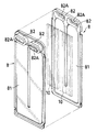
【図1】本発明の実施形態を示すカーエアコン用蒸発器の斜視図である。
【図2】蒸発器の左側面図である。
【図3】図2のIII −III 線に沿う蒸発器の断面図である。
【図4】図3の一部を拡大して示す図である。
【図5】蒸発器の中間プレートとインナーフィンとを示す分解斜視図である。
【符号の説明】
(1) …蒸発器(熱交換器)
(2) …蒸発器本体(熱交換器本体)
(3) …偏平中空部
(3A)…冷媒通路
(4) …第1ヘッダ部
(4A)…冷媒導入孔(流体導入孔)
(41)…垂直仕切壁
(41B) …冷媒通過孔(流体通過孔)
(5) …第2ヘッダ部
(5A)…冷媒排出孔(流体排出孔)
(51)…垂直仕切壁
(6) …バイパス管
(61)…フランジ
(7) …導管接続部材
(7A)…冷媒導入通路(流体導入通路)
(7B)…冷媒排出通路(流体排出通路)
(70)…弧状段部[0001]
BACKGROUND OF THE INVENTION
The present invention relates to a heat exchanger used as an evaporator for a car air conditioner, for example. In this specification, “left and right” refers to the left and right of FIG. 3, “front” refers to the bottom of FIG. 3, and “rear” refers to the top of FIG.
[0002]
[Prior art]
As an evaporator for a conventional car air conditioner, the evaporator body has a plurality of vertical flat hollow portions having a substantially U-shaped refrigerant passage as viewed from the side and arranged at predetermined intervals in the left-right direction, A first header portion extending in the left-right direction so that the front ends of the refrigerant passages in the flat hollow portion communicate with each other, having a refrigerant introduction hole at one end and closed at the other end, and after the refrigerant passages in all the flat hollow portions A second header part that extends in the left-right direction so that the ends communicate with each other, has a refrigerant discharge hole at one end and is closed at the other end, and the refrigerant flows in a meandering manner in the evaporator body, Some header sections are provided with at least one vertical partition wall, and the bypass pipe is inserted through the refrigerant introduction hole of the first header section and the coolant passage hole formed in the vertical partition wall. . The bypass pipe was temporarily fastened to the edge of the refrigerant fluid introduction hole of the first header part by caulking one end of the bypass pipe with a pipe expanding punch, and then brazed to the other components of the evaporator in the furnace. .
[0003]
[Problems to be solved by the invention]
However, if the temporarily assembled evaporator has an in-furnace attitude, for example, with the temporarily secured end of the bypass pipe facing upward, the bypass pipe will fall if the bypass pipe is insufficiently caulked. There was a risk that a problem of brazing would occur.
[0004]
An object of the present invention is to enable a bypass pipe to be securely held and fixed at a predetermined position without being affected by a caulking condition or an in-furnace attitude in a heat exchanger provided with a bypass pipe.
[0005]
[Means for Solving the Problems]
The heat exchanger according to the present invention includes a plurality of vertical flat hollow portions each having a substantially U-shaped fluid passage as viewed from the side and disposed at predetermined intervals in the left-right direction. A first header portion extending in the left-right direction so that the front ends of the fluid passages in the flat hollow portion communicate with each other, having a fluid introduction hole at one end and closed at the other end, and after the fluid passages in all the flat hollow portions A second header portion that extends in the left-right direction so that the ends communicate with each other, has a fluid discharge hole at one end, and is closed at the other end, so that the fluid flows in a meandering manner in the heat exchanger body In addition, at least one vertical partition wall is provided in each header portion, and a bypass pipe having a flange at one end is inserted across the fluid introduction hole of the first header portion and the fluid passage hole formed in the vertical partition wall. and, heat exchanger body, the side The even number of intermediate plates provided with a substantially U-shaped fluid passage forming recess and a pair of header forming recesses that are connected to the front and rear ends of the recess and deeper than the recess are formed in the header forming recesses. It is formed by brazing so that the bottom walls overlap each other, and by brazing the side plate to the intermediate plates on both the left and right ends, and through holes are formed on both front and rear sides of the upper end of one side plate, A reinforcing plate having two front and rear through holes corresponding to these through holes is brazed to the outer surface of the upper end of one side plate, the front through holes of both plates constitute a fluid introduction hole, and the rear through holes are constitutes a fluid discharge hole, the through hole peripheral portion of the front of the reinforcing plate, annular inward protrusion that protrudes in the first header portion is formed, the fluid introducing passage Oyo Conduit connection having at least a fluid introduction passage of the fluid discharge passages, and an annular step portion that can receive a flange of a bypass pipe or an arc-shaped step portion that can receive a part of the flange at the inner end portion of the fluid introduction passage The member is brazed to the reinforcing plate so that the flange of the bypass pipe is sandwiched between the stepped portion thereof and the fluid introduction hole edge portion of the first header portion.
In the heat exchanger according to the present invention, the reinforcing plate may be formed of an aluminum double-sided brazing sheet .
[0006]
DETAILED DESCRIPTION OF THE INVENTION
Next, an embodiment of the present invention will be described below with reference to FIGS.
[0007]
In this embodiment, the present invention is applied to an evaporator for a car air conditioner. In the illustrated evaporator (1), the evaporator main body (2) has a plurality of vertical flattened parts having substantially U-shaped refrigerant passages (3A) as viewed from the side and arranged at predetermined intervals in the left-right direction. It extends in the left-right direction so that the hollow portion (3) and the front ends of the refrigerant passages (3A) of all the flat hollow portions (3) communicate with each other, has a refrigerant introduction hole (4A) on the left end, and the right end is closed. The first header part (4) and the rear ends of the refrigerant passages (3A) of all the flat hollow parts (3) extend in the left-right direction and have a refrigerant discharge hole (5A) at the left end. And a second header portion (5) whose right end is closed. In addition, one vertical partition wall (41) (51) is provided in each header part (4) (5) so that the refrigerant flows in a meandering manner in the evaporator body (2), and A bypass pipe (6) having a flange (61) at the left end is inserted across the refrigerant introduction hole (4A) of the first header section (4) and the refrigerant passage hole (4B) formed in the vertical partition wall (41). ing. An arc-shaped step portion having a refrigerant introduction passage (7A) and a refrigerant discharge passage (7B) and capable of receiving a part of the flange (61) of the bypass pipe (6) at the inner end of the refrigerant introduction passage (7A) ( 70) so that the pipe connecting member (7) can sandwich the flange (61) between the step (70) and the edge of the refrigerant introduction hole (4A) of the first header (4). It is fixed to the evaporator body (2).
[0008]
The evaporator body (2) is a U-shaped refrigerant passage forming recess (81) viewed from the side and a pair of header sections that are connected to both front and rear ends of the recess (81) and deeper than the recess (81). An even number of intermediate plates (8) having recesses (82) are joined so that the bottom walls of these header-forming recesses (82) are overlapped, and side plates are attached to the intermediate plates (8) at both left and right ends. It is formed by joining plates (9).
[0009]
Each intermediate plate (8) has a horizontally oblong refrigerant passage hole (82A) formed in the bottom wall of the header portion forming recess (82) except for a part of which will be described later. A bottom wall of the first header portion forming recess (82) in the intermediate plate (8) located slightly near the right end from the center of the evaporator body (2) is smaller than the refrigerant passage hole (82A) and has a bypass pipe ( A circular coolant passage hole (82B) having a diameter slightly larger than the outer diameter of 6) is formed, and the bottom wall constitutes a vertical partition wall (41) of the first header section (4). A circular coolant passage hole (82B) is formed in the bottom wall of the first header portion forming recess (82) in the two intermediate plates (8) located approximately in the middle between the center and the left end of the evaporator body (2). A plurality of small circular coolant passage holes (82C) are formed around the hole (82B). The bottom wall of the second header forming recess (82) in the intermediate plate (8) located slightly toward the left end from the center of the evaporator body (2) has no refrigerant passage hole, and the bottom wall is 2 constitutes a vertical partition wall (51) of the header section (5).
[0010]
Inner fins (10) made of corrugated fins are disposed and fixed on the two vertical parts in the front and rear of the substantially U-shaped refrigerant passage (3A) of each flat hollow part (3) (see FIG. 5).
[0011]
A circular through hole (9A) is formed in front of the upper end of the left side plate (9), and a horizontally long circular through hole (9B) is formed in the rear side thereof. A reinforcing plate (11) having two through holes (11A) and (11B) corresponding to these through holes (9A) and (9B) is joined to the outer surface of the upper end of the left side plate (9). . An annular inward projecting portion (111) projecting into the first header portion (4) is formed at the peripheral portion of the front circular through hole in the reinforcing plate (11). The front through holes (9A) and (11A) of these plates (9) and (11) constitute the refrigerant introduction hole (4A), and the rear through holes (9B) and (11B) constitute the refrigerant discharge hole (5A). ing.
[0012]
The conduit connecting member (7) includes a plate-like member (71) and a block-like member (72). As shown in FIGS. 1 and 2, the plate-like member (71) has a substantially home base shape in which the lower part is tapered downward as viewed from the side. This plate-like member (71) has a front refrigerant passage (71A) having one end opened at the upper front corner of the inner surface of the member and the other end opened at the lower end of the outer surface of the member, and one rear end of the inner surface of the member. A rear refrigerant passage (71B) having an opening at the corner and the other end opened at the center of the outer surface of the member, and the front refrigerant passage (71A) communicates with the first header portion (4). The passage (71B) is joined to the outer surface of the reinforcing plate (11) so as to communicate with the second header portion (5). The arc-shaped step (70) is formed at the inner end of the front refrigerant passage (71A) of the plate-like member (71). As shown in FIGS. 1 and 2, the block-shaped member (72) has a substantially vertically long cross section. This block-shaped member (72) has horizontally penetrating refrigerant passages (72B) (72A) at the upper and lower portions thereof, and the upper refrigerant passage (72B) is the rear refrigerant passage (71B) of the plate-like member (71). ) And the lower refrigerant passage (72A) is fixed to the outer surface of the plate member (71) so as to communicate with the front refrigerant passage (71A) of the plate member (71). The front refrigerant passage (71A) and the lower refrigerant passage (72A) of these members (71) and (72) constitute a refrigerant discharge passage (7A), and the rear refrigerant passage (71B) and the upper refrigerant passage (72B). A refrigerant discharge passage (7B) is formed. An annular conduit insertion port (721) projecting outward is provided at the outer peripheral edge of the upper and lower refrigerant passages (72A) (72B) of the block-shaped member (72). An O-ring (12) is fitted in these conduit insertion ports (721).
[0013]
Outer fins (13) made of corrugated fins are interposed between adjacent flat hollow portions (3) and joined to the outer surfaces of the flat hollow portions (3). Left side plate (9) Both horizontal bent portions (14A) tips of the bent plate (14) having horizontal bent portions (14A) at both upper and lower ends are joined to the outer surface, and both plates (9) (14) Outer fins (13) made of corrugated fins are interposed between the plates (9) and (14). Further, the outer surface of the right side plate (9) has a horizontal bent portion (15A) at both upper and lower end portions and a vertical bent portion (15B) bent upward from the tip of the upper horizontal bent portion (15A). Both horizontal bent portions (15A) of the bent plate (15) and the inner end of the vertical bent portion (15B) are joined, and outer fins (13) made of corrugated fins are interposed between the plates (9) and (15). The two plates (9) and (15) are joined to the facing surfaces.
[0014]
Among the components of the evaporator (1), the intermediate plate (8), the side plate (9), the reinforcing plate (11), and the bent plates (14) and (15) are formed from an aluminum double-sided brazing sheet. .
[0015]
As indicated by arrows in FIG. 3, the refrigerant exchanges heat with the air flowing between the adjacent flat hollow portions (3) while flowing in a meandering manner in the evaporator body (2). Cool the air. Specifically, first, the refrigerant is introduced from the conduit (not shown) into the first header section right section (4R) through the coolant introduction passage (7A) and the bypass pipe (6) of the conduit connection member (7). . The introduced refrigerant passes through the refrigerant passage (3A) of the flat hollow portion (3) connecting the two compartments (4R) and (5R) from the compartment (4R) toward the right compartment (5R) of the second header portion. Next, the refrigerant passage (3A) of the flat hollow portion (3) connecting the two compartments (5R) (4L) from the second header portion right compartment (5R) toward the first header portion left compartment (4L) ), And the refrigerant passage in the flat hollow portion (3) communicating the two compartments (4L) and (5L) from the first header left compartment (4L) toward the second header left compartment (5L) After flowing through (3A), it is discharged through the refrigerant discharge passage (7B) of the conduit connecting member (7).
[0016]
The evaporator (1) is assembled as follows, for example. That is, first, the intermediate plate (8), the side plate (9), the reinforcing plate (11), the bent plate (14) (15), the inner fin (10), the outer fin (13), the plate-like member (71) Then, the bypass pipe (6) is temporarily assembled using a jig. At this time, the bypass pipe (6) has its flange (61) sandwiched between the arc-shaped step part (70) of the plate-like member (71) and the edge of the refrigerant introduction hole (4A) of the first header part (4). Since it is worn, it is easily positioned, and there is no misalignment even if it is not particularly caulked. Next, the temporarily assembled parts are brazed in a furnace. At this time, the displacement of the bypass pipe (6) does not occur regardless of the position in the furnace. Thereafter, the block member (72) is fixed to the plate member (71) with a set screw or the like. Thus, the assembly of the evaporator (1) is completed.
[0017]
【The invention's effect】
As described above, in the heat exchanger according to the present invention, the conduit connecting member is attached to the reinforcing plate so that the flange of the bypass pipe can be sandwiched between the annular step portion or the arc-like step portion and the fluid introduction hole edge portion of the first header portion. Since it is brazed, there is no possibility of causing a positional deviation of the bypass pipe and a manufacturing defect caused by the positional deviation in the manufacturing process. Moreover, since it is not necessary to temporarily fix the bypass pipe by caulking, the manufacturing process can be reduced accordingly.
[Brief description of the drawings]
FIG. 1 is a perspective view of an evaporator for a car air conditioner showing an embodiment of the present invention.
FIG. 2 is a left side view of the evaporator.
FIG. 3 is a cross-sectional view of the evaporator taken along line III-III in FIG.
FIG. 4 is an enlarged view showing a part of FIG. 3;
FIG. 5 is an exploded perspective view showing an intermediate plate and an inner fin of the evaporator.
[Explanation of symbols]
(1)… Evaporator (heat exchanger)
(2)… Evaporator body (heat exchanger body)
(3) ... Flat hollow part
(3A) ... Refrigerant passage
(4) ... 1st header
(4A)… Refrigerant introduction hole (fluid introduction hole)
(41)… Vertical partition wall
(41B) ... Refrigerant passage hole (fluid passage hole)
(5) ... 2nd header
(5A) ... Refrigerant discharge hole (fluid discharge hole)
(51)… Vertical partition wall
(6)… Bypass pipe
(61)… Flange
(7)… Conduit connection member
(7A)… Refrigerant introduction passage (fluid introduction passage)
(7B)… Refrigerant discharge passage (fluid discharge passage)
(70)… Arc step
Claims (2)
熱交換器本体は、側面よりみて略U形の流体通路形成用凹部および同凹部の前後両端に連なりかつ同凹部よりも深い1対のヘッダ部形成用凹部を備えた偶数枚の中間プレートをこれらのヘッダ部形成用凹部の底壁どうしを重ね合わせるようにしてろう付けするとともに、左右両端の中間プレートにサイドプレートをろう付けすることにより形成されており、
一方のサイドプレートの上端部の前後両側に貫通孔が形成され、これらの貫通孔に対応する前後2つの貫通孔を有する補強プレートが一方のサイドプレートの上端部外面にろう付けされ、これら両プレートの前側貫通孔が流体導入孔を構成し、後側貫通孔が流体排出孔を構成しており、
補強プレートにおける前側の貫通孔周縁部に、第1ヘッダ部内に突出した環状内方突出部が形成され、
流体導入通路および流体排出通路のうち少なくとも流体導入通路を有しかつ流体導入通路の内端部にバイパス管のフランジを受け得る環状段部または同フランジの一部を受け得る弧状段部が設けられている導管接続部材が、これの段部と第1ヘッダ部の流体導入孔縁部とでバイパス管のフランジを挟み着けるように補強プレートにろう付けされている、熱交換器。The heat exchanger main body has a substantially U-shaped fluid passage when viewed from the side and a plurality of vertical flat hollow portions arranged at predetermined intervals in the left-right direction, and front ends of the fluid passages of all the flat hollow portions The left and right sides extend so as to communicate with each other, the first header portion having a fluid introduction hole at one end and the other end closed, and the rear ends of the fluid passages of all the flat hollow portions communicate with each other. A second header portion extending in the direction and having a fluid discharge hole at one end and closed at the other end, and at least one in each header portion so that the fluid flows in a meandering manner in the heat exchanger body. A bypass pipe provided with a vertical partition wall and having a flange at one end is inserted across the fluid introduction hole of the first header portion and the fluid passage hole formed in the vertical partition wall,
The heat exchanger main body includes an approximately U-shaped fluid passage forming recess and an even number of intermediate plates provided with a pair of header forming recesses that are connected to both front and rear ends of the recess and deeper than the recess. And brazing so that the bottom walls of the recess for forming the header portion overlap each other, and by brazing the side plates to the intermediate plates on both the left and right ends,
Through holes are formed on both front and rear sides of the upper end of one side plate, and a reinforcing plate having two front and rear through holes corresponding to these through holes is brazed to the outer surface of the upper end of one side plate. The front through hole constitutes a fluid introduction hole, and the rear through hole constitutes a fluid discharge hole,
An annular inward protruding portion that protrudes into the first header portion is formed on the peripheral edge of the through hole on the front side of the reinforcing plate,
An annular step portion that has at least a fluid introduction passage of the fluid introduction passage and the fluid discharge passage and can receive a flange of the bypass pipe is provided at an inner end portion of the fluid introduction passage, or an arc-shaped step portion that can receive a part of the flange. A heat exchanger in which the conduit connecting member is brazed to the reinforcing plate so as to sandwich the flange of the bypass pipe between the step portion thereof and the fluid introduction hole edge of the first header portion.
Priority Applications (1)
| Application Number | Priority Date | Filing Date | Title |
|---|---|---|---|
| JP09221499A JP4124905B2 (en) | 1999-03-31 | 1999-03-31 | Heat exchanger |
Applications Claiming Priority (1)
| Application Number | Priority Date | Filing Date | Title |
|---|---|---|---|
| JP09221499A JP4124905B2 (en) | 1999-03-31 | 1999-03-31 | Heat exchanger |
Publications (3)
| Publication Number | Publication Date |
|---|---|
| JP2000283603A JP2000283603A (en) | 2000-10-13 |
| JP2000283603A5 JP2000283603A5 (en) | 2006-03-02 |
| JP4124905B2 true JP4124905B2 (en) | 2008-07-23 |
Family
ID=14048202
Family Applications (1)
| Application Number | Title | Priority Date | Filing Date |
|---|---|---|---|
| JP09221499A Expired - Fee Related JP4124905B2 (en) | 1999-03-31 | 1999-03-31 | Heat exchanger |
Country Status (1)
| Country | Link |
|---|---|
| JP (1) | JP4124905B2 (en) |
Families Citing this family (5)
| Publication number | Priority date | Publication date | Assignee | Title |
|---|---|---|---|---|
| US6321562B1 (en) * | 1999-06-29 | 2001-11-27 | Calsonic Kansei Corporation | Evaporator of automotive air-conditioner |
| CN1321310C (en) * | 2001-02-28 | 2007-06-13 | 昭和电工株式会社 | Heat exchanger |
| AU2003208623A1 (en) * | 2002-02-28 | 2003-09-09 | Showa Denko K.K. | Evaporator and refrigeration cycle |
| JP4095818B2 (en) * | 2002-03-27 | 2008-06-04 | 株式会社日本クライメイトシステムズ | Heat exchanger |
| JP6084447B2 (en) * | 2012-12-06 | 2017-02-22 | カルソニックカンセイ株式会社 | Evaporator structure |
-
1999
- 1999-03-31 JP JP09221499A patent/JP4124905B2/en not_active Expired - Fee Related
Also Published As
| Publication number | Publication date |
|---|---|
| JP2000283603A (en) | 2000-10-13 |
Similar Documents
| Publication | Publication Date | Title |
|---|---|---|
| JP3014434B2 (en) | Heat exchanger | |
| US8186719B2 (en) | Pipe connecting structure of heat exchanger | |
| JPH04353395A (en) | Heat exchanger | |
| JPH08254399A (en) | Heat exchanger | |
| US8091617B2 (en) | Heat exchanger | |
| JP3156565B2 (en) | Heat exchanger | |
| JP4190289B2 (en) | Heat exchanger | |
| JP4217469B2 (en) | Heat exchanger | |
| EP0745821B1 (en) | Method of manufacturing a heat exchanger with divided header tank | |
| JP4124905B2 (en) | Heat exchanger | |
| CA2590170C (en) | Bracket for mounting heat exchanger | |
| JPH0571892A (en) | Heat exchanger | |
| JP2000055573A (en) | Refrigerant evaporator | |
| JPH0435742Y2 (en) | ||
| JP2003004395A (en) | Heat exchanger | |
| JPH09280778A (en) | Laminated type heat exchanger | |
| JPH0587483A (en) | Aluminum heat exchanger | |
| JPH08240395A (en) | Heat exchanger | |
| JPH08271167A (en) | Heat exchanger | |
| JP2000283603A5 (en) | ||
| JPH08219680A (en) | Heat-exchanger | |
| JP3051477B2 (en) | Heat exchanger | |
| JP3297255B2 (en) | Heat exchanger | |
| JPH04278196A (en) | Heat exchanger | |
| KR100908097B1 (en) | heat transmitter |
Legal Events
| Date | Code | Title | Description |
|---|---|---|---|
| A521 | Written amendment |
Free format text: JAPANESE INTERMEDIATE CODE: A523 Effective date: 20060118 |
|
| A621 | Written request for application examination |
Free format text: JAPANESE INTERMEDIATE CODE: A621 Effective date: 20060118 |
|
| A977 | Report on retrieval |
Free format text: JAPANESE INTERMEDIATE CODE: A971007 Effective date: 20071113 |
|
| A131 | Notification of reasons for refusal |
Free format text: JAPANESE INTERMEDIATE CODE: A131 Effective date: 20071127 |
|
| A521 | Written amendment |
Free format text: JAPANESE INTERMEDIATE CODE: A523 Effective date: 20080123 |
|
| TRDD | Decision of grant or rejection written | ||
| A01 | Written decision to grant a patent or to grant a registration (utility model) |
Free format text: JAPANESE INTERMEDIATE CODE: A01 Effective date: 20080408 |
|
| A01 | Written decision to grant a patent or to grant a registration (utility model) |
Free format text: JAPANESE INTERMEDIATE CODE: A01 |
|
| A61 | First payment of annual fees (during grant procedure) |
Free format text: JAPANESE INTERMEDIATE CODE: A61 Effective date: 20080507 |
|
| R150 | Certificate of patent or registration of utility model |
Free format text: JAPANESE INTERMEDIATE CODE: R150 |
|
| FPAY | Renewal fee payment (event date is renewal date of database) |
Free format text: PAYMENT UNTIL: 20110516 Year of fee payment: 3 |
|
| LAPS | Cancellation because of no payment of annual fees |