JP4122575B2 - X-ray cine imaging device - Google Patents
X-ray cine imaging device Download PDFInfo
- Publication number
- JP4122575B2 JP4122575B2 JP17753098A JP17753098A JP4122575B2 JP 4122575 B2 JP4122575 B2 JP 4122575B2 JP 17753098 A JP17753098 A JP 17753098A JP 17753098 A JP17753098 A JP 17753098A JP 4122575 B2 JP4122575 B2 JP 4122575B2
- Authority
- JP
- Japan
- Prior art keywords
- tube
- ray
- cine
- subject
- time
- Prior art date
- Legal status (The legal status is an assumption and is not a legal conclusion. Google has not performed a legal analysis and makes no representation as to the accuracy of the status listed.)
- Expired - Lifetime
Links
Images
Landscapes
- X-Ray Techniques (AREA)
- Apparatus For Radiation Diagnosis (AREA)
Description
【0001】
【発明の属する技術分野】
この発明は、X線撮影装置に関し、とくに心臓や血管系の動きを捉えるため動画の撮影を行うX線シネ撮影装置に関する。
【0002】
【従来の技術】
従来より心臓や心臓の血管系のX線診断には、速い動きに対応するためシネカメラ装置を用いたX線シネ撮影が行われている。
【0003】
X線シネ撮影装置には、被写体の透過X線を可視光像に変換するイメージインテンシファイヤが使用されるがこのイメージインテンシファイアの線質特性及び造影剤のX線吸収特性との関係で50kV〜80kVの管電圧で撮影すると、コントラストの良い写真が得られると言われている。
【0004】
従来のX線シネ撮影装置では、撮影時間(パルス幅)はシネカメラのフィルムスピードに応じて決定され、また、X線シネ撮影のスタート条件(管電圧、管電流)は術者により設定され、これらの条件の下で撮影が開始される。撮影中、造影剤注入等により被写体が変化するので、その変化に対してシネフィルムの撮影濃度を一定に保つためX線条件の制御が行われる。まず、ホトタイマによってX線放射時間が制御され、つぎに、こうして撮影時間が変化するとその実測された撮影時間が術者により最初に設定された撮影時間(パルス幅)に近づくように、管電圧を変化させている。また、X線の定格を充分引き出すために、管電圧の変化に応じて管電流を変化させてX線管に常に一定の負荷をかける方式(アイソワット制御)が行われている。
【0005】
したがって、撮影時間が変化する過渡的な状態を除けば、人体厚さ(被写体厚さ)に対するシネ撮影時の管電圧RkV、管電流RmAおよび撮影時間Rsecの関係は図6に示すような状態に収束する。すなわち、造影剤等によって等価的に人体厚さが厚くなると、管電圧が上がり、それに応じて管電流が減少し、これらの結果として撮影時間は一定に保たれる。
【0006】
【発明が解決しようとする課題】
しかしながら、従来の方式によればフィルムの濃度は被写体の状態によらず一定に保たれるのであるが、コントラストの点で画質に問題が生じることがある。いかなる被写体厚、被検部位においても同一の制御方式が行われているため、被写体のX線吸収が少ない場合、たとえば被写体厚が小さい部位によっては、ホトタイマによって、X線放射時間が設定しておいた時間より短くなり、このため管電圧が低下するとともに管電流が増加していく(アイソワット制御)。この結果、管電圧が大幅に低下してしまい、フィルムの画質はコントラストのつきすぎた診断に使えない状態になってしまう。逆に、被写体厚が少し厚くなると、定格の大きいX線管を用いた場合で定格に余裕があるにもかかわらず、管電圧が上昇しコントラストのつかない画像になってしまう。
【0007】
また、撮影中、造影剤注入等による被写体の変化に対して管電圧を変化させるため、線質が変化した画像となり、極端な場合には診断に支障が生じるという問題もある。
【0008】
この発明は、上記に鑑み、フィルム濃度を一定に保ちつつ、線質一定で良好なコントラストのシネ撮影フィルムが得られるように改善した、X線シネ撮影装置を提供することを目的とする。
【0009】
【課題を解決するための手段】
上記の目的を達成するため、この発明によるX線シネ撮影装置においては、X線管と、このX線管に対して管電圧およびフィラメント加熱電流を加える、管電圧および管電流の調整可能な高電圧発生器と、被写体の透過X線を可視光像に変換する像変換器と、該可視光像を撮影するTVカメラおよびシネカメラと、上記の可視光像をTVカメラとシネカメラとに切り換えて導く光学系と、上記TVカメラの出力ビデオ信号が送られて透視像を表示する画像モニター装置と、上記光学系に挿入され、上記可視光像の輝度を検出し、電気信号に変換する光電変換器と、透視時にビデオ信号の輝度に応じて上記高電圧発生器を制御してX線管に印加する管電圧を変えることにより表示画像の輝度を一定にする透視制御装置と、あらかじめ透視時において求められた、被写体厚ごとに画像輝度が収束したときの管電圧をその被写体厚との関係で記憶する第1の記憶装置と、シネ撮影時において最適なものとしてあらかじめ求められた管電圧、管電流および撮影時間のデータを被写体厚に関して記憶するとともに、管電圧を制御する制御方式、管電流を制御する制御方式および撮影時間を制御する制御方式のいずれが最適であるかを被写体厚の範囲に関して記憶する第2の記憶装置と、シネ撮影時にシネカメラからのシャッターパルス信号に応じてX線開始信号を生じて高電圧発生器からX線管への管電圧印加を開始させるパルス発生器と、シネ撮影時に上記の光電変換器の出力を積分しその積分値が設定値に達したときにX線遮断信号を生じて上記の高電圧発生器からX線管への管電圧印加を停止させるホトタイマと、実際の被写体に対するシネ撮影に先立ってその被写体の透視を行ったときに上記の透視制御装置により収束した管電圧に基づき上記の第1の記憶装置から被写体厚を推定し、この推定被写体厚に対応する管電圧、管電流および撮影時間のデータおよび制御方式を第2の記憶装置から求めてシネ撮影のスタート時の管電圧、管電流および撮影時間および制御方式を設定するとともに、シネ撮影中の被写体の変化により上記X線開始信号からX線遮断信号までの時間が変化したときに、その時間と上記の設定された撮影時間との差に応じて、設定された制御方式に基づいた管電圧および管電流の制御を行い、かつ管電圧、管電流および上記の差を監視して制御方式の変更をも行うシネ撮影制御装置とが備えられることが特徴となっている。
【0010】
実際の被写体に対するシネ撮影に先立ってその被写体について透視を行うと、透視制御装置の作用によって表示画像の輝度が一定のものとなるように管電圧が制御されて収束する。この管電圧に基づき、収束時の管電圧と被写体厚との関係を記憶している第1の記憶装置から、その被写体厚を推定することができる。そして、第2の記憶装置には、シネ撮影時において最適な管電圧、管電流および撮影時間のデータが被写体厚に関して記憶され、かつ、管電圧を制御する制御方式、管電流を制御する制御方式および撮影時間を制御する制御方式のいずれが最適であるかが被写体厚の範囲に関して記憶されているので、上記の推定被写体厚に基づきこの第2の記憶装置から、シネ撮影のスタート時の管電圧、管電流および撮影時間および制御方式を設定することができる。つまり、シネ撮影のスタート時には、その実際の被写体の厚さに最適なX線条件および制御方式が定められるので、収束時間を短縮することができる。そのため、被写体が赤ん坊など薄いときでも、撮影スタート以前にその被写体厚に最適なスタート条件および制御方式が選択でき適性画質で撮影が始められる。
【0011】
そして、シネ撮影中に造影剤注入などによって被写体が変化したとき、ホトタイマの作用によってX線遮断信号が生じるまでの時間が変わり、X線開始信号からX線遮断信号までの時間と設定されたとの差に応じて、設定された制御方式に基づいた管電圧、管電流および撮影時間の制御が行われる。このように被写体厚に応じた制御方式でX線条件が制御されることにより管電圧の変動幅が押さえられて、線質の安定したコントラストの良質な画像のシネ撮影フィルムが得られる。
【0012】
【発明の実施の形態】
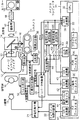
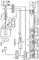
つぎに、この発明の実施の形態について図面を参照しながら詳細に説明する。図1、図2はこの発明の実施の形態を示すブロック図である。図1には主にシネ撮影時の制御系統が示され、図2には透視時に透視条件から被写体厚を求めるときの制御系統が示されている。図1、図2において、被写体10に対してX線管11からX線が放射され、被写体10を透過したX線がイメージインテンシファイア12に入射する。イメージインテンシファイア12は、入射蛍光面に入射したX線による像を、可視光像に変換し出力蛍光面に表示する。このイメージインテンシファイア12の出力蛍光面に表示された可視光像は、一次レンズ13を経て光学系14に導かれ、その光学切換器により二次レンズ15と二次レンズ16とに切り換えられる。
【0013】
シネ撮影時には、図1の矢印で示すように、二次レンズ16を通してシネカメラ51のフィルム上に結像し、透視時には図2の矢印で示すように二次レンズ15を通してテレビカメラの撮像管17の撮像面に結像する。撮像管17の撮像面に結像した可視光像は、カメラコントロールユニット(CCU)18により読み出されてビデオ信号に変換され画像モニター装置19に伝えられ、透視像が表示される。CCU18は、また、輝度比例信号を作成し、これを透視制御装置24へ出力する(図2)。
【0014】
X線管11には高電圧発生器21から高電圧の管電圧が供給されるとともに、フィラメント加熱電流が供給される。この高電圧はインバータ制御器23によって制御され、フィラメント加熱電流はフィラメント加熱制御器22によって制御される。
【0015】
まず、被写体10の厚さと透視条件の関係を決定するために、被写体10としてファントムを用いて透視を行う。このとき、図2に示すように、術者が透視操作を行うとX線放射信号がインバータ制御器23に入力される。その結果、透視制御装置24から出力されているスタート透視条件(透視管電圧、透視管電流)に応じた周波数でインバータの発振が始まり、その出力が高電圧発生器21に送られて高電圧が発生する。この高電圧はX線管11に管電圧として印加されてX線が発生する。このときイメージインテンシファイア12から出力される可視光像は、二次レンズ15側へと切り換えられている光学系14の光学切換器により撮像管17に入力されており、CCU18からビデオ信号が生じ、これが画像モニター装置19に送られるとともに、CCU18からの輝度比例信号が透視制御装置24に送られる。
【0016】
透視制御装置24は、カメラコントロールユニット18から入力された輝度比例信号に応じて、画像モニター装置19に表示された透視像が最適輝度となるような透視条件(透視管電圧FkV、透視管電流FmA)を求めてその信号をインバータ制御器23に送る。この透視管電圧FkVを表す信号は、マイクロコンピュータ31のA/D変換器38にも入力され、その透視管電圧FkVが読み取られ図示しない透視管電圧表示器に表示される。
【0017】
マイクロコンピュータ31は、CPU32と、そのバスライン33に接続された、F−Tデータメモリ34と、T−R条件データメモリ35と、FVRデータメモリ36と、プログラムメモリ37と、上記のA/D変換器38と、出力回路39と、D/A変換器41〜43と、設定パルス幅タイマ44とを備えて構成されている。プログラムメモリ37に格納されたプログラムがバスライン33を経てCPU32に読み込まれ、CPU32がこの読み込まれたプログラムにしたがって動作することにより、マイクロコンピュータ31としての動作が行われる。
【0018】
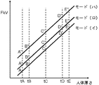
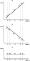
実際に据え付けられた病院で撮影する装置において、人体等価ファントムを利用した透視が行われる。ある厚さのファントムを透視するとき、上記の透視輝度自動制御ループの動作によって最適透視管電圧が得られる。すなわち、画像モニター装置19に表示された画像の輝度が最適に収束した時点で、そのときの透視管電圧FkVがCPU32の制御の下でA/D変換器38を経てF−Tデータメモリ34に書き込まれる。同時に、このときのファントム厚さも、図示しない設定器が手動で操作されることにより、あるいは自動的に、このF−Tデータメモリ34に書き込まれる。さらに他の4種のファントム厚さで透視条件を実測する。この一連の操作により、図3に示すデータがF−Tデータメモリ34に記憶される。
【0019】
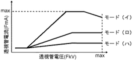
これによりF−Tデータメモリ34には、図3に示すような、各透視モードにおける、被写体厚さ(人体厚さ)と透視管電圧FkVとの関係が記憶させられることになる。図3のA〜E、A’〜E’、A”〜E”は5つの厚さのそれぞれにおける、各透視モードごとの最適透視管電圧である。各透視モードにおける透視管電圧FkVと透視管電流FmAとの関係は、図4の特性図に示す通りである。
【0020】
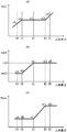
つぎに、同じく人体等価ファントムを用いて、被写体厚さとシネ撮影の撮影スタート条件との関係を求め、T−R条件データメモリ35に書き込む。このとき、上記の透視条件を求めたときのファントム厚さのファントムを被写体10として配置し、各々の厚さにおいて所望のシネ写真が得られるよう、図示しない撮影条件設定器により撮影条件を設定してシネ撮影を行ってみる。これにより、5つの人体厚さtA,tB,tC,tD,tEにおける最適撮影スタート条件、撮影管電圧RkV、撮影管電流RmA、撮影時間Rsecが、たとえば図5の(a)、(b)、(c)のように求められ、このデータがT−R条件データメモリ35に書き込まれる。
【0021】
この図5の(a)は被写体厚さと開始時の撮影管電圧の関係を、同図(b)は被写体厚さと開始時の管電流の関係を、同図(c)は被写体厚さと開始時の撮影時間(パルス幅)の関係を示す特性図である。図中vA〜vE点、aA〜aE点、sA〜sE点は図3のA〜E点の厚さに対応する各条件、つまり撮影管電圧、撮影管電流、撮影時間である。
【0022】
これら図5の(a)、(b)、(c)は、シネ撮影中の被写体10の変化に対して、被写体厚tA〜tBの間は管電流・撮影時間を一定とし管電圧のみ変化させて管電圧の低下を押さえ、tB〜tCの間は管電圧・撮影時間を一定とし管電流のみ変化させて管電圧を一定に保ち、tC〜tDの間は管電圧・管電流(大)を一定とし撮影時間のみ変化させて管電圧を一定に保ち、さらに厚い被写体厚tD〜tEの間は被写体の変化に対して管電流(大)・撮影時間(長)を一定とし再度管電圧を変えて対応することも示している。
【0023】
この被写体厚さtA〜tBの間での管電圧のみ変化させる自動制御方式の選択、被写体厚さtB〜tCの間での管電流のみ変化させる自動制御方式の選択、被写体厚さtC〜tDの間での撮影時間のみ変化させる自動制御方式の選択、さらに厚い被写体厚さtD〜tEの間での再度管電圧のみ変化させる自動制御方式の選択という、自動制御方式の被写体厚さに応じた選択も、併せてT−R条件データメモリ35に記憶される。
【0024】
このようなF−Tデータメモリ34およびT−R条件データメモリ35への書き込みを行った後、実際の被写体10に対するシネ撮影を行う。このシネ撮影時には、まず最初に、位置決めのための透視を行う。被写体10をイメージインテンシファイア12の前面に位置させ、光学系14の光学切換器を撮像管17側に切り換えた状態で、図示しない透視スイッチをオンにして、上記の透視時と同様にインバータ制御器23にX線放射信号を入力させて高電圧発生器21からX線管11に高電圧を印加せしめ、被写体10にX線を照射して、シネ撮影前の位置決めのための透視を行う。この際、CCU18からの輝度比例信号に応じて透視制御装置24が、画像モニタ装置19に表示された画像が所定の輝度になるように透視条件(透視管電圧FkV)を制御する。こうして、被写体10の厚さに対応した透視管電圧FkVが自動的に定められて輝度が安定する。
【0025】
この自動的に設定された透視管電圧FkVが、マイクロコンピュータ31のA/D変換器38により読み取られ、そのFkVによりF−Tデータメモリ34がアクセスされる。F−Tデータメモリ34には、上記の通り透視時の被写体厚さと管電圧との関係に関するデータが記憶されており、この関係から実際の被写体10の厚さが推定されることになる。実際の被写体10の厚さが推定されると、CPU32が、この推定厚さをT−R条件データメモリ35に保管されたデータと突き合わせ、被写体10の推定厚さに対応した、シネ撮影時の最適の撮影スタート条件(管電圧・管電流・撮影時間)を求める。
【0026】
この位置決めのための透視が終わった後、シネ撮影が開始される。このシネ撮影時には、図1に示すように、管電圧自動設定回路64および管電流自動設定回路65からシネ撮影のための管電圧RkVおよび管電流RmAを表す信号がインバータ制御器23に送られるとともに、マイクロコンピュータ31のA/D変換器38にも送られる。管電圧自動設定回路64および管電流自動設定回路65には、シネ撮影スタート時点では、上記のT−R条件データメモリ35から得た管電圧初期値および管電流初期値がD/A変換器42、43を介して送られてきており、高電圧発生器21からX線管11に与えられる管電圧RkV、管電流RmAはその初期値となっている。また、上記のT−R条件データメモリ35から得た撮影時間が設定パルス幅タイマ44に設定される。
【0027】
このシネ撮影時、シネカメラ51からシャッターパルス信号が発生し、これがパルス発生器52に入力される。このパルス発生器52は、入力されたシャッターパルス信号に応じてX線開始信号を発生し、これをX線放射回路53に送るとともに、設定パルス幅タイマ44に送る。
【0028】
X線放射回路53は、X線放射信号をインバータ制御器23に与える。X線放射回路53は、X線開始信号が入力された時点でX線放射信号を立ち上げ、X線遮断信号が入力された時点でそのX線放射信号を立ち下げる。X線遮断信号は、イメージインテンシファイア12の出力像の明るさの積分値が所定値に到達したとき、シネカメラ51のフィルムの露光濃度が設定値に達したとして、生じるものである。
【0029】
このX線遮断信号はホトタイマによって作成される。すなわち、光学系14に挿入された光電子増倍管(PMT)54と、積分器55と、濃度設定器56と、比較器57とによってホトタイマを構成する。光電子増倍管54にイメージインテンシファイア12の出力光の一部を導き、その光電流出力を光電流積分器55で積分する。濃度設定器56には、フィルム濃度の設定値があらかじめ設定されており、この濃度設定器56から出力される設定値と光電流積分器55からの積分値とが濃度比較器57で比較され、積分値が設定値を上回ったときに濃度比較器57からX線遮断信号が生じてX線放射回路53に送られる。このX線遮断信号に応じてX線放射信号が立ち下がり、インバータ制御器23を通じて高電圧の発生が停止させられることにより、X線管11からのX線が遮断され、その結果、シネフィルムへの露光濃度が濃度設定器で設定した値に保たれることになる。
【0030】
一方、パルス発生器52からのX線開始信号が設定パルス幅タイマ44に送られると、その入力時点からタイマ動作が開始される。この設定パルス幅タイマ44は、X線開始信号の入力時点で立ち上がり、撮影時間として設定された時間が経過したときに立ち下がる信号を出力し、この信号を比較器58に送っている。比較器58には、実際のX線放射時間を表すX線放射信号が送られてきており、2つの入力信号のパルス幅の差に応じた出力を生じる。すなわち、この差信号は、実際のX線放射時間と設定放射時間との差を表す。
【0031】
この比較器58からの差信号は、スイッチ61、62、63を経てそれぞれ管電圧自動設定回路64、管電流自動設定回路65、およびA/D変換器38に送られる。これらのスイッチ61〜63は、T−R条件データメモリ35のデータに基づきCPU32によって制御されている出力回路39からの出力によって制御される。被写体厚がtA〜tBの間の場合はシネ撮影中の被写体10の変化に対して管電圧を変化させる選択信号が出力回路39から出力されスイッチ61がオンする。同様にtB〜tCの間は被写体10の変化に対して管電流を変化させる選択信号が出力回路39から出力されスイッチ62がオンする。tC〜tDの間は被写体10の変化に対して撮影時間を変化させる選択信号が出力回路39から出力されスイッチ63がオンする。さらに厚い被写体厚tD〜tEの間は被写体10の変化に対して再度管電圧を変化させる選択信号が出力回路39から出力されスイッチ61がオンする。
【0032】
ここでは被写体厚がtB〜tCの間にありスイッチ62がオンした場合を例にあげてシネ撮影中の動作について説明する。このとき、比較器58からの差信号はスイッチ62を経て管電流自動設定回路65に送られる。そこで、管電流自動設定回路65は、その入力された差信号に応じて、つまり、実測X線放射パルス幅と設定パルス幅との誤差に応じて、管電流を上昇あるいは下降させる管電流信号を出力する。スタート時の撮影条件は透視時の条件より決定された最適条件であるためこの時の差信号はゼロとなっている。そのため、この条件を維持したままシネ撮影が継続されていく。
【0033】
造影剤が注入され被写体10の状態が厚さが増加する方向へ変化すると実測X線放射パルス幅が設定パルス幅タイマ44からのパルス幅より長くなり比較器58からの差信号が+側になり、管電流自動設定回路65からの管電流信号が上昇する。この管電流信号は、インバータ制御器23とともにマイクロコンピュータ31のA/D変換器38に入力される。マイクロコンピュータ31では入力された管電流信号値と管電圧値からフィラメント加熱値を計算し、D/A変換器41からフィラメント加熱信号を出力させ、フィラメント加熱制御器22に入力させる。フィラメント加熱制御器22による高電圧発生器21の制御によって、このD/A変換器41からの出力値でX線管11のフィラメントが加熱され、管電流が上昇する。
【0034】
こうして管電流が上昇しX線強度が上昇し、その状態で次のコマの撮影が行われる。前述のように濃度設定値に達するとX線が遮断されフィルム濃度が適性値に保たれる。そしてまた実測X線放射パルス幅と設定パルス幅タイマ44からのパルス幅が比較され、比較器58からの差信号がゼロとなるまで上記のような管電流上昇を繰り返していく。管電流が増え光電子増倍管54の出力の積分値が設定値に到達する時間が早くなり、比較器58からの差信号がゼロとなれば、この管電流が維持されたままシネ撮影が継続されていく。
【0035】
マイクロコンピュータ31ではA/D変換器38に入力された管電流信号の値を監視しており、管電流が図5(b)においてmA1を超える場合には、管電流をそれ以上に増加させることはせずに一定の値mA1とし、撮影時間を延ばすことによりフィルム濃度が上昇するような自動制御方式に切り換える。すなわち、管電流がmA1を超える場合は、被写体厚さがtCを超えるようになった場合であるから、このことがCPU32によって判断され、被写体10の変化に対して撮影時間を変化させる自動制御方式が選択されて、出力回路39からの出力によってスイッチ61、62をオフに、スイッチ63をオンにする。そこで、図5の(a)、(b)、(c)の厚さtC〜tDの間でのように、管電圧、管電流は一定のまま、撮影時間Rsecのみが変化させられることになる。
【0036】
さらにこのとき、比較器58からの差信号はオンになったスイッチ63を経てA/D変換器38に入力されて監視されている。そこで、CPU32が、撮影時間Rsecが図5の(c)のsDに到達したと判断でき、そのとき、厚さtD〜tEでの管電圧のみを変化させる自動制御方式が選択され、出力回路39からの出力によってスイッチ61がオンに、スイッチ62、63がオフにされる。そこでこのときは、比較器58からの差信号に応じて管電圧自動設定回路64が管電圧を上昇または下降させる制御を行う。
【0037】
また、上記の管電流の制御のみでシネ撮影を継続していったときに、管電流が小さくなって図5の(b)のmA2を下回るようになったときは、同様に、厚さtA〜tBでの管電圧のみを変化させる自動制御方式が選択され、出力回路39からの出力によってスイッチ61がオンに、スイッチ62、63がオフにされ、比較器58からの差信号に応じた管電圧自動設定回路64による管電圧の上昇または下降制御が行われる。
【0038】
このようにして被写体10の状態の変化に対して、管電圧、管電流および撮影時間を自動的に制御するとともに、その制御方式を選択しながら、一連のシネ撮影を終了する。したがって、X線管の定格にもよるが通常の被写体厚の大部分つまり図5のtB〜tDの間の厚さにおいて管電圧を一定にでき、線質の安定した、コントラストの良質な画像のシネ撮影フィルムを得ることができる。
【0039】
なお、シネフィルムを使用したシネ撮影のみならず、XTVカメラおよびデジタル・ラデオグラフィー装置と組み合わせてデジタル・シネ撮影するシネカメラを用いた場合も、同様に画質が向上した自動制御が行える。さらに、シネ撮影と同様にパルス状にX線を放射するパルス透視診断においてもこの制御方式を用いれば、Cアームを回転させて被写体の正面から斜位に移動した時でも管電圧が一定となり線質の変わらない見易い透視像が得られる。
【0040】
【発明の効果】
以上説明したように、この発明のX線シネ撮影装置によれば、シネ撮影スタート時点で実際の被写体の推定厚さに対応した最適X線条件と最適制御方式が定められるので、シネ撮影を最初から最適なX線条件で開始することができる。また、造影剤注入などにより被写体が変化してもその変化した被写体厚に最適な制御方式に変更してX線条件を制御するため、管電圧の変動幅を抑えて、線質の安定した、コントラストの良質な画像のシネ撮影フィルムを得ることができる。
【図面の簡単な説明】
【図1】この発明の実施の形態における主にシネ撮影時の制御系統を示すブロック図。
【図2】同実施形態における主に透視時の制御系統を示すブロック図。
【図3】透視画像輝度自動調整下での被写体厚さと透視管電圧との関係を示すグラフ。
【図4】各透視モードにおける透視管電圧と透視管電流との関係を示すグラフ。
【図5】同実施形態における、シネ撮影時の、被写体厚さに関する、管電圧、管電流および撮影時間の各特性を表すグラフ。
【図6】従来の、シネ撮影時の、被写体厚さに関する、管電圧、管電流および撮影時間の各特性を表すグラフ。
【符号の説明】
10 被写体
11 X線管
12 イメージインテンシファイア
13 一次レンズ
14 光学系
15、16 二次レンズ
17 TVカメラの撮像管
18 カメラコントロールユニット
19 画像モニター装置
21 高電圧発生器
22 フィラメント加熱制御器
23 インバータ制御器
24 透視制御装置
31 マイクロコンピュータ
32 CPU
33 バスライン
34 F−Tデータメモリ
35 T−R条件データメモリ
36 FVRデータメモリ
37 プログラムメモリ
38 A/D変換器
39 出力回路
41〜43 D/A変換器
44 設定パルス幅タイマ
51 シネカメラ
52 パルス発生器
53 X線放射回路
54 光電子増倍管
55 積分器
56 濃度設定器
57 濃度比較器
58 パルス幅比較器
61〜63 スイッチ
64 管電圧自動設定回路
65 管電流自動設定回路[0001]
BACKGROUND OF THE INVENTION
The present invention relates to an X-ray imaging apparatus, and more particularly to an X-ray cine imaging apparatus that captures a moving image to capture the movement of the heart and vascular system.
[0002]
[Prior art]
Conventionally, X-ray cine imaging using a cine camera device has been performed for X-ray diagnosis of the heart and the vascular system of the heart in order to cope with fast movement.
[0003]
An X-ray cine imaging apparatus uses an image intensifier that converts transmitted X-rays of a subject into a visible light image. The relationship between the image quality of the image intensifier and the X-ray absorption characteristic of the contrast agent is used. It is said that a photo with good contrast can be obtained by shooting at a tube voltage of 50 kV to 80 kV.
[0004]
In the conventional X-ray cine imaging apparatus, the imaging time (pulse width) is determined according to the film speed of the cine camera, and the start conditions (tube voltage, tube current) of X-ray cine imaging are set by the operator. Shooting is started under the above conditions. During imaging, the subject changes due to injection of a contrast medium or the like, so that the X-ray conditions are controlled in order to keep the imaging density of the cine film constant with respect to the change. First, the X-ray emission time is controlled by the phototimer. Next, when the imaging time changes in this way, the tube voltage is set so that the measured imaging time approaches the imaging time (pulse width) initially set by the operator. It is changing. Further, in order to sufficiently draw out the rating of X-rays, a system (isowatt control) in which a constant load is always applied to the X-ray tube by changing the tube current according to a change in the tube voltage is performed.
[0005]
Therefore, except for the transitional state where the photographing time changes, the relationship between the tube voltage RkV, the tube current RmA, and the photographing time Rsec at the time of cine photographing with respect to the human body thickness (subject thickness) is as shown in FIG. Converge. That is, when the human body thickness is equivalently increased by a contrast agent or the like, the tube voltage increases and the tube current decreases accordingly, and as a result, the imaging time is kept constant.
[0006]
[Problems to be solved by the invention]
However, according to the conventional method, the density of the film is kept constant regardless of the state of the subject, but there may be a problem in image quality in terms of contrast. Since the same control method is used for any subject thickness and region to be examined, if the subject has little X-ray absorption, for example, depending on the region where the subject thickness is small, the X-ray emission time is set by a photo timer. Therefore, the tube voltage decreases and the tube current increases (isowatt control). As a result, the tube voltage is greatly reduced, and the image quality of the film is not usable for diagnosis with too much contrast. On the other hand, if the subject thickness is a little thicker, the tube voltage will rise and an image with no contrast will be obtained even if the rated X-ray tube is used and there is a margin in the rating.
[0007]
Moreover, since the tube voltage is changed with respect to the change of the subject due to contrast medium injection during imaging, the image is changed in quality, and there is a problem that the diagnosis is hindered in an extreme case.
[0008]
SUMMARY OF THE INVENTION In view of the above, an object of the present invention is to provide an X-ray cine imaging apparatus which is improved so as to obtain a cine imaging film having a constant line quality and a good contrast while keeping the film density constant.
[0009]
[Means for Solving the Problems]
In order to achieve the above object, in an X-ray cine imaging apparatus according to the present invention, an X-ray tube, and a tube voltage and a filament heating current are applied to the X-ray tube. A voltage generator, an image converter for converting transmitted X-rays of a subject into a visible light image, a TV camera and a cine camera for capturing the visible light image, and switching the visible light image to a TV camera and a cine camera. An optical system, an image monitor device that displays an output video signal of the TV camera and displays a fluoroscopic image, and a photoelectric converter that is inserted into the optical system and detects the luminance of the visible light image and converts it into an electrical signal A fluoroscopic control device for controlling the high voltage generator according to the luminance of the video signal at the time of fluoroscopy and changing the tube voltage applied to the X-ray tube to make the luminance of the display image constant. A first storage device for storing the tube voltage when the image brightness converges for each subject thickness in relation to the subject thickness, and a tube voltage determined in advance as an optimum for cine imaging, Stores tube current and shooting time data with respect to the subject thickness, and the range of subject thickness indicates which is most appropriate: a control method that controls tube voltage, a control method that controls tube current, or a control method that controls shooting time A second storage device that stores information about a pulse generator that generates an X-ray start signal in response to a shutter pulse signal from a cine camera during cine imaging and starts tube voltage application from the high voltage generator to the X-ray tube; The output of the photoelectric converter is integrated during cine imaging, and when the integrated value reaches a set value, an X-ray cutoff signal is generated and the tube voltage is applied from the high voltage generator to the X-ray tube. A photo timer to be stopped, and the subject thickness is estimated from the first storage device based on the tube voltage converged by the fluoroscopic control device when the subject is fluoroscopically taken before the cine photographing of the actual subject. The tube voltage, tube current, and shooting time data corresponding to the estimated subject thickness and the control method are obtained from the second storage device, and the tube voltage, tube current, shooting time, and control method at the start of cine shooting are set. When the time from the X-ray start signal to the X-ray cutoff signal changes due to a change in the subject during cine imaging, the control method is set according to the difference between the time and the set imaging time. A cine imaging control device that controls the tube voltage and the tube current based on the above, and monitors the tube voltage, the tube current, and the above differences, and also changes the control method. It is a feature.
[0010]
When fluoroscopy is performed on the subject prior to the cine photographing of the actual subject, the tube voltage is controlled and converged so that the luminance of the display image becomes constant by the action of the perspective control device. Based on this tube voltage, the subject thickness can be estimated from the first storage device that stores the relationship between the tube voltage at the time of convergence and the subject thickness. In the second storage device, the optimum tube voltage, tube current, and photographing time data at the time of cine photographing are stored with respect to the subject thickness, and the control method for controlling the tube voltage, the control method for controlling the tube current Which of the control methods for controlling the photographing time is optimal is stored with respect to the range of the subject thickness, so that the tube voltage at the start of cine photographing is stored from the second storage device based on the estimated subject thickness. , Tube current and shooting time and control method can be set. That is, at the start of cine imaging, the optimum X-ray condition and control method are determined for the actual subject thickness, so that the convergence time can be shortened. Therefore, even when the subject is thin, such as a baby, the optimum start condition and control method for the subject thickness can be selected before the start of photographing, and photographing can be started with suitable image quality.
[0011]
And when the subject changes due to contrast medium injection during cine imaging, the time until the X-ray cutoff signal is generated is changed by the action of the photo timer, and the time from the X-ray start signal to the X-ray cutoff signal is set. In accordance with the difference, tube voltage, tube current, and imaging time are controlled based on the set control method. In this way, the X-ray condition is controlled by the control method according to the subject thickness, so that the fluctuation range of the tube voltage is suppressed, and a cine photographing film having a high quality image with stable contrast and good quality can be obtained.
[0012]
DETAILED DESCRIPTION OF THE INVENTION
Next, embodiments of the present invention will be described in detail with reference to the drawings. 1 and 2 are block diagrams showing an embodiment of the present invention. FIG. 1 mainly shows a control system at the time of cine imaging, and FIG. 2 shows a control system at the time of obtaining the subject thickness from the fluoroscopic conditions at the time of fluoroscopy. 1 and 2, X-rays are radiated from the
[0013]
At the time of cine photographing, an image is formed on the film of the
[0014]
The
[0015]
First, in order to determine the relationship between the thickness of the subject 10 and the fluoroscopic condition, fluoroscopy is performed using the phantom as the subject 10. At this time, as shown in FIG. 2, when the operator performs a fluoroscopic operation, an X-ray radiation signal is input to the
[0016]
The
[0017]
The microcomputer 31 includes a
[0018]
In an apparatus for photographing in an actually installed hospital, fluoroscopy using a human body equivalent phantom is performed. When a phantom with a certain thickness is seen through, the optimum fluoroscopic tube voltage is obtained by the operation of the above-described fluoroscopic brightness automatic control loop. That is, when the luminance of the image displayed on the
[0019]
As a result, the
[0020]
Next, using the same human body equivalent phantom, the relationship between the subject thickness and the shooting start condition for cine shooting is obtained and written into the TR
[0021]
5A shows the relationship between the subject thickness and the starting tube voltage, FIG. 5B shows the relationship between the subject thickness and the starting tube current, and FIG. 5C shows the subject thickness and the starting tube current. It is a characteristic view which shows the relationship of imaging | photography time (pulse width). In the figure, points vA to vE, points aA to aE, and points sA to sE are conditions corresponding to the thicknesses of points A to E in FIG. 3, that is, the tube voltage, tube current, and shooting time.
[0022]
5 (a), 5 (b), and 5 (c), with respect to the change of the subject 10 during cine photographing, the tube current and photographing time are kept constant between the subject thicknesses tA and tB, and only the tube voltage is changed. In order to suppress the drop in tube voltage, the tube voltage / shooting time is kept constant between tB and tC, and only the tube current is changed to keep the tube voltage constant. The tube voltage / tube current (large) is kept between tC and tD. The tube voltage is kept constant by changing only the shooting time, and the tube current (large) and the shooting time (long) are kept constant with respect to the change of the subject between thicker subject thicknesses tD to tE, and the tube voltage is changed again. It also shows that it corresponds.
[0023]
Selection of an automatic control method that changes only the tube voltage between the subject thicknesses tA to tB, selection of an automatic control method that changes only the tube current between the subject thicknesses tB to tC, and the subject thicknesses tC to tD Selection according to the subject thickness of the automatic control method, such as selection of an automatic control method that changes only the shooting time between, and selection of an automatic control method that changes only the tube voltage again between thicker subject thicknesses tD to tE Are also stored in the TR
[0024]
After such writing to the
[0025]
The automatically set fluoroscopic tube voltage FkV is read by the A /
[0026]
After the fluoroscopy for positioning is completed, cine imaging is started. At the time of this cine photographing, as shown in FIG. 1, signals representing the tube voltage RkV and the tube current RmA for cine photographing are sent from the tube voltage automatic setting circuit 64 and the tube current automatic setting circuit 65 to the
[0027]
During this cine imaging, a shutter pulse signal is generated from the
[0028]
The X-ray emission circuit 53 gives an X-ray emission signal to the
[0029]
This X-ray cutoff signal is generated by a photo timer. That is, the photomultiplier tube (PMT) 54 inserted in the
[0030]
On the other hand, when the X-ray start signal from the
[0031]
The difference signal from the
[0032]
Here, the operation during cine photographing will be described by taking as an example a case where the subject thickness is between tB and tC and the switch 62 is turned on. At this time, the difference signal from the
[0033]
When the contrast medium is injected and the state of the subject 10 changes in the direction in which the thickness increases, the actually measured X-ray radiation pulse width becomes longer than the pulse width from the set
[0034]
In this way, the tube current increases and the X-ray intensity increases, and the next frame is imaged in this state. As described above, when the density setting value is reached, X-rays are blocked and the film density is maintained at an appropriate value. Then, the measured X-ray radiation pulse width is compared with the pulse width from the set
[0035]
The microcomputer 31 monitors the value of the tube current signal input to the A /
[0036]
Further, at this time, the difference signal from the
[0037]
Similarly, when the cine imaging is continued only by controlling the tube current as described above, if the tube current becomes smaller than the mA2 in FIG. An automatic control system that changes only the tube voltage at tB is selected, the
[0038]
In this way, the tube voltage, the tube current, and the imaging time are automatically controlled with respect to the change in the state of the subject 10, and a series of cine imaging is completed while selecting the control method. Therefore, although it depends on the rating of the X-ray tube, the tube voltage can be made constant in a large part of the normal subject thickness, that is, the thickness between tB and tD in FIG. A cine film can be obtained.
[0039]
Note that not only cine shooting using a cine film but also a cine camera that performs digital cine shooting in combination with an XTV camera and a digital radiography apparatus can similarly perform automatic control with improved image quality. Further, in the case of pulse fluoroscopy diagnosis in which X-rays are emitted in the form of pulses as in cine imaging, if this control method is used, the tube voltage remains constant even when the C-arm is rotated and moved obliquely from the front of the subject. An easy-to-see fluoroscopic image with the same quality can be obtained.
[0040]
【The invention's effect】
As described above, according to the X-ray cine imaging apparatus of the present invention, the optimum X-ray condition and the optimal control method corresponding to the estimated thickness of the actual subject are determined at the time of starting cine imaging. To start with optimal X-ray conditions. In addition, even if the subject changes due to contrast medium injection, etc., the X-ray condition is controlled by changing to the optimal control method for the changed subject thickness. It is possible to obtain a cine film having a good contrast image.
[Brief description of the drawings]
FIG. 1 is a block diagram showing a control system mainly for cine imaging in an embodiment of the present invention.
FIG. 2 is a block diagram showing a control system mainly during fluoroscopy in the embodiment.
FIG. 3 is a graph showing the relationship between subject thickness and fluoroscopic tube voltage under fluoroscopic image brightness automatic adjustment.
FIG. 4 is a graph showing the relationship between fluoroscopic tube voltage and fluoroscopic tube current in each fluoroscopic mode.
FIG. 5 is a graph showing tube voltage, tube current, and shooting time characteristics with respect to the subject thickness during cine shooting in the same embodiment;
FIG. 6 is a graph showing tube voltage, tube current, and shooting time characteristics related to the subject thickness at the time of conventional cine shooting.
[Explanation of symbols]
10 Subject
11 X-ray tube
12 Image Intensifier
13 Primary lens
14 Optical system
15, 16 Secondary lens
17 TV camera tube
18 Camera control unit
19 Image monitor device
21 High voltage generator
22 Filament heating controller
23 Inverter controller
24 fluoroscopic control device
31 Microcomputer
32 CPU
33 Bus line
34 FT data memory
35 TR condition data memory
36 FVR data memory
37 Program memory
38 A / D converter
39 Output circuit
41-43 D / A converter
44 Set pulse width timer
51 Cine Camera
52 Pulse generator
53 X-ray radiation circuit
54 Photomultiplier tubes
55 integrator
56 Concentration setter
57 Concentration comparator
58 Pulse width comparator
61-63 switch
64 tube voltage automatic setting circuit
65 Tube current automatic setting circuit
Claims (1)
Priority Applications (1)
| Application Number | Priority Date | Filing Date | Title |
|---|---|---|---|
| JP17753098A JP4122575B2 (en) | 1998-06-24 | 1998-06-24 | X-ray cine imaging device |
Applications Claiming Priority (1)
| Application Number | Priority Date | Filing Date | Title |
|---|---|---|---|
| JP17753098A JP4122575B2 (en) | 1998-06-24 | 1998-06-24 | X-ray cine imaging device |
Publications (2)
| Publication Number | Publication Date |
|---|---|
| JP2000012280A JP2000012280A (en) | 2000-01-14 |
| JP4122575B2 true JP4122575B2 (en) | 2008-07-23 |
Family
ID=16032548
Family Applications (1)
| Application Number | Title | Priority Date | Filing Date |
|---|---|---|---|
| JP17753098A Expired - Lifetime JP4122575B2 (en) | 1998-06-24 | 1998-06-24 | X-ray cine imaging device |
Country Status (1)
| Country | Link |
|---|---|
| JP (1) | JP4122575B2 (en) |
Families Citing this family (9)
| Publication number | Priority date | Publication date | Assignee | Title |
|---|---|---|---|---|
| US7286641B2 (en) * | 2003-05-16 | 2007-10-23 | Koninklijke Philips Electronics, N.V. | Method and device for exposing x-ray images |
| JP4537037B2 (en) * | 2003-11-11 | 2010-09-01 | 東芝Itコントロールシステム株式会社 | X-ray inspection apparatus and tube voltage / tube current adjustment method thereof |
| JP4679068B2 (en) * | 2004-04-26 | 2011-04-27 | 株式会社東芝 | X-ray computed tomography system |
| JP4702018B2 (en) * | 2005-12-02 | 2011-06-15 | 株式会社島津製作所 | X-ray diagnostic equipment |
| JP5220995B2 (en) * | 2006-02-01 | 2013-06-26 | 株式会社東芝 | X-ray irradiation apparatus and X-ray irradiation time control method |
| JP5224774B2 (en) | 2007-10-23 | 2013-07-03 | キヤノン株式会社 | Display control apparatus, radiation imaging apparatus, and radiation imaging system |
| JP5596987B2 (en) * | 2010-01-21 | 2014-10-01 | 株式会社東芝 | X-ray fluoroscopic equipment |
| WO2013118193A1 (en) * | 2012-02-10 | 2013-08-15 | 株式会社島津製作所 | Radiation image pickup device |
| WO2022064846A1 (en) * | 2020-09-25 | 2022-03-31 | 富士フイルム株式会社 | Setting device, setting method, and setting program |
-
1998
- 1998-06-24 JP JP17753098A patent/JP4122575B2/en not_active Expired - Lifetime
Also Published As
| Publication number | Publication date |
|---|---|
| JP2000012280A (en) | 2000-01-14 |
Similar Documents
| Publication | Publication Date | Title |
|---|---|---|
| JPH0569280B2 (en) | ||
| JP4122575B2 (en) | X-ray cine imaging device | |
| US4649558A (en) | X-ray diagnostic system with an image intensifier television chain | |
| JPS62160699A (en) | Controller of luminance of x-ray image | |
| JP2004362876A (en) | X-ray fluoroscope | |
| JPH0613195A (en) | X-ray fluoroscope | |
| JPH04150839A (en) | X-ray diagnosing apparatus | |
| JP2776241B2 (en) | X-ray television equipment | |
| JP2625954B2 (en) | X-ray movie camera | |
| JP3267548B2 (en) | X-ray equipment | |
| JP2000286093A (en) | X-ray equipment | |
| JP2722730B2 (en) | X-ray fluoroscopy tomography system | |
| JP3465424B2 (en) | X-ray equipment | |
| JPH03108299A (en) | X-ray automatic exposure control device | |
| JP2002247450A (en) | X-ray television receiver | |
| JP2680334B2 (en) | X-ray equipment | |
| JPH1099307A (en) | X-ray radiographing method and x-ray video system | |
| JP2006529052A (en) | Method and apparatus for exposing an X-ray image | |
| JP2536357B2 (en) | X-ray controller | |
| JPS6330760B2 (en) | ||
| JPS5871600A (en) | Automatic exposure control type x-ray generator | |
| JP2737203B2 (en) | X-ray automatic exposure control device | |
| JPH0422723Y2 (en) | ||
| JPH039600B2 (en) | ||
| JPH02170398A (en) | Automatic X-ray cine imaging device |
Legal Events
| Date | Code | Title | Description |
|---|---|---|---|
| A621 | Written request for application examination |
Free format text: JAPANESE INTERMEDIATE CODE: A621 Effective date: 20050210 |
|
| RD02 | Notification of acceptance of power of attorney |
Free format text: JAPANESE INTERMEDIATE CODE: A7422 Effective date: 20050401 |
|
| RD04 | Notification of resignation of power of attorney |
Free format text: JAPANESE INTERMEDIATE CODE: A7424 Effective date: 20050401 |
|
| A521 | Request for written amendment filed |
Free format text: JAPANESE INTERMEDIATE CODE: A821 Effective date: 20050404 |
|
| TRDD | Decision of grant or rejection written | ||
| A01 | Written decision to grant a patent or to grant a registration (utility model) |
Free format text: JAPANESE INTERMEDIATE CODE: A01 Effective date: 20080408 |
|
| A01 | Written decision to grant a patent or to grant a registration (utility model) |
Free format text: JAPANESE INTERMEDIATE CODE: A01 |
|
| A61 | First payment of annual fees (during grant procedure) |
Free format text: JAPANESE INTERMEDIATE CODE: A61 Effective date: 20080421 |
|
| R150 | Certificate of patent or registration of utility model |
Free format text: JAPANESE INTERMEDIATE CODE: R150 |
|
| FPAY | Renewal fee payment (event date is renewal date of database) |
Free format text: PAYMENT UNTIL: 20110516 Year of fee payment: 3 |
|
| FPAY | Renewal fee payment (event date is renewal date of database) |
Free format text: PAYMENT UNTIL: 20110516 Year of fee payment: 3 |
|
| FPAY | Renewal fee payment (event date is renewal date of database) |
Free format text: PAYMENT UNTIL: 20120516 Year of fee payment: 4 |
|
| FPAY | Renewal fee payment (event date is renewal date of database) |
Free format text: PAYMENT UNTIL: 20130516 Year of fee payment: 5 |
|
| FPAY | Renewal fee payment (event date is renewal date of database) |
Free format text: PAYMENT UNTIL: 20130516 Year of fee payment: 5 |
|
| FPAY | Renewal fee payment (event date is renewal date of database) |
Free format text: PAYMENT UNTIL: 20140516 Year of fee payment: 6 |
|
| EXPY | Cancellation because of completion of term |