JP4122322B2 - Rotating folding door - Google Patents
Rotating folding door Download PDFInfo
- Publication number
- JP4122322B2 JP4122322B2 JP2004266158A JP2004266158A JP4122322B2 JP 4122322 B2 JP4122322 B2 JP 4122322B2 JP 2004266158 A JP2004266158 A JP 2004266158A JP 2004266158 A JP2004266158 A JP 2004266158A JP 4122322 B2 JP4122322 B2 JP 4122322B2
- Authority
- JP
- Japan
- Prior art keywords
- door
- frame member
- connecting frame
- semi
- cover
- Prior art date
- Legal status (The legal status is an assumption and is not a legal conclusion. Google has not performed a legal analysis and makes no representation as to the accuracy of the status listed.)
- Active
Links
Images


Description
本願発明は、第1の扉と第2の扉とが、2本の連結軸を有する連結部材を介して折畳み可能に連結されるとともに、前記各連結軸を中心に回転可能に構成された回転折れ戸に関するものである。以下の説明において、第2の扉は、第1の扉と比べて同じ幅または幅が狭い扉である。 In the present invention, the first door and the second door are connected in a foldable manner via a connecting member having two connecting shafts , and are configured to be rotatable around the connecting shafts. It relates to folding doors. In the following description, the second door is a door having the same width or a narrow width as the first door.
この種の回転折れ戸として、折畳み式回転扉3が、幅の狭い子扉4と幅の広い親扉5との組合せからなり、これら子扉4と親扉5とが、それらの一側において折り畳み自在に連結され、これら両扉4、5が、縦長の門型扉枠体2に取り付けられた構造の折畳み式回転扉が提案されている。(特許文献1参照)
As this type of rotating folding door, the folding revolving
この折畳み式回転扉は、親子両扉の内側上下端部を相互に枢支した連結部材と、該連結部材の連結軸と同芯でかつ前記親子両扉に一体に結合されるとともに、相互に噛み合う同一寸法の一対の歯車とからなる折畳み連結手段を有し、また、子扉および親扉の内側部に、半円筒状の外周面を有する中空召合せゴムがそれぞれ張設され、該両中空召合せゴムの半円筒状外周面が対面するように配設されている。そして、召合せゴムの半円筒状の外周面の突端の対面部には、縦方向に係合用突条が形成され、閉扉時、該両召合せゴムの突条が係合して、扉が密閉される。 The foldable revolving door has a connecting member that pivotally supports the inner upper and lower ends of both the parent and child doors, is coaxial with the connecting shaft of the connecting member, and is integrally coupled to the parent and child doors. Folding connecting means consisting of a pair of gears of the same size meshing with each other, and hollow summing rubbers each having a semi-cylindrical outer peripheral surface are stretched inside the child door and the parent door, It is arrange | positioned so that the semi-cylindrical outer peripheral surface of summon rubber may face. Then, on the facing portion of the protruding end of the semi-cylindrical outer peripheral surface of the summoning rubber, an engaging ridge is formed in the vertical direction. Sealed.
そして、上記の折畳み式回転扉は、上下連結部材の連結軸を受容可能な円筒部をその中央部に有する縦長の金属製の扉連結用枠部材が、細長い長方形状の表面形状をなす子扉と親扉の連結側の縦辺に沿って取付けられ、それぞれの扉連結用枠部材の外側部に半円筒状の外周面を有するカバー部材として中空召合せゴムが嵌め込まれて張設されている。扉連結用枠部材には円筒部側に向けて開口する凹部の形成された鉤部が設けられ、断面半割ドーナツ状の縦長の召合せゴムの半割部両側縁に沿って形成された係合部が係合させられていて、このようにして、召合せゴムが、扉連結用枠部材に取付けられている。この場合の鉤部と係合部との係合は、次のようにしてなされている。すなわち、係合部にも、鉤部凹部に相当する溝が形成されていて、これら溝および凹部に、それぞれ相手側の突条が嵌合し合うことにより、これらの係合がなされている。
しかしながら、特許文献1に記載の折畳み式回転扉は、扉連結用枠部材との係合において、互いが離反する方向の力に抗して、係合状態を維持する構造であるが、その交差方向の力に対しては、係合状態を維持する構造とはなっていない。カバー部材(召合せゴム)は、互いが離反する方向の力に抗して係合状態を維持する構造で扉連結用枠部材に嵌め込まれているために、カバー部材が扉連結用枠部材との間に隙間があると、ガタツキが生じ易くなり、扉が密閉される際に、両召合せゴムの突条同士の衝突による衝撃や、両召合せゴムや突条同士の近接動作で生じる風圧により、子扉および親扉の扉連結用枠部材から外れてしまう虞がある。 However, the folding revolving door described in Patent Document 1 has a structure that maintains the engaged state against the force in the direction in which they are separated from each other in the engagement with the door connecting frame member. It is not a structure that maintains the engaged state against the force in the direction. Since the cover member (summing rubber) is fitted in the door connecting frame member with a structure that maintains the engaged state against the forces in the direction in which they are separated from each other, the cover member is connected to the door connecting frame member. If there is a gap between the two rubbers, it is easy for rattling to occur, and when the door is sealed, the impact caused by the collision between the ridges of the two summing rubbers and the wind pressure generated by the close movement of the two summing rubbers and the ridges Therefore, there is a possibility that the child door and the door connecting frame member of the parent door may come off.
そのため、両者を極めて高い精度で係合する必要があり、カバー部材としては、温度差により伸縮して大きさが変形する部材は適さず、ゴムのような弾性部材を使用しているが、扉連結用枠部材に嵌め込まれるカバー部材としての中空召合せゴムは、扉連結用枠部材との間に隙間が生じないように半円筒の径の精度の高いものを選んで使用されており、製造や管理に手間を要するため回転折れ戸の改善が望まれていた。 Therefore, it is necessary to engage in a very high accuracy both as a cover member, not suitable member that deforms in size and more expansion of the temperature difference, the use of the elastic member such as rubber, The hollow summon rubber as a cover member fitted into the door connecting frame member is selected and used with a high accuracy of the semi-cylindrical diameter so that no gap is generated between the door connecting frame member, Improvement of the rotating folding door has been desired because it takes time and labor for manufacturing and management.
また、特許文献1に記載の折畳み式回転扉は、親子両扉の内側上下端部を相互に枢支した連結部材と、該連結部材の連結軸と同芯でかつ前記親子両扉に一体に結合されるとともに、相互に噛み合う同一寸法の一対の歯車とからなる折畳み連結手段を有しているため、相互に噛み合う一対の歯車に子供が手や足の指を挟んでしまうような不慮の事故も予想され、折畳み連結手段の安全性の点からも回転折れ戸の改善が望まれている。 Furthermore, folding revolving door described in Patent Document 1 includes a connecting member pivotally supported a child two doors inside the lower end of each other, integrally with the connecting shaft coaxial with and the parent-child two doors of the connecting member together are combined, because it has a connecting means folding consisting of a pair of gears of identical size interlocking, accidental, such as child pair of gears meshing with each other will sandwich the hands and toes accident From the viewpoint of safety of the folding connecting means, improvement of the rotary folding door is desired.
従って、本発明が解決しようとする課題の1つは、カバー部材は扉連結用枠部材との間に隙間が生じても扉連結用枠部材に嵌め込まれた状態では、第1の扉および第2の扉の扉連結用枠部材から外れない構造の回転折れ戸の提供である。 Therefore, one of the problems to be solved by the present invention is that, even if a gap is generated between the cover member and the door connecting frame member, the cover member is fitted into the door connecting frame member, and the first door and the first door It is provision of the rotation folding door of the structure which does not remove | deviate from the door connection frame member of 2 doors.
また、本発明が解決しようとする課題の他の1つは、一対の歯車に子供が手や足の指を挟んでしまうことがないような安全性の高い折畳み可能な連結部材を有する回転折れ戸の提供である。 In addition, another problem to be solved by the present invention is that the pair of gears has a foldable connecting member that has a highly secure foldable connecting member that prevents a child from pinching a hand or a toe. It is a door offer.
上記課題を解決するために請求項1に記載の発明は、第1の扉と第2の扉とが、2本の連結軸のそれぞれに軸孔が嵌合されて相互に噛み合う一対の歯車部材を有する連結部材を介して折畳み可能に連結されるとともに、前記各連結軸を中心に回転可能に構成され、縦長の扉連結用枠部材が前記第1の扉と第2の扉の連結側の縦辺に沿って取付けられ、該扉連結用枠部材の外側部に半円筒状の外周面を有するカバー部材が嵌め込まれて張設される回転折れ戸において、前記扉連結用枠部材は、前記扉の連結側の縦辺に位置する側面が嵌め込まれて取付けられる取付溝部を有し、前記取付溝部の裏面に1対の突条が幅方向に対称に前記縦辺に沿って設けられ、前記1対の突条の間にリブが設けられるとともに、前記各突条の先端は折り返されて係止壁を形成して外側に開口を有する溝状のフック受け部が縦辺に沿って形成されてなり、前記カバー部材は、内側に開口を有する半円筒状であって、前記開口の内面の両端縁に、先端に係止部を有して半円筒の中心に向かって所定長さ突出したフックが設けられてなり、前記カバー部材と前記扉連結用枠部材は、係合すると前記フック受け部に前記フックが嵌合し、前記係止壁により前記係止部が抜け止めされて、前記カバー部材は前記扉連結用枠部材のリブに略同軸に固定され、半円筒の外周が巻きついた状態で前記扉連結用枠部材に一体に接合されて、前記係合状態を維持する係合構造を有することを特徴とする回転折れ戸である。 In order to solve the above-described problem, the invention according to claim 1 is a pair of gear members in which the first door and the second door are engaged with each other by fitting shaft holes into the two connecting shafts. The connecting member is foldably connected via a connecting member, and is configured to be rotatable about each connecting shaft, and a vertically long door connecting frame member is provided on the connecting side of the first door and the second door. A rotary folding door attached along a vertical side and fitted with a cover member having a semi-cylindrical outer peripheral surface on the outer side of the door connecting frame member, the door connecting frame member is A mounting groove portion to which a side surface positioned on the vertical side of the door on the connecting side is fitted and attached; and a pair of protrusions are provided along the vertical side symmetrically in the width direction on the back surface of the mounting groove portion; A rib is provided between the pair of ridges, and the tips of the ridges are folded and engaged. A groove-like hook receiving portion having a wall and an opening on the outside is formed along the vertical side, and the cover member is a semi-cylindrical shape having an opening on the inside, and both ends of the inner surface of the opening At the edge, a hook having a locking portion at the tip and projecting a predetermined length toward the center of the semi-cylinder is provided, and when the cover member and the door connecting frame member are engaged, the hook receiving portion The hook is fitted, the locking wall prevents the locking portion from coming off, the cover member is fixed substantially coaxially to the rib of the door connecting frame member, and the outer periphery of the semi-cylinder is wound. The rotary folding door is characterized by having an engagement structure that is integrally joined to the door connecting frame member in a state to maintain the engagement state.
また、請求項2に記載の発明は、前記連結部材は、前記一対の歯車を受け入れる開口が設けられた歯車カバーが取付けられていることを特徴とする請求項1記載の回転折れ戸である。
The invention according to
また、請求項3に記載の発明は、前記歯車カバーには水抜き用にスリットが設けられていることを特徴とする請求項2記載の回転折れ戸である。
The invention according to
また、請求項4に記載の発明は、前記各突条の先端は前記歯車のネジ止め用の孔を有するネジ受け部を形成して前記リブの外側に接続されていることを特徴とする請求項1記載の回転折れ戸である。 According to a fourth aspect of the present invention, the tip of each protrusion is connected to the outside of the rib by forming a screw receiving portion having a screw fixing hole for the gear. The rotating folding door according to Item 1.
本発明の回転折れ戸によれば、第1の扉および第2の扉の各カバー部材は、扉連結用枠部材との間に隙間が生じても扉連結用枠部材に嵌め込まれた状態では、第1の扉および第2の扉の扉連結用枠部材から外れることはない。 According to the rotary folding door of the present invention, each cover member of the first door and the second door, in the state in which the gap is fitted on the door connecting frame member is also generated between the door connecting frame member The door connecting frame member of the first door and the second door will not come off.
また、本発明の回転折れ戸によれば、連結部材には、一対の歯車を受け入れる開口が設けられたカバーが取付けられているので、一対の歯車に子供が手や足の指を挟んでしまうことはなく安全である。 Further, according to the rotary folding door of the present invention, since the cover provided with the opening for receiving the pair of gears is attached to the connecting member , the child pinches the hand or toe between the pair of gears. There is nothing safe.
また、本発明の回転折れ戸によれば、カバー部材と扉連結用枠部材の係合構造は、カバー部材の半円筒状内面の両側縁に設けられ前記半円筒状の中心に向かって所定長さ突出するフックと、前記扉連結用枠部材の外側の側面に設けられたフック受部とから構成されているから、フックがフック受部と係合すると抜け止めされて、カバー部材は半円筒の外周が巻きついた状態で扉連結用枠部材に一体に接合され係合状態を維持できる。 Further, according to the rotary folding door of the present invention, the engagement structure of the cover member and the door connecting frame member is provided on both side edges of the semicylindrical inner surface of the cover member and has a predetermined length toward the center of the semicylindrical shape. Since the hook is protruded and a hook receiving portion provided on the outer side surface of the door connecting frame member, the hook member is prevented from coming off when the hook is engaged with the hook receiving portion, and the cover member is a semi-cylinder. In the state where the outer periphery is wound, it is integrally joined to the door connecting frame member, and the engaged state can be maintained.
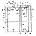
以下、図面に基づいて本発明の実施の形態を説明する。図1は、本実施形態における回転折れ戸を備えた扉設備全体の正面図、図2は、図1の実施形態における回転折れ戸の作用説明図、図3(a)は、図1の実施形態における連結部材のカバーの平面図、図3(b)は、同カバーの底面図、図3(c)は、同カバーの使用状態を説明するための一部を切欠いた概略説明図、図3(d)は、図3(a)のAA線断面図である。 Hereinafter, embodiments of the present invention will be described with reference to the drawings. FIG. 1 is a front view of an entire door facility provided with a rotary folding door in the present embodiment, FIG. 2 is an operation explanatory view of the rotary folding door in the embodiment of FIG. 1, and FIG. 3 (a) is an implementation of FIG. FIG. 3B is a bottom view of the cover, FIG. 3C is a schematic explanatory view with a part cut away for explaining a use state of the cover, FIG. 3 (d) is a cross-sectional view taken along line AA in FIG. 3 (a).
図1において、回転折れ戸の基本構造は、回転折れ戸3が、第1の扉5と第2の扉4との組合せからなり、これら第1の扉5と第2の扉4とが、それらの片側において折り畳み自在に連結されている。そして、これら両扉4、5が、縦長の門型扉枠体2に取り付けられている。
In FIG. 1, the basic structure of the rotary folding door is that the
そして、第1の扉5と第2の扉4との連結部を押すことにより、第2の扉4が連結部と反対側の上下端部を回転の中心として回転し、第1の扉5が、所定の個所において回転しつつ、扉枠体2に設けられたレールに沿って走行して、第1の扉5と第2の扉4とが、それらの連結部を手前側もしくはこれと反対側に突出させつつ、相互に折り畳まれて、第1の扉5が第2の扉4側に引き寄せられることにより、扉が開放されるようになっている。
And by pushing the connection part of the
扉枠体2は、左右の縦枠体8、8と、これら左右の縦枠体8、8に両端が固着されて一体化された上枠体9とからなっている。
The
縦枠体8は、図2に図示されているように、細長い内部折曲片8aと外部折曲片8bとの間に柱部材8cを挟んだ構造に形成されていて、内部折曲片8aは、その幅方向の先端が内方に直角にわずかに折曲され、底面が両側にわずかの幅を残して内方にわずかに窪まされた断面形状をなしている。そして、形成された凹部8dが、内方に向くようにして配置され、これら両縦枠体8、8の凹部8dに、第1の扉5および第2の扉4の幅方向、外方端面が、それぞれ部分的に受容されるようになっている。
As shown in FIG. 2, the
また、上枠体9の下部には、吊りレール部材10が取り付けられている。該吊りレール部材10の下部の内面は幅方向の両側に所定幅の間隙を設けてレール10a、10aが形成され、後述する第1の扉5の上面に固着された吊持軸35が扉枠体2の左右幅方向に走行可能なように、レール10a、10a間には、レール10a、10aの間隙による細長い開口10bが形成されている。
A
また、吊りレール部材10内には、扉枠体2の縦枠体8側の端部付近に両扉4、5が閉まるときに吊持軸35を介して第1の扉5を移動させる移動体として吊持軸35が固定された四輪の上吊車36の一部にピストンロッド19の先端19aが当接すると第1の扉5の閉止速度を減速するエアーダンパー18が取付けられている。
Further, in the
第2の扉4は、本体部をなす扉部材11の上面および下面に一端に円弧状の切り欠き4bを形成した横補強枠4a,4aが固着され、その右側面には、第2の扉4を回転可能に支持する回転軸を収納する半円筒状の長尺なカバー部材15が取付けられ、左側面に、半円筒状の長尺なカバー部材50が取付けられている。カバー部材50は、第2の扉4に連結される第1の扉5との間の隙間を塞ぐ(または、狭くする)ために取付けられるものである。
The
また、第1の扉5は、本体部をなす扉部材12の上面および下面に一端に円弧状の切り欠き5bを形成した横補強枠5a,5aが固着され、その右側面に、第1の扉5に連結される第2の扉4との間の隙間を塞ぐ(または、狭くする)半円筒状の長尺なカバー部材50が取付けられ、左側面には、第1の扉5を扉枠体2の縦枠体8に当接(または近接)させた際の隙間を塞ぐ(または、狭くする)断面半円弧状の長尺なカバー部材16が取付けられている。カバー部材16内と、カバー部材16に当接(または近接)する側の縦枠体8内には、それぞれ棒磁石17が収納され、回転折れ戸3を閉じて、第1の扉5を扉枠体2の縦枠体8に当接させると、その状態を維持するように構成されている。第2の扉4の本体部をなす扉部材11および第1の扉5の本体部をなす扉部材12は、細長い長方形の平板形状をなしている。扉部材11、12は、金属製もしくは合成樹脂製とされるが、木質製とされる場合もある。
Further, the
なお、扉部材11の上面および下面に横補強枠4a,4aを固着せずに、扉部材11だけで第2の扉4を形成したり、同様に、扉部材12の上面および下面に横補強枠5a,5aを固着せずに、扉部材12だけで第1の扉5を形成することもできる。
Note that the second reinforcing
第2の扉4の本体部をなす扉部材11の右側上端部には、垂直方向に回転軸を有するヒンジ30が埋設して取付けられている。また、ヒンジ30の上部は、扉枠体2の吊りレール部材10にブラケット31を介してネジにより固着されている。
A
また、扉部材11の右側下端部には円筒状のヒンジ32が埋設されている。ヒンジ32の筒内には回転軸33が嵌合されており、扉部材11は、回転軸33に回転自在に支持されている。回転軸33は、図示しないスラストベアリングに植設されており、スラストベアリングは、扉枠体2の右側縦枠体8に取り付けられたL字状ブラケット34の水平折曲部上に固着されている。したがって第2の扉4の荷重は、スラストベアリングの回転軸の植設面により受けられる。これにより第2の扉4は、扉枠体2の右端部に回転自在に支持されている。
A
第1の扉5の本体部をなす扉部材12は、その幅方向中央付近の位置、丁度、第2の扉4の回転半径相当の位置において、その上面が扉枠体2の吊りレール部材10に回転自在に吊持され、また、その右側の第2の扉4との連結部側上下端部が、第2の扉4の左側上下端部と相互に折り畳み自在に連結されて支持されることにより、扉枠体2に取り付けられている。
The
第1の扉5の上面が扉枠体2の吊りレール部材10に回転自在に吊持される部分の構造は、次のようになっている。第1の扉5の本体部をなす扉部材12の上面には、吊持軸35が固着されて取り付けられている。吊持軸35は、四輪の上吊車36の台板37の中央部に形成された軸受孔38を貫通して、そこに抜け止めされて回転可能に支持されている。したがって、第1の扉5は、吊持軸35を介して上吊車36により吊持されるとともに、上吊車36の軸受孔38に支持されて、回転可能である。
The structure of the portion in which the upper surface of the
上吊車36は、その台板37に回転自在に取り付けられた車輪39が、レール10a、10a上を転動するので、このレール10a、10aに沿って走行が可能である。その走行範囲は、回転扉3が閉鎖状態にあり、エアーダンパー18にピストンロッド19が収納されているときのピストンロッド19の先端19a近傍の位置から、回転扉3が完全に開放されたときの上枠体9の右端近傍の位置までである。
Since the
次に、第1の扉5の右側上下端部が、第2の扉4の左側上下端部と相互に折り畳み自在に連結される部分の構造を説明する。先ず、第1の扉5と第2の扉4を折畳み可能に連結する連結部材40について説明する。連結部材40は、平板状の連結板41の片面から所定の間隔で2本の連結軸42、42が突出し、これら連結軸42、42に同一寸法の一対の歯車部材(図では、歯45が半円周部に沿って形成された平歯車を採用している)43、43の軸孔43aが嵌合されて、一対の歯車部材43、43が回転可能に支持され、相互に噛み合うように構成されている。また、各歯車部材43、43には、軸孔43aを挟んで一対のネジ止め用の孔43b、43bが設けられている。なお、連結板41には、後述する歯車カバー46を取付るための一対のネジ止め用の孔41a、41aが設けられている。
Next, the structure of a portion in which the upper right and lower ends of the
第2の扉4の本体部をなす扉部材11の連結側の縦辺に位置する左の側面と、第1の扉5の本体部をなす扉部材12の連結側の縦辺に位置する右の側面には、扉部材11、12の縦辺の長さを有する縦長の金属性の扉連結用枠部材20、20が扉部材11、12の縦辺に沿って取り付けられている。
The left side surface located on the vertical side on the connection side of the
扉連結用枠部材20、20の外側部には、半円筒状の外周面を有するカバー部材50、50が嵌め込まれて張設されている。また、扉連結用枠部材20、20およびカバー部材50、50の上下の端面には、連結部材40、40が各一対の歯車43、43を扉連結用枠部材20、20に、それぞれ孔43b、43bにネジを挿入して取り付けられている。こうして連結部材40、40が扉連結用枠部材20、20の上下の端面に固定されることで、扉部材11、12は、これらに取付けられた扉連結用枠部材20、20を介して、第1の扉5の右側上下端部が、第2の扉4の左側上下端部に連結され、これにより第1の扉5と第2の扉4とが相互に折り畳み可能に構成されている。
そして、これら連結部材40、40には、外観がメガネ型形状で、上面が開口した箱状の歯車カバー46、46が被せられて取付けられている。歯車カバー46の底面には、連結部材40の連結板41の周囲を囲むように環状リブ48aが成形されており、環状リブ48aの内部は連結板41の収納部48となっている。また、歯車カバー46の底面の縁部には円弧状をした水抜き用のスリット47が断続的に形成されている。収納部48には、連結板41を収納したときに、連結板41に設けられたネジ止め用の孔41a、41aと、合致する位置に孔49、49が形成され、また、連結軸42、42と、合致する位置に孔49a、49aが形成されている。そして歯車カバー46は、これらの孔49a、49aに連結軸42、42を嵌合するとともに、孔49、49にネジを挿入して連結板41にネジ止めして、連結部材40に取付けられている。
The connecting
なお、この状態では、歯車43、43と扉連結用枠部材20、20との接合部はカバー部材50、50の上下の端面に接触しているが、メガネ型形状の歯車カバー46、46はカバー部材50、50の上下の端面との間に所定の間隙を有しており、第1の扉5と第2の扉4とが折り畳まれる際に歯車カバー46は、カバー部材50、50および扉部材11、12と接触しないように配置されている。
In this state, the joints between the
歯車カバー46、46が連結部材40、40に取付けられて、扉連結用枠部材20、20の上下の端面に固定される際には、第1の扉5の右側上下端部の横補強枠5aの一端の円弧状の切り欠き5bと第2の扉4の左側上下端部の横補強枠4aの一端の円弧状の切り欠き4bとの間に円弧状の間隙を有しており、第1の扉5と第2の扉4とが折り畳まれる際に、第1の扉5と第2の扉4とは、横補強枠4a、5aの各円弧状の切り欠き4b、5bはメガネ型形状の歯車カバー46との間に円弧状の間隙を保って回動するので、歯車カバー46は、横補強枠4a,5aと接触することはない。
When the gear covers 46, 46 are attached to the connecting
次に、扉連結用枠部材20とカバー部材50との接合構造の実施例1〜3について、図4〜図6を参照してさらに詳細に説明する。図4(a)は、実施例1の扉連結用枠部材20とカバー部材50の概略説明図、図4(b)は、実施例1の扉連結用枠部材20とカバー部材50の係合構造の概略図、図5(a)は、実施例2の扉連結用枠部材20aとカバー部材50aの概略説明図、図5(b)は、実施例2の扉連結用枠部材20aとカバー部材50aの概略説明図、図6は、実施例3の概略説明図である。
Next, Examples 1 to 3 of the joint structure between the door connecting
図4(a)に実施例1の連結部を構成する扉連結用枠部材20とカバー部材50を示す。扉連結用枠部材20は金属または樹脂等により形成されたもので、外側に開口21を有する断面コ字状の取付溝部22を有しており、開口21内に第2の扉4の扉部材11(または、第1の扉5の扉部材12)の連結側の縦辺に位置する側面が嵌め込まれ、ネジにより扉部材11に取付けられている。取付溝部22の開口21の裏面には、扉連結用枠部材20の幅方向の外側に高さの低い突条23が設けられ、その内側に突条23と略同じ高さの低い突条24が設けられ、さらに内側に高さの高い突条25が、間隔を空けて幅方向に対称に向かい合って、それぞれ1対ずつ並行して縦辺に沿って設けられている。
FIG. 4A shows the door connecting
高さの高い1対の突条25、25の間に位置する開口21の裏面には、断面がC字状のリブ26で形成された溝部27が外側に開口28を有して設けられている。一対の突条25、25の先端は、歯車43を取付けるための一対のネジ止め用の孔41b,41bを有する断面C字状のネジ受け部26a,26aを形成してリブ26の外側に接続されている。突条25は、上記のネジ受け部26aの位置より先に伸びて、その先端は折り返されて、間隔を空けて高さの低い突条24との間に開口を有して向かい合うように設けられている。これにより、高さの高い突条25の一部を底面として、高い突条25の折り返された先端部25aと低い突条24とが係止壁を形成して外側に開口24aを有する溝状のフック受け部29が縦辺に沿って長尺に形成されている。なお、突条24と突条25aの先端部は、尖って外側に広がるテーパ状に形成されている。
On the back surface of the
カバー部材50は、ゴムまたは樹脂等の弾力性のある素材により成形されたもので、内側に開口51を有する略半円筒状であり、半円筒の内部には外周に沿って厚みを持たせたC字状の補強用リブ52が形成されている。リブ52の内面には、端部側に突条53が設けられ、その内側に突条54が、間隔を空けて中央付近から対称に、それぞれ1対ずつ設けられている。また、カバー部材50の開口51の内面の両端縁には、先端に係止部55aを有して半円筒の中心に向かって所定長さ突出した断面T字状のフック55、55が、長尺に設けられている。カバー部材50の半円筒の外周には、中心付近から突出して端縁側に下降する断面円弧状をした1本の係合用突条57が縦辺に沿って長尺に設けられていて、閉扉時、両係合用突条57、57が係合して、扉が密閉される。
The
扉連結用枠部材20のフック受け部29、29にカバー部材50のフック55、55を係合すると、図4(b)に示すようにカバー部材50のC字状の補強用リブ52の内面に設けた1対の突条53、53が扉連結用枠部材20のC字状のリブ26の外周面に当接し、この状態で1対の突条54、54がリブ26の開口28付近の両端部の外周面に当接し、フック受け部29にフック55が嵌合し、フック55は突条23により挿入できる位置が規制され、また、突条24からなる係止壁と係止壁25aにより係止部55aが抜け止めされて、カバー部材50はC字状のリブ26に略同軸に固定され、半円筒の外周が180度を大きく超えた範囲が巻きついた状態で扉連結用枠部材20に一体に接合される。
When the
図5(a)に実施例2の連結部を示す。実施例2では、扉連結用枠部材20aのフック受け部60の形状と、カバー部材50aのフック56の形状、および半円筒の外周に設けられる1本の突条57aの形状が実施例1のものと異なるが、その他の構造は同じである。
FIG. 5A shows the connecting portion of the second embodiment. In the second embodiment, the shape of the
扉連結用枠部材20aは、実施例1の扉連結用枠部材20と同様に、外側に開口21を有する断面コ字状の取付溝部22を有している。取付溝部22の両縁部分は開口21の裏面に延長する一対の突条61、61となっている。また、取付溝部22の開口21の裏面には、断面がC字状のリブ26で形成された溝部27が外側に開口28を有して設けられている。一対の突条61、61は途中から中心方向に略直角に折れ曲がり、その折曲部62の端部側に段部62aを有して、折曲部62の先端部分が、歯車43を取付けるための一対のネジ止め用の孔41c,41cを有する断面C字状の一対のネジ受け部63,63を形成してリブ26に接続されている。リブ26の外周面には、折曲部62との間に間隔を有して並行に向かい合うように突条64が設けられている。この突条64は、折曲部62と共に溝を形成し、さらに突条64の先端部は途中から折曲部62に向かって略直角に折れ曲がり、上記溝の上部に係止壁65を形成して外側に開口66を有する鉤状のフック受け部60を形成している。このフック受け部60は縦辺に沿って長尺に形成されている。
Similarly to the door connecting
カバー部材50aは、内側に開口51を有する略半円筒状であり、半円筒の内部には外周に沿って厚みを持たせたC字状の補強用リブ52が形成されている。C字状の補強用リブ52の内面には、端部側に突条53が設けられ、その内側に突条54が、間隔を空けて中央付近から対称に、それぞれ1対ずつ設けられている。また、カバー部材50aの開口51の内面の両端縁には先端に係止部56aを有して半円筒の中心に向かって所定長さ突出した断面L字状のフック56、56が、縦辺に沿って長尺に設けられている。カバー部材50aの半円筒の外周には、中心付近から突出して端縁側に下降する断面鋭角状をした1本の突条57aが縦辺に沿って長尺に設けられていて、閉扉時、両係合用突条57a、57aが係合して、扉が密閉される。
The
扉連結用枠部材20aのフック受け部60、60にカバー部材50aのフック56、56を係合すると、図5(b)に示すようにカバー部材50aのC字状の補強用リブ52の内面に設けた1対の突条53、53が扉連結用枠部材20aのC字状のリブ26の外周面に当接し、この状態で1対の突条54、54がリブ26の開口28付近の両端部の外周面に当接し、フック受け部60にフック56が嵌合し、フック56は段部62aにより挿入できる位置が規制され、また、係止壁65により係止部56aが抜け止めされて、カバー部材50aはC字状のリブ26に略同軸に固定され、半円筒の外周が180度までの範囲が巻きついた状態で扉連結用枠部材20aに一体に接合される。
When the
図6に実施例3の連結部を示す。図6において、カバー部材50bの半円筒の外周には、中心付近から所定長さ突出した板状をした1本の係合用突条57bが縦辺に沿って長尺に設けられている。実施例3では、この係合用突条57bの形状が実施例2のものと異なるが、その他の構造は実施例2同じであるので、その説明は省略する。
FIG. 6 shows a connecting portion of the third embodiment. In FIG. 6, on the outer periphery of the semi-cylinder of the
以上説明したように、本発明の回転折れ戸によれば、カバー部材と扉連結用枠部材は、係合すると前記フック受け部に前記フックが嵌合し、前記係止壁により前記係止部が抜け止めされて、前記カバー部材は前記扉連結用枠部材のリブに略同軸に固定され、半円筒の外周が巻きついた状態で前記扉連結用枠部材に一体に接合されて、前記係合状態を維持する係合構造を有するので、第1の扉および第2の扉の各カバー部材は扉連結用枠部材との間に隙間が生じても扉連結用枠部材に嵌め込まれた状態では、扉連結用枠部材から外れることはない。 As described above, according to the rotary folding door of the present invention, when the cover member and the door connecting frame member are engaged, the hook is fitted to the hook receiving portion, and the locking portion is formed by the locking wall. The cover member is fixed substantially coaxially to the rib of the door connecting frame member, and is integrally joined to the door connecting frame member with the outer periphery of the semi-cylinder wound around, Since it has the engagement structure that maintains the combined state, each cover member of the first door and the second door is fitted in the door connecting frame member even if a gap is formed between the door connecting frame member Then, it does not come off from the frame member for door connection.
カバー部材50、50a、50bは、それぞれ半円筒の外周が扉連結用枠部材20に180度内外の範囲が巻きついた状態で一体に接合されるから、人が誤って手や足の指を挟んでしまった場合でもクッション効果があり安全性に配慮されている。特に実施例1のカバー部材50は、半円筒の外周が扉連結用枠部材20に180度を大きく超えた範囲が巻きついた状態で一体に接合されているので、クッション効果が最も大きく安全性の高いものである。
The
また、連結部材には、一対の歯車を受け入れる開口が設けられた歯車カバーが取付けられているので、一対の歯車に子供が手や足の指を挟んでしまうことはなく安全である。 Moreover, since the gear cover provided with the opening which receives a pair of gears is attached to the connection member , a child does not pinch a hand or a toe between a pair of gears , and it is safe.
2 扉枠体
3 回転折れ戸
4 第2の扉
4a,5a 横補強枠
5 第1の扉
8 縦枠体
8a 内部折曲片
8b 外部折曲片
8c 柱部材
8d 凹部
9 上枠体
10 吊りレール部材
10a レール
11,12 扉部材
15,16,50,50a カバー部材
17 棒磁石
20,20a 扉連結用枠部材
21,24a,28,51,66 開口
22 取付溝部
23,24,25,53,54,61,64 突条
25a,65 係止壁
26 リブ
26a,63 ネジ受け
27 溝部
29,60 フック受け部
30,32 ヒンジ
31 ブラケット
33 回転軸
34 L字状ブラケット
35 吊持軸
36 上吊車
37 台板
38 軸受孔
39 車輪
40 連結部材
41 連結板
41a,41b,41c,43b,49 孔
42 連結軸
43 歯車
43a 軸孔
45 歯
46 歯車カバー
47 スリット
48 収納部
48a 環状リブ
52 補強用リブ
55,56 フック
55a,56a 係止部
57,57a, 係合用突条
62 折曲部
62a 段部
DESCRIPTION OF
Claims (4)
前記扉連結用枠部材は、前記扉の連結側の縦辺に位置する側面が嵌め込まれて取付けられる取付溝部を有し、前記取付溝部の裏面に1対の突条が幅方向に対称に前記縦辺に沿って設けられ、前記1対の突条の間にリブが設けられるとともに、前記各突条の先端は折り返されて係止壁を形成して外側に開口を有する溝状のフック受け部が縦辺に沿って形成されてなり、
前記カバー部材は、内側に開口を有する半円筒状であって、前記開口の内面の両端縁に、先端に係止部を有して半円筒の中心に向かって所定長さ突出したフックが設けられてなり、
前記カバー部材と前記扉連結用枠部材は、係合すると前記フック受け部に前記フックが嵌合し、前記係止壁により前記係止部が抜け止めされて、前記カバー部材は前記扉連結用枠部材のリブに略同軸に固定され、半円筒の外周が巻きついた状態で前記扉連結用枠部材に一体に接合されて、前記係合状態を維持する係合構造を有することを特徴とする回転折れ戸。 The first door and the second door are foldably connected to each other via a connecting member having a pair of gear members in which shaft holes are fitted to the two connecting shafts and mesh with each other. A vertically long door connecting frame member is configured to be rotatable about each connecting shaft, and is attached along the vertical side of the connecting side of the first door and the second door, and the outside of the door connecting frame member. In a rotary folding door in which a cover member having a semi-cylindrical outer peripheral surface is fitted and stretched,
The door connecting frame member has a mounting groove portion to which a side surface positioned on the vertical side of the connecting side of the door is fitted and attached, and a pair of protrusions are symmetrically arranged in the width direction on the back surface of the mounting groove portion. A groove-shaped hook receiver that is provided along the vertical side and that is provided with ribs between the pair of protrusions, and that the ends of the protrusions are folded back to form locking walls and have openings on the outside. The part is formed along the vertical side,
The cover member has a semi-cylindrical shape having an opening on the inner side, and hooks having a locking portion at the tip and projecting a predetermined length toward the center of the semi-cylinder are provided at both ends of the inner surface of the opening. Being
When the cover member and the door connecting frame member are engaged, the hook is fitted to the hook receiving portion, the locking portion is prevented from being detached by the locking wall, and the cover member is used for the door connecting It is fixed substantially coaxially to the rib of the frame member, and has an engagement structure that is integrally joined to the door connecting frame member in a state where the outer periphery of the semi-cylinder is wound, and maintains the engagement state. Rotating folding door.
Priority Applications (1)
| Application Number | Priority Date | Filing Date | Title |
|---|---|---|---|
| JP2004266158A JP4122322B2 (en) | 2004-09-14 | 2004-09-14 | Rotating folding door |
Applications Claiming Priority (1)
| Application Number | Priority Date | Filing Date | Title |
|---|---|---|---|
| JP2004266158A JP4122322B2 (en) | 2004-09-14 | 2004-09-14 | Rotating folding door |
Publications (3)
| Publication Number | Publication Date |
|---|---|
| JP2006083513A JP2006083513A (en) | 2006-03-30 |
| JP2006083513A5 JP2006083513A5 (en) | 2007-06-28 |
| JP4122322B2 true JP4122322B2 (en) | 2008-07-23 |
Family
ID=36162253
Family Applications (1)
| Application Number | Title | Priority Date | Filing Date |
|---|---|---|---|
| JP2004266158A Active JP4122322B2 (en) | 2004-09-14 | 2004-09-14 | Rotating folding door |
Country Status (1)
| Country | Link |
|---|---|
| JP (1) | JP4122322B2 (en) |
Cited By (1)
| Publication number | Priority date | Publication date | Assignee | Title |
|---|---|---|---|---|
| KR20190068701A (en) * | 2017-12-09 | 2019-06-19 | 장영근 | Folding swing door unit with narrow radius of rotation |
Families Citing this family (1)
| Publication number | Priority date | Publication date | Assignee | Title |
|---|---|---|---|---|
| JP4995680B2 (en) * | 2007-09-19 | 2012-08-08 | 三和シヤッター工業株式会社 | Door equipment |
-
2004
- 2004-09-14 JP JP2004266158A patent/JP4122322B2/en active Active
Cited By (2)
| Publication number | Priority date | Publication date | Assignee | Title |
|---|---|---|---|---|
| KR20190068701A (en) * | 2017-12-09 | 2019-06-19 | 장영근 | Folding swing door unit with narrow radius of rotation |
| KR102015421B1 (en) * | 2017-12-09 | 2019-08-28 | 이준우 | Folding swing door unit with narrow radius of rotation |
Also Published As
| Publication number | Publication date |
|---|---|
| JP2006083513A (en) | 2006-03-30 |
Similar Documents
| Publication | Publication Date | Title |
|---|---|---|
| JP4412677B2 (en) | Rotating folding door | |
| JP4928311B2 (en) | Vehicle door and manufacturing method thereof | |
| EP2607128A2 (en) | Seal member of automobile door | |
| JP4122322B2 (en) | Rotating folding door | |
| JP3581995B2 (en) | Double hinge structure and lid mounting structure | |
| JP2006083513A5 (en) | ||
| JP4863293B2 (en) | Curtain wall panel unit | |
| KR101769180B1 (en) | Structure reinforcement assembly for fittings | |
| KR100781943B1 (en) | A flat-type torque hinge | |
| JP2012036585A (en) | Door | |
| JP5748283B2 (en) | container | |
| US982633A (en) | Fastening device for doors, windows, and the like. | |
| JP2019100649A (en) | refrigerator | |
| JPH0861831A (en) | Door structure of refrigerator | |
| JP2011020612A (en) | Glass run | |
| CN215362366U (en) | Corner structure of external box reinforcing frame and external box reinforcing frame | |
| KR200369502Y1 (en) | plain slat structure of panel shutter | |
| JP2008100555A (en) | Mounting structure of weather strip for automobile | |
| KR200359283Y1 (en) | window handle to superior application | |
| JP2012026140A (en) | Fittings | |
| JPH033732Y2 (en) | ||
| EP2992155B1 (en) | An operating and locking assembly, and a method of providing a condition of use of a window with such an operating and locking assembly | |
| JP3999142B2 (en) | Joinery | |
| JP2007023617A (en) | Window frame and window equipped with the same | |
| JP2009046939A (en) | Side ditch lid and closed lid structure of concrete side ditch block by the same |
Legal Events
| Date | Code | Title | Description |
|---|---|---|---|
| A521 | Request for written amendment filed |
Free format text: JAPANESE INTERMEDIATE CODE: A523 Effective date: 20070514 |
|
| A621 | Written request for application examination |
Free format text: JAPANESE INTERMEDIATE CODE: A621 Effective date: 20070514 |
|
| A977 | Report on retrieval |
Free format text: JAPANESE INTERMEDIATE CODE: A971007 Effective date: 20071207 |
|
| A131 | Notification of reasons for refusal |
Free format text: JAPANESE INTERMEDIATE CODE: A131 Effective date: 20071218 |
|
| A521 | Request for written amendment filed |
Free format text: JAPANESE INTERMEDIATE CODE: A523 Effective date: 20080215 |
|
| TRDD | Decision of grant or rejection written | ||
| A01 | Written decision to grant a patent or to grant a registration (utility model) |
Free format text: JAPANESE INTERMEDIATE CODE: A01 Effective date: 20080401 |
|
| A61 | First payment of annual fees (during grant procedure) |
Free format text: JAPANESE INTERMEDIATE CODE: A61 Effective date: 20080501 |
|
| FPAY | Renewal fee payment (event date is renewal date of database) |
Free format text: PAYMENT UNTIL: 20110509 Year of fee payment: 3 |
|
| R150 | Certificate of patent or registration of utility model |
Ref document number: 4122322 Country of ref document: JP Free format text: JAPANESE INTERMEDIATE CODE: R150 Free format text: JAPANESE INTERMEDIATE CODE: R150 |
|
| FPAY | Renewal fee payment (event date is renewal date of database) |
Free format text: PAYMENT UNTIL: 20110509 Year of fee payment: 3 |
|
| FPAY | Renewal fee payment (event date is renewal date of database) |
Free format text: PAYMENT UNTIL: 20120509 Year of fee payment: 4 |
|
| R250 | Receipt of annual fees |
Free format text: JAPANESE INTERMEDIATE CODE: R250 |
|
| FPAY | Renewal fee payment (event date is renewal date of database) |
Free format text: PAYMENT UNTIL: 20130509 Year of fee payment: 5 |
|
| R250 | Receipt of annual fees |
Free format text: JAPANESE INTERMEDIATE CODE: R250 |
|
| FPAY | Renewal fee payment (event date is renewal date of database) |
Free format text: PAYMENT UNTIL: 20130509 Year of fee payment: 5 |
|
| R250 | Receipt of annual fees |
Free format text: JAPANESE INTERMEDIATE CODE: R250 |
|
| R250 | Receipt of annual fees |
Free format text: JAPANESE INTERMEDIATE CODE: R250 |
|
| R250 | Receipt of annual fees |
Free format text: JAPANESE INTERMEDIATE CODE: R250 |
|
| R250 | Receipt of annual fees |
Free format text: JAPANESE INTERMEDIATE CODE: R250 |
|
| R250 | Receipt of annual fees |
Free format text: JAPANESE INTERMEDIATE CODE: R250 |
|
| R250 | Receipt of annual fees |
Free format text: JAPANESE INTERMEDIATE CODE: R250 |
|
| R250 | Receipt of annual fees |
Free format text: JAPANESE INTERMEDIATE CODE: R250 |
|
| R250 | Receipt of annual fees |
Free format text: JAPANESE INTERMEDIATE CODE: R250 |
|
| R250 | Receipt of annual fees |
Free format text: JAPANESE INTERMEDIATE CODE: R250 |
|
| R250 | Receipt of annual fees |
Free format text: JAPANESE INTERMEDIATE CODE: R250 |
|
| R250 | Receipt of annual fees |
Free format text: JAPANESE INTERMEDIATE CODE: R250 |