JP4119533B2 - Electronic camera and control method thereof - Google Patents
Electronic camera and control method thereof Download PDFInfo
- Publication number
- JP4119533B2 JP4119533B2 JP18808898A JP18808898A JP4119533B2 JP 4119533 B2 JP4119533 B2 JP 4119533B2 JP 18808898 A JP18808898 A JP 18808898A JP 18808898 A JP18808898 A JP 18808898A JP 4119533 B2 JP4119533 B2 JP 4119533B2
- Authority
- JP
- Japan
- Prior art keywords
- tilt
- image
- subject
- solid
- electronic camera
- Prior art date
- Legal status (The legal status is an assumption and is not a legal conclusion. Google has not performed a legal analysis and makes no representation as to the accuracy of the status listed.)
- Expired - Fee Related
Links
Images


Description
【0001】
【技術分野】
この発明は,被写体を撮像し,被写体像を表す画像データを出力する電子カメラおよびその制御方法に関する。
【0002】
【発明の背景】
写真フイルムに被写体像を記録するいわゆる銀塩カメラには蛇腹の先端に撮像レンズを保持しているものがある。このようなカメラでは,ユーザが手で蛇腹を動かし写真フイルムの結像面上における光軸と撮像レンズの光軸とをずらすこと(あおり補正)により異なる距離にある複数の被写体のピントを合わせることができる。
【0003】
固体電子撮像素子を用いて被写体を撮像する電子カメラにおいては,撮像素子を傾斜させてあおりを行うものも実現されている(特開平9-331476号)が,任意の方向にあおり補正を行うことはできない。
【0004】
また,電子カメラにおいてあおり補正を行った場合に,撮像範囲内においてどの部分が合焦しているかを確認することが困難な場合がある。
【0005】
さらに,被写体像を表すディジタル画像データを得ることができる,という電子カメラの特性を考慮して機械的なあおりと同様な効果を得る(いわゆる電子的なあおり補正)ようにすることも要望されている。
【0006】
【発明の開示】
この発明は,任意の方向にあおり補正を行うことができる電子カメラを提供することを目的とする。
【0007】
また,この発明は,あおり補正を行った場合に撮像範囲内における合焦範囲を確認できるようにすることを目的とする。
【0008】
さらに,この発明は,いわゆる電子的なあおり補正を行うことができるようにすることを目的とする。
【0009】
第1の発明による電子カメラは,受光面に被写体像が結像することにより被写体像を表す画像データを出力する固体電子撮像素子,上記受光面が,傾斜自在になるように上記固体電子撮像素子を支持する固体電子撮像素子支持機構,あおり角およびあおり方向をそれぞれ検出するあおり検出手段,ならびに上記あおり検出手段により検出されたあおり角およびあおり方向にもとづいて,上記固体電子撮像素子支持機構を制御するあおり制御手段を備えたことを特徴とする。
【0010】
第1の発明は,上記電子カメラに適した方法も提供している。すなわち,受光面に被写体像が結像することにより被写体像を表す画像データを出力する固体電子撮像素子の上記受光面が,傾斜自在になるように上記固体電子撮像素子を支持しておき,あおり角およびあおり方向をそれぞれ検出し,検出されたあおり角およびあおり方向にもとづいて,上記固体電子撮像素子の支持を制御するものである。
【0011】
第1の発明によると,上記固体電子撮像素子の受光面が傾斜自在になるように上記固体電子撮像素子が支持されている。上記あおり検出手段によって上記あおり角およびあおり方向が検出されると,検出されたあおり角およびあおり方向にもとづいて上記固体電子撮像素子の支持が制御される(たとえばあおり角と同じ角度または大きい角度もしくは小さい角度だけ,あおり方向と同じ方向に傾斜するように固体電子撮像素子の支持が制御される)。
【0012】
上記固体電子撮像素子の受光面が任意の傾斜となるようにあおられる。
【0013】
上記電子カメラが,被写体を上記固体電子撮像素子の受光面上に結像する撮像レンズを含む蛇腹ユニットをさらに備えているときには,ユーザは,上記あおりユニットを操作する。この操作にもとづいて上記あおり角およびあおり方向が検出される。また,あおり角およびあおり方向を入力する入力手段を設け,入力されたあおり角およびあおり方向にもとづいて上記固体電子撮像素子の受光面が任意の傾斜となるように上記固体電子撮像素子の支持が制御されてもよい。
【0014】
ストロボ発光装置,および上記ストロボ発光装置を発光させるための駆動電圧を充電するストロボ・コンデンサをさらに備えている電子カメラにおいては,上記あおり制御手段の駆動電圧が上記ストロボ・コンデンサから供給されるようにしてもよい。
【0015】
上記あおり制御手段の駆動電源を新たに設けることが不要となる。
【0016】
電子カメラ本体は小型化が要求されているため,電子カメラに備えられているモニタ表示装置の大きさもおのずから制限がある。このため,モニタ表示装置の解像度は低いことが多い。あおり補正を行って被写体を撮像しても合焦しているかどうか確認することが困難である。
【0017】
このため,上記固体電子撮像素子から出力される画像データによって表される被写体像を表示する表示装置,あおり確認指令を入力するあおり確認指令入力手段,および上記あおり確認指令入力手段から入力されたあおり確認指令に応答して,上記表示装置に表示されている被写体像の一部を拡大して表示するように上記表示装置を制御する表示制御手段をさらに備えてもよい。
【0018】
被写体像の一部を拡大できるので,拡大した部分が合焦しているかどうかが確認しやすくなる。
【0019】
第2の発明による電子カメラは,異なる焦点距離において同一の被写体を複数回撮像し,複数駒の被写体像を表す画像データを出力する撮像手段,上記撮像手段から出力される画像データによって表される複数駒の被写体像のそれぞれを上記複数駒数の各部分領域に分割し,それぞれの駒の被写体像における各部分領域のうち合焦している部分領域を表す部分領域画像データを抽出する部分領域画像データ抽出手段,および上記部分領域画像データ抽出手段によって抽出された部分領域画像データによって表される部分領域を組み合わせて,一駒の被写体像を表す合成画像データを生成して出力する画像合成手段を備えたことを特徴とする。
【0020】
第2の発明は,上記電子カメラに適した方法も提供している。すなわち,異なる焦点距離において同一の被写体を複数回撮像して,複数駒の被写体像を表す画像データを得,得られた画像データによって表される複数駒の被写体像のそれぞれを上記複数駒数の各部分領域に分割し,それぞれの駒の被写体像における各部分領域のうち合焦している部分領域を表す部分領域画像データを抽出し,抽出された部分領域画像データによって表される部分領域を組み合わせて,一駒の被写体像を表す合成画像データを生成して出力するものである。
【0021】
第2の発明によると,合焦している複数の上記各部分領域を用いて一駒の合成画像が得られる。得られた一駒の合成画像はすべての領域が合焦していることとなる。機械的なあおり補正をすることなく,電子的なあおりを実現することができる。
【0022】
第3の発明による電子カメラは,あおり角およびあおり方向をそれぞれ検出するあおり検出手段,被写体を撮像し,被写体像を表す画像データを出力する撮像手段,上記あおり検出手段によって検出されたあおり角およびあおり方向にもとづいて上記被写体像の領域ごとのエッジ強調量を算出するエッジ強調量算出手段,ならびに上記エッジ強調量算出手段によって算出されたエッジ強調量にもとづいて,上記撮像手段から出力された画像データによってあらわされる被写体像をエッジ強調するエッジ強調手段を備えたことを特徴とする。
【0023】
第3の発明は,上記電子カメラに適した方法も提供している。すなわち,あおり角およびあおり方向をそれぞれ検出し,被写体を撮像し,被写体像を表す画像データを得,検出されたあおり角およびあおり方向にもとづいて上記被写体像の領域ごとのエッジ強調量を算出し,算出されたエッジ強調量にもとづいて,撮像によって得られた画像データによって表される被写体像をエッジ強調するものである。
【0024】
第3の発明によると,上記あおり検出手段によりあおり角およびあおり方向がそれぞれ検出される。検出されたあおり角およびあおり方向にもとづいて上記被写体像の領域ごとのエッジ強調量が算出される。算出されたエッジ強調量にもとづいて被写体像を表す画像データがエッジ強調される。
【0025】
エッジ強調されているので,合焦せずにぼけている被写体像であっても合焦している被写体像として見える。
【0026】
【実施例の説明】
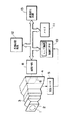
図1は,この実施例による電子カメラの電気的構成を示すブロック図である。電子カメラの全体の動作は,制御CPU10によって統括される。
【0027】
異なる距離にある複数の被写体を撮像するとき,すべての被写体にピントを合わせることは困難である。すべての被写体にピントが合った画像を得るためにあおり補正が行われる。電子カメラには,あおり補正を行うために,伸縮自在な蛇腹3が設けられている。
【0028】
蛇腹3の先端面2には撮像レンズ1が保持されている。ユーザは,蛇腹3の後端面4を上下,左右などに動かすことによりあおり角およびあおり方向を設定する。設定されたあおり角および方向にもとづいて,あおり補正が行なわれる。蛇腹3の先端面2を上下,左右に動かすことによりあおり角およびあおり方向を設定するようにしてもよい。
【0029】
蛇腹3の後端面4の動いた角度および動き方向(あおり角およびあおり方向)は,変位センサ5によって検出される。変位センサ5によって検出されたあおり角およびあおり方向を表すデータは,制御CPU10に入力する。
【0030】
変位センサ5は,ジョイスティックの傾斜角および傾斜方向を検出するセンサを適用することができる。ジョイスティックの傾斜角および傾斜方向を検出する場合と同様にして,蛇腹3の後端面4のあおり角およびあおり方向を検出する。
【0031】
撮像レンズ1によって被写体像がCCD6の受光面上に結像する。CCD6から被写体像を表す映像信号が出力され,撮像回路8に入力する。映像信号は,撮像回路8においてディジタル画像データに変換されて出力する。電子カメラにはそれぞれが一駒の画像を表す画像データを記憶できる第1の画像メモリ11Aから第4の画像メモリ11Dが含まれている。したがって電子カメラは,4駒の画像を表す画像データを一時的に記憶することができる。
【0032】
撮像回路8から出力される画像データは,第1の画像メモリ11Aに一時的に記憶される。もっともほかの画像メモリ11Bから11Dに記憶するようにしてもよい。第1の画像メモリ11Aに記憶された画像データは,第1の画像メモリ11Aから読み出され,画像再生装置13に入力する。画像データは,画像再生装置13において再生処理が行われ,表示装置20に入力する。表示装置20の表示画面上に撮像した被写体像が表示される。
【0033】
第1の画像メモリ11Aに一時的に記憶された画像データは,外部記憶装置12にも入力する。外部記憶装置12によって被写体像を表す画像データが記憶媒体(メモリ・カード,フロッピィ・ディスクなど)に記憶される。
【0034】
電子カメラは,ストロボ撮像が可能である。ストロボ撮像のためにストロボ発光装置15が設けられている。制御CPU10によってストロボ制御回路14が制御される。ストロボ制御回路14によってストロボ・コンデンサ16に充電された電荷が放電され,ストロボ発光装置15が発光する。ストロボ・コンデンサ16に蓄積された電荷は,圧電素子7を駆動するためにも用いられる。
【0035】
CCD6は,その四隅が圧電素子7によって傾斜自在に支持されている。圧電素子7は圧電素子制御回路9によって制御される。
【0036】
ユーザによって蛇腹3の後端面4が動かされると,あおり角およびあおり方向が変位センサ5によって検出される。検出されたあおり角およびあおり方向を表すデータは,変位センサ5から制御CPU10に入力する。制御CPU10によって圧電素子制御回路9が制御され,この圧電素子制御回路9によってCCD6の四隅を支持している圧電素子7が制御される。圧電素子7によってCCD6が傾斜させられ,あおり補正が実行されることとなる。
【0037】
変位センサ5によって検出されたあおり角およびあおり方向にもとづいて定められるCCD6の傾斜の程度は,ユーザが自在に設定することができる。たとえば,6X7フイルムのカメラにおいて蛇腹を動かしてあおり補正を行う場合と同様にしてもよいし,6X9フイルムのカメラにおいて蛇腹を動かしてあおり補正を行う場合と同様にしてもよい。
【0038】
上述した電子カメラにおいては,ユーザが蛇腹3の後端4を動かしてあおり角およびあおり方向を設定しているがあおり角およびあおり方向をユーザが入力するようにしてもよい。
【0039】
CCD6の画素ピッチが細密になるにつれて,CCD6の傾斜制御にミクロン・オーダの制御が必要となる。画素ピッチは,数μmであるため,CCD6での像面深度は,開放絞りがF2程度であれば,2×(数μm)=10μm程度である。圧電素子7を用いることにより高精度の制御が可能となる。
【0040】
圧電素子7は,制御するために100Vから200V程度の電圧を必要とする。上述のようにコンデンサ16にストロボ発光用の電荷が蓄積されているので,このコンデンサ16に蓄積されている電荷を圧電素子7の駆動電圧として用いることができる。これにより圧電素子7を駆動するための専用の電源が不要となる。
【0041】
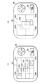
図2(A)および(B)は,表示装置20の表示画面の一例を示している。
【0042】
図2(A)を参照して,表示装置20の表示画面には画像表示領域21,あおり指令領域25およびあおり確認モード設定領域26が含まれている。
【0043】
画像表示領域21には,撮像によって得られる被写体像が表示される。図2(A)に示す例では,距離が異なる第1の被写体から第4の被写体があり,これらの第1の被写体から第4の被写体を撮像して,第1の被写体像OB1から第4の被写体像OB4が表示されている。第1の被写体から第4の被写体になるにつれ,序々に距離が近くなっている。第4の被写体像OB4が合焦しており,第1の被写体像OB1になるにつれぼけている。
【0044】
あおり指令領域25には上下左右の方向に4つの矢印が表示されている。これらの4つの矢印の中から所望の方向を表す矢印上をユーザがタッチすることによりあおり方向が指令として電子カメラに入力する。また,あおり指令領域25の矢印上をユーザがタッチしている時間が制御CPU10内のカウンタ(図示略)によって計測される。その矢印上をユーザがタッチしている時間にもとづいてあおり角が決定する。この矢印上をユーザがタッチしている時間が長ければ,あおり角が大きくなる。
【0045】
あおり指令領域25から入力されたあおり角およびあおり方向を表すデータは,制御CPU10に入力し,制御CPU10によって圧電素子制御回路9が制御される。圧電素子制御回路9によって圧電素子7が駆動され,CCD6が傾斜させられる。
【0046】
表示装置20の表示画面上のあおり確認モード設定領域26がユーザによってタッチされると,あおり確認モードが設定される。
【0047】
あおり確認モードとなると,図2(B)に示すように画像表示領域21は,5分割される。画像表示領域21には第1の画像拡大表示領域22A,第2の画像拡大表示領域22B,第3の画像拡大表示領域22C,第4の画像拡大表示領域22Dおよび第5の画像拡大表示領域22Eが含まれている。
【0048】
第1の画像拡大表示領域22Aは,図21(A)に示すように画像表示領域21に表示されている被写体像を16分割し,かつ中央にその16分割したときと同じ大きさの領域を形成したときに,画像表示領域21の左上隅の部分を含む第1の画像分割領域21Aを面積比4倍に拡大したものである。
【0049】
同様に,第2の画像拡大表示領域22Bは,画像表示領域21の左下隅の部分を含む第2の画像分割領域21Bを面積比4倍に拡大したものであり,第3の画像拡大表示領域22Cは,画像表示領域21の右上隅の部分を含む第3の画像分割領域21Cを面積比4倍に拡大したものであり,第4の画像拡大表示領域22Dは,画像表示領域21の右下隅の部分を含む第4の画像分割領域21Dを面積比4倍に拡大したものであり,第5の画像拡大表示領域22Eは,画像表示領域21の中央の部分を含む第5の画像分割領域21Eを面積比約4倍に拡大したものである。
【0050】
電子カメラの大きさの制約から,電子カメラに備えられている表示装置の表示画面は一般的に小さい。したがって表示装置の解像度も低く,被写体像が合焦しているか確認することが難しい。この実施例による電子カメラにおいては,あおり確認モードとなると,表示画面の表示領域の一部が拡大して表示されるので,被写体像が合焦しているかを確認するのが比較的容易となる。
【0051】
図2(B)においては,5分割表示されているが,5分割表示に限らず,そのほかの分割方法にしたがって表示してもよい。また,画像表示領域21を分割表示せずに,画像表示領域21の一部を画像表示領域21の全面に拡大表示するようにしてもよい。
【0052】
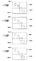
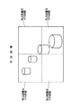
図3から図5は,他の実施例を示すものである。図3は,電子カメラの電気的構成を示すブロック図,図4(A),(B),(C)および(D)は,被写体像の一例を示し,図5は図3に示す電子カメラによって得られる合成画像の一例を示している。
【0053】
図3において,図1に示すものと同一物には同一符号を付して説明を省略するる。
【0054】
図3に示す電子カメラにおいては,蛇腹3は設けられていない。CCD6の前方には,撮像レンズ・ユニット(図示略)を含む鏡筒30が設けられている。また,撮像レンズ・ユニットを駆動するためのモータ18が設けられている。このモータ18は,モータ制御回路17によって駆動させられる。
【0055】
モータ18によって撮像レンズ・ユニットが複数の異なる焦点距離で合焦するように駆動させられ,それぞれの焦点距離で同一の被写体像が撮像される。
【0056】
この実施例では,焦点距離A,焦点距離B,焦点距離Cおよび焦点距離Dにおいて第1回目の撮像,第2回目の撮像,第3回目の撮像および第4回目の撮像がそれぞれ行われ,それぞれの焦点距離において被写体像を表す画像データが得られる(図4(A),(B),(C)および(D)参照)。第1回目の撮像により得られた画像データは,第1の画像メモリ11Aに記憶され,第2回目の撮像により得られた画像データは,第2の画像メモリ11Bに記憶され,第3回目の撮像により得られた画像データは,第3の画像メモリ11に記憶され,第4回目の撮像により得られた画像データは,第4の画像メモリ11Dに記憶される。
【0057】
図4(A)を参照して,焦点距離Aの画像は領域Aの部分が合焦している。図4(B)を参照して,焦点距離Bの画像は領域Bの部分が合焦している。図4(C)を参照して,焦点距離Cの画像は領域Cの部分が合焦している。図4(D)を参照して,焦点距離Dの画像は領域Dの部分が合焦している。
【0058】
画像メモリ11Aから11Dに一時的に記憶されている4駒分の画像を表す画像データは,画像メモリ11Aから11Dから読み出され,制御CPU10に入力する。制御CPU10において,図4(A)に示す焦点距離Aでの画像のうち領域Aの画像部分を表す画像データが抽出され,図4(B)に示す焦点距離Bでの画像のうち領域Bの画像部分を表す画像データが抽出され,図4(C)に示す焦点距離Cでの画像のうち領域Cの画像部分を表す画像データが抽出され,図4(D)に示す焦点距離Dでの画像のうち領域Dの画像部分を表す画像データが抽出される。
【0059】
抽出された領域Aの画像部分を表す部分画像データ,領域Bの画像部分を表す部分画像データ,領域Cの画像部分を表す部分画像データおよび領域Dの画像部分を表す部分画像データを用いて,図5に示すように一駒の画像を表すように合成される。得られた合成画像は,各領域においてすべて合焦していることとなる。異なる距離にある被写体であってもすべての被写体が合焦している被写体像が得られる。
【0060】
図6および図7は,さらに他の実施例を示すもので,図6は,電子カメラの電気的構成を示すブロック図,図7は,被写体像の一例を示している。図6においても図1および図3に示すものと同一物には同一符号を付して説明を省略する。
【0061】
CCD6によって被写体が撮像され,被写体像を表す画像データが画像メモリ11に一時的に記憶される。
【0062】
ユーザによって蛇腹3の後端面4が動かされ,あおり角およびあおり方向が変位センサ5によって検出され,あおり角およびあおり方向を表すデータが制御CPU10に入力する。
【0063】
画像メモリ11に一時的に記憶されている画像データが,画像メモリ11から読み出され,制御CPU10に入力する。
【0064】
制御CPU10は,画像のエッジ強調処理が可能である。制御CPU10において,入力した画像データによって表される被写体像が,あおり角およびあおり方向に応じてエッジ強調処理が行われる。このエッジ強調処理によって,異なる距離にあるために非合焦でピントがぼけている被写体像が合焦しているように見せることができる。
【0065】
上述のようにエッジ強調処理を行わずに異なる距離にある複数の被写体を撮像したときに得られる被写体像が,図2(A)に示されている。このように第4の被写体像OB4は,合焦しているが,第1の被写体像OB1は,非合焦である。このような被写体像を表す画像データについて距離が遠い地点にある被写体ほどエッジ強調処理を行うことにより,図7に示すようにすべての被写体像が合焦しているように見える被写体像が得られる。
【0066】
図6に示す電子カメラにおいては,蛇腹3の後端面4をユーザが動かすことによりあおり角およびあおり方向を設定しているが,図2(A)および図2(B)に示すようにあおり指令領域からあおり角およびあおり方向を入力するようにすることもできる。
【図面の簡単な説明】
【図1】電子カメラの電気的構成を示すブロック図である。
【図2】(A)および(B)は,表示装置の表示画面の一例を示す。
【図3】電子カメラの電気的構成を示すブロック図である。
【図4】(A)から(D)は,被写体像の一例を示している。
【図5】合成画像の一例を示している。
【図6】電子カメラの電気的構成を示すブロック図である。
【図7】被写体像の一例を示している。
【符号の説明】
1 撮像レンズ
3 蛇腹
4 後端面
5 変位センサ
6 CCD
7 圧電素子
8 撮像回路
9 圧電素子制御回路
10 制御CPU
11,11A,11B,11C,11D 画像メモリ
13 画像再生装置
20 表示装置[0001]
【Technical field】
The present invention relates to an electronic camera that images a subject and outputs image data representing the subject image, and a control method thereof.
[0002]
BACKGROUND OF THE INVENTION
Some so-called silver halide cameras that record a subject image on a photographic film have an imaging lens held at the tip of the bellows. In such a camera, the user moves the bellows by hand and shifts the optical axis on the image plane of the photographic film and the optical axis of the imaging lens (tilting correction) to focus multiple subjects at different distances. Can do.
[0003]
Some electronic cameras that use a solid-state electronic image sensor to image a subject are tilted while tilting the image sensor (Japanese Patent Application Laid-Open No. 9-331476). I can't.
[0004]
In addition, when tilt correction is performed in the electronic camera, it may be difficult to confirm which part is in focus within the imaging range.
[0005]
In addition, there is a demand for obtaining the same effect as a mechanical tilt (so-called electronic tilt correction) in consideration of the characteristics of an electronic camera that digital image data representing a subject image can be obtained. Yes.
[0006]
DISCLOSURE OF THE INVENTION
An object of the present invention is to provide an electronic camera capable of correcting tilting in an arbitrary direction.
[0007]
Another object of the present invention is to make it possible to confirm a focusing range within an imaging range when tilt correction is performed.
[0008]
Another object of the present invention is to enable so-called electronic tilt correction.
[0009]
An electronic camera according to a first aspect of the present invention is a solid-state electronic image pickup device that outputs image data representing a subject image by forming a subject image on the light-receiving surface, and the solid-state electronic image pickup device so that the light-receiving surface can be tilted. A solid-state electronic image sensor support mechanism for supporting the tilt angle, a tilt detection means for detecting a tilt angle and a tilt direction, and a control mechanism for the solid-state electronic image sensor support mechanism based on the tilt angle and the tilt direction detected by the tilt detection means. And a tilt control means.
[0010]
The first invention also provides a method suitable for the electronic camera. In other words, the solid-state electronic image pickup device is supported so that the light-receiving surface of the solid-state electronic image pickup device that outputs image data representing the subject image by forming a subject image on the light-receiving surface is tiltable. The angle and the tilt direction are detected, respectively, and the support of the solid-state electronic image sensor is controlled based on the detected tilt angle and tilt direction.
[0011]
According to the first invention, the solid-state electronic image pickup device is supported so that the light receiving surface of the solid-state electronic image pickup device can be tilted. When the tilt angle and the tilt direction are detected by the tilt detection means, the support of the solid-state electronic image sensor is controlled based on the detected tilt angle and tilt direction (for example, the same angle as the tilt angle or a larger angle or The support of the solid-state electronic image sensor is controlled so that it tilts in the same direction as the tilt direction by a small angle).
[0012]
The light receiving surface of the solid-state electronic image pickup device is arranged to have an arbitrary inclination.
[0013]
When the electronic camera further includes a bellows unit including an imaging lens that forms an image of a subject on the light receiving surface of the solid-state electronic imaging device, the user operates the tilt unit. The tilt angle and tilt direction are detected based on this operation. Further, input means for inputting the tilt angle and the tilt direction is provided, and the solid-state electronic image sensor is supported so that the light receiving surface of the solid-state electronic image sensor has an arbitrary inclination based on the input tilt angle and tilt direction. It may be controlled.
[0014]
In an electronic camera further comprising a strobe light emitting device and a strobe capacitor for charging a driving voltage for causing the strobe light emitting device to emit light, the drive voltage of the tilt control means is supplied from the strobe capacitor. May be.
[0015]
It is not necessary to newly provide a driving power source for the tilt control means.
[0016]
Since the electronic camera body is required to be downsized, the size of the monitor display device provided in the electronic camera is naturally limited. For this reason, the resolution of the monitor display device is often low. Even if the tilt correction is performed and the subject is imaged, it is difficult to check whether the subject is in focus.
[0017]
For this reason, a display device for displaying a subject image represented by image data output from the solid-state electronic image sensor, a tilt confirmation command input means for inputting a tilt confirmation command, and a tilt input from the tilt confirmation command input means. In response to the confirmation command, the display device may further include display control means for controlling the display device so that a part of the subject image displayed on the display device is enlarged and displayed.
[0018]
Since a part of the subject image can be enlarged, it is easy to check whether the enlarged part is in focus.
[0019]
An electronic camera according to a second aspect of the invention is an image pickup means for picking up the same subject at a plurality of different focal lengths and outputting image data representing a plurality of frames of the subject image, and a plurality of images represented by the image data output from the image pickup means. Partial region image data extraction that divides each subject image of a frame into each of the plurality of partial regions and extracts partial region image data representing a partial region that is in focus among the partial regions in the subject image of each frame And image synthesizing means for generating and outputting synthesized image data representing a subject image by combining the partial areas represented by the partial area image data extracted by the partial area image data extracting means. It is characterized by.
[0020]
The second invention also provides a method suitable for the electronic camera. That is, the same subject is imaged multiple times at different focal lengths to obtain image data representing a subject image of a plurality of frames, and each of the subject images of the plurality of frames represented by the obtained image data is each part of the number of the plurality of frames. Dividing into regions, extracting partial region image data representing the partial region in focus among the partial regions in the subject image of each frame, combining the partial regions represented by the extracted partial region image data, This generates and outputs composite image data representing a single subject image.
[0021]
According to the second invention, a composite image of one frame is obtained by using the plurality of partial areas in focus. In the obtained composite image of one frame, all the areas are in focus. Electronic tilt can be realized without mechanical tilt correction.
[0022]
According to a third aspect of the present invention, there is provided an electronic camera that detects a tilt angle and a tilt direction, an image capturing unit that captures an image of a subject and outputs image data representing a subject image, and a tilt angle detected by the tilt detection unit. Edge enhancement amount calculation means for calculating an edge enhancement amount for each region of the subject image based on the tilt direction, and an image output from the imaging means based on the edge enhancement amount calculated by the edge enhancement amount calculation means The image processing apparatus is characterized by comprising edge enhancement means for edge enhancement of a subject image represented by data.
[0023]
The third invention also provides a method suitable for the electronic camera. That is, the tilt angle and tilt direction are detected, the subject is imaged, image data representing the subject image is obtained, and the edge enhancement amount for each region of the subject image is calculated based on the detected tilt angle and tilt direction. Based on the calculated edge enhancement amount, the subject image represented by the image data obtained by imaging is edge-enhanced.
[0024]
According to the third invention, the tilt angle and the tilt direction are detected by the tilt detection means. An edge enhancement amount for each region of the subject image is calculated based on the detected tilt angle and tilt direction. Image data representing the subject image is edge-enhanced based on the calculated edge enhancement amount.
[0025]
Since the edge is emphasized, even if the subject image is blurred without being focused, it appears as a focused subject image.
[0026]
[Explanation of Examples]
FIG. 1 is a block diagram showing the electrical configuration of the electronic camera according to this embodiment. The overall operation of the electronic camera is controlled by the
[0027]
When imaging multiple subjects at different distances, it is difficult to focus on all subjects. Correction is performed to obtain an image in which all subjects are in focus. The electronic camera is provided with a retractable bellows 3 for correcting tilt.
[0028]
An
[0029]
The moving angle and the moving direction (tilting angle and tilting direction) of the
[0030]
The
[0031]
A subject image is formed on the light receiving surface of the CCD 6 by the
[0032]
Image data output from the
[0033]
The image data temporarily stored in the first image memory 11A is also input to the
[0034]
Electronic cameras are capable of strobe imaging. A strobe
[0035]
The four corners of the CCD 6 are supported by the
[0036]
When the
[0037]
The degree of inclination of the CCD 6 determined based on the tilt angle and tilt direction detected by the
[0038]
In the electronic camera described above, the user may set the tilt angle and the tilt direction by moving the
[0039]
As the pixel pitch of the CCD 6 becomes finer, micron-order control is required for tilt control of the CCD 6. Since the pixel pitch is several μm, the image surface depth at the CCD 6 is about 2 × (several μm) = 10 μm if the open aperture is about F2. By using the
[0040]
The
[0041]
2A and 2B show an example of the display screen of the
[0042]
Referring to FIG. 2A, the display screen of
[0043]
In the
[0044]
In the
[0045]
Data representing the tilt angle and tilt direction input from the
[0046]
When the tilt confirmation
[0047]
In the tilt confirmation mode, the
[0048]
As shown in FIG. 21A, the first image
[0049]
Similarly, the second image
[0050]
Due to the size limitation of the electronic camera, the display screen of the display device provided in the electronic camera is generally small. Therefore, the resolution of the display device is low, and it is difficult to confirm whether the subject image is in focus. In the electronic camera according to this embodiment, when the tilt check mode is set, a part of the display area of the display screen is enlarged and displayed, so that it is relatively easy to check whether the subject image is in focus. .
[0051]
In FIG. 2B, the display is divided into five parts. However, the display is not limited to the five parts display, but may be displayed according to another division method. Further, a part of the
[0052]
3 to 5 show another embodiment. 3 is a block diagram showing the electrical configuration of the electronic camera, FIGS. 4A, 4B, 4C, and 4D show examples of subject images, and FIG. 5 shows the electronic camera shown in FIG. Shows an example of a composite image obtained by.
[0053]
In FIG. 3, the same components as those shown in FIG.
[0054]
In the electronic camera shown in FIG. 3, the bellows 3 is not provided. A
[0055]
The imaging lens unit is driven by the
[0056]
In this embodiment, the first imaging, the second imaging, the third imaging, and the fourth imaging are performed at the focal length A, the focal length B, the focal length C, and the focal length D, respectively. The image data representing the subject image is obtained at the focal length (see FIGS. 4A, 4B, 4C, and 4D). Image data obtained by the first imaging is stored in the first image memory 11A, and image data obtained by the second imaging is stored in the second image memory 11B. Image data obtained by imaging is stored in the third image memory 11, and image data obtained by the fourth imaging is stored in the fourth image memory 11D.
[0057]
Referring to FIG. 4A, the region A is in focus in the image at the focal length A. Referring to FIG. 4B, the region B is in focus in the image at the focal length B. Referring to FIG. 4C, the region C is in focus in the image at the focal length C. Referring to FIG. 4D, the region D is in focus in the image at the focal length D.
[0058]
Image data representing four frames of images temporarily stored in the image memories 11A to 11D is read from the image memories 11A to 11D and input to the
[0059]
Using the extracted partial image data representing the image portion of the region A, partial image data representing the image portion of the region B, partial image data representing the image portion of the region C, and partial image data representing the image portion of the region D, As shown in FIG. 5, they are combined so as to represent an image of one frame. The obtained composite image is all in focus in each region. Even if the subject is at a different distance, a subject image in which all subjects are in focus can be obtained.
[0060]
6 and 7 show still another embodiment. FIG. 6 is a block diagram showing the electrical configuration of the electronic camera, and FIG. 7 shows an example of a subject image. Also in FIG. 6, the same components as those shown in FIG. 1 and FIG.
[0061]
A subject is imaged by the CCD 6, and image data representing the subject image is temporarily stored in the image memory 11.
[0062]
The
[0063]
The image data temporarily stored in the image memory 11 is read from the image memory 11 and input to the
[0064]
The
[0065]
FIG. 2A shows a subject image obtained when a plurality of subjects at different distances are captured without performing edge enhancement processing as described above. In this way, the fourth subject image OB4 is in focus, but the first subject image OB1 is out of focus. By subjecting image data representing such a subject image to edge enhancement processing for a subject that is farther away, a subject image that appears to be in focus as shown in FIG. 7 can be obtained. .
[0066]
In the electronic camera shown in FIG. 6, the tilt angle and the tilt direction are set by the user moving the
[Brief description of the drawings]
FIG. 1 is a block diagram showing an electrical configuration of an electronic camera.
FIGS. 2A and 2B show an example of a display screen of a display device.
FIG. 3 is a block diagram showing an electrical configuration of the electronic camera.
FIGS. 4A to 4D show examples of subject images. FIGS.
FIG. 5 shows an example of a composite image.
FIG. 6 is a block diagram showing an electrical configuration of the electronic camera.
FIG. 7 shows an example of a subject image.
[Explanation of symbols]
1 imaging lens 3
7
10 Control CPU
11, 11A, 11B, 11C, 11D Image memory
13 Image playback device
20 Display device
Claims (4)
上記受光面が,傾斜自在になるように上記固体電子撮像素子を支持する固体電子撮像素子支持機構,
あおり角およびあおり方向をそれぞれ検出するあおり検出手段,
上記あおり検出手段により検出されたあおり角およびあおり方向にもとづいて,上記固体電子撮像素子支持機構を制御するあおり制御手段,ならびに
被写体を上記固体電子撮像素子の受光面上に結像する撮像レンズを含む蛇腹ユニットをさらに備え,
上記あおり検出手段が,上記蛇腹ユニットのあおり角およびあおり量を検出するものである,
電子カメラ。A solid-state electronic image sensor that outputs image data representing a subject image by forming the subject image on a light receiving surface;
A solid-state electronic image sensor support mechanism for supporting the solid-state electronic image sensor so that the light-receiving surface is tiltable;
Tilt detection means for detecting the tilt angle and tilt direction ,
A tilt control means for controlling the solid-state electronic image sensor support mechanism based on a tilt angle and a tilt direction detected by the tilt detection means, and
A bellows unit including an imaging lens that forms an image of a subject on the light receiving surface of the solid-state electronic imaging device;
The tilt detection means detects the tilt angle and tilt amount of the bellows unit.
Electronic camera.
上記ストロボ発光装置を発光させるための駆動電圧を充電するストロボ・コンデンサをさらに備え,
上記あおり制御手段の駆動電圧が上記ストロボ・コンデンサから供給される,請求項1に記載の電子カメラ。A strobe light emitting device, and a strobe capacitor for charging a driving voltage for causing the strobe light emitting device to emit light,
2. The electronic camera according to claim 1, wherein the drive voltage of the tilt control means is supplied from the strobe capacitor.
あおり確認指令を入力するあおり確認指令入力手段,および
上記あおり確認指令入力手段から入力されたあおり確認指令に応答して,上記表示装置に表示されている被写体像の一部を拡大して表示するように上記表示装置を制御する表示制御手段,
をさらに備えた請求項1に記載の電子カメラ。A display device for displaying a subject image represented by image data output from the solid-state electronic image sensor;
A tilt confirmation command input means for inputting a tilt confirmation command, and a part of the subject image displayed on the display device is enlarged and displayed in response to the tilt confirmation command input from the tilt confirmation command input means. Display control means for controlling the display device,
The electronic camera according to claim 1, further comprising:
あおり角およびあおり方向をそれぞれ検出し,
検出されたあおり角およびあおり方向にもとづいて,上記固体電子撮像素子の支持を制御する電子カメラの制御方法において,
上記電子カメラには,被写体を上記固定電子撮像素子の受光面上に結像する撮像レンズを含む蛇腹ユニットが設けられており,
上記あおり角および上記あおり方向の検出は,上記蛇腹ユニットのあおり角およびあおり量を検出するものである,
電子カメラの制御方法。 The solid-state electronic imaging device is supported so that the light-receiving surface of the solid-state electronic imaging device that outputs image data representing the subject image by forming a subject image on the light-receiving surface is tiltable,
Detect the tilt angle and tilt direction,
In a control method of an electronic camera for controlling support of the solid-state electronic image pickup device based on a detected tilt angle and tilt direction ,
The electronic camera includes a bellows unit including an imaging lens that forms an image of a subject on the light receiving surface of the fixed electronic imaging element.
The detection of the tilt angle and the tilt direction is to detect the tilt angle and tilt amount of the bellows unit.
Control method of electronic camera.
Priority Applications (1)
| Application Number | Priority Date | Filing Date | Title |
|---|---|---|---|
| JP18808898A JP4119533B2 (en) | 1998-06-19 | 1998-06-19 | Electronic camera and control method thereof |
Applications Claiming Priority (1)
| Application Number | Priority Date | Filing Date | Title |
|---|---|---|---|
| JP18808898A JP4119533B2 (en) | 1998-06-19 | 1998-06-19 | Electronic camera and control method thereof |
Related Child Applications (1)
| Application Number | Title | Priority Date | Filing Date |
|---|---|---|---|
| JP2008059015A Division JP4802202B2 (en) | 2008-03-10 | 2008-03-10 | Electronic camera and control method thereof |
Publications (3)
| Publication Number | Publication Date |
|---|---|
| JP2000013665A JP2000013665A (en) | 2000-01-14 |
| JP2000013665A5 JP2000013665A5 (en) | 2005-11-04 |
| JP4119533B2 true JP4119533B2 (en) | 2008-07-16 |
Family
ID=16217503
Family Applications (1)
| Application Number | Title | Priority Date | Filing Date |
|---|---|---|---|
| JP18808898A Expired - Fee Related JP4119533B2 (en) | 1998-06-19 | 1998-06-19 | Electronic camera and control method thereof |
Country Status (1)
| Country | Link |
|---|---|
| JP (1) | JP4119533B2 (en) |
Families Citing this family (10)
| Publication number | Priority date | Publication date | Assignee | Title |
|---|---|---|---|---|
| FR2809911B1 (en) * | 2000-06-06 | 2003-01-03 | Centre Nat Etd Spatiales | DEVICE FOR PHOTOGRAPHING ON BOARD A SPACE MACHINE, SPACE MACHINE AND METHOD FOR TAKING PICTURE COMPRISING SAME |
| JP4524535B2 (en) * | 2001-05-30 | 2010-08-18 | コニカミノルタホールディングス株式会社 | Imaging device |
| JP3664114B2 (en) | 2001-07-16 | 2005-06-22 | セイコーエプソン株式会社 | Image processing of images projected by projectors |
| US7183530B2 (en) * | 2004-01-07 | 2007-02-27 | Pentax Corporation | Imaging device and electronic apparatus with the same |
| JP4588439B2 (en) * | 2004-12-27 | 2010-12-01 | 富士フイルム株式会社 | Stereoscopic image photographing apparatus and method |
| DE102006009661A1 (en) * | 2006-03-02 | 2007-09-06 | Robert Bosch Gmbh | Curve front video system |
| JP5863888B2 (en) | 2014-06-27 | 2016-02-17 | 株式会社Pfu | Image reading device |
| JP6644641B2 (en) | 2016-05-31 | 2020-02-12 | オリンパス株式会社 | Imaging device, control method, and program |
| JP7146444B2 (en) * | 2018-05-11 | 2022-10-04 | キヤノン株式会社 | Control device, control method and program |
| JP7191639B2 (en) | 2018-10-22 | 2022-12-19 | キヤノン株式会社 | Control device, imaging device, control method, and program |
-
1998
- 1998-06-19 JP JP18808898A patent/JP4119533B2/en not_active Expired - Fee Related
Also Published As
| Publication number | Publication date |
|---|---|
| JP2000013665A (en) | 2000-01-14 |
Similar Documents
| Publication | Publication Date | Title |
|---|---|---|
| JP3471964B2 (en) | Imaging device | |
| KR102059598B1 (en) | Digital photographing apparatus and control method thereof | |
| CN1901625A (en) | Electronic camera for capturing image as digital data | |
| JP6518452B2 (en) | Imaging apparatus and imaging method | |
| JP2005252657A (en) | Electronic still camera | |
| JP2010062722A (en) | Image processing apparatus and computer program | |
| JP2011101159A (en) | Electronic camera | |
| JP4119533B2 (en) | Electronic camera and control method thereof | |
| JP4612750B2 (en) | Digital camera, photographing method, and storage medium | |
| JP4802202B2 (en) | Electronic camera and control method thereof | |
| KR20100035381A (en) | Image processing method and apparatus, and digital photographing apparatus | |
| JP2009089220A (en) | Imaging apparatus | |
| JP2007060520A (en) | Imaging apparatus | |
| JPH08181903A (en) | Image pickup device | |
| JP5203155B2 (en) | IMAGING DEVICE AND IMAGING DEVICE CONTROL METHOD | |
| JP5915720B2 (en) | Imaging device | |
| JP6645711B2 (en) | Image processing apparatus, image processing method, and program | |
| JP4073588B2 (en) | Digital camera, image processing method, and recording medium | |
| JP4098889B2 (en) | Electronic camera and operation control method thereof | |
| JP6202982B2 (en) | Image processing apparatus, control method thereof, and control program | |
| JP5635340B2 (en) | Movie shooting device, movie shooting method, program, and image processing device | |
| JP2010141825A (en) | Imaging device and image processing method | |
| JP5372439B2 (en) | IMAGING DEVICE AND IMAGING DEVICE CONTROL METHOD | |
| JP6824061B2 (en) | Imaging apparatus, control methods, programs, and storage media executed by the imaging apparatus. | |
| JP6979799B2 (en) | How to shoot camera and video |
Legal Events
| Date | Code | Title | Description |
|---|---|---|---|
| A621 | Written request for application examination |
Free format text: JAPANESE INTERMEDIATE CODE: A621 Effective date: 20050614 |
|
| A521 | Request for written amendment filed |
Free format text: JAPANESE INTERMEDIATE CODE: A523 Effective date: 20050809 |
|
| A711 | Notification of change in applicant |
Free format text: JAPANESE INTERMEDIATE CODE: A712 Effective date: 20061206 |
|
| A977 | Report on retrieval |
Free format text: JAPANESE INTERMEDIATE CODE: A971007 Effective date: 20071220 |
|
| A131 | Notification of reasons for refusal |
Free format text: JAPANESE INTERMEDIATE CODE: A131 Effective date: 20080108 |
|
| A521 | Request for written amendment filed |
Free format text: JAPANESE INTERMEDIATE CODE: A523 Effective date: 20080310 |
|
| A521 | Request for written amendment filed |
Free format text: JAPANESE INTERMEDIATE CODE: A523 Effective date: 20080321 |
|
| TRDD | Decision of grant or rejection written | ||
| A01 | Written decision to grant a patent or to grant a registration (utility model) |
Free format text: JAPANESE INTERMEDIATE CODE: A01 Effective date: 20080422 |
|
| A61 | First payment of annual fees (during grant procedure) |
Free format text: JAPANESE INTERMEDIATE CODE: A61 Effective date: 20080425 |
|
| R150 | Certificate of patent or registration of utility model |
Free format text: JAPANESE INTERMEDIATE CODE: R150 |
|
| FPAY | Renewal fee payment (event date is renewal date of database) |
Free format text: PAYMENT UNTIL: 20110502 Year of fee payment: 3 |
|
| FPAY | Renewal fee payment (event date is renewal date of database) |
Free format text: PAYMENT UNTIL: 20110502 Year of fee payment: 3 |
|
| FPAY | Renewal fee payment (event date is renewal date of database) |
Free format text: PAYMENT UNTIL: 20120502 Year of fee payment: 4 |
|
| FPAY | Renewal fee payment (event date is renewal date of database) |
Free format text: PAYMENT UNTIL: 20130502 Year of fee payment: 5 |
|
| LAPS | Cancellation because of no payment of annual fees |