JP4113728B2 - Flame-out detection method, flame-out detection apparatus, and gas turbine engine - Google Patents
Flame-out detection method, flame-out detection apparatus, and gas turbine engine Download PDFInfo
- Publication number
- JP4113728B2 JP4113728B2 JP2002142274A JP2002142274A JP4113728B2 JP 4113728 B2 JP4113728 B2 JP 4113728B2 JP 2002142274 A JP2002142274 A JP 2002142274A JP 2002142274 A JP2002142274 A JP 2002142274A JP 4113728 B2 JP4113728 B2 JP 4113728B2
- Authority
- JP
- Japan
- Prior art keywords
- engine
- flameout
- deceleration
- gas generator
- generator speed
- Prior art date
- Legal status (The legal status is an assumption and is not a legal conclusion. Google has not performed a legal analysis and makes no representation as to the accuracy of the status listed.)
- Expired - Fee Related
Links
Images

Classifications
-
- F—MECHANICAL ENGINEERING; LIGHTING; HEATING; WEAPONS; BLASTING
- F02—COMBUSTION ENGINES; HOT-GAS OR COMBUSTION-PRODUCT ENGINE PLANTS
- F02C—GAS-TURBINE PLANTS; AIR INTAKES FOR JET-PROPULSION PLANTS; CONTROLLING FUEL SUPPLY IN AIR-BREATHING JET-PROPULSION PLANTS
- F02C7/00—Features, components parts, details or accessories, not provided for in, or of interest apart form groups F02C1/00 - F02C6/00; Air intakes for jet-propulsion plants
- F02C7/26—Starting; Ignition
- F02C7/262—Restarting after flame-out
-
- F—MECHANICAL ENGINEERING; LIGHTING; HEATING; WEAPONS; BLASTING
- F02—COMBUSTION ENGINES; HOT-GAS OR COMBUSTION-PRODUCT ENGINE PLANTS
- F02C—GAS-TURBINE PLANTS; AIR INTAKES FOR JET-PROPULSION PLANTS; CONTROLLING FUEL SUPPLY IN AIR-BREATHING JET-PROPULSION PLANTS
- F02C9/00—Controlling gas-turbine plants; Controlling fuel supply in air- breathing jet-propulsion plants
-
- F—MECHANICAL ENGINEERING; LIGHTING; HEATING; WEAPONS; BLASTING
- F23—COMBUSTION APPARATUS; COMBUSTION PROCESSES
- F23N—REGULATING OR CONTROLLING COMBUSTION
- F23N5/00—Systems for controlling combustion
- F23N5/24—Preventing development of abnormal or undesired conditions, i.e. safety arrangements
-
- F—MECHANICAL ENGINEERING; LIGHTING; HEATING; WEAPONS; BLASTING
- F05—INDEXING SCHEMES RELATING TO ENGINES OR PUMPS IN VARIOUS SUBCLASSES OF CLASSES F01-F04
- F05D—INDEXING SCHEME FOR ASPECTS RELATING TO NON-POSITIVE-DISPLACEMENT MACHINES OR ENGINES, GAS-TURBINES OR JET-PROPULSION PLANTS
- F05D2270/00—Control
- F05D2270/01—Purpose of the control system
- F05D2270/09—Purpose of the control system to cope with emergencies
- F05D2270/092—Purpose of the control system to cope with emergencies in particular blow-out and relight
-
- F—MECHANICAL ENGINEERING; LIGHTING; HEATING; WEAPONS; BLASTING
- F23—COMBUSTION APPARATUS; COMBUSTION PROCESSES
- F23N—REGULATING OR CONTROLLING COMBUSTION
- F23N2241/00—Applications
- F23N2241/20—Gas turbines
-
- Y—GENERAL TAGGING OF NEW TECHNOLOGICAL DEVELOPMENTS; GENERAL TAGGING OF CROSS-SECTIONAL TECHNOLOGIES SPANNING OVER SEVERAL SECTIONS OF THE IPC; TECHNICAL SUBJECTS COVERED BY FORMER USPC CROSS-REFERENCE ART COLLECTIONS [XRACs] AND DIGESTS
- Y02—TECHNOLOGIES OR APPLICATIONS FOR MITIGATION OR ADAPTATION AGAINST CLIMATE CHANGE
- Y02T—CLIMATE CHANGE MITIGATION TECHNOLOGIES RELATED TO TRANSPORTATION
- Y02T50/00—Aeronautics or air transport
- Y02T50/60—Efficient propulsion technologies, e.g. for aircraft
Description
【0001】
【発明の属する技術分野】
本出願は、一般的にはガスタービンエンジンに関し、より具体的には、ガスタービンエンジンのフレームアウト検出装置に関する。
【0002】
【発明の背景】
ターボジェット、ターボファン及びガスタービンエンジンベースの発電装置において、ガスジェネレータにおけるフレームアウト(エンジンが運転中に突然燃焼焔が消えて運転停止状態になる現象)の信頼できる検出は、フレームアウトに続く適切な処置を触媒に行うために重要である。エンジンの形式及びエンジンの用途にもよるが、適切な応答処置はエンジンの再点火プロセスを開始する場合がある。或いは、再点火が危険であると判断された場合には、適切な応答処置はエンジンへの燃料供給を遮断する場合がある。
【0003】
少なくとも幾つかの公知のフレームアウト検出装置では、エンジンに特にフレームアウト検出のためのセンサを備えている。そのようなセンサは種々のフレームアウト検出装置に使用されており、紫外線フレーム検出器、燃焼器圧力変換器、燃料マニホルド圧力変換器を含む。エンジンのフレームアウト検出のために、複数のフレームアウト検出用センサが、エンジンに組み合わされる。この追加されたエンジンのフレームアウト検出用センサは、エンジン全体の費用と重量の増加をもたらす。更に、エンジンの複雑さ故に、追加のセンサを取り付けることは、エンジンの信頼性に悪影響を及ぼす。さらに、追加のセンサを使用することは、フレームアウト検出におけるエンジンごとのばらつきを生じさせ、このばらつきが少なくとも幾つかの公知の装置におけるフレームアウトの誤表示の原因となる可能性がある。
【0004】
【発明の概要】
例示的な実施形態において、ガスタービンエンジン燃焼器のためのフレームアウト検出装置は、費用効果が良くかつ信頼性のある態様でのエンジンのフレームアウト検出を可能にする。より具体的には、フレームアウト検出装置は、エンジンのフレームアウト検出に特有の追加のエンジンセンサを取り付けることなく、エンジンのフレームアウトを検出する。むしろ、フレームアウト検出装置は、エンジンのフレームアウト状態を監視するために、ガスジェネレータ速度の変化率のような既存のセンサのデータを使用する。
【0005】
本装置を用いたガスタービンエンジンのフレームアウトを検出する方法は、ガスジェネレータ速度の変化率を検出する段階と、エンジンの減速度が所定の閾値を超えたときにフレームアウトであると判定する段階とを含む。その結果、このフレームアウト検出装置を使用した上記フレームアウト検出の方法は、他の公知のフレームアウト検出装置よりも費用効果が良くかつより信頼性がある。
【特許文献1】
米国特許5,551,227号公報
【0006】
【発明の実施の形態】
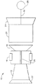
図1は、ガスタービンエンジン10の概略図であり、該ガスタービンエンジンは、直列に連結された、少なくとも1つの圧縮機12、燃焼器16、高圧タービン18、低圧タービン20、入口22、及び排気ノズル24を含む。1つの実施形態において、エンジン10は、オハイオ州シンシナチ所在のGeneral Electric Companyから商業的に入手可能なLM2500+型エンジンである。圧縮機12とタービン18とは第1のシャフト26によって連結され、タービン20と駆動負荷28とは第2のシャフト30によって連結されている。
【0007】
運転中、空気はエンジン入口22の中へ流れ、圧縮機12を通り、加圧される。次に、この加圧された空気は、燃焼器16に送り込まれ、そこで燃料と混合されて点火される。燃焼器16からの空気流は、回転タービン18及び20を駆動し、排気ノズル24を通ってガスタービンエンジン10から出ていく。
【0008】
図2は、エンジン10(図1に示す)に用いることができるフレームアウト検出装置50の概略図である。或いは、フレームアウト検出装置50は他の形式の発電装置に使用することもできる。フレームアウト検出装置50には、ガスジェネレータ速度52と、エンジン入口温度54と、ガスジェネレータ速度の変化率56とが入力される。図に示す通り、装置50は、ガスジェネレータ速度の変化率56(エンジンの減速度)に基づいて、また閾値予測60に基づいて、エンジンフレームアウト58が発生したと判定する。より具体的には、閾値予測60は、ガスジェネレータ速度52とエンジン入口温度54との関数として組み立てられている。ガスジェネレータ速度52と、エンジン入口温度54と、ガスジェネレータ速度の変化率56とは、本明細書では説明しない他の装置においてエンジン性能を監視する技術で使用される信号である。さらに、装置50は、これらの信号52、54、56をフレームアウト検出のために使用するので、エンジン10に追加のセンサを取り付ける必要はない。追加のセンサが不要であることは、センサを取り付けるためにエンジン構成部品を分解する必要がないので、エンジンの信頼性の維持及び向上を促進する。更に、装置50は追加のセンサが不要であるため、追加のセンサをガスタービンエンジン内に取り付けた時に発生しがちな、フレームアウト検出におけるエンジンごとのばらつきの低減が助長され、従って、誤ったフレームアウト表示を減少させ、又は排除することが容易になる。1つの実施形態において、時間遅延論理デバイス62が装置50に導入され、所定の閾値を満たしたと言ういかなる誤表示も低減することを可能にする。
【0009】
装置50における論理は、エンジンのテストデータに基づいた閾値予測スケジュールで実行される。この予測スケジュールは、急減速とそれに伴うフレームアウトの間に観測されるエンジン10の減速度テストデータに基づいている。他の実施形態においては、装置50は、エンジンの正常な減速時には機能しないように構成されている。
【0010】
フレームアウト検出に対する是正処置は、1つの実施形態では、エンジンに燃料を供給する燃料弁を閉じるようエンジン制御装置に信号を送ることを含む。別の実施形態においては、ガスタービンエンジン10は、オハイオ州シンシナチ所在のGeneral Electric Companyから商業的に入手可能なGE90型航空機エンジンであり、フレームアウト検出に対する是正処置は、エンジンを再点火する目的で、燃焼器の点火装置を作動させることを含む。エンジンのフレームアウトが表示されている時、エンジン10への燃料供給を遮断することにより、エンジン10の爆発的な再点火の可能性や、他の予期しない即ち不適切な事象が取り除かれる。1つの実施形態において、エンジンのフレームアウトが発生したかどうかを判断するために、閾値予測60に加えて減速度の閾値を利用する論理回路68に、燃料供給信号64と燃料レギュレータ信号66が入力される。
【0011】
上述のエンジンのフレームアウト検出装置は、費用効果が良くかつ信頼性がある。この装置は、エンジンの減速度を予め定められた閾値と比較し、その比較に基づいてフレームアウト状態を判断するための論理回路68を含む。予め定められた閾値は、1つの実施形態では、エンジン入口温度及びガスジェネレータ速度のうちの少なくとも1つに基づいている。別の実施形態では、フレームアウト検出は、燃料遮断弁に送られる信号を発生させ、燃料がエンジンに供給されるのを阻止し、その結果エンジンの爆発的な再点火を防ぐ。更に、上述の装置は、エンジン内に追加のセンサを使用したり、取り付けたりすることなく、エンジンのフレームアウトを検出する。その結果、追加のセンサによるエンジンの重量増加の恐れを減少、又は取り除くことが可能となる。更に、検出装置は既存のセンサを使用するので、この装置を完全なフレームアウト検出状態に維持するために何ら特別な較正やメンテナンスを必要とせず、又、他のエンジンのフレームアウト検出装置において存在が知られているエンジンごとのばらつきも減少、又は取り除くことが可能となる。結果として、フレームアウト検出装置は費用効果が良くかつ信頼性のある態様で、エンジンのフレームアウトの検出を助ける。
【0012】
本発明を、様々な特定の実施形態について説明してきたが、本発明が特許請求の範囲の技術思想及び技術的範囲内の変更で実施可能であることは当業者には明らかであろう。なお、特許請求の範囲に記載された符号は、理解容易のためであってなんら発明の技術的範囲を実施例に限縮するものではない。
【図面の簡単な説明】
【図1】 ガスタービンエンジンの概略図。
【図2】 フレームアウト検出装置の概略図。
【符号の説明】
50 フレームアウト検出装置
52 エンジンコア速度
54 エンジン入口温度
56 ガスジェネレータ速度の変化率
58 フレームアウト検出
60 閾値予測
62 時間遅延論理デバイス
64 燃料オン
66 レギュレータ
68 論理回路[0001]
BACKGROUND OF THE INVENTION
The present application relates generally to gas turbine engines, and more specifically to a flame out detection device for a gas turbine engine.
[0002]
BACKGROUND OF THE INVENTION
In turbojet, turbofan and gas turbine engine-based power generators, reliable detection of flameout in gas generators (a phenomenon in which combustion soot suddenly disappears and shuts down while the engine is running) is an appropriate follow-up to flameout It is important to perform various treatments on the catalyst. Depending on the engine type and engine application, an appropriate response action may initiate the engine reignition process. Alternatively, if it is determined that reignition is dangerous, an appropriate response action may shut off the fuel supply to the engine.
[0003]
At least some known frame-out detection devices include a sensor for detecting frame-out specifically in the engine. Such sensors are used in various flameout detection devices, including ultraviolet flame detectors, combustor pressure transducers, and fuel manifold pressure transducers. A plurality of frame-out detection sensors are combined with the engine for engine frame-out detection. This additional engine flameout detection sensor increases the overall cost and weight of the engine. In addition, due to the complexity of the engine, installing additional sensors adversely affects engine reliability. Furthermore, the use of additional sensors can cause engine-to-engine variability in frame-out detection, and this variability can cause erroneous display of frame-out in at least some known devices.
[0004]
SUMMARY OF THE INVENTION
In an exemplary embodiment, a flameout detection device for a gas turbine engine combustor enables engine flameout detection in a cost-effective and reliable manner. More specifically, the frame-out detection device detects engine frame-out without installing an additional engine sensor specific to engine frame-out detection. Rather, the flameout detection device uses existing sensor data, such as the rate of change of gas generator speed, to monitor engine flameout conditions.
[0005]
A method for detecting a flame out of a gas turbine engine using the apparatus includes a step of detecting a rate of change in gas generator speed and a step of determining that the engine is out of flame when an engine deceleration exceeds a predetermined threshold. Including. As a result, the frameout detection method using this frameout detection device is more cost effective and more reliable than other known frameout detection devices.
[Patent Document 1]
US Pat. No. 5,551,227 [0006]
DETAILED DESCRIPTION OF THE INVENTION
FIG. 1 is a schematic diagram of a
[0007]
During operation, air flows into
[0008]
FIG. 2 is a schematic diagram of a frame-out
[0009]
The logic in
[0010]
Corrective action for flameout detection, in one embodiment, includes signaling the engine controller to close the fuel valve that supplies fuel to the engine. In another embodiment,
[0011]
The engine flameout detection device described above is cost-effective and reliable. The apparatus includes a
[0012]
While the invention has been described in terms of various specific embodiments, those skilled in the art will recognize that the invention can be practiced with modification within the spirit and scope of the claims. In addition, the code | symbol described in the claim is for easy understanding, and does not limit the technical scope of an invention to an Example at all.
[Brief description of the drawings]
FIG. 1 is a schematic view of a gas turbine engine.
FIG. 2 is a schematic diagram of a frame-out detection device.
[Explanation of symbols]
50
Claims (9)
ガスジェネレータ速度(52)とエンジン入口温度(54)との関数として、エンジンの減速度の閾値を予め定める段階と、
検出されたガスジェネレータ速度の変化率(56)から、エンジンの減速度が前記閾値を超えたときにフレームアウトであると判定する段階と、
を含むことを特徴とする方法。A flameout detector (50) is used to add a gas turbine engine flameout (58) where the rate of change in gas generator speed (56) is detected to monitor engine performance . A method for detecting without providing a sensor ,
Predetermining an engine deceleration threshold as a function of gas generator speed (52) and engine inlet temperature (54);
From the rate of change of the sensed gas generator speed (56), the method determines that a flameout when deceleration of the engine exceeds the threshold value,
A method comprising the steps of:
ガスジェネレータ速度の変化信号で得られた比率(56)と、ガスジェネレータ速度(52)とエンジン入口温度(54)との関数として予め定められたエンジンの減速度の閾値とを比較するように構成され、ガスジェネレータ速度の変化率がエンジンの減速度を示す論理デバイス(62)と、
前記エンジンの減速度が前記予め定められた閾値を越えたときにエンジンフレームアウト(58)を表す信号を与えるように構成されている回路と、
を含むことを特徴とする装置(50)。Flameout detection device for a gas turbine engine (10) configured to detect a rate of change of gas generator speed (56) to monitor engine performance and without an additional sensor for flameout detection (50)
Comparing the ratio (56) obtained with the gas generator speed change signal to a predetermined engine deceleration threshold as a function of the gas generator speed (52) and the engine inlet temperature (54). A logic device (62) wherein the rate of change of gas generator speed indicates engine deceleration;
A circuit configured to provide a signal representative of engine flameout (58) when the engine deceleration exceeds the predetermined threshold;
A device (50) characterized by comprising:
Applications Claiming Priority (2)
| Application Number | Priority Date | Filing Date | Title |
|---|---|---|---|
| US09/859612 | 2001-05-17 | ||
| US09/859,612 US6442943B1 (en) | 2001-05-17 | 2001-05-17 | Methods and apparatus for detecting turbine engine flameout |
Publications (3)
| Publication Number | Publication Date |
|---|---|
| JP2003003864A JP2003003864A (en) | 2003-01-08 |
| JP2003003864A5 JP2003003864A5 (en) | 2005-08-25 |
| JP4113728B2 true JP4113728B2 (en) | 2008-07-09 |
Family
ID=25331330
Family Applications (1)
| Application Number | Title | Priority Date | Filing Date |
|---|---|---|---|
| JP2002142274A Expired - Fee Related JP4113728B2 (en) | 2001-05-17 | 2002-05-17 | Flame-out detection method, flame-out detection apparatus, and gas turbine engine |
Country Status (4)
| Country | Link |
|---|---|
| US (1) | US6442943B1 (en) |
| EP (1) | EP1258617B1 (en) |
| JP (1) | JP4113728B2 (en) |
| DE (1) | DE60239652D1 (en) |
Families Citing this family (14)
| Publication number | Priority date | Publication date | Assignee | Title |
|---|---|---|---|---|
| WO2003078813A1 (en) * | 2002-03-20 | 2003-09-25 | Ebara Corporation | Gas turbine apparatus |
| US7386982B2 (en) * | 2004-10-26 | 2008-06-17 | General Electric Company | Method and system for detecting ignition failure in a gas turbine engine |
| EP1953454A1 (en) * | 2007-01-30 | 2008-08-06 | Siemens Aktiengesellschaft | Method of detecting a partial flame failure in a gas turbine engine and a gas turbine engine |
| US7902999B2 (en) * | 2008-04-18 | 2011-03-08 | Honeywell International Inc. | Gas turbine engine rotor lock prevention system and method |
| US8151573B2 (en) * | 2008-11-06 | 2012-04-10 | Honeywell International Inc. | Turbomachine flameout confirmation |
| FR2951540B1 (en) * | 2009-10-19 | 2012-06-01 | Turbomeca | NON-EXTINGUISHING TEST FOR TURBOMACHINE COMBUSTION CHAMBER |
| US8457835B2 (en) | 2011-04-08 | 2013-06-04 | General Electric Company | System and method for use in evaluating an operation of a combustion machine |
| CN103089454B (en) * | 2013-02-04 | 2015-07-15 | 哈尔滨东安发动机(集团)有限公司 | Digital control apparatus of micro gas turbine |
| CN103114914B (en) * | 2013-02-04 | 2015-10-28 | 哈尔滨东安发动机(集团)有限公司 | The controlling method of miniature gas turbine |
| WO2015031318A1 (en) * | 2013-08-27 | 2015-03-05 | United Technologies Corporation | Gas turbine flameout detection |
| US10371002B2 (en) * | 2016-06-14 | 2019-08-06 | General Electric Company | Control system for a gas turbine engine |
| US11397135B2 (en) | 2017-03-14 | 2022-07-26 | General Electric Company | Method of detecting flameout in a combustor and turbine system |
| IT201700028052A1 (en) * | 2017-03-14 | 2018-09-14 | Nuovo Pignone Tecnologie Srl | METHOD TO DETECT THE EXTINCTION OF FLAME IN A BURNER AND A TURBINE SYSTEM |
| US20210396182A1 (en) * | 2020-06-23 | 2021-12-23 | Woodward, Inc. | Ignition system for power generation engine |
Family Cites Families (9)
| Publication number | Priority date | Publication date | Assignee | Title |
|---|---|---|---|---|
| GB1415681A (en) * | 1972-06-24 | 1975-11-26 | Rolls Royce | Flame-out control in gas turbine engine |
| US4044554A (en) | 1976-07-19 | 1977-08-30 | General Motors Corporation | Gas turbine engine fuel control |
| US4783957A (en) | 1986-12-23 | 1988-11-15 | Sundstrand Corporation | Fuel control circuit for a turbine engine |
| US5170621A (en) * | 1991-04-18 | 1992-12-15 | United Technologies Corporation | Flame failure detection |
| US5235802A (en) | 1991-04-18 | 1993-08-17 | United Technologies Corporation | Flame failure detection method |
| US5551227A (en) * | 1994-12-22 | 1996-09-03 | General Electric Company | System and method of detecting partial flame out in a gas turbine engine combustor |
| US5581995A (en) * | 1995-03-14 | 1996-12-10 | United Technologies Corporation | Method and apparatus for detecting burner blowout |
| US5828797A (en) | 1996-06-19 | 1998-10-27 | Meggitt Avionics, Inc. | Fiber optic linked flame sensor |
| US5961314A (en) | 1997-05-06 | 1999-10-05 | Rosemount Aerospace Inc. | Apparatus for detecting flame conditions in combustion systems |
-
2001
- 2001-05-17 US US09/859,612 patent/US6442943B1/en not_active Expired - Lifetime
-
2002
- 2002-05-15 DE DE60239652T patent/DE60239652D1/en not_active Expired - Lifetime
- 2002-05-15 EP EP02253387A patent/EP1258617B1/en not_active Expired - Lifetime
- 2002-05-17 JP JP2002142274A patent/JP4113728B2/en not_active Expired - Fee Related
Also Published As
| Publication number | Publication date |
|---|---|
| EP1258617A3 (en) | 2009-03-25 |
| EP1258617A2 (en) | 2002-11-20 |
| DE60239652D1 (en) | 2011-05-19 |
| EP1258617B1 (en) | 2011-04-06 |
| JP2003003864A (en) | 2003-01-08 |
| US6442943B1 (en) | 2002-09-03 |
Similar Documents
| Publication | Publication Date | Title |
|---|---|---|
| US5581995A (en) | Method and apparatus for detecting burner blowout | |
| JP4113728B2 (en) | Flame-out detection method, flame-out detection apparatus, and gas turbine engine | |
| JP4865276B2 (en) | Method and apparatus for avoiding lean blowout of a gas turbine engine | |
| CA2344210C (en) | Dynamic control system and method for catalytic combustion process and gas turbine engine utilizing same | |
| US7546741B2 (en) | Ignition detecting system and method for gas turbine | |
| EP2597258B1 (en) | Monitoring system and method of a turbine engine | |
| CA2608042C (en) | Method and device for regulating the operating line of a gas turbine combustion chamber | |
| JP5576676B2 (en) | Method for detecting flashback in a gas turbine engine | |
| US8342793B2 (en) | Active surge control | |
| JP5356949B2 (en) | Over-rotation prevention device for gas turbine engine | |
| US10371002B2 (en) | Control system for a gas turbine engine | |
| US20120088197A1 (en) | System and method for determining a flame condition in a combustor | |
| US20120006032A1 (en) | Systems, methods, and apparatus for confirming ignition in a gas turbine | |
| US20150075170A1 (en) | Method and system for augmenting the detection reliability of secondary flame detectors in a gas turbine | |
| US7930890B2 (en) | Method for protecting the hot gas parts of a gas turbine installation from overheating and for detecting flame extinction in the combustion chamber | |
| KR20210033518A (en) | Acoustic flashback detection in gas turbine combustion section | |
| JP2001033038A (en) | Flame detecting device for gas turbine | |
| JPH09287483A (en) | Gas turbine and misfire detecting method therefor | |
| KR19990063324A (en) | How to determine when the engine stall warning alarm is active | |
| JPH11148370A (en) | Gas turbine | |
| JPH0264231A (en) | Flame detecting method of gas turbine combustor | |
| Quentin et al. | Modified Fuel Control for a Large Heavy-Duty Combustion Turbine-Generator | |
| JPH03102118A (en) | Gas turbine combustor | |
| JPH08178272A (en) | Method for monitoring operating state of combustion device |
Legal Events
| Date | Code | Title | Description |
|---|---|---|---|
| A521 | Request for written amendment filed |
Free format text: JAPANESE INTERMEDIATE CODE: A523 Effective date: 20050210 |
|
| A621 | Written request for application examination |
Free format text: JAPANESE INTERMEDIATE CODE: A621 Effective date: 20050210 |
|
| A977 | Report on retrieval |
Free format text: JAPANESE INTERMEDIATE CODE: A971007 Effective date: 20070801 |
|
| A131 | Notification of reasons for refusal |
Free format text: JAPANESE INTERMEDIATE CODE: A131 Effective date: 20070807 |
|
| A601 | Written request for extension of time |
Free format text: JAPANESE INTERMEDIATE CODE: A601 Effective date: 20071106 |
|
| A602 | Written permission of extension of time |
Free format text: JAPANESE INTERMEDIATE CODE: A602 Effective date: 20071112 |
|
| A521 | Request for written amendment filed |
Free format text: JAPANESE INTERMEDIATE CODE: A523 Effective date: 20080205 |
|
| TRDD | Decision of grant or rejection written | ||
| A01 | Written decision to grant a patent or to grant a registration (utility model) |
Free format text: JAPANESE INTERMEDIATE CODE: A01 Effective date: 20080318 |
|
| A61 | First payment of annual fees (during grant procedure) |
Free format text: JAPANESE INTERMEDIATE CODE: A61 Effective date: 20080414 |
|
| R150 | Certificate of patent or registration of utility model |
Free format text: JAPANESE INTERMEDIATE CODE: R150 |
|
| FPAY | Renewal fee payment (event date is renewal date of database) |
Free format text: PAYMENT UNTIL: 20110418 Year of fee payment: 3 |
|
| FPAY | Renewal fee payment (event date is renewal date of database) |
Free format text: PAYMENT UNTIL: 20110418 Year of fee payment: 3 |
|
| FPAY | Renewal fee payment (event date is renewal date of database) |
Free format text: PAYMENT UNTIL: 20120418 Year of fee payment: 4 |
|
| FPAY | Renewal fee payment (event date is renewal date of database) |
Free format text: PAYMENT UNTIL: 20120418 Year of fee payment: 4 |
|
| FPAY | Renewal fee payment (event date is renewal date of database) |
Free format text: PAYMENT UNTIL: 20130418 Year of fee payment: 5 |
|
| FPAY | Renewal fee payment (event date is renewal date of database) |
Free format text: PAYMENT UNTIL: 20130418 Year of fee payment: 5 |
|
| FPAY | Renewal fee payment (event date is renewal date of database) |
Free format text: PAYMENT UNTIL: 20140418 Year of fee payment: 6 |
|
| R250 | Receipt of annual fees |
Free format text: JAPANESE INTERMEDIATE CODE: R250 |
|
| LAPS | Cancellation because of no payment of annual fees |