EP2597258B1 - Monitoring system and method of a turbine engine - Google Patents
Monitoring system and method of a turbine engine Download PDFInfo
- Publication number
- EP2597258B1 EP2597258B1 EP12193666.0A EP12193666A EP2597258B1 EP 2597258 B1 EP2597258 B1 EP 2597258B1 EP 12193666 A EP12193666 A EP 12193666A EP 2597258 B1 EP2597258 B1 EP 2597258B1
- Authority
- EP
- European Patent Office
- Prior art keywords
- bleed valve
- compressor
- compressor bleed
- operational value
- turbine engine
- Prior art date
- Legal status (The legal status is an assumption and is not a legal conclusion. Google has not performed a legal analysis and makes no representation as to the accuracy of the status listed.)
- Active
Links
- 238000012544 monitoring process Methods 0.000 title claims description 54
- 238000000034 method Methods 0.000 title claims description 31
- 238000010200 validation analysis Methods 0.000 claims description 8
- 238000004891 communication Methods 0.000 claims description 5
- 238000010248 power generation Methods 0.000 description 9
- 239000000446 fuel Substances 0.000 description 6
- 239000007789 gas Substances 0.000 description 6
- 239000000567 combustion gas Substances 0.000 description 5
- 238000011144 upstream manufacturing Methods 0.000 description 4
- 230000001133 acceleration Effects 0.000 description 3
- 230000006870 function Effects 0.000 description 3
- 239000000203 mixture Substances 0.000 description 3
- 238000002485 combustion reaction Methods 0.000 description 2
- 238000010586 diagram Methods 0.000 description 2
- 238000007689 inspection Methods 0.000 description 2
- VNWKTOKETHGBQD-UHFFFAOYSA-N methane Chemical compound C VNWKTOKETHGBQD-UHFFFAOYSA-N 0.000 description 2
- 238000003491 array Methods 0.000 description 1
- 239000004020 conductor Substances 0.000 description 1
- 230000007423 decrease Effects 0.000 description 1
- 230000000694 effects Effects 0.000 description 1
- 239000000284 extract Substances 0.000 description 1
- -1 for example Substances 0.000 description 1
- 239000000295 fuel oil Substances 0.000 description 1
- 239000004973 liquid crystal related substance Substances 0.000 description 1
- 239000003345 natural gas Substances 0.000 description 1
- 230000007935 neutral effect Effects 0.000 description 1
- 230000000704 physical effect Effects 0.000 description 1
- 230000004044 response Effects 0.000 description 1
- 239000007787 solid Substances 0.000 description 1
- 230000007704 transition Effects 0.000 description 1
- 230000000007 visual effect Effects 0.000 description 1
Images

Classifications
-
- F—MECHANICAL ENGINEERING; LIGHTING; HEATING; WEAPONS; BLASTING
- F01—MACHINES OR ENGINES IN GENERAL; ENGINE PLANTS IN GENERAL; STEAM ENGINES
- F01D—NON-POSITIVE DISPLACEMENT MACHINES OR ENGINES, e.g. STEAM TURBINES
- F01D5/00—Blades; Blade-carrying members; Heating, heat-insulating, cooling or antivibration means on the blades or the members
- F01D5/12—Blades
- F01D5/14—Form or construction
- F01D5/141—Shape, i.e. outer, aerodynamic form
-
- F—MECHANICAL ENGINEERING; LIGHTING; HEATING; WEAPONS; BLASTING
- F02—COMBUSTION ENGINES; HOT-GAS OR COMBUSTION-PRODUCT ENGINE PLANTS
- F02C—GAS-TURBINE PLANTS; AIR INTAKES FOR JET-PROPULSION PLANTS; CONTROLLING FUEL SUPPLY IN AIR-BREATHING JET-PROPULSION PLANTS
- F02C9/00—Controlling gas-turbine plants; Controlling fuel supply in air- breathing jet-propulsion plants
- F02C9/16—Control of working fluid flow
- F02C9/18—Control of working fluid flow by bleeding, bypassing or acting on variable working fluid interconnections between turbines or compressors or their stages
-
- F—MECHANICAL ENGINEERING; LIGHTING; HEATING; WEAPONS; BLASTING
- F02—COMBUSTION ENGINES; HOT-GAS OR COMBUSTION-PRODUCT ENGINE PLANTS
- F02C—GAS-TURBINE PLANTS; AIR INTAKES FOR JET-PROPULSION PLANTS; CONTROLLING FUEL SUPPLY IN AIR-BREATHING JET-PROPULSION PLANTS
- F02C9/00—Controlling gas-turbine plants; Controlling fuel supply in air- breathing jet-propulsion plants
- F02C9/48—Control of fuel supply conjointly with another control of the plant
- F02C9/50—Control of fuel supply conjointly with another control of the plant with control of working fluid flow
- F02C9/52—Control of fuel supply conjointly with another control of the plant with control of working fluid flow by bleeding or by-passing the working fluid
-
- F—MECHANICAL ENGINEERING; LIGHTING; HEATING; WEAPONS; BLASTING
- F02—COMBUSTION ENGINES; HOT-GAS OR COMBUSTION-PRODUCT ENGINE PLANTS
- F02C—GAS-TURBINE PLANTS; AIR INTAKES FOR JET-PROPULSION PLANTS; CONTROLLING FUEL SUPPLY IN AIR-BREATHING JET-PROPULSION PLANTS
- F02C9/00—Controlling gas-turbine plants; Controlling fuel supply in air- breathing jet-propulsion plants
- F02C9/26—Control of fuel supply
- F02C9/28—Regulating systems responsive to plant or ambient parameters, e.g. temperature, pressure, rotor speed
-
- F—MECHANICAL ENGINEERING; LIGHTING; HEATING; WEAPONS; BLASTING
- F05—INDEXING SCHEMES RELATING TO ENGINES OR PUMPS IN VARIOUS SUBCLASSES OF CLASSES F01-F04
- F05D—INDEXING SCHEME FOR ASPECTS RELATING TO NON-POSITIVE-DISPLACEMENT MACHINES OR ENGINES, GAS-TURBINES OR JET-PROPULSION PLANTS
- F05D2240/00—Components
- F05D2240/10—Stators
- F05D2240/12—Fluid guiding means, e.g. vanes
- F05D2240/127—Vortex generators, turbulators, or the like, for mixing
-
- F—MECHANICAL ENGINEERING; LIGHTING; HEATING; WEAPONS; BLASTING
- F05—INDEXING SCHEMES RELATING TO ENGINES OR PUMPS IN VARIOUS SUBCLASSES OF CLASSES F01-F04
- F05D—INDEXING SCHEME FOR ASPECTS RELATING TO NON-POSITIVE-DISPLACEMENT MACHINES OR ENGINES, GAS-TURBINES OR JET-PROPULSION PLANTS
- F05D2260/00—Function
- F05D2260/80—Diagnostics
-
- F—MECHANICAL ENGINEERING; LIGHTING; HEATING; WEAPONS; BLASTING
- F05—INDEXING SCHEMES RELATING TO ENGINES OR PUMPS IN VARIOUS SUBCLASSES OF CLASSES F01-F04
- F05D—INDEXING SCHEME FOR ASPECTS RELATING TO NON-POSITIVE-DISPLACEMENT MACHINES OR ENGINES, GAS-TURBINES OR JET-PROPULSION PLANTS
- F05D2270/00—Control
- F05D2270/40—Type of control system
- F05D2270/44—Type of control system active, predictive, or anticipative
-
- Y—GENERAL TAGGING OF NEW TECHNOLOGICAL DEVELOPMENTS; GENERAL TAGGING OF CROSS-SECTIONAL TECHNOLOGIES SPANNING OVER SEVERAL SECTIONS OF THE IPC; TECHNICAL SUBJECTS COVERED BY FORMER USPC CROSS-REFERENCE ART COLLECTIONS [XRACs] AND DIGESTS
- Y02—TECHNOLOGIES OR APPLICATIONS FOR MITIGATION OR ADAPTATION AGAINST CLIMATE CHANGE
- Y02T—CLIMATE CHANGE MITIGATION TECHNOLOGIES RELATED TO TRANSPORTATION
- Y02T50/00—Aeronautics or air transport
- Y02T50/60—Efficient propulsion technologies, e.g. for aircraft
Definitions
- the subject matter described herein relates generally to turbine engines and, more particularly, to systems and methods for use in monitoring the operation of turbine engines.
- At least some known gas turbine engines include a compressor, a combustor coupled downstream from the compressor, a turbine, and a rotor assembly rotatably coupled between the compressor and the turbine.
- the compressor compresses air, which is mixed with fuel and channeled to the combustor. The mixture is ignited generating hot combustion gases that are channeled to the turbine.
- the turbine extracts energy from the combustion gases for powering the compressor, as well as producing useful work to power a load, such as an electrical generator, or to propel an aircraft in flight.
- compressor bleed valves regulate air flow through the compressor.
- US 4,756,152 A discloses a control system that modulates the compressor bleed valve between full open and full closed positions during engine deceleration as a function of the ratio of the actual rate of speed change (e.g. deceleration) of the compressor to a maximum scheduled rate of speed change of the compressor. The closer the actual is to the maximum, the more the bleed valves are opened and biased by corrected compressor rotor speed. The continuous modulation of the bleed valve during engine transients provides smooth thrust transition from one steady state condition to another.
- US 4,603,546 A relates to a control system in gas turbine aeroengines, which permits operation of a damaged engine without substantial danger from surge and which at the same time will continue to provide good fuel economy. Achieving this through reliably detecting compressor surge by continuously monitoring the pressure at the outlet of the compressor; detecting the onset of compressor surge i.e. when the ratio of the first derivative in time of the monitored pressure to the monitored pressure itself is less than a predetermined value and then restore normal operation without intervention from the pilot by opening the bleed valves and preferably by actuating a fuel dip unit in order temporarily but greatly to reduce the fuel flow rate by withdrawing fuel from the supply line.
- US 5,857,321 A deals with a controller with neutral network for estimating gas turbine internal cycle parameters for which the turbine has no corresponding operating parameter sensor rapidly and accurately over a wide range of turbine performance.
- a monitoring system for use with a turbine engine includes a compressor and at least one compressor bleed valve coupled to the compressor.
- the monitoring system includes at least one sensor for sensing an operational parameter of the compressor bleed valve, and a controller that is coupled to the sensor and the compressor bleed valve.
- the controller is configured to determine an operating mode of the turbine engine via a turbine operation module of the controller and receive a monitoring signal indicative of the sensed operational parameter via the turbine operation module and/or a valve performance module of the controller.
- the controller is also configured to calculate at least one operational value of the compressor bleed valve based at least in part on the sensed operational parameter, wherein the calculated operational value is associated with the determined operating mode via the performance module of the controller.
- the controller is further configured to determine a condition of the turbine engine based at least in part on the calculated compressor bleed valve operational value via a predictive operation module of the controller.
- a turbine engine in another aspect, includes a compressor, a turbine coupled in flow communication with the compressor to receive at least some of the air discharged by said compressor, at least one compressor bleed valve coupled to the compressor, and a monitoring system operatively coupled to the compressor bleed valve and to the compressor.
- a method of monitoring a turbine engine includes a compressor and a compressor bleed valve that is coupled to the compressor.
- the method includes determining, by a controller, an operating mode of the turbine engine.
- At least one monitoring signal indicative of an operating parameter of the compressor bleed valve is transmitted from a sensor to the controller.
- At least one operational value of the compressor bleed valve is calculated based at least in part on the received monitoring signal, wherein the calculated operational value is associated with the determined operating mode.
- a condition of the turbine engine is determined based at least in part on the calculated compressor bleed valve operational value.
- the method further comprises the steps of transmitting, from the controller to the compressor bleed valve, a command signal indicative of a command to operate; transmitting, from the compressor bleed valve to the controller, a validation signal indicative of a completed operation; calculating a slew rate indicative of a period of time between commanding the compressor bleed valve to operate and validating an operation of the compressor bleed valve; and calculating the compressor bleed valve operational value based at least in part on the calculated compressor bleed valve slew rate.
- the exemplary methods and systems described herein overcome at least some disadvantages of known turbine engine systems by providing a monitoring system that can enable a condition of a compressor bleed valve to be determined while the turbine engine system remains online.
- the embodiments described herein include a condition monitoring system that determines a compressor bleed valve condition based on a sensed operating parameter of the compressor bleed valve, wherein the sensed operating parameter is associated with an operating mode of the turbine engine.
- the condition monitoring system facilitates preventing conditions such as turbine engine trip that may cause damage to the turbine engine system.
- the cost of operating the turbine engine system is reduced.
- upstream refers to a forward end of a turbine engine
- downstream refers to an aft end of a turbine engine
- FIG. 1 is a schematic view of an exemplary turbine engine 10.
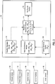
- FIG. 2 is a block diagram of an exemplary monitoring system 12 that may be used with turbine engine 10.
- turbine engine 10 includes an intake section 14, a compressor section 16 downstream from intake section 14, a combustor section 18 downstream from compressor section 16, a turbine section 20 downstream from combustor section 18, and an exhaust section 22.
- Combustor section 18 includes a plurality of combustors 24.
- Combustor section 18 is coupled to compressor section 16 such that each combustor 24 is in flow communication with compressor section 16.
- a rotor assembly 26 is coupled to turbine section 20 and compressor section 16.
- Rotor assembly 26 includes a drive shaft 28 that extends between turbine section 20 and compressor section 16.
- Turbine section 20 is rotatably coupled to compressor section 16 and to an electrical generator 30 with drive shaft 28 to impart a power loading to generator 30 during operation of turbine engine 10.
- Generator 30 is coupled to a power source, such as for example, an electric utility grid (not shown) for distributing electrical power to the utility grid.
- compressor section 16 includes a compressor 32 that includes a plurality of stages 34 that extend between an upstream section 36 and a downstream section 38 along a centerline axis 40. Each stage 34 is configured to channel air towards an adjacent stage 34 from upstream section 36 towards downstream section 38 such that compressed air is discharged from downstream section 38 into combustor section 18.
- compressor section 16 includes at least one compressor bleed valve 42 that is coupled to compressor 32. Compressor bleed valve 42 is moved between an open position (not shown), and a closed position (not shown). In the open position, compressor bleed valve 42 enables at least a portion of air being channeled through compressor 32 to be channeled from upstream section 36 to downstream section 38 to bypass one or more stages 34.
- compressor bleed valve 42 in the open position, compressor bleed valve 42 enables a portion of air to bypass one or more stages 34 to adjust a pressure of air channeled through compressor 32 and/or adjust a temperature of compressed air discharged from compressor 32. In the closed position, compressor bleed valve 42 prevents air from bypassing stages 34.
- Combustor section 18 injects fuel, for example, natural gas and/or fuel oil, into the air flow, ignites the fuel-air mixture to expand the fuel-air mixture through combustion, and generates high temperature combustion gases. Combustion gases are discharged from combustor section 18 towards turbine section 20 wherein thermal energy in the gases is converted to mechanical rotational energy. Combustion gases impart rotational energy to turbine section 20 and to rotor assembly 26, which subsequently provides rotational power to compressor section 16.
- fuel for example, natural gas and/or fuel oil
- turbine engine 10 is operated through a plurality of operating cycles, wherein each operating cycle includes a plurality of operational modes.
- turbine engine 10 is selectively operable in a first or start-up mode, a second or power generation mode, and/or a third or shutdown mode.
- start-up mode refers to a mode of operation in which a rotational speed of rotor assembly 26 is increased at a predefined rate of acceleration until rotor assembly 26 is rotated at a predefined speed with no electrical power load imparted to generator 30.
- the term "power generation mode” refers to a mode of operation in which an electrical power load is imparted to generator 30 with rotor assembly 26 at the predefined speed such that turbine engine 10 is operated to generate a predefined power output of generator 30.
- the term “shutdown mode” refers to a mode of operation in which turbine engine 10 is moved offline wherein no power load is imparted to generator 30 and rotor assembly speed is reduced at a predefined rate of deceleration.
- turbine engine 10 may be selectively changed between start-up mode, power generation mode, and shutdown mode.
- compressor bleed valves 42 are repositioned to the open position to enable a portion of air being channeled through compressor section 16 to bypass compressor stages 34 to facilitate reducing a compressor surge during gas turbine start-up. If compressor bleed valve 42 is in a closed position during start-up mode, compressor 32 may generate a compressed air surge through compressor 32, which may generate undesired vibrations within compressor 32 and/or stall compressor 32. Moreover, if compressor bleed valve 42 fails to open within predefined period of time during start-up mode, turbine engine 10 may trip and move offline.
- compressor bleed valves 42 are repositioned to the closed position to prevent air from bypassing compressor stages 34. If compressor bleed valve 42 is repositioned to the open position during power generation mode, compressor 32 may generate pressure fluctuations within compressed air being discharged towards combustor 24, and cause undesired combustion instability. In addition, if compressor bleed valve 42 opens during power generation mode, turbine engine 10 may trip and/or move to shutdown mode. During shutdown mode, compressor bleed valve 42 is repositioned to the open position to reduce a pressure differential across compressor 32 to facilitate reducing a rotational speed of rotor assembly 26. If compressor bleed valve 42 is repositioned to the closed position and/or fails to move to the open position during shutdown mode, compressor 32 may generate compressed air surge through compressor 32 and cause a turbine engine 10 to trip.
- monitoring system 12 is coupled to turbine engine 10 for monitoring an operation of turbine engine 10. Moreover, monitoring system 12 is configured to monitor a condition of compressor bleed valve 42 to facilitate determining whether compressor bleed valve 42 may fail during operation of turbine engine 10, and cause a trip of turbine engine 10. More specifically, monitoring system 12 is also configured to determine an operating mode of turbine engine 10, calculate an operational value of compressor bleed valve 42 associated with the determined operating mode, and determine a condition of turbine engine 10 based at least in part on the calculated compressor bleed valve operational value. In addition, monitoring system 12 is configured to determine a condition of turbine engine 10 to be less than a predefined condition upon determining the calculated compressor bleed valve operational value is different from a predefined operational value. Moreover, monitoring system 12 is configured to transmit a notification signal to a user upon determining that the condition of turbine engine 10 is less than the predefined condition.
- monitoring system 12 includes a controller 44 that is coupled in communication with a plurality of sensors 46.
- Each sensor 46 detects various parameters relative to the operation of turbine engine 10, and the operation and position of compressor bleed valve 42.
- Sensors 46 may include, but are not limited to only including, position sensors, vibration sensors, acceleration sensors, temperature sensors, pressure sensors, and/or any other sensors that sense various parameters relative to the operation of turbine engine 10, and the operation and position of compressor bleed valve 42.
- the term "parameters” refers to physical properties whose values can be used to define the operational mode, orientation, position, and operating conditions of turbine engine 10 and/or compressor bleed valve 42, such as operating mode, compressor discharge temperature, compressor discharge pressure, compressor bleed valve operating position, rotational speed, vibrations and accelerations at defined locations.
- Monitoring system 12 includes a first sensor 48, i.e. an proximity sensor, that is coupled to rotor assembly 26 for sensing a rotational speed of drive shaft 28 and that transmits a signal indicative of the sensed speed to controller 44.
- a second sensor 50 i.e. a pressure sensor, is coupled to compressor 32 for sensing a pressure of compressed air discharged from compressor 32, and transmits a signal indicative of the sensed compressor discharge pressure to controller 44.
- a third sensor 52 i.e. a temperature sensor, is coupled to compressor 32 for sensing a temperature of compressed air discharged from compressor 32, and that transmits a signal indicative of the sensed compressor discharge temperature to controller 44.
- monitoring system 12 includes a fourth sensor 54, i.e. a position sensor, that is coupled to compressor bleed valve 42 for sensing an operating position of compressor bleed valve 42, and that transmits a signal indicative of the sensed valve operating position to controller 44.
- controller 44 includes a processor 56 and a memory device 58.
- Processor 56 includes any suitable programmable circuit which may include one or more systems and microcontrollers, microprocessors, reduced instruction set circuits (RISC), application specific integrated circuits (ASIC), programmable logic circuits (PLC), field programmable gate arrays (FPGA), and any other circuit capable of executing the functions described herein.
- RISC reduced instruction set circuits
- ASIC application specific integrated circuits
- PLC programmable logic circuits
- FPGA field programmable gate arrays
- Memory device 58 includes a computer readable medium, such as, without limitation, random access memory (RAM), flash memory, a hard disk drive, a solid state drive, a diskette, a flash drive, a compact disc, a digital video disc, and/or any suitable device that enables processor 56 to store, retrieve, and/or execute instructions and/or data.
- RAM random access memory
- flash memory such as, without limitation, a hard disk drive, a solid state drive, a diskette, a flash drive, a compact disc, a digital video disc, and/or any suitable device that enables processor 56 to store, retrieve, and/or execute instructions and/or data.
- controller 44 includes a control interface 60 that is coupled to compressor bleed valve 42 to control an operation of compressor bleed valve 42.
- controller 44 also includes a sensor interface 62 that is coupled to at least one sensor 46 such as, for example, first, second, third, and fourth sensors 48, 50, 52, and 54.
- Each sensor 46 may transmit a signal continuously, periodically, or only once and/or any other signal timing that enables monitoring system 12 to function as described herein.
- each sensor 46 may transmit a signal either in an analog form or in a digital form.
- Controller 44 also includes a display 64 and a user interface 66.
- Display 64 includes a vacuum fluorescent display (VFD) and/or one or more light-emitting diodes (LED). Additionally or alternatively, display 64 may include, without limitation, a liquid crystal display (LCD), a cathode ray tube (CRT), a plasma display, and/or any suitable visual output device capable of displaying graphical data and/or text to a user.
- a turbine engine operating mode, a compressor bleed valve position, a turbine engine condition, a compressor bleed valve condition, and/or any other information may be displayed to a user on display 64.
- User interface 66 includes, without limitation, a keyboard, a keypad, a touch-sensitive screen, a scroll wheel, a pointing device, an audio input device employing speech-recognition software, and/or any suitable device that enables a user to input data into controller 44 and/or to retrieve data from controller 44.
- user interface 66 is integrated with display 64 such that user interface 66 is accessed by a user via display 64.
- user may input control parameters into controller 44 using user interface 66 to control an operation of turbine engine 10 and/or compressor bleed valve 42.
- connections are available between control interface 60 and compressor bleed valve 42, between sensor interface 62 and sensors 46, and between processor 56, memory device 58, display 64, and user interface 66.
- Such connections may include, without limitation, an electrical conductor, a low-level serial data connection, such as Recommended Standard (RS) 232 or RS-485, a high-level serial data connection, such as Universal Serial Bus (USB) or Institute of Electrical and Electronics Engineers (IEEE) 1394 (a/k/a FIREWIRE), a parallel data connection, such as IEEE 1284 or IEEE 488, a short-range wireless communication channel such as BLUETOOTH, and/or a private (e.g., inaccessible outside turbine engine 10) network connection, whether wired or wireless.
- RS Recommended Standard
- IEEE Institute of Electrical and Electronics Engineers 1394
- a parallel data connection such as IEEE 1284 or IEEE 488
- a short-range wireless communication channel such as BLUETOOTH
- a private e.g., inaccessible outside turbine
- controller 44 receives a signal indicative of an operating parameter of turbine engine 10 from sensor 46, and determines an operating mode of turbine engine 10 based at least in part on the sensed turbine operating parameter. In addition, controller 44 receives a signal indicative of a sensed operational parameter of compressor bleed valve 42 from sensor 46, wherein the sensed operational parameter is associated with the determined turbine operating mode. Controller 44 calculates at least one operational value of compressor bleed valve 42 based at least in part on the sensed compressor bleed valve operational parameter, and determines a condition of turbine engine 10 based at least in part on the calculated compressor bleed valve operational value.
- controller 44 determines a condition of turbine engine 10 to be less than a predefined turbine engine condition upon determining the calculated compressor bleed valve operational value to be different than a predefined compressor bleed valve operational value.
- controller 44 calculates a baseline operational value based at least in part on a plurality of calculated operational values that are associated with a plurality of turbine operating cycles.
- controller 44 calculates a baseline operational value that is indicative of a normal operation of compressor bleed valve 42, wherein compressor bleed valve 42 operates without a failure, and turbine engine 10 operates within a predefined range of operating parameters.
- Controller 44 also determines a condition of turbine engine 10 to be less than a predefined turbine engine condition upon determining that the calculated compressor bleed valve operational value is different from the calculated baseline operational value.
- controller 44 includes a turbine operation module 68, a valve performance module 70, a baseline operation module 72, a predictive operation module 74, and a notification module 76.
- Turbine operation module 68 is configured to receive from sensor 46 signals indicative of operating parameters of turbine engine 10, and determine an operating mode of turbine engine 10 based at least in part on the received signals.
- turbine operation module 68 receives a signal indicative of a rotational speed of drive shaft 28 from proximity sensor 48, and calculates an operational mode (TE o ) of turbine engine 10 based at least in part on the sensed rotational speed.
- Turbine operation module 68 transmits a signal indicative of the determined operation mode (TE o ) to valve performance module 70, baseline operation module 72, and predictive operation module 74.
- Valve performance module 70 calculates a plurality of operational values (CBV) indicative of a condition of compressor bleed valve 42 associated with operational mode (TE o ). More specifically, sensor 46 transmits at least one monitoring signal indicative of an operating parameter of compressor bleed valve 42 to valve performance module 70. Valve performance module 70 calculates at least one compressor bleed valve operational value (CBV) associated with operational mode (TE o ) and transmits a signal indicative of the calculated operational value (CBV) to predictive operation module 74 and baseline operation module 72.
- CBV compressor bleed valve operational value
- Predictive operation module 74 determines a condition of turbine engine 10 based at least in part on the calculated operational value (CBV). More specifically, predictive operation module 74 determines a condition of turbine engine 10 to be less than a predefined turbine engine condition upon determining the calculated operational value (CBV) to be different than a predefined operational value (CBV p ).
- Baseline operation module 72 receives a plurality of calculated operational values (CBV) from valve performance module 70 associated with a plurality of turbine engine operating cycles, wherein each calculated operational value (CBV) is associated with a calculated turbine engine operational mode (TE o ).
- Baseline operation module 72 calculates a baseline operational value (CBV b ) based at least in part on the plurality of calculated operational values (CBV), and transmits a signal indicative of the calculated baseline operational value (CBV b ) to predictive operation module 74.
- predictive operation module 74 determines a condition of turbine engine 10 to be less than a predefined turbine engine condition upon determining the calculated operational value (CBV) to be different than the calculated baseline operational value (CBV b ).
- predictive operation module 74 determines a condition of compressor bleed valve 42 to be indicative of a failure of compressor bleed valve 42 upon determining the calculated operational value (CBV) to be different than the calculated baseline operational value (CBV b ).
- Notification module 76 transmits a first notification signal indicative of a first alarm to display 64 after predictive operation module 74 determines a condition of turbine engine 10 to be less than a predefined turbine engine condition. Moreover, notification module 76 transmits a second notification signal indicative of a second alarm to display 64 after prediction module determines a condition of compressor bleed valve 42 to be a failure of compressor bleed valve 42.
- valve performance module 70 receives a first signal indicative of a sensed compressor discharge temperature from temperature sensor 52, and calculates a first operational value (CBV 1 ) based at least in part on the sensed compressor discharge temperature.
- first operational value (CBV 1 ) represents a change in compressor discharge temperature over time.
- baseline operation module 72 calculates a first baseline operational value (CBV b1 ) based at least in part on a plurality of first operational values (CBV 1 ).
- Predictive operation module 74 determines a condition of turbine engine 10 to be less than a predefined turbine engine condition upon determining the calculated first operational value (CBV 1 ) to be different than the calculated first baseline operational value (CBV b1 ).
- baseline operation module 72 calculates first baseline operational value (CBV b1 ) including a normal distribution including mean and standard deviation of compressor discharge temperatures during start-up mode and shutdown mode.
- Valve performance module 70 calculates first operational value (CBV 1 ) including a z-score based at least in part on the calculated normal distribution.
- Predictive operation module 74 determines a condition of turbine engine 10 to be less than a predefined turbine engine condition upon determining the calculated first operational value (CBV 1 ) including the calculated compressor discharge temperature z-score to be different than a predefined z-score.
- Valve performance module 70 also receives a signal indicative of a sensed compressor discharge pressure from pressure sensor 50, and calculates a second operational value (CBV 2 ) based at least in part on the sensed compressor discharge pressure.
- Baseline operation module 72 calculates a second baseline operational value (CBV b2 ) based at least in part on a plurality of second operational values (CBV 2 ).
- Predictive operation module 74 determines a condition of turbine engine 10 to be less than a predefined turbine engine condition upon determining the calculated second operational value (CBV 2 ) to be different than the calculated second baseline operational value (CBV b2 ).
- valve performance module 70 calculates second operational value (CBV 2 ) including a pressure decay rate of compressor 32 during shutdown mode based at least in part on the sensed compressor discharge pressure.
- the calculated pressure decay rate includes a rate at which the sensed compressor discharge pressure decreases during a predefined period of time during shutdown mode.
- Predictive operation module 74 determines a condition of turbine engine 10 to be less than a predefined turbine engine condition upon determining the calculated second operational value (CBV 2 ) including the calculated pressure decay rate to be different than a predefined compressor discharge pressure decay rate.
- valve performance module 70 calculates second operational value (CBV 2 ) including a pressure rise rate of compressor 32 during start-up mode.
- the calculated pressure rise rate includes a rate at which the sensed compressor discharge pressure increases during a predefined period of time during start-up mode.
- Predictive operation module 74 determines a condition of turbine engine 10 to be less than a predefined turbine engine condition upon determining the calculated second operational value (CBV 2 ) including the calculated pressure rise rate to be different than a predefined compressor discharge pressure rise rate.
- controller 44 transmits a plurality of command signals to compressor bleed valve 42 to reposition compressor bleed valve 42.
- the plurality of command signals are transmitted consecutively from controller 44 to compressor bleed valve 42.
- Position sensor 54 transmits a validation signal indicative of a position of compressor bleed valve 42.
- Valve performance module 70 calculates a slew rate indicative of a period of time between a time an initial command signal is transmitted to compressor bleed valve 42 and the validation signal is transmitted to valve performance module 70 indicating the compressor bleed valve 42 is repositioned in response to the command signal.
- performance module calculates a third operational value (CBV 3 ) based at least in part on the calculated slew rate.
- baseline operation module 72 calculates a third baseline operational value (CBV b3 ) based at least in part on a plurality of third operational values (CBV 3 ).
- Predictive operation module 74 determines a condition of turbine engine 10 to be less than a predefined turbine engine condition upon determining the calculated third operational value (CBV 3 ) to be different than the calculated third baseline operational value (CBV b3 ).
- valve performance module 70 also calculates an amount of occurrences a command signal is transmitted to compressor bleed valve 42 before receiving a validation signal from position sensor 54.
- Valve performance module 70 calculates a fourth operational value (CBV 4 ) based at least in part on the calculated amount of command signals transmitted to compressor bleed valve 42.
- baseline operation module 72 calculates a fourth baseline operational value (CBV b4 ) based at least in part on a plurality of fourth operational values (CBV 4 ).
- Predictive operation module 74 determines a condition of turbine engine 10 to be less than a predefined turbine engine condition upon determining the calculated fourth operational value (CBV 4 ) to be different than the calculated fourth baseline operational value (CBVb4).
- predictive operation module 74 calculates an operational value error (e) based at least in part on the difference between the calculated operational value (CBV) and the calculated baseline operation valve (CBV b ). In addition, predictive operation module 74 calculates a first operational value error (e 1 ) between first operational value (CBV 1 ) and first baseline operational value (CBV b1 ), calculates a second operational value error (e 2 ) between second operational value (CBV 2 ) and second baseline operational value (CBV b2 ), calculates a third operational value error (e 3 ) between third operational value (CBV 3 ) and third baseline operational value (CBV b3 ), and/or calculates a fourth operational value error (e 4 ) between fourth operational value (CBV 4 ) and fourth baseline operational value (CBV b4 ).
- predictive operation module 74 applies one or more weighting factors ( ⁇ , ⁇ , ⁇ , ⁇ and n-factor) to each first operational value error (e 1 ), second operational value error (e 2 ), third operational value error (e 3 ), and fourth operational value error (e 4 ) to calculate a collective operational error value (ec).
- Predictive operation module 74 determines a condition of turbine engine 10 to be less than a predefined turbine engine condition upon determining the collective operational value error (e c ) to be different than a predefined operational value error.
- predictive operation module 74 applies one or more weighting factors ( ⁇ , ⁇ , ⁇ , ⁇ and n-factor) to each first operational value (CBV 1 ), second operational value (CBV 2 ), third operational value (CBV 3 ), and fourth operational value (CBV 4 ) to calculate a collective operational value (CBVc).
- predictive operation module 74 also applies one or more weighting factors ( ⁇ , ⁇ , ⁇ , ⁇ and n-factor) to each first baseline operational value (CBV b4 ), second baseline operational value (CBV b4 ), third baseline operational value (CBV b4 ), and fourth baseline operational value (CBV b4 ) to calculate a collective operational value (CBV bc ).
- predictive operation module 74 determines a condition of turbine engine 10 to be less than a predefined turbine engine condition upon determining the collective operational value (CBV c ) to be different than the calculated collective baseline operational value (CBVbc).
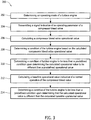
- FIG. 3 is a flow chart of an exemplary method that may be used to monitor turbine engine 10.
- Method 200 includes determining 202, by controller 44, an operating mode of turbine engine 10, and transmitting 204 at least one monitoring signal indicative of an operating parameter of compressor bleed valve 42 from sensor 46 to controller 44.
- Method 200 also includes calculating 206 at least one operational value (CBV) based at least in part on the received monitoring signal, and determining 208 a condition of turbine engine 10 based at least in part on the calculated compressor bleed valve operational value (CBV).
- method 200 includes determining 210 a condition of turbine engine 10 to be less than a predefined condition upon determining the calculated compressor bleed valve operational value (CBV) to be different than a predefined compressor bleed valve operational value (CBV p ).
- method 200 includes calculating 212 a baseline operational value (CBV b ) that is indicative of a normal operation of compressor bleed valve 42 based at least in part on the monitoring signal, and determining 214 a condition of the turbine engine to be less than a predefined condition upon determining that the calculated compressor bleed valve operational value is different than the calculated baseline operational value.
- CBV b baseline operational value
- method 200 includes transmitting a monitoring signal indicative of a discharge temperature of compressor 32, and calculating a first operational value (CBV 1 ) based at least in part on the sensed compressor discharge temperature.
- Method 200 also includes transmitting a monitoring signal indicative of a discharge pressure of compressor 32, and calculating a second operational value (CBV 2 ) based at least in part on the sensed compressor discharge pressure.
- method 200 includes transmitting a command signal indicative of a command to operate compressor bleed valve 42, from controller 44 to compressor bleed valve 42, and transmitting a validation signal indicative of a completed operation.
- method 200 includes calculating a slew rate indicative of a period of time between commanding compressor bleed valve 42 to operate, and validating an operation of compressor bleed valve 42.
- a third compressor bleed valve operational value (CBV 3 ) is calculated based at least in part on the calculated compressor bleed valve slew rate.
- Method 200 also includes transmitting a plurality of command signals to compressor bleed valve 42, wherein each command signal is transmitted consecutively, transmitting a validation signal indicative of a completed operation, and calculating an amount of occurrences a command signal was transmitted to compressor bleed valve 42 upon receiving the validation signal.
- method 200 includes calculating a fourth compressor bleed valve operational value (CBV 4 ) based at least in part on the calculated amount of command signals.
- condition monitoring system that facilitates monitoring a condition of a compressor bleed valve while the turbine engine system remains online.
- the compressor bleed valve is not required to be removed from service and/or dismantled to determine if the compressor bleed valve operates within acceptable operation parameters.
- the condition monitoring system facilitates preventing conditions such as turbine engine trip, thereby reducing the costs of operating the turbine engine and extending the operational life of a turbine engine system.
- An exemplary technical effect of the methods, system, and apparatus described herein includes at least one of: (a) determining, by a controller, an operating mode of the turbine engine; (b) transmitting, from a sensor to the controller, at least one monitoring signal indicative of an operating parameter of a compressor bleed valve; (c) calculating at least one operational value of the compressor bleed valve based at least in part on the received monitoring signal, wherein the calculated operational value is associated with the determined operating mode; and (d) determining a condition of the turbine engine based at least in part on the calculated compressor bleed valve operational value. Exemplary embodiments of systems and methods of monitoring turbine engines are described above in detail.
- the systems and methods are not limited to the specific embodiments described herein, but rather, components of the systems and/or steps of the methods may be utilized independently and separately from other components and/or steps described herein.
- the methods may also be used in combination with other power generation systems, and are not limited to practice with only the turbine engine as described herein. Rather, the exemplary embodiment can be implemented and utilized in connection with many other power generation system applications.
Landscapes
- Engineering & Computer Science (AREA)
- Chemical & Material Sciences (AREA)
- Combustion & Propulsion (AREA)
- Mechanical Engineering (AREA)
- General Engineering & Computer Science (AREA)
- Physics & Mathematics (AREA)
- Fluid Mechanics (AREA)
- Control Of Turbines (AREA)
- Control Of Positive-Displacement Air Blowers (AREA)
Description
- The subject matter described herein relates generally to turbine engines and, more particularly, to systems and methods for use in monitoring the operation of turbine engines.
- At least some known gas turbine engines include a compressor, a combustor coupled downstream from the compressor, a turbine, and a rotor assembly rotatably coupled between the compressor and the turbine. During operation of at least some known turbines, the compressor compresses air, which is mixed with fuel and channeled to the combustor. The mixture is ignited generating hot combustion gases that are channeled to the turbine. The turbine extracts energy from the combustion gases for powering the compressor, as well as producing useful work to power a load, such as an electrical generator, or to propel an aircraft in flight.
- In at least some known gas turbine engines, compressor bleed valves regulate air flow through the compressor.
-
US 4,756,152 A discloses a control system that modulates the compressor bleed valve between full open and full closed positions during engine deceleration as a function of the ratio of the actual rate of speed change (e.g. deceleration) of the compressor to a maximum scheduled rate of speed change of the compressor. The closer the actual is to the maximum, the more the bleed valves are opened and biased by corrected compressor rotor speed. The continuous modulation of the bleed valve during engine transients provides smooth thrust transition from one steady state condition to another. -
US 4,603,546 A relates to a control system in gas turbine aeroengines, which permits operation of a damaged engine without substantial danger from surge and which at the same time will continue to provide good fuel economy. Achieving this through reliably detecting compressor surge by continuously monitoring the pressure at the outlet of the compressor; detecting the onset of compressor surge i.e. when the ratio of the first derivative in time of the monitored pressure to the monitored pressure itself is less than a predetermined value and then restore normal operation without intervention from the pilot by opening the bleed valves and preferably by actuating a fuel dip unit in order temporarily but greatly to reduce the fuel flow rate by withdrawing fuel from the supply line. -
US 5,857,321 A deals with a controller with neutral network for estimating gas turbine internal cycle parameters for which the turbine has no corresponding operating parameter sensor rapidly and accurately over a wide range of turbine performance. - Over time, during operation, the structural integrity of known compressor bleed valves may degrade causing the compressor bleed valves to fail, which causes the turbine engine to trip and move offline. Testing and inspection of at least some known compressor bleed valves require the turbine engine be shutdown to enable the compressor bleed valves to be removed and manually inspected. However, shutting the turbine engine down for manual inspection of valves may be time consuming, expensive, and/or increase the cost of operating the power generation system.
- In one aspect, a monitoring system for use with a turbine engine is provided. The turbine engine includes a compressor and at least one compressor bleed valve coupled to the compressor. The monitoring system includes at least one sensor for sensing an operational parameter of the compressor bleed valve, and a controller that is coupled to the sensor and the compressor bleed valve. The controller is configured to determine an operating mode of the turbine engine via a turbine operation module of the controller and receive a monitoring signal indicative of the sensed operational parameter via the turbine operation module and/or a valve performance module of the controller. The controller is also configured to calculate at least one operational value of the compressor bleed valve based at least in part on the sensed operational parameter, wherein the calculated operational value is associated with the determined operating mode via the performance module of the controller. The controller is further configured to determine a condition of the turbine engine based at least in part on the calculated compressor bleed valve operational value via a predictive operation module of the controller.
- In another aspect, a turbine engine is provided. The turbine engine includes a compressor, a turbine coupled in flow communication with the compressor to receive at least some of the air discharged by said compressor, at least one compressor bleed valve coupled to the compressor, and a monitoring system operatively coupled to the compressor bleed valve and to the compressor.
- In yet another aspect, a method of monitoring a turbine engine is provided. The turbine engine includes a compressor and a compressor bleed valve that is coupled to the compressor. The method includes determining, by a controller, an operating mode of the turbine engine. At least one monitoring signal indicative of an operating parameter of the compressor bleed valve is transmitted from a sensor to the controller. At least one operational value of the compressor bleed valve is calculated based at least in part on the received monitoring signal, wherein the calculated operational value is associated with the determined operating mode. A condition of the turbine engine is determined based at least in part on the calculated compressor bleed valve operational value. The method further comprises the steps of transmitting, from the controller to the compressor bleed valve, a command signal indicative of a command to operate; transmitting, from the compressor bleed valve to the controller, a validation signal indicative of a completed operation; calculating a slew rate indicative of a period of time between commanding the compressor bleed valve to operate and validating an operation of the compressor bleed valve; and calculating the compressor bleed valve operational value based at least in part on the calculated compressor bleed valve slew rate.
- Embodiments of the present invention will now be described, by way of example only, with reference to the accompanying drawings in which:
-
FIG. 1 is a schematic illustration of an exemplary turbine engine. -
FIG. 2 is a block diagram of an exemplary monitoring system that may be used with the turbine engine shown inFIG. 1 . -
FIG. 3 is a flow chart of an exemplary method that may be used to monitor an operation of the turbine engine shown inFIG. 1 . - The exemplary methods and systems described herein overcome at least some disadvantages of known turbine engine systems by providing a monitoring system that can enable a condition of a compressor bleed valve to be determined while the turbine engine system remains online. Moreover, the embodiments described herein include a condition monitoring system that determines a compressor bleed valve condition based on a sensed operating parameter of the compressor bleed valve, wherein the sensed operating parameter is associated with an operating mode of the turbine engine. By determining the condition of the compressor bleed valve, the condition monitoring system facilitates preventing conditions such as turbine engine trip that may cause damage to the turbine engine system. Moreover, by determining a compressor bleed valve condition while the turbine engine system is online, the cost of operating the turbine engine system is reduced.
- As used herein, the term "upstream" refers to a forward end of a turbine engine, and the term "downstream" refers to an aft end of a turbine engine.
-
FIG. 1 is a schematic view of anexemplary turbine engine 10.FIG. 2 is a block diagram of anexemplary monitoring system 12 that may be used withturbine engine 10. In the exemplary embodiment,turbine engine 10 includes anintake section 14, acompressor section 16 downstream fromintake section 14, acombustor section 18 downstream fromcompressor section 16, aturbine section 20 downstream fromcombustor section 18, and anexhaust section 22.Combustor section 18 includes a plurality ofcombustors 24.Combustor section 18 is coupled tocompressor section 16 such that eachcombustor 24 is in flow communication withcompressor section 16. - A
rotor assembly 26 is coupled toturbine section 20 andcompressor section 16.Rotor assembly 26 includes adrive shaft 28 that extends betweenturbine section 20 andcompressor section 16.Turbine section 20 is rotatably coupled tocompressor section 16 and to anelectrical generator 30 withdrive shaft 28 to impart a power loading togenerator 30 during operation ofturbine engine 10.Generator 30 is coupled to a power source, such as for example, an electric utility grid (not shown) for distributing electrical power to the utility grid. - In the exemplary embodiment,
compressor section 16 includes acompressor 32 that includes a plurality ofstages 34 that extend between anupstream section 36 and adownstream section 38 along acenterline axis 40. Eachstage 34 is configured to channel air towards anadjacent stage 34 fromupstream section 36 towardsdownstream section 38 such that compressed air is discharged fromdownstream section 38 intocombustor section 18. In the exemplary embodiment,compressor section 16 includes at least one compressor bleedvalve 42 that is coupled tocompressor 32. Compressor bleedvalve 42 is moved between an open position (not shown), and a closed position (not shown). In the open position, compressor bleedvalve 42 enables at least a portion of air being channeled throughcompressor 32 to be channeled fromupstream section 36 todownstream section 38 to bypass one ormore stages 34. Moreover, in the open position, compressor bleedvalve 42 enables a portion of air to bypass one ormore stages 34 to adjust a pressure of air channeled throughcompressor 32 and/or adjust a temperature of compressed air discharged fromcompressor 32. In the closed position, compressor bleedvalve 42 prevents air from bypassingstages 34. - During operation, air flows through
compressor section 16 and compressed air is discharged intocombustor section 18.Combustor section 18 injects fuel, for example, natural gas and/or fuel oil, into the air flow, ignites the fuel-air mixture to expand the fuel-air mixture through combustion, and generates high temperature combustion gases. Combustion gases are discharged fromcombustor section 18 towardsturbine section 20 wherein thermal energy in the gases is converted to mechanical rotational energy. Combustion gases impart rotational energy toturbine section 20 and torotor assembly 26, which subsequently provides rotational power tocompressor section 16. - In the exemplary embodiment,
turbine engine 10 is operated through a plurality of operating cycles, wherein each operating cycle includes a plurality of operational modes. In the exemplary embodiment, during an operating cycle,turbine engine 10 is selectively operable in a first or start-up mode, a second or power generation mode, and/or a third or shutdown mode. As used herein, the term "start-up mode" refers to a mode of operation in which a rotational speed ofrotor assembly 26 is increased at a predefined rate of acceleration untilrotor assembly 26 is rotated at a predefined speed with no electrical power load imparted togenerator 30. As used herein, the term "power generation mode" refers to a mode of operation in which an electrical power load is imparted togenerator 30 withrotor assembly 26 at the predefined speed such thatturbine engine 10 is operated to generate a predefined power output ofgenerator 30. Moreover, as used herein, the term "shutdown mode" refers to a mode of operation in whichturbine engine 10 is moved offline wherein no power load is imparted togenerator 30 and rotor assembly speed is reduced at a predefined rate of deceleration. - In the exemplary embodiment, the operation of
turbine engine 10 may be selectively changed between start-up mode, power generation mode, and shutdown mode. During start-up mode, compressor bleedvalves 42 are repositioned to the open position to enable a portion of air being channeled throughcompressor section 16 to bypass compressor stages 34 to facilitate reducing a compressor surge during gas turbine start-up. If compressor bleedvalve 42 is in a closed position during start-up mode,compressor 32 may generate a compressed air surge throughcompressor 32, which may generate undesired vibrations withincompressor 32 and/or stallcompressor 32. Moreover, if compressor bleedvalve 42 fails to open within predefined period of time during start-up mode,turbine engine 10 may trip and move offline. - During power generation mode, compressor bleed
valves 42 are repositioned to the closed position to prevent air from bypassing compressor stages 34. If compressor bleedvalve 42 is repositioned to the open position during power generation mode,compressor 32 may generate pressure fluctuations within compressed air being discharged towardscombustor 24, and cause undesired combustion instability. In addition, if compressor bleedvalve 42 opens during power generation mode,turbine engine 10 may trip and/or move to shutdown mode. During shutdown mode, compressor bleedvalve 42 is repositioned to the open position to reduce a pressure differential acrosscompressor 32 to facilitate reducing a rotational speed ofrotor assembly 26. If compressor bleedvalve 42 is repositioned to the closed position and/or fails to move to the open position during shutdown mode,compressor 32 may generate compressed air surge throughcompressor 32 and cause aturbine engine 10 to trip. - In the exemplary embodiment,
monitoring system 12 is coupled toturbine engine 10 for monitoring an operation ofturbine engine 10. Moreover,monitoring system 12 is configured to monitor a condition of compressor bleedvalve 42 to facilitate determining whether compressor bleedvalve 42 may fail during operation ofturbine engine 10, and cause a trip ofturbine engine 10. More specifically,monitoring system 12 is also configured to determine an operating mode ofturbine engine 10, calculate an operational value of compressor bleedvalve 42 associated with the determined operating mode, and determine a condition ofturbine engine 10 based at least in part on the calculated compressor bleed valve operational value. In addition,monitoring system 12 is configured to determine a condition ofturbine engine 10 to be less than a predefined condition upon determining the calculated compressor bleed valve operational value is different from a predefined operational value. Moreover,monitoring system 12 is configured to transmit a notification signal to a user upon determining that the condition ofturbine engine 10 is less than the predefined condition. - In the exemplary embodiment,
monitoring system 12 includes acontroller 44 that is coupled in communication with a plurality ofsensors 46. Eachsensor 46 detects various parameters relative to the operation ofturbine engine 10, and the operation and position of compressor bleedvalve 42.Sensors 46 may include, but are not limited to only including, position sensors, vibration sensors, acceleration sensors, temperature sensors, pressure sensors, and/or any other sensors that sense various parameters relative to the operation ofturbine engine 10, and the operation and position of compressor bleedvalve 42. As used herein, the term "parameters" refers to physical properties whose values can be used to define the operational mode, orientation, position, and operating conditions ofturbine engine 10 and/or compressor bleedvalve 42, such as operating mode, compressor discharge temperature, compressor discharge pressure, compressor bleed valve operating position, rotational speed, vibrations and accelerations at defined locations. -
Monitoring system 12 includes afirst sensor 48, i.e. an proximity sensor, that is coupled torotor assembly 26 for sensing a rotational speed ofdrive shaft 28 and that transmits a signal indicative of the sensed speed tocontroller 44. Asecond sensor 50, i.e. a pressure sensor, is coupled tocompressor 32 for sensing a pressure of compressed air discharged fromcompressor 32, and transmits a signal indicative of the sensed compressor discharge pressure tocontroller 44. Athird sensor 52, i.e. a temperature sensor, is coupled tocompressor 32 for sensing a temperature of compressed air discharged fromcompressor 32, and that transmits a signal indicative of the sensed compressor discharge temperature tocontroller 44. In addition,monitoring system 12 includes afourth sensor 54, i.e. a position sensor, that is coupled to compressor bleedvalve 42 for sensing an operating position of compressor bleedvalve 42, and that transmits a signal indicative of the sensed valve operating position tocontroller 44. - In the exemplary embodiment,
controller 44 includes aprocessor 56 and amemory device 58.Processor 56 includes any suitable programmable circuit which may include one or more systems and microcontrollers, microprocessors, reduced instruction set circuits (RISC), application specific integrated circuits (ASIC), programmable logic circuits (PLC), field programmable gate arrays (FPGA), and any other circuit capable of executing the functions described herein. The above examples are exemplary only, and thus are not intended to limit in any way the definition and/or meaning of the term "processor."Memory device 58 includes a computer readable medium, such as, without limitation, random access memory (RAM), flash memory, a hard disk drive, a solid state drive, a diskette, a flash drive, a compact disc, a digital video disc, and/or any suitable device that enablesprocessor 56 to store, retrieve, and/or execute instructions and/or data. - In the exemplary embodiment,
controller 44 includes acontrol interface 60 that is coupled to compressor bleedvalve 42 to control an operation of compressor bleedvalve 42. In addition,controller 44 also includes asensor interface 62 that is coupled to at least onesensor 46 such as, for example, first, second, third, andfourth sensors sensor 46 may transmit a signal continuously, periodically, or only once and/or any other signal timing that enablesmonitoring system 12 to function as described herein. Moreover, eachsensor 46 may transmit a signal either in an analog form or in a digital form. -
Controller 44 also includes adisplay 64 and auser interface 66.Display 64, in the exemplary embodiment, includes a vacuum fluorescent display (VFD) and/or one or more light-emitting diodes (LED). Additionally or alternatively,display 64 may include, without limitation, a liquid crystal display (LCD), a cathode ray tube (CRT), a plasma display, and/or any suitable visual output device capable of displaying graphical data and/or text to a user. In an exemplary embodiment, a turbine engine operating mode, a compressor bleed valve position, a turbine engine condition, a compressor bleed valve condition, and/or any other information may be displayed to a user ondisplay 64.User interface 66 includes, without limitation, a keyboard, a keypad, a touch-sensitive screen, a scroll wheel, a pointing device, an audio input device employing speech-recognition software, and/or any suitable device that enables a user to input data intocontroller 44 and/or to retrieve data fromcontroller 44. In one embodiment,user interface 66 is integrated withdisplay 64 such thatuser interface 66 is accessed by a user viadisplay 64. In the exemplary embodiment, user may input control parameters intocontroller 44 usinguser interface 66 to control an operation ofturbine engine 10 and/or compressor bleedvalve 42. - Various connections are available between
control interface 60 and compressor bleedvalve 42, betweensensor interface 62 andsensors 46, and betweenprocessor 56,memory device 58,display 64, anduser interface 66. Such connections may include, without limitation, an electrical conductor, a low-level serial data connection, such as Recommended Standard (RS) 232 or RS-485, a high-level serial data connection, such as Universal Serial Bus (USB) or Institute of Electrical and Electronics Engineers (IEEE) 1394 (a/k/a FIREWIRE), a parallel data connection, such as IEEE 1284 or IEEE 488, a short-range wireless communication channel such as BLUETOOTH, and/or a private (e.g., inaccessible outside turbine engine 10) network connection, whether wired or wireless. - In the exemplary embodiment,
controller 44 receives a signal indicative of an operating parameter ofturbine engine 10 fromsensor 46, and determines an operating mode ofturbine engine 10 based at least in part on the sensed turbine operating parameter. In addition,controller 44 receives a signal indicative of a sensed operational parameter of compressor bleedvalve 42 fromsensor 46, wherein the sensed operational parameter is associated with the determined turbine operating mode.Controller 44 calculates at least one operational value of compressor bleedvalve 42 based at least in part on the sensed compressor bleed valve operational parameter, and determines a condition ofturbine engine 10 based at least in part on the calculated compressor bleed valve operational value. Moreover,controller 44 determines a condition ofturbine engine 10 to be less than a predefined turbine engine condition upon determining the calculated compressor bleed valve operational value to be different than a predefined compressor bleed valve operational value. In addition,controller 44 calculates a baseline operational value based at least in part on a plurality of calculated operational values that are associated with a plurality of turbine operating cycles. In the exemplary embodiment,controller 44 calculates a baseline operational value that is indicative of a normal operation of compressor bleedvalve 42, wherein compressor bleedvalve 42 operates without a failure, andturbine engine 10 operates within a predefined range of operating parameters.Controller 44 also determines a condition ofturbine engine 10 to be less than a predefined turbine engine condition upon determining that the calculated compressor bleed valve operational value is different from the calculated baseline operational value. - In the exemplary embodiment,
controller 44 includes aturbine operation module 68, avalve performance module 70, abaseline operation module 72, apredictive operation module 74, and anotification module 76.Turbine operation module 68 is configured to receive fromsensor 46 signals indicative of operating parameters ofturbine engine 10, and determine an operating mode ofturbine engine 10 based at least in part on the received signals. In the exemplary embodiment,turbine operation module 68 receives a signal indicative of a rotational speed ofdrive shaft 28 fromproximity sensor 48, and calculates an operational mode (TEo) ofturbine engine 10 based at least in part on the sensed rotational speed.Turbine operation module 68 transmits a signal indicative of the determined operation mode (TEo) tovalve performance module 70,baseline operation module 72, andpredictive operation module 74. -
Valve performance module 70 calculates a plurality of operational values (CBV) indicative of a condition of compressor bleedvalve 42 associated with operational mode (TEo). More specifically,sensor 46 transmits at least one monitoring signal indicative of an operating parameter of compressor bleedvalve 42 tovalve performance module 70.Valve performance module 70 calculates at least one compressor bleed valve operational value (CBV) associated with operational mode (TEo) and transmits a signal indicative of the calculated operational value (CBV) topredictive operation module 74 andbaseline operation module 72. -
Predictive operation module 74 determines a condition ofturbine engine 10 based at least in part on the calculated operational value (CBV). More specifically,predictive operation module 74 determines a condition ofturbine engine 10 to be less than a predefined turbine engine condition upon determining the calculated operational value (CBV) to be different than a predefined operational value (CBVp). -
Baseline operation module 72 receives a plurality of calculated operational values (CBV) fromvalve performance module 70 associated with a plurality of turbine engine operating cycles, wherein each calculated operational value (CBV) is associated with a calculated turbine engine operational mode (TEo).Baseline operation module 72 calculates a baseline operational value (CBVb) based at least in part on the plurality of calculated operational values (CBV), and transmits a signal indicative of the calculated baseline operational value (CBVb) topredictive operation module 74. In one embodiment,predictive operation module 74 determines a condition ofturbine engine 10 to be less than a predefined turbine engine condition upon determining the calculated operational value (CBV) to be different than the calculated baseline operational value (CBVb). In addition, in one embodiment,predictive operation module 74 determines a condition of compressor bleedvalve 42 to be indicative of a failure of compressor bleedvalve 42 upon determining the calculated operational value (CBV) to be different than the calculated baseline operational value (CBVb). -
Notification module 76 transmits a first notification signal indicative of a first alarm to display 64 afterpredictive operation module 74 determines a condition ofturbine engine 10 to be less than a predefined turbine engine condition. Moreover,notification module 76 transmits a second notification signal indicative of a second alarm to display 64 after prediction module determines a condition of compressor bleedvalve 42 to be a failure of compressor bleedvalve 42. - In the exemplary embodiment,
valve performance module 70 receives a first signal indicative of a sensed compressor discharge temperature fromtemperature sensor 52, and calculates a first operational value (CBV1) based at least in part on the sensed compressor discharge temperature. In one embodiment, first operational value (CBV1) represents a change in compressor discharge temperature over time. In addition,baseline operation module 72 calculates a first baseline operational value (CBVb1) based at least in part on a plurality of first operational values (CBV1).Predictive operation module 74 determines a condition ofturbine engine 10 to be less than a predefined turbine engine condition upon determining the calculated first operational value (CBV1) to be different than the calculated first baseline operational value (CBVb1). - In one embodiment,
baseline operation module 72 calculates first baseline operational value (CBVb1) including a normal distribution including mean and standard deviation of compressor discharge temperatures during start-up mode and shutdown mode.Valve performance module 70 calculates first operational value (CBV1) including a z-score based at least in part on the calculated normal distribution.Predictive operation module 74 determines a condition ofturbine engine 10 to be less than a predefined turbine engine condition upon determining the calculated first operational value (CBV1) including the calculated compressor discharge temperature z-score to be different than a predefined z-score. -
Valve performance module 70 also receives a signal indicative of a sensed compressor discharge pressure frompressure sensor 50, and calculates a second operational value (CBV2) based at least in part on the sensed compressor discharge pressure.Baseline operation module 72 calculates a second baseline operational value (CBVb2) based at least in part on a plurality of second operational values (CBV2).Predictive operation module 74 determines a condition ofturbine engine 10 to be less than a predefined turbine engine condition upon determining the calculated second operational value (CBV2) to be different than the calculated second baseline operational value (CBVb2). - In one embodiment,
valve performance module 70 calculates second operational value (CBV2) including a pressure decay rate ofcompressor 32 during shutdown mode based at least in part on the sensed compressor discharge pressure. The calculated pressure decay rate includes a rate at which the sensed compressor discharge pressure decreases during a predefined period of time during shutdown mode.Predictive operation module 74 determines a condition ofturbine engine 10 to be less than a predefined turbine engine condition upon determining the calculated second operational value (CBV2) including the calculated pressure decay rate to be different than a predefined compressor discharge pressure decay rate. In another embodiment,valve performance module 70 calculates second operational value (CBV2) including a pressure rise rate ofcompressor 32 during start-up mode. The calculated pressure rise rate includes a rate at which the sensed compressor discharge pressure increases during a predefined period of time during start-up mode.Predictive operation module 74 determines a condition ofturbine engine 10 to be less than a predefined turbine engine condition upon determining the calculated second operational value (CBV2) including the calculated pressure rise rate to be different than a predefined compressor discharge pressure rise rate. - In addition,
controller 44 transmits a plurality of command signals to compressor bleedvalve 42 to reposition compressor bleedvalve 42. The plurality of command signals are transmitted consecutively fromcontroller 44 to compressor bleedvalve 42.Position sensor 54 transmits a validation signal indicative of a position of compressor bleedvalve 42.Valve performance module 70 calculates a slew rate indicative of a period of time between a time an initial command signal is transmitted to compressor bleedvalve 42 and the validation signal is transmitted tovalve performance module 70 indicating the compressor bleedvalve 42 is repositioned in response to the command signal. Moreover, performance module calculates a third operational value (CBV3) based at least in part on the calculated slew rate. In addition,baseline operation module 72 calculates a third baseline operational value (CBVb3) based at least in part on a plurality of third operational values (CBV3).Predictive operation module 74 determines a condition ofturbine engine 10 to be less than a predefined turbine engine condition upon determining the calculated third operational value (CBV3) to be different than the calculated third baseline operational value (CBVb3). - In the exemplary embodiment,
valve performance module 70 also calculates an amount of occurrences a command signal is transmitted to compressor bleedvalve 42 before receiving a validation signal fromposition sensor 54.Valve performance module 70 calculates a fourth operational value (CBV4) based at least in part on the calculated amount of command signals transmitted to compressor bleedvalve 42. In addition,baseline operation module 72 calculates a fourth baseline operational value (CBVb4) based at least in part on a plurality of fourth operational values (CBV4).Predictive operation module 74 determines a condition ofturbine engine 10 to be less than a predefined turbine engine condition upon determining the calculated fourth operational value (CBV4) to be different than the calculated fourth baseline operational value (CBVb4). - In one embodiment,
predictive operation module 74 calculates an operational value error (e) based at least in part on the difference between the calculated operational value (CBV) and the calculated baseline operation valve (CBVb). In addition,predictive operation module 74 calculates a first operational value error (e1) between first operational value (CBV1) and first baseline operational value (CBVb1), calculates a second operational value error (e2) between second operational value (CBV2) and second baseline operational value (CBVb2), calculates a third operational value error (e3) between third operational value (CBV3) and third baseline operational value (CBVb3), and/or calculates a fourth operational value error (e4) between fourth operational value (CBV4) and fourth baseline operational value (CBVb4). In the exemplary embodiment,predictive operation module 74, applies one or more weighting factors (α, β, γ, δ and n-factor) to each first operational value error (e1), second operational value error (e2), third operational value error (e3), and fourth operational value error (e4) to calculate a collective operational error value (ec).Predictive operation module 74 determines a condition ofturbine engine 10 to be less than a predefined turbine engine condition upon determining the collective operational value error (ec) to be different than a predefined operational value error. - In another embodiment,
predictive operation module 74, applies one or more weighting factors (α, β, γ, δ and n-factor) to each first operational value (CBV1), second operational value (CBV2), third operational value (CBV3), and fourth operational value (CBV4) to calculate a collective operational value (CBVc). In addition,predictive operation module 74 also applies one or more weighting factors (α, β, γ, δ and n-factor) to each first baseline operational value (CBVb4), second baseline operational value (CBVb4), third baseline operational value (CBVb4), and fourth baseline operational value (CBVb4) to calculate a collective operational value (CBVbc). In the exemplary embodiment,predictive operation module 74 determines a condition ofturbine engine 10 to be less than a predefined turbine engine condition upon determining the collective operational value (CBVc) to be different than the calculated collective baseline operational value (CBVbc). -
FIG. 3 is a flow chart of an exemplary method that may be used to monitorturbine engine 10.Method 200 includes determining 202, bycontroller 44, an operating mode ofturbine engine 10, and transmitting 204 at least one monitoring signal indicative of an operating parameter of compressor bleedvalve 42 fromsensor 46 tocontroller 44.Method 200 also includes calculating 206 at least one operational value (CBV) based at least in part on the received monitoring signal, and determining 208 a condition ofturbine engine 10 based at least in part on the calculated compressor bleed valve operational value (CBV). Moreover,method 200 includes determining 210 a condition ofturbine engine 10 to be less than a predefined condition upon determining the calculated compressor bleed valve operational value (CBV) to be different than a predefined compressor bleed valve operational value (CBVp). In one embodiment,method 200 includes calculating 212 a baseline operational value (CBVb) that is indicative of a normal operation of compressor bleedvalve 42 based at least in part on the monitoring signal, and determining 214 a condition of the turbine engine to be less than a predefined condition upon determining that the calculated compressor bleed valve operational value is different than the calculated baseline operational value. - In one embodiment,
method 200 includes transmitting a monitoring signal indicative of a discharge temperature ofcompressor 32, and calculating a first operational value (CBV1) based at least in part on the sensed compressor discharge temperature.Method 200 also includes transmitting a monitoring signal indicative of a discharge pressure ofcompressor 32, and calculating a second operational value (CBV2) based at least in part on the sensed compressor discharge pressure. In addition,method 200 includes transmitting a command signal indicative of a command to operate compressor bleedvalve 42, fromcontroller 44 to compressor bleedvalve 42, and transmitting a validation signal indicative of a completed operation. Moreover,method 200 includes calculating a slew rate indicative of a period of time between commandingcompressor bleed valve 42 to operate, and validating an operation of compressor bleedvalve 42. A third compressor bleed valve operational value (CBV3) is calculated based at least in part on the calculated compressor bleed valve slew rate.Method 200 also includes transmitting a plurality of command signals to compressor bleedvalve 42, wherein each command signal is transmitted consecutively, transmitting a validation signal indicative of a completed operation, and calculating an amount of occurrences a command signal was transmitted to compressor bleedvalve 42 upon receiving the validation signal. In addition,method 200 includes calculating a fourth compressor bleed valve operational value (CBV4) based at least in part on the calculated amount of command signals. - The above-described systems and methods overcome at least some disadvantages of known testing systems by providing a condition monitoring system that facilitates monitoring a condition of a compressor bleed valve while the turbine engine system remains online. As such, the compressor bleed valve is not required to be removed from service and/or dismantled to determine if the compressor bleed valve operates within acceptable operation parameters. By determining the condition of the compressor bleed valve, the condition monitoring system facilitates preventing conditions such as turbine engine trip, thereby reducing the costs of operating the turbine engine and extending the operational life of a turbine engine system.
- An exemplary technical effect of the methods, system, and apparatus described herein includes at least one of: (a) determining, by a controller, an operating mode of the turbine engine; (b) transmitting, from a sensor to the controller, at least one monitoring signal indicative of an operating parameter of a compressor bleed valve; (c) calculating at least one operational value of the compressor bleed valve based at least in part on the received monitoring signal, wherein the calculated operational value is associated with the determined operating mode; and (d) determining a condition of the turbine engine based at least in part on the calculated compressor bleed valve operational value. Exemplary embodiments of systems and methods of monitoring turbine engines are described above in detail. The systems and methods are not limited to the specific embodiments described herein, but rather, components of the systems and/or steps of the methods may be utilized independently and separately from other components and/or steps described herein. For example, the methods may also be used in combination with other power generation systems, and are not limited to practice with only the turbine engine as described herein. Rather, the exemplary embodiment can be implemented and utilized in connection with many other power generation system applications.
- Although specific features of various embodiments of the invention may be shown in some drawings and not in others, this is for convenience only. This written description uses examples to disclose the invention, including the best mode, and also to enable any person skilled in the art to practice the invention, including making and using any devices or systems and performing any incorporated methods. The patentable scope of the invention is defined by the claims.
Claims (13)
- A monitoring system (12) for use with a turbine engine (10), wherein the turbine engine includes a compressor (32) and at least one compressor bleed valve (42) coupled to the compressor, said monitoring system comprising:at least one sensor (46) for sensing an operational parameter of the compressor bleed valve; anda controller (44) coupled to said sensor and to the compressor bleed valve, said controller configured to:determine an operating mode of the turbine engine via a turbine operation module (68) of the controller (44);receive, from the at least one sensor, a monitoring signal indicative of the sensed operational parameter via the turbine operation module (68) and/or a valve performance module (70) of the controller (44);calculate at least one operational value of the compressor bleed valve based at least in part on the sensed operational parameter, wherein the calculated operational value is associated with the determined operating mode via the valve performance module (70) of the controller (44); anddetermine a condition of the turbine engine based at least in part on the calculated compressor bleed valve operational value via a predictive operation module (74) of the controller (44),characterized in that
said at least one sensor (46) is configured to sense a position of the compressor bleed valve (42) and to transmit a signal indicative of the sensed position, said controller (44) configured to:transmit, to the compressor bleed valve, a command signal indicative of a command to operate;calculate a slew rate indicative of a period of time between commanding the compressor bleed valve to operate and validating a position of the compressor bleed valve; andcalculate the compressor bleed valve operational value based at least in part on the calculated compressor bleed valve slew rate. - A monitoring system (12) in accordance with Claim 1, wherein said controller (44) via the predictive operation module (74) thereof is configured to determine a condition of the turbine engine (10) to be less than a predefined condition upon determining the calculated compressor bleed valve operational value is different from a predefined compressor bleed valve operational value.
- A monitoring system (12) in accordance with Claim 1 or 2, wherein said controller (44) via a baseline operation module (72) thereof is further configured to calculate a baseline operational value indicative of a normal operation of the compressor bleed valve (42) based at least in part on the monitoring signal.
- A monitoring system (12) in accordance with Claim 3, wherein said controller (44) is further configured to determine a condition of the turbine engine (10) to be less than a predefined condition upon determining that the calculated compressor bleed valve operational value is different from the calculated baseline operational value.
- A monitoring system (12) in accordance with any of Claims 1 to 4, wherein said at least one sensor (46) is configured to sense a discharge temperature of the compressor (32), said controller (44) configured to calculate the operational value of the compressor bleed valve based at least in part on the sensed compressor discharge temperature.
- A monitoring system (12) in accordance with any of Claims 1 to 5, wherein said at least one sensor (46) is configured to sense a position of the compressor bleed valve (42) and to transmit a signal indicative of the sensed position, said controller (44) configured to:transmit, to the compressor bleed valve, a plurality of command signals, wherein each command signal is indicative of a command to operate, and wherein each command signal is transmitted consecutively;calculate an amount of occurrences a command signal was transmitted to the compressor bleed valve; andcalculate the compressor bleed valve operational value based at least in part on the calculated amount of occurrences a command signal was transmitted.
- A monitoring system (12) in accordance with any of Claims 1 to 6, wherein said at least one sensor (46) is configured to sense a discharge pressure of the compressor (32), said controller (44) configured to calculate the operational value of the compressor bleed valve based at least in part on the sensed compressor discharge pressure.
- A turbine engine (10) comprising:a compressor (32);a turbine (20) coupled in flow communication with said compressor to receive at least some of the air discharged by said compressor;at least one compressor bleed valve (42) coupled to said compressor; anda monitoring system (12) operatively coupled to said compressor bleed valve and to said compressor, said monitoring system as recited in any of claims 1 to 7.
- A method of monitoring a turbine engine (10) according to claim 8, including a compressor (32) and a compressor bleed valve (42) coupled to the compressor (32), said method comprising:determining, by a controller (44), an operating mode of the turbine engine (10);transmitting, from a sensor (46) to the controller (44), at least one monitoring signal indicative of an operating parameter of the compressor bleed valve (42);calculating at least one operational value of the compressor bleed valve (42) based at least in part on the received monitoring signal, wherein the calculated operational value is associated with the determined operating mode; anddetermining a condition of the turbine engine (10) based at least in part on the calculated compressor bleed valve (42) operational value,characterized in that it further comprising:transmitting, from the controller (44) to the compressor bleed valve (42), a command signal indicative of a command to operate;transmitting, from the compressor bleed valve (42) to the controller (44), a validation signal indicative of a completed operation;calculating a slew rate indicative of a period of time between commanding the compressor bleed valve (42) to operate and validating an operation of the compressor bleed valve (42); andcalculating the compressor bleed valve (42) operational value based at least in part on the calculated compressor bleed valve (42) slew rate.
- A method in accordance with a Claim 9, further comprising determining a condition of the turbine engine (10) to be less than a predefined condition upon determining that the calculated compressor bleed valve (42) operational value is different from a predefined compressor bleed valve (42) operational value.
- A method in accordance with Claim 9 or 10, further comprising calculating a baseline operational value indicative of a normal operation of the compressor bleed valve (42) based at least in part on the monitoring signal.
- A method in accordance with Claim 11, further comprising determining a condition of the turbine engine (10) to be less than a predefined condition upon determining that the calculated compressor bleed valve (42) operational value is different from the calculated baseline operational value.
- A method in accordance with any of Claims 9 to 12, further comprising:transmitting a monitoring signal indicative of a discharge temperature of the compressor (32); andcalculating the operational value of the compressor bleed valve (42) based at least in part on the sensed compressor discharge temperature.
Applications Claiming Priority (1)
| Application Number | Priority Date | Filing Date | Title |
|---|---|---|---|
| US13/304,058 US9068463B2 (en) | 2011-11-23 | 2011-11-23 | System and method of monitoring turbine engines |
Publications (3)
| Publication Number | Publication Date |
|---|---|
| EP2597258A2 EP2597258A2 (en) | 2013-05-29 |
| EP2597258A3 EP2597258A3 (en) | 2017-05-17 |
| EP2597258B1 true EP2597258B1 (en) | 2020-01-01 |
Family
ID=47290671
Family Applications (1)
| Application Number | Title | Priority Date | Filing Date |
|---|---|---|---|
| EP12193666.0A Active EP2597258B1 (en) | 2011-11-23 | 2012-11-21 | Monitoring system and method of a turbine engine |
Country Status (3)
| Country | Link |
|---|---|
| US (1) | US9068463B2 (en) |
| EP (1) | EP2597258B1 (en) |
| CN (1) | CN103133146B (en) |
Families Citing this family (22)
| Publication number | Priority date | Publication date | Assignee | Title |
|---|---|---|---|---|
| US20140174163A1 (en) * | 2012-12-20 | 2014-06-26 | General Electric Company | Systems and Methods For Measuring Fouling in a Turbine System |
| US9745896B2 (en) * | 2013-02-26 | 2017-08-29 | General Electric Company | Systems and methods to control combustion dynamic frequencies based on a compressor discharge temperature |
| EP2971699B8 (en) | 2013-03-15 | 2020-01-15 | Rolls-Royce Corporation | Lifing and performance optimization limit management for turbine engine |
| US9903278B2 (en) * | 2015-04-17 | 2018-02-27 | Honda Motor Co., Ltd. | Control apparatus for estimating operating parameter of a gas-turbine aeroengine |
| US20180155063A1 (en) * | 2015-06-18 | 2018-06-07 | Sikorsky Aircraft Corporation | Systems and methods for diagnosing turboshaft engine bleed valves |
| US9797315B2 (en) * | 2015-12-16 | 2017-10-24 | General Electric Company | Probabilistic control in gas turbine tuning for power output-emissions parameters, related control systems, computer program products and methods |
| US9879615B2 (en) * | 2015-12-16 | 2018-01-30 | General Electric Company | Machine-specific probabilistic control in gas turbine tuning for power output-emissions parameters, related control systems, computer program products and methods |
| US9879613B2 (en) * | 2015-12-16 | 2018-01-30 | General Electric Company | Application of combined probabilistic control in gas turbine tuning for power output-emissions parameters with scaling factor, related control systems, computer program products and methods |
| US10060358B2 (en) * | 2016-04-19 | 2018-08-28 | General Electric Company | Compressor bleed valve health assessment systems and methods |
| FR3063782B1 (en) * | 2017-03-07 | 2021-06-18 | Safran Aircraft Engines | METHOD AND DEVICE FOR DETECTION OF CONDITIONS FRIENDLY TO THE APPEARANCE OF PUMPING WITH A VIEW TO PROTECTING A COMPRESSOR OF AN AIRCRAFT TURBOMACHINE |
| JP7129810B2 (en) * | 2018-04-13 | 2022-09-02 | 三菱重工業株式会社 | Valve opening determining device for cooling air control valve, disk cavity target temperature determining device, and disk cavity temperature control device |
| US10822993B2 (en) * | 2018-06-06 | 2020-11-03 | General Electric Company | Method for operating a turbo machine |
| FR3092170B1 (en) * | 2019-01-24 | 2022-08-19 | Safran Helicopter Engines | Method for monitoring the operating state of a variable geometry component positioning system of a turbomachine |
| US11274599B2 (en) | 2019-03-27 | 2022-03-15 | Pratt & Whitney Canada Corp. | Air system switching system to allow aero-engines to operate in standby mode |
| US11391219B2 (en) * | 2019-04-18 | 2022-07-19 | Pratt & Whitney Canada Corp. | Health monitor for air switching system |
| US11859563B2 (en) | 2019-05-31 | 2024-01-02 | Pratt & Whitney Canada Corp. | Air system of multi-engine aircraft |
| US11274611B2 (en) | 2019-05-31 | 2022-03-15 | Pratt & Whitney Canada Corp. | Control logic for gas turbine engine fuel economy |
| US11555456B2 (en) | 2019-07-24 | 2023-01-17 | Pratt & Whitney Canada Corp. | Fuel delivery system and method |
| US11326525B2 (en) | 2019-10-11 | 2022-05-10 | Pratt & Whitney Canada Corp. | Aircraft bleed air systems and methods |
| CN114929580A (en) * | 2020-01-02 | 2022-08-19 | 汉莎技术股份公司 | Method and computer program product for monitoring a bleed air supply system of an aircraft |
| US11454176B2 (en) | 2020-01-31 | 2022-09-27 | Pratt & Whitney Canada Corp. | System and method for monitoring a bleed valve of a gas turbine engine |
| US12071904B2 (en) * | 2022-10-19 | 2024-08-27 | Mitsubishi Power Aero LLC | Systems and methods for bleed valve testing in gas turbine engines |
Family Cites Families (27)
| Publication number | Priority date | Publication date | Assignee | Title |
|---|---|---|---|---|
| US3867717A (en) * | 1973-04-25 | 1975-02-18 | Gen Electric | Stall warning system for a gas turbine engine |
| US4060979A (en) * | 1975-11-19 | 1977-12-06 | United Technologies Corporation | Stall warning detector for gas turbine engine |
| US4137710A (en) * | 1977-01-26 | 1979-02-06 | United Technologies Corporation | Surge detector for gas turbine engines |
| US4603546A (en) * | 1985-07-16 | 1986-08-05 | Rolls-Royce Limited | Control systems for gas turbine aeroengines |
| US4756152A (en) | 1986-12-08 | 1988-07-12 | United Technologies Corporation | Control for bleed modulation during engine deceleration |
| US4794760A (en) * | 1987-10-14 | 1989-01-03 | Sunstrand Corporation | Direct drive motorized acutator control for bleed valves |
| US5313778A (en) | 1992-12-10 | 1994-05-24 | United Technologies Corporation | Automatic turbine engine bleed valve control for enhanced fuel management |
| US5726891A (en) * | 1994-01-26 | 1998-03-10 | Sisson; Patterson B. | Surge detection system using engine signature |
| US5819555A (en) | 1995-09-08 | 1998-10-13 | Engdahl; Gerald | Removal of carbon dioxide from a feed stream by carbon dioxide solids separation |
| US6059522A (en) * | 1996-04-17 | 2000-05-09 | United Technologies Corporation | Compressor stall diagnostics and avoidance |
| US5857321A (en) * | 1996-06-11 | 1999-01-12 | General Electric Company | Controller with neural network for estimating gas turbine internal cycle parameters |
| US6141951A (en) * | 1998-08-18 | 2000-11-07 | United Technologies Corporation | Control system for modulating bleed in response to engine usage |
| US6082133A (en) | 1999-02-05 | 2000-07-04 | Cryo Fuel Systems, Inc | Apparatus and method for purifying natural gas via cryogenic separation |
| FR2820052B1 (en) | 2001-01-30 | 2003-11-28 | Armines Ass Pour La Rech Et Le | ANTI-SUBLIMATION CARBON DIOXIDE EXTRACTION PROCESS FOR ITS STORAGE |
| US6557400B2 (en) * | 2001-03-30 | 2003-05-06 | Honeywell International Inc. | Surge bleed valve fault detection |
| US6481210B1 (en) * | 2001-05-16 | 2002-11-19 | Honeywell International, Inc. | Smart surge bleed valve system and method |
| DE60235317D1 (en) | 2001-11-13 | 2010-03-25 | Goodrich Pump & Engine Control | ERROR MANAGEMENT SYSTEM FOR GAS TURBINE ACTUATORS |
| US6921244B2 (en) | 2001-12-04 | 2005-07-26 | David L. Johnson | Bleed valve system |
| CA2473949C (en) | 2002-01-18 | 2008-08-19 | Robert Amin | Process and device for production of lng by removal of freezable solids |
| AU2002951005A0 (en) | 2002-08-27 | 2002-09-12 | Shell Internationale Research Maatschappij B.V. | Method of removing carbon dioxide fouling from cryogenic equipment |
| FR2894838B1 (en) | 2005-12-21 | 2008-03-14 | Gaz De France Sa | METHOD AND SYSTEM FOR CAPTURING CARBON DIOXIDE IN FUMEES |
| US7328098B1 (en) | 2007-04-03 | 2008-02-05 | United Technologies Corporation | Determining bleed valve failures in gas turbine engines |
| WO2009047341A1 (en) | 2007-10-12 | 2009-04-16 | Shell Internationale Research Maatschappij B.V. | Process for the separation of co2 from a gaseous feed stream |
| US7712312B2 (en) * | 2007-10-18 | 2010-05-11 | Ford Global Technologies, Llc | Pressure balanced swing valve for engine system |
| US7650777B1 (en) * | 2008-07-18 | 2010-01-26 | General Electric Company | Stall and surge detection system and method |
| US8163070B2 (en) | 2008-08-01 | 2012-04-24 | Wolfgang Georg Hees | Method and system for extracting carbon dioxide by anti-sublimation at raised pressure |
| US8736285B2 (en) * | 2011-06-03 | 2014-05-27 | Hamilton Sundstrand Corporation | High temperature position sensor |
-
2011
- 2011-11-23 US US13/304,058 patent/US9068463B2/en active Active
-
2012
- 2012-11-21 EP EP12193666.0A patent/EP2597258B1/en active Active
- 2012-11-23 CN CN201210484247.6A patent/CN103133146B/en active Active
Non-Patent Citations (1)
| Title |
|---|
| None * |
Also Published As
| Publication number | Publication date |
|---|---|
| CN103133146A (en) | 2013-06-05 |
| US9068463B2 (en) | 2015-06-30 |
| CN103133146B (en) | 2016-09-14 |
| US20130131951A1 (en) | 2013-05-23 |
| EP2597258A3 (en) | 2017-05-17 |
| EP2597258A2 (en) | 2013-05-29 |
Similar Documents
| Publication | Publication Date | Title |
|---|---|---|
| EP2597258B1 (en) | Monitoring system and method of a turbine engine | |
| US11473496B2 (en) | Transient operation control of a hybrid gas turbine engine | |
| US7861578B2 (en) | Methods and systems for estimating operating parameters of an engine | |
| US10196928B2 (en) | Method and system for piping failure detection in a gas turbine bleeding air system | |
| EP1788223B1 (en) | Turbine engine arrangements and control | |
| EP1444428B1 (en) | Method and system for preventing surge events in a gas turbine engine | |
| US20170138781A1 (en) | Method and system for improving parameter measurement | |
| EP3039270B1 (en) | Gas turbine flameout detection | |
| US9003809B2 (en) | Power generation system and methods for monitoring operation of same | |
| US20150081193A1 (en) | Adaptive remaining useful life balancing control system and method for multi-engine systems | |
| US9334753B2 (en) | Control system and methods for controlling the operation of power generation systems | |
| CN110566289B (en) | Method of operating a turbomachine | |
| EP2762707A2 (en) | Method of controlling a cooling system | |
| US20230407783A1 (en) | Engine and secondary power unit integrated operation | |
| JP4113728B2 (en) | Flame-out detection method, flame-out detection apparatus, and gas turbine engine | |
| US8997498B2 (en) | System for use in controlling the operation of power generation systems | |
| Wilfert et al. | Clean-Validation of a High Efficient Low NOx Core, a GTF High Speed Turbine and an Integration of a Recuperator in an Enviromental Friendly Engine Concept | |
| US8720201B2 (en) | Method of monitoring an electronic engine control (EEC) to detect a loss of fuel screen open area | |
| EP2865865A1 (en) | Method and system for gas turbine power augmentation using steam injection | |
| US20180209295A1 (en) | Starter controller | |
| Fuksman et al. | Modeling of a Turbofan Engine Start Using a High Fidelity Aero-Thermodynamic Simulation | |
| GB2548584A (en) | Controlling gas turbine engines | |
| Lee et al. | Surge line measurement of a gas turbine engine by fuel spiking test |
Legal Events
| Date | Code | Title | Description |
|---|---|---|---|
| PUAI | Public reference made under article 153(3) epc to a published international application that has entered the european phase |
Free format text: ORIGINAL CODE: 0009012 |
|
| AK | Designated contracting states |
Kind code of ref document: A2 Designated state(s): AL AT BE BG CH CY CZ DE DK EE ES FI FR GB GR HR HU IE IS IT LI LT LU LV MC MK MT NL NO PL PT RO RS SE SI SK SM TR |
|
| AX | Request for extension of the european patent |
Extension state: BA ME |
|
| REG | Reference to a national code |
Ref country code: DE Ref legal event code: R079 Ref document number: 602012066867 Country of ref document: DE Free format text: PREVIOUS MAIN CLASS: F01D0005140000 Ipc: F02C0009180000 |
|
| PUAL | Search report despatched |
Free format text: ORIGINAL CODE: 0009013 |
|
| AK | Designated contracting states |
Kind code of ref document: A3 Designated state(s): AL AT BE BG CH CY CZ DE DK EE ES FI FR GB GR HR HU IE IS IT LI LT LU LV MC MK MT NL NO PL PT RO RS SE SI SK SM TR |
|
| AX | Request for extension of the european patent |
Extension state: BA ME |
|
| RIC1 | Information provided on ipc code assigned before grant |
Ipc: F02C 9/00 20060101ALI20170412BHEP Ipc: F02C 9/18 20060101AFI20170412BHEP |
|
| STAA | Information on the status of an ep patent application or granted ep patent |
Free format text: STATUS: REQUEST FOR EXAMINATION WAS MADE |
|
| 17P | Request for examination filed |
Effective date: 20171117 |
|
| RBV | Designated contracting states (corrected) |
Designated state(s): AL AT BE BG CH CY CZ DE DK EE ES FI FR GB GR HR HU IE IS IT LI LT LU LV MC MK MT NL NO PL PT RO RS SE SI SK SM TR |
|
| GRAP | Despatch of communication of intention to grant a patent |
Free format text: ORIGINAL CODE: EPIDOSNIGR1 |
|
| STAA | Information on the status of an ep patent application or granted ep patent |
Free format text: STATUS: GRANT OF PATENT IS INTENDED |
|
| INTG | Intention to grant announced |
Effective date: 20190626 |
|
| GRAS | Grant fee paid |
Free format text: ORIGINAL CODE: EPIDOSNIGR3 |
|
| GRAA | (expected) grant |
Free format text: ORIGINAL CODE: 0009210 |
|
| STAA | Information on the status of an ep patent application or granted ep patent |
Free format text: STATUS: THE PATENT HAS BEEN GRANTED |
|
| AK | Designated contracting states |
Kind code of ref document: B1 Designated state(s): AL AT BE BG CH CY CZ DE DK EE ES FI FR GB GR HR HU IE IS IT LI LT LU LV MC MK MT NL NO PL PT RO RS SE SI SK SM TR |
|
| REG | Reference to a national code |
Ref country code: GB Ref legal event code: FG4D |
|
| REG | Reference to a national code |
Ref country code: CH Ref legal event code: EP Ref country code: AT Ref legal event code: REF Ref document number: 1220058 Country of ref document: AT Kind code of ref document: T Effective date: 20200115 |
|
| REG | Reference to a national code |
Ref country code: IE Ref legal event code: FG4D |
|
| REG | Reference to a national code |
Ref country code: DE Ref legal event code: R096 Ref document number: 602012066867 Country of ref document: DE |
|
| REG | Reference to a national code |
Ref country code: NL Ref legal event code: MP Effective date: 20200101 |
|
| REG | Reference to a national code |
Ref country code: LT Ref legal event code: MG4D |
|
| PG25 | Lapsed in a contracting state [announced via postgrant information from national office to epo] |
Ref country code: PT Free format text: LAPSE BECAUSE OF FAILURE TO SUBMIT A TRANSLATION OF THE DESCRIPTION OR TO PAY THE FEE WITHIN THE PRESCRIBED TIME-LIMIT Effective date: 20200527 Ref country code: LT Free format text: LAPSE BECAUSE OF FAILURE TO SUBMIT A TRANSLATION OF THE DESCRIPTION OR TO PAY THE FEE WITHIN THE PRESCRIBED TIME-LIMIT Effective date: 20200101 Ref country code: CZ Free format text: LAPSE BECAUSE OF FAILURE TO SUBMIT A TRANSLATION OF THE DESCRIPTION OR TO PAY THE FEE WITHIN THE PRESCRIBED TIME-LIMIT Effective date: 20200101 Ref country code: NL Free format text: LAPSE BECAUSE OF FAILURE TO SUBMIT A TRANSLATION OF THE DESCRIPTION OR TO PAY THE FEE WITHIN THE PRESCRIBED TIME-LIMIT Effective date: 20200101 Ref country code: RS Free format text: LAPSE BECAUSE OF FAILURE TO SUBMIT A TRANSLATION OF THE DESCRIPTION OR TO PAY THE FEE WITHIN THE PRESCRIBED TIME-LIMIT Effective date: 20200101 Ref country code: FI Free format text: LAPSE BECAUSE OF FAILURE TO SUBMIT A TRANSLATION OF THE DESCRIPTION OR TO PAY THE FEE WITHIN THE PRESCRIBED TIME-LIMIT Effective date: 20200101 Ref country code: NO Free format text: LAPSE BECAUSE OF FAILURE TO SUBMIT A TRANSLATION OF THE DESCRIPTION OR TO PAY THE FEE WITHIN THE PRESCRIBED TIME-LIMIT Effective date: 20200401 |
|
| PG25 | Lapsed in a contracting state [announced via postgrant information from national office to epo] |
Ref country code: BG Free format text: LAPSE BECAUSE OF FAILURE TO SUBMIT A TRANSLATION OF THE DESCRIPTION OR TO PAY THE FEE WITHIN THE PRESCRIBED TIME-LIMIT Effective date: 20200401 Ref country code: GR Free format text: LAPSE BECAUSE OF FAILURE TO SUBMIT A TRANSLATION OF THE DESCRIPTION OR TO PAY THE FEE WITHIN THE PRESCRIBED TIME-LIMIT Effective date: 20200402 Ref country code: HR Free format text: LAPSE BECAUSE OF FAILURE TO SUBMIT A TRANSLATION OF THE DESCRIPTION OR TO PAY THE FEE WITHIN THE PRESCRIBED TIME-LIMIT Effective date: 20200101 Ref country code: IS Free format text: LAPSE BECAUSE OF FAILURE TO SUBMIT A TRANSLATION OF THE DESCRIPTION OR TO PAY THE FEE WITHIN THE PRESCRIBED TIME-LIMIT Effective date: 20200501 Ref country code: LV Free format text: LAPSE BECAUSE OF FAILURE TO SUBMIT A TRANSLATION OF THE DESCRIPTION OR TO PAY THE FEE WITHIN THE PRESCRIBED TIME-LIMIT Effective date: 20200101 Ref country code: SE Free format text: LAPSE BECAUSE OF FAILURE TO SUBMIT A TRANSLATION OF THE DESCRIPTION OR TO PAY THE FEE WITHIN THE PRESCRIBED TIME-LIMIT Effective date: 20200101 |
|
| REG | Reference to a national code |
Ref country code: DE Ref legal event code: R097 Ref document number: 602012066867 Country of ref document: DE |
|
| PG25 | Lapsed in a contracting state [announced via postgrant information from national office to epo] |
Ref country code: ES Free format text: LAPSE BECAUSE OF FAILURE TO SUBMIT A TRANSLATION OF THE DESCRIPTION OR TO PAY THE FEE WITHIN THE PRESCRIBED TIME-LIMIT Effective date: 20200101 Ref country code: DK Free format text: LAPSE BECAUSE OF FAILURE TO SUBMIT A TRANSLATION OF THE DESCRIPTION OR TO PAY THE FEE WITHIN THE PRESCRIBED TIME-LIMIT Effective date: 20200101 Ref country code: EE Free format text: LAPSE BECAUSE OF FAILURE TO SUBMIT A TRANSLATION OF THE DESCRIPTION OR TO PAY THE FEE WITHIN THE PRESCRIBED TIME-LIMIT Effective date: 20200101 Ref country code: SM Free format text: LAPSE BECAUSE OF FAILURE TO SUBMIT A TRANSLATION OF THE DESCRIPTION OR TO PAY THE FEE WITHIN THE PRESCRIBED TIME-LIMIT Effective date: 20200101 Ref country code: RO Free format text: LAPSE BECAUSE OF FAILURE TO SUBMIT A TRANSLATION OF THE DESCRIPTION OR TO PAY THE FEE WITHIN THE PRESCRIBED TIME-LIMIT Effective date: 20200101 Ref country code: SK Free format text: LAPSE BECAUSE OF FAILURE TO SUBMIT A TRANSLATION OF THE DESCRIPTION OR TO PAY THE FEE WITHIN THE PRESCRIBED TIME-LIMIT Effective date: 20200101 |
|
| PLBE | No opposition filed within time limit |
Free format text: ORIGINAL CODE: 0009261 |
|
| STAA | Information on the status of an ep patent application or granted ep patent |
Free format text: STATUS: NO OPPOSITION FILED WITHIN TIME LIMIT |
|
| REG | Reference to a national code |
Ref country code: AT Ref legal event code: MK05 Ref document number: 1220058 Country of ref document: AT Kind code of ref document: T Effective date: 20200101 |
|
| 26N | No opposition filed |
Effective date: 20201002 |
|
| PG25 | Lapsed in a contracting state [announced via postgrant information from national office to epo] |
Ref country code: IT Free format text: LAPSE BECAUSE OF FAILURE TO SUBMIT A TRANSLATION OF THE DESCRIPTION OR TO PAY THE FEE WITHIN THE PRESCRIBED TIME-LIMIT Effective date: 20200101 Ref country code: AT Free format text: LAPSE BECAUSE OF FAILURE TO SUBMIT A TRANSLATION OF THE DESCRIPTION OR TO PAY THE FEE WITHIN THE PRESCRIBED TIME-LIMIT Effective date: 20200101 |
|
| PG25 | Lapsed in a contracting state [announced via postgrant information from national office to epo] |
Ref country code: PL Free format text: LAPSE BECAUSE OF FAILURE TO SUBMIT A TRANSLATION OF THE DESCRIPTION OR TO PAY THE FEE WITHIN THE PRESCRIBED TIME-LIMIT Effective date: 20200101 Ref country code: SI Free format text: LAPSE BECAUSE OF FAILURE TO SUBMIT A TRANSLATION OF THE DESCRIPTION OR TO PAY THE FEE WITHIN THE PRESCRIBED TIME-LIMIT Effective date: 20200101 |
|
| PG25 | Lapsed in a contracting state [announced via postgrant information from national office to epo] |
Ref country code: MC Free format text: LAPSE BECAUSE OF FAILURE TO SUBMIT A TRANSLATION OF THE DESCRIPTION OR TO PAY THE FEE WITHIN THE PRESCRIBED TIME-LIMIT Effective date: 20200101 |
|
| REG | Reference to a national code |
Ref country code: CH Ref legal event code: PL |
|
| GBPC | Gb: european patent ceased through non-payment of renewal fee |
Effective date: 20201121 |
|
| PG25 | Lapsed in a contracting state [announced via postgrant information from national office to epo] |
Ref country code: LU Free format text: LAPSE BECAUSE OF NON-PAYMENT OF DUE FEES Effective date: 20201121 |
|
| REG | Reference to a national code |
Ref country code: BE Ref legal event code: MM Effective date: 20201130 |
|
| PG25 | Lapsed in a contracting state [announced via postgrant information from national office to epo] |
Ref country code: LI Free format text: LAPSE BECAUSE OF NON-PAYMENT OF DUE FEES Effective date: 20201130 Ref country code: CH Free format text: LAPSE BECAUSE OF NON-PAYMENT OF DUE FEES Effective date: 20201130 |
|
| PG25 | Lapsed in a contracting state [announced via postgrant information from national office to epo] |
Ref country code: FR Free format text: LAPSE BECAUSE OF NON-PAYMENT OF DUE FEES Effective date: 20201130 Ref country code: IE Free format text: LAPSE BECAUSE OF NON-PAYMENT OF DUE FEES Effective date: 20201121 |
|
| PG25 | Lapsed in a contracting state [announced via postgrant information from national office to epo] |
Ref country code: GB Free format text: LAPSE BECAUSE OF NON-PAYMENT OF DUE FEES Effective date: 20201121 |
|
| PG25 | Lapsed in a contracting state [announced via postgrant information from national office to epo] |
Ref country code: TR Free format text: LAPSE BECAUSE OF FAILURE TO SUBMIT A TRANSLATION OF THE DESCRIPTION OR TO PAY THE FEE WITHIN THE PRESCRIBED TIME-LIMIT Effective date: 20200101 Ref country code: MT Free format text: LAPSE BECAUSE OF FAILURE TO SUBMIT A TRANSLATION OF THE DESCRIPTION OR TO PAY THE FEE WITHIN THE PRESCRIBED TIME-LIMIT Effective date: 20200101 Ref country code: CY Free format text: LAPSE BECAUSE OF FAILURE TO SUBMIT A TRANSLATION OF THE DESCRIPTION OR TO PAY THE FEE WITHIN THE PRESCRIBED TIME-LIMIT Effective date: 20200101 |
|
| PG25 | Lapsed in a contracting state [announced via postgrant information from national office to epo] |
Ref country code: MK Free format text: LAPSE BECAUSE OF FAILURE TO SUBMIT A TRANSLATION OF THE DESCRIPTION OR TO PAY THE FEE WITHIN THE PRESCRIBED TIME-LIMIT Effective date: 20200101 Ref country code: AL Free format text: LAPSE BECAUSE OF FAILURE TO SUBMIT A TRANSLATION OF THE DESCRIPTION OR TO PAY THE FEE WITHIN THE PRESCRIBED TIME-LIMIT Effective date: 20200101 |
|
| PG25 | Lapsed in a contracting state [announced via postgrant information from national office to epo] |
Ref country code: BE Free format text: LAPSE BECAUSE OF NON-PAYMENT OF DUE FEES Effective date: 20201130 |
|
| REG | Reference to a national code |
Ref country code: DE Ref legal event code: R082 Ref document number: 602012066867 Country of ref document: DE Ref country code: DE Ref legal event code: R081 Ref document number: 602012066867 Country of ref document: DE Owner name: GENERAL ELECTRIC TECHNOLOGY GMBH, CH Free format text: FORMER OWNER: GENERAL ELECTRIC COMPANY, SCHENECTADY, NY, US |
|
| PGFP | Annual fee paid to national office [announced via postgrant information from national office to epo] |
Ref country code: DE Payment date: 20231019 Year of fee payment: 12 |