JP4111517B2 - Inkjet recording apparatus and inkjet recording method - Google Patents
Inkjet recording apparatus and inkjet recording method Download PDFInfo
- Publication number
- JP4111517B2 JP4111517B2 JP2004170450A JP2004170450A JP4111517B2 JP 4111517 B2 JP4111517 B2 JP 4111517B2 JP 2004170450 A JP2004170450 A JP 2004170450A JP 2004170450 A JP2004170450 A JP 2004170450A JP 4111517 B2 JP4111517 B2 JP 4111517B2
- Authority
- JP
- Japan
- Prior art keywords
- recording
- carriage
- recording medium
- ink
- ink jet
- Prior art date
- Legal status (The legal status is an assumption and is not a legal conclusion. Google has not performed a legal analysis and makes no representation as to the accuracy of the status listed.)
- Expired - Fee Related
Links
Images


Description
本発明は、インクジェット記録装置及びインクジェット記録方法に関し、より詳細には、インクを吐出するインクジェット記録ヘッドを搭載したキャリッジを記録媒体上で走査させて記録を行なうインクジェット記録装置における、記録とは無関係に記録ヘッドからインクを吐出させる予備吐出の制御に関するものである。 The present invention relates to an ink jet recording apparatus and an ink jet recording method. More specifically, the present invention relates to an ink jet recording apparatus that performs recording by scanning a carriage mounted with an ink jet recording head for ejecting ink on a recording medium. The present invention relates to a preliminary ejection control for ejecting ink from a recording head.
本発明は、記録媒体として、紙や布、革、不織布等、さらには金属等の種々の記録媒体を用いる機器すべてに適用可能である。具体的な適用機器としては、プリンタ、複写機、ファクシミリ等の事務機器や工業用生産機器等を挙げることができる。 The present invention can be applied to all devices using various recording media such as paper, cloth, leather, nonwoven fabric, and metal as the recording medium. Specific examples of applicable equipment include office equipment such as printers, copiers, and facsimile machines, and industrial production equipment.
例えばワードプロセッサ、パーソナルコンピュータ、ファクシミリ等に於ける情報出力装置として、所望される文字や画像等の情報を用紙やフィルム等シート状の記録媒体に記録を行うプリンタ等の記録装置が広く使用されている。 For example, as an information output device in a word processor, personal computer, facsimile, etc., a recording device such as a printer that records desired information such as characters and images on a sheet-like recording medium such as paper or film is widely used. .
記録方式としては様々な方式が知られているが、インクジェット記録方式が近年特に注目されており、又その構成としては、所望される記録情報に応じてインクを吐出する記録ヘッドを用紙等の記録媒体の搬送方向と交差する方向に往復走査させながら記録を行なうシリアル型のプリンタが、安価で小型化が容易などの点から一般的に広く用いられている。 Various types of recording methods are known, but the ink jet recording method has attracted particular attention in recent years, and as its configuration, a recording head that discharges ink according to desired recording information is used for recording on paper or the like. A serial type printer that performs recording while reciprocatingly scanning in a direction crossing the medium conveyance direction is generally widely used from the viewpoints of low cost and easy miniaturization.
インクジェット記録方式は、高電圧印加による静電吸引方式、圧電素子を用いてインク(着色インク)に機械的振動または変位を与えるピエゾ方式、インクを過熱した際にインクが発泡する圧力を利用するサーマル方式等、種々のインク吐出方法により、インクの小滴を吐出させて記録媒体に記録を行うものである。この記録方式は、記録時の騒音の発生が少なく、またインクの吐出口を高密度に集積した記録ヘッドを使用することにより、高解像度かつ高速記録が可能であるという利点を有している。このようなインクジェット記録方式を採用した記録装置は、昨今家庭にも広く普及し、デジタルカメラで撮影した写真をインクジェット記録装置で記録する事が一般的になっている。また、近年では、PCを介さずともデジタルカメラで撮影した写真の記録が行えるよう、デジタルカメラとインクジェット記録装置とを直接接続して写真の記録が行えるインクジェット記録装置も考案されている。 Inkjet recording methods include electrostatic attraction by applying a high voltage, piezo methods that apply mechanical vibration or displacement to ink (colored ink) using piezoelectric elements, and thermal that uses the pressure at which ink foams when the ink is overheated. Recording is performed on a recording medium by ejecting small ink droplets by various ink ejection methods such as a method. This recording method has the advantage that noise is not generated during recording, and high-resolution and high-speed recording is possible by using a recording head in which ink discharge ports are integrated at high density. Recording apparatuses that employ such an ink jet recording method have become widespread at home recently, and it is common to record photographs taken with a digital camera using an ink jet recording apparatus. In recent years, an inkjet recording apparatus has been devised in which a digital camera and an inkjet recording apparatus can be directly connected to record a photograph so that a photograph taken with a digital camera can be recorded without using a PC.
デジタルカメラが一般に普及するにつれて、より安価で高性能なインクジェット記録装置に対する要望が強い。 As digital cameras become more popular, there is a strong demand for cheaper and higher performance inkjet recording devices.
インクジェット記録装置は、記録へッドに設けられた微小な穴(ノズル)から液体のインクを記録媒体に向けて吐出させる事により記録を行っている。しかしながら、インクが液体であるゆえに、ノズルが大気中にさらされるとノズル内のインクが増粘したり、固着したりする問題が生じる事が分かっている。 An ink jet recording apparatus performs recording by discharging liquid ink from a minute hole (nozzle) provided in a recording head toward a recording medium. However, since the ink is liquid, it has been found that when the nozzle is exposed to the atmosphere, the ink in the nozzle thickens or sticks.
インクが増粘・固着すると、インク滴の着弾位置がずれるような吐出不良や、インク滴が吐出されない不吐出が発生し、記録画像の品質が劣化してしまう。この対策として、インクジェット記録装置では吐出状態を良好にするための回復機構を備えており、吸引や加圧することにより記録ヘッド内に負圧を発生させて記録ヘッド内のインクを排出させる吸引回復動作や、記録とは無関係にインクを吐出させる予備吐出動作などが行われる。これらの回復動作はノズルが大気にさらされた状態で所定時間が経過したときになどに行われるものであり、ノズルの外に増粘・固着したインクを排出する動作を行う。 If the ink is thickened / fixed, ejection failure such that the landing position of the ink droplet is shifted or non-ejection in which the ink droplet is not ejected occurs, and the quality of the recorded image is deteriorated. As a countermeasure against this, the inkjet recording device has a recovery mechanism for improving the ejection state, and a suction recovery operation that generates negative pressure in the recording head by suction or pressurization to discharge ink in the recording head. In addition, a preliminary ejection operation for ejecting ink is performed regardless of recording. These recovery operations are performed, for example, when a predetermined period of time has elapsed with the nozzle exposed to the atmosphere, and perform an operation of discharging the ink that has been thickened and fixed to the outside of the nozzle.
予備吐出は、通常、ホームポジション近辺に設けられている吸引回復時に用いられるキャップや、所定の予備吐出口(例えば、ホームポジションと記録領域を挟んで反対側に設けられた予備吐出口)などの特定の位置で行なう。吸引回復用のキャップは、インクジェット記録装置には不可欠なものであるため、どのような記録装置でも備えている。 Preliminary discharge is normally performed by a cap used at the time of suction recovery provided near the home position, a predetermined preliminary discharge port (for example, a preliminary discharge port provided on the opposite side across the recording position from the home position), etc. Perform at a specific location. The suction recovery cap is indispensable for the ink jet recording apparatus, and therefore is provided in any recording apparatus.
また、キャップは吸引回復用の機構を備えているので、予備吐出で排出したインク(顔料インクを含む)をキャップの外に排出する事が出来るが、予備吐出口は吸引機構を備えていないことが多い。よって予備吐出口に顔料インクを予備吐出すると、顔料インクが固着し鍾乳石状の塊となって堆積してしまう。このため堆積の度合いがひどくなると堆積物が記録ヘッドの吐出面などと接触し、傷をつけてしまうなどの問題が起こる。 In addition, since the cap has a suction recovery mechanism, ink (including pigment ink) discharged by preliminary discharge can be discharged outside the cap, but the preliminary discharge port has no suction mechanism. There are many. Therefore, when the pigment ink is preliminarily ejected to the preliminary ejection port, the pigment ink is fixed and accumulated as a stalactite lump. For this reason, when the degree of deposition becomes severe, the deposit comes into contact with the ejection surface of the recording head and causes problems such as scratches.
以上の理由から、顔料インクを吐出する記録装置では主にキャップのみに予備吐出を行うように構成されている。 For the above reasons, a recording apparatus that discharges pigment ink is configured to perform preliminary discharge mainly only on the cap.
一方、予備吐出は通常の記録動作とは別に行われるため、記録とは別に時間を要する。このため、予備吐出を行なう回数が増えるとスループットが低下してしまう。このように予備吐出は、スループットにも大きく関係する。 On the other hand, since preliminary ejection is performed separately from the normal recording operation, time is required separately from recording. For this reason, when the number of times of preliminary ejection increases, the throughput decreases. Thus, the preliminary discharge is greatly related to the throughput.
しかしながら、 通常、予備吐出を行う間隔は、記録に使用するインクや記録ヘッドによって決定されるため、単純に予備吐出の間隔を長くすると、上記のようなインクの増粘・固着により、吐出不良が発生しやすくなる。 However, since the interval for performing preliminary ejection is usually determined by the ink used for recording and the recording head, simply increasing the interval for preliminary ejection can cause ejection failure due to the thickening and fixing of the ink as described above. It tends to occur.
よって、制御を最適化して動作の無駄を無くしスループットを向上させるような予備吐出制御が提案されている。 Therefore, preliminary ejection control has been proposed that optimizes the control to eliminate waste of operation and improve throughput.
例えば、予備吐出を行なう位置として、ホームポジション近辺に設けられたキャップと、キャリッジの移動範囲においてその反対側に設けられた予備吐出口との2つの位置を有する記録装置では、予備吐出動作を指示する信号を受信した時点で、次の走査で記録するべき記録データを転送する時間と、次に予備吐出が行える位置まで移動する時間を比較して、時間が短くなるほうの予備吐出位置を選択する用に制御される(特許文献1)。
しかしながら、特許文献1に記載された制御方法では、走査毎に上記のような2つ時間の計算、比較、及び選択が行なわれるため、処理を行なうコントローラ(CPUを含む制御部)の負荷が大きくなってしまうという弊害が生じる。 However, in the control method described in Patent Document 1, since the calculation, comparison, and selection of the above two times are performed for each scan, the load on the controller (the control unit including the CPU) that performs the processing is large. The evil that it will become occurs.
このため、コントローラに処理能力の高い高性能で高価な部品を使用する必要があり、装置のコストアップの要因となってしまう。また、コントローラの処理能力が低いインクジェット記録装置に上記のような制御を適用すると、処理速度の遅れにより所望のスループットが得られなくなってしまう。 For this reason, it is necessary to use high-performance and expensive parts with high processing capacity for the controller, which increases the cost of the apparatus. Further, when the above-described control is applied to an ink jet recording apparatus having a low processing capacity of a controller, a desired throughput cannot be obtained due to a delay in processing speed.
本発明は以上のような状況に鑑みてなされたものであり、予備吐出を行なう位置が2つあるインクジェット記録装置において、予備吐出実行位置の制御を簡略化して、スループットを低下させずにコストを低減することを目的とする。 The present invention has been made in view of the above situation, and in an ink jet recording apparatus having two positions for performing preliminary ejection, it is possible to simplify the control of the preliminary ejection execution position and reduce the cost without reducing the throughput. The purpose is to reduce.
上記目的を達成する本発明の一態様としてのインクジェット記録装置は、インクを吐出するインクジェット記録ヘッドを搭載したキャリッジを記録媒体上で走査させて、複数種類の記録媒体に記録を行なうインクジェット記録装置であって、
記録とは無関係に前記記録ヘッドからインクを吐出させる予備吐出を行なう予備吐出手段と、
前記キャリッジの移動範囲内において前記予備吐出を行なう第1及び第2の予備吐出実行位置と、
前記キャリッジの移動範囲を前記記録媒体の種類に応じて異ならせて記録する記録手段と、
記録媒体のサイズ及び前記キャリッジの移動範囲の情報に基づいて、前記予備吐出手段による予備吐出を行なう位置を、前記キャリッジの移動範囲が所定の長さより長ければ前記第1及び第2の予備吐出実行位置の両方に設定し、前記所定の長さ以下であれば前記第1或は第2の予備吐出実行位置の内、前記キャリッジの移動範囲に近い方に設定する予備吐出位置設定手段と、を備えている。
An inkjet recording apparatus according to an aspect of the present invention that achieves the above object is an inkjet recording apparatus that performs recording on a plurality of types of recording media by scanning a carriage mounted with an inkjet recording head that ejects ink on the recording medium. There,
Preliminary ejection means for performing preliminary ejection for ejecting ink from the recording head irrespective of recording;
First and second preliminary discharge execution positions for performing the preliminary discharge within a movement range of the carriage;
Recording means for recording the carriage in a different moving range depending on the type of the recording medium;
Based on information on the size of the recording medium and the movement range of the carriage, the first and second preliminary discharges are performed when the preliminary discharge by the preliminary discharge unit is performed at a position where the carriage movement range is longer than a predetermined length. Preliminary discharge position setting means for setting the position closer to the carriage movement range among the first or second preliminary discharge execution positions if set to both of the positions, I have.
すなわち、本発明では、インクを吐出するインクジェット記録ヘッドを搭載したキャリッジを記録媒体上で走査させて記録を行なうインクジェット記録装置において、記録とは無関係に前記記録ヘッドからインクを吐出させる予備吐出を行なう位置として、キャリッジの移動範囲内において第1及び第2の予備吐出実行位置を設け、記録媒体のサイズ及び位置の情報に基づいて、予備吐出を行なう位置の組合せを第1及び第2の予備吐出実行位置から設定する。 That is, according to the present invention, in an ink jet recording apparatus that performs recording by scanning a carriage mounted with an ink jet recording head for ejecting ink on a recording medium, preliminary ejection for ejecting ink from the recording head is performed regardless of recording. As positions, first and second preliminary discharge execution positions are provided within the carriage movement range, and a combination of positions for performing preliminary discharge is determined based on information on the size and position of the recording medium. Set from the execution position.
このようにすると、記録媒体のサイズ及び位置の情報に基づいて予備吐出実行位置が設定されるので、予備吐出実行位置の設定に関する制御が簡略化され、記録装置での負荷が軽減される。 In this way, since the preliminary ejection execution position is set based on the information on the size and position of the recording medium, the control relating to the setting of the preliminary ejection execution position is simplified, and the load on the recording apparatus is reduced.
従って、処理速度の速い高価な部品を使用する必要がなくなり、記録装置全体のコストが大幅に削減される。 Therefore, it is not necessary to use expensive parts with high processing speed, and the cost of the entire recording apparatus is greatly reduced.
また、処理能力の低いインクジェット記録装置においても、スループットを落とすことなく予備吐出実行位置を適切に制御でき、従来の予備吐出位置選択処理を行なう場合と比較すると、スループットの向上も見込まれる。 Further, even in an ink jet recording apparatus having a low processing capability, the preliminary discharge execution position can be appropriately controlled without reducing the throughput, and an improvement in throughput can be expected as compared with the case where the conventional preliminary discharge position selection process is performed.
なお、記録媒体のサイズ及び位置の情報は、記録すべき画像データと共にホスト機器から送信される制御データから取得してもよい。 The size and position information of the recording medium may be acquired from control data transmitted from the host device together with the image data to be recorded.
あるいは、記録媒体の両端を検出する検出手段を更に備え、記録媒体のサイズ及び位置の情報を、検出手段の検出結果から求めてもよい。 Alternatively, a detection unit that detects both ends of the recording medium may be further provided, and information on the size and position of the recording medium may be obtained from the detection result of the detection unit.
予備吐出位置設定手段は、記録媒体のサイズがキャリッジの最大走査幅の半分以下である場合、第1及び第2の予備吐出実行位置のいずれか一方を予備吐出実行位置として設定し、それ以外の場合には、第1及び第2の予備吐出実行位置の両方を予備吐出実行位置として設定するのがよい。 The preliminary ejection position setting means sets one of the first and second preliminary ejection execution positions as the preliminary ejection execution position when the size of the recording medium is equal to or less than half of the maximum scanning width of the carriage, and the other In this case, both the first and second preliminary discharge execution positions may be set as the preliminary discharge execution positions.
第1の予備吐出実行位置は、記録ヘッドのホームポジション近辺の記録ヘッドに対する回復処理を実行する回復手段が設けられている位置であり、第2の予備吐出実行位置は、キャリッジの移動範囲において第1の予備吐出実行位置の反対側に設けられているのがよい。 The first preliminary ejection execution position is a position where recovery means for executing recovery processing on the recording head near the home position of the recording head is provided, and the second preliminary ejection execution position is the first in the carriage movement range. It may be provided on the opposite side of the preliminary discharge execution position.
記録ヘッドとしては、熱エネルギーを利用してインクを吐出する記録ヘッドであって、インクに与える熱エネルギーを発生するための熱エネルギー変換体を備えているものが好適である。 As the recording head, a recording head that ejects ink using thermal energy and includes a thermal energy converter for generating thermal energy applied to the ink is preferable.
また、上記の目的は、本発明に係る上記のインクジェット記録装置に対応したインクジェット記録方法によっても達成される。 The above object can also be achieved by an ink jet recording method corresponding to the above ink jet recording apparatus according to the present invention.
本発明によれば、記録ページの始めに記録媒体情報を取得する事により、予備吐出位置を決定することにより、予備吐出位置決定の処理にかかる負荷を大幅に削減する事が可能となる。これにより、処理速度の速い高価な部品を使用する必要がなくなるため、コストを大幅に削減することも可能となる。また、処理能力の低いインクジェット記録装置においても、スループットを低減させることなく最適な予備吐出ポジションを選択する制御を行えるようになった。また、このことにより、スループットの向上も見込まれる。 According to the present invention, by determining the preliminary ejection position by acquiring the recording medium information at the beginning of the recording page, it is possible to greatly reduce the load on the preliminary ejection position determination process. As a result, it is not necessary to use expensive parts with a high processing speed, and the cost can be greatly reduced. Further, even in an ink jet recording apparatus having a low processing capability, it is possible to perform control for selecting an optimal preliminary discharge position without reducing the throughput. This also increases the throughput.
以下に、添付図面を参照して、本発明の好適な実施の形態を例示的に詳しく説明する。ただし、以下の実施形態に記載されている構成要素はあくまで例示であり、本発明の範囲をそれらのみに限定する趣旨のものではない。 Hereinafter, exemplary embodiments of the present invention will be described in detail with reference to the accompanying drawings. However, the components described in the following embodiments are merely examples, and are not intended to limit the scope of the present invention only to them.
なお、この明細書において、「記録」(「プリント」という場合もある)とは、文字、図形等有意の情報を形成する場合のみならず、有意無意を問わず、また人間が視覚で知覚し得るように顕在化したものであるか否かを問わず、広く記録媒体上に画像、模様、パターン等を形成する、または媒体の加工を行う場合も表すものとする。 In this specification, “recording” (sometimes referred to as “printing”) is not only for forming significant information such as characters and figures, but also for human beings visually perceived regardless of significance. Regardless of whether or not it has been manifested, it also represents a case where an image, a pattern, a pattern, or the like is widely formed on a recording medium or the medium is processed.
また、「記録媒体」とは、一般的な記録装置で用いられる紙のみならず、広く、布、プラスチック・フィルム、金属板、ガラス、セラミックス、木材、皮革等、インクを受容可能なものも表すものとする。 “Recording medium” refers not only to paper used in general recording apparatuses but also widely to cloth, plastic film, metal plate, glass, ceramics, wood, leather, and the like that can accept ink. Shall.
さらに、「インク」(「液体」と言う場合もある)とは、上記「記録(プリント)」の定義と同様広く解釈されるべきもので、記録媒体上に付与されることによって、画像、模様、パターン等の形成または記録媒体の加工、或いはインクの処理(例えば記録媒体に付与されるインク中の色剤の凝固または不溶化)に供され得る液体を表すものとする。 Furthermore, “ink” (sometimes referred to as “liquid”) is to be interpreted broadly in the same way as the definition of “recording (printing)” above. It represents a liquid that can be used for forming a pattern or the like, processing a recording medium, or processing an ink (for example, solidification or insolubilization of a colorant in ink applied to the recording medium).
またさらに、「ノズル」とは、特にことわらない限り吐出口ないしこれに連通する液路およびインク吐出に利用されるエネルギーを発生する素子を総括して言うものとする。 Furthermore, unless otherwise specified, the “nozzle” collectively refers to an ejection port or a liquid channel communicating with the ejection port and an element that generates energy used for ink ejection.
<インクジェット記録装置の概要>
始めに、以下の実施形態に共通な本発明に係るインクジェット記録装置の概要について説明する。
<Outline of inkjet recording apparatus>
First, an outline of an inkjet recording apparatus according to the present invention common to the following embodiments will be described.
図1は、本発明に係るインクジェット記録装置の要部構成を示す外観斜視図であり、図2は、図1のインクジェット記録装置のヘッドカートリッジの概略構成を示す外観斜視図である。 FIG. 1 is an external perspective view showing a main configuration of an ink jet recording apparatus according to the present invention, and FIG. 2 is an external perspective view showing a schematic configuration of a head cartridge of the ink jet recording apparatus of FIG.
図2において、101〜104は熱エネルギーにより発生する気泡によってインクを記録媒体に吐出する、サーマル方式のインクジェット記録ヘッドであり、それぞれ複数のノズルからなるノズル列を有している。190は顔料インクのブラックインクを吐出する記録ヘッドユニットであり、191は染料インクのC(シアン)、M(マゼンタ)、及びY(イエロー)のカラーインクを吐出する記録ヘッドユニットであって、インクジェット記録ヘッド102〜104を1ユニットにしたものである。
In FIG. 2,
図2の形態によれば、105〜108はそれぞれ顔料ブラック、染料シアン、染料マゼンタ、染料イエローのインクを収容するインクタンクであり、109はインクジェット記録ヘッド101〜104と一体となっているインクジェット記録ヘッドカートリッジであり、105〜108の各インクタンクはそれぞれインクジェット記録ヘッドカートリッジ109に脱着可能な構成となっている。
According to the form of FIG. 2, 105 to 108 are ink tanks containing pigment black, dye cyan, dye magenta, and dye yellow, respectively, and 109 is an ink jet recording unit integrated with the ink jet recording heads 101 to 104. The
このように図示したインクジェット記録装置では、染料インクでは普通紙に文字を記録する際の品位が悪いため、ブラックインクとして顔料インクを用いて、普通紙にブラックで文字を記録する際の品位を向上させている。なお、写真などの画像を記録面がコーティングされた専用紙や、CD−RやDVD−Rなどのレーベル面に記録する場合には、記録媒体の特性上顔料インクは使用できないので、染料インクのみを用いて記録を行う。このインクセットは、本体の性質により任意に設定可能なものであり、ここに搭載する染料インク・顔料インクの数・色を問うものではない。 In the ink jet recording apparatus shown in the figure, since the quality when recording characters on plain paper is poor with dye ink, pigment ink is used as black ink, and the quality when recording characters on black on plain paper is improved. I am letting. Note that when recording images such as photographs on special paper with a recording surface coated or on a label surface such as a CD-R or DVD-R, pigment ink cannot be used due to the characteristics of the recording medium, so only dye ink is used. Use to record. This ink set can be arbitrarily set depending on the properties of the main body, and does not ask the number and color of the dye ink / pigment ink installed therein.
図3において、110はインクジェット記録装置により、任意に設置する事が出来る光学的記録媒体検出装置である。これは、発光部と受光部を備えており、記録媒体領域と、プラテン114などからなるそれ以外の記録装置本体領域の境界を検出する。一般的に記録媒体は本体に比べて明度が高く、反射率が高い。これらの光学的特性から得られる電気的出力の違いにより、記録媒体の端部を検出し、記録媒体のサイズを知る事ができる。
In FIG. 3,
この記録媒体検出装置110は、インクジェット記録装置の構成によりキャリッジ216の任意の場所に取り付けることができるように構成されている。本実施形態では、図示されたように記録ヘッドカートリッジ109の脇に付ける形態となっている。また、記録媒体検出装置は任意に設置が可能であるので、この装置を備えていないインクジェット記録装置も存在する。
The recording
また、図1において201はインクジェット記録装置本体であり、インクジェット記録ヘッドカートリッジ109は、該カートリッジを着脱可能に保持するキャリッジ216に取り付けられたときに、インクジェット記録装置本体201と電気的、機械的に接続される。
In FIG. 1,
図1において、インクジェット記録ヘッドカートリッジ109をキャリッジ216に取り付けたとき、プラテン224上に送られてきた記録媒体の記録面に記録ヘッド101〜104のノズル列が対向する。また、キャリッジ216は、駆動モータ(図3の304)の駆動力を伝達する駆動ベルト218の一部に連結され、ガイドシャフト219と摺動可能とすることにより、インクジェット記録ヘッド101〜104の記録媒体の全幅に亙る往復移動が可能となる。図1でXで示す部分が最大走査領域の長さ(走査幅とも称する)であり、この長さ未満の記録媒体に対する記録が可能である。
In FIG. 1, when the ink jet
この往復移動中にインクジェット記録ヘッド101〜104を受信データに応じて駆動することで画像が記録媒体上に記録される。この1回の主走査の終了毎に記録媒体を所定量搬送する副走査が行われる。 An image is recorded on a recording medium by driving the inkjet recording heads 101 to 104 according to the received data during the reciprocal movement. Each time the main scanning is completed, sub-scanning for transporting the recording medium by a predetermined amount is performed.
226はヘッド回復装置であり、インクジェット記録ヘッド101〜104の移動経路の一端、例えば、ホームポジション近辺に配設される。伝達機構を介したモータの駆動力によって、ヘッド回復装置226を動作せしめ、インクジェット記録ヘッドユニット190と191のそれぞれをキャッピングする。このヘッド回復装置226のキャップ部226aによるインクジェット記録ヘッドユニット190及び191へのキャッピングに関連させて、ヘッド回復装置226内に設けた吸引手段(吸引ポンプ)によるインク吸引(吸引回復)を行う。また、記録終了時等にはキャップ226aでキャッピングを施すことによりインクジェット記録ヘッド190及び191からのインクの蒸発を防ぐと共に、インクジェット記録ヘッドの表面(吐出面)が保護される。
また、キャリッジの移動範囲において、ヘッド回復装置226(キャップ226a)の位置の反対側には、予備吐出口225が設けられており、後述するように、キャップ226aに加え予備吐出口225でも予備吐出を行なうように制御される。
In addition, a
図3は、このようなインクジェット記録装置における制御系の構成を示すブロック図である。 FIG. 3 is a block diagram showing a configuration of a control system in such an ink jet recording apparatus.
図3において、301は、装置全体を制御するためのシステムコントローラであり、その内部には、マイクロプロセッサ(MPU)、制御プログラムが格納されているROM、マイクロプロセッサが処理を行う際のワークエリアとして用いられるRAM等が備えられている。このシステムコントローラ301は、制御プログラムに従って予備吐出を制御しており、後述の記録制御部310に予備吐出実行のタイミングを指示している。なお、この予備吐出の制御等を含めて、本発明のインクジェット記録装置の主要な制御は、ホストコンピュータ306の制御下において実行するようにしてもよい。
In FIG. 3,
302はドライバであり、インクジェット記録ヘッドカートリッジが搭載されたキャリッジ216を移動(主走査)させるためのモータ304を駆動制御する。本発明では、この302のドライバを制御することによりキャリッジ216の速度を落としている。303は副走査方向のドライバであり、副走査方向に記録媒体を搬送するためのモータ305を駆動制御する。
A
306はホスト機器としてのホストコンピュータであり、本発明のプリンタに対して記録データ等を転送する。307は、ホストコンピュータ306から受信したデータを一時的に格納するための受信バッファであり、システムコントローラ301がデータを読み込むまでデータを格納しておく。
308(308k,308c,308m,308y)は、記録データをイメージデータに展開するために、それぞれのインクの色(ブラック,シアン,マゼンタ,イエロー)毎に設けられているフレームメモリであり、所定の領域の記録に必要な分のメモリサイズを有している。309(309k,309c,309m,309y)は、インクジェット記録ヘッドの1回の走査分の記録データを一時的に記憶するためのバッファであり、それぞれのインクの色(ブラック,シアン,マゼンタ,イエロー)毎に設けられている。このバッファ309には、ホストコンピュータ306が色変換、濃度補正や2値化処理することにより作成し、送信されてきた記録データが1回の走査分だけ格納される。
Reference numeral 308 (308k, 308c, 308m, 308y) is a frame memory provided for each ink color (black, cyan, magenta, yellow) in order to develop the recording data into image data. It has a memory size required for recording the area. Reference numeral 309 (309k, 309c, 309m, 309y) is a buffer for temporarily storing print data for one scan of the ink jet print head, and each ink color (black, cyan, magenta, yellow). It is provided for each. In this
310は、システムコントローラ301の制御下において記録ヘッドを制御する記録制御部であり、本発明の予備吐出の制御を行うにあたり、前述のシステムコントローラ301の指令を受けて、後述のドライバ311を制御する。311はドライバであり、各インク(ブラック、シアン、マゼンタ、イエロー)を吐出するためにインクジェット記録ヘッド101,102,103および104を駆動する。このドライバ311は、記録制御部310からの制御信号によって制御され、インクジェット記録ヘッド101、102、103、104に対する予備吐出も実行させる。
また、システムコントローラ301は、図2に示すように記録媒体検出装置110が取り付けられている場合には、記録媒体検出装置110からの出力信号に基づいて、記録媒体の走査方向における長さ(幅)を判定する。
When the recording
(第1の実施形態)
以下、上記で説明したような構成のインクジェット記録装置における、本発明の第1の実施形態について説明する。
(First embodiment)
Hereinafter, the first embodiment of the present invention in the ink jet recording apparatus having the configuration described above will be described.
第1の実施形態は、記録すべき画像データと共にホストコンピュータから送信される記録媒体の情報に基づいて、予備吐出実行位置を決定するものである。 In the first embodiment, a preliminary ejection execution position is determined based on information on a recording medium transmitted from a host computer together with image data to be recorded.
ホストコンピュータでアプリケーションの実行中に、ユーザが記録(印刷又はプリント)を指示すると接続されているインクジェット記録装置に対応したプリンタドライバが起動される。ユーザはプリンタドライバの設定画面に対してマウスやキーボード等の入力機器により、記録モードや記録媒体の情報を選択又は入力する。 When a user instructs recording (printing or printing) during execution of an application on the host computer, a printer driver corresponding to the connected inkjet recording apparatus is activated. A user selects or inputs information about a recording mode and a recording medium with an input device such as a mouse or a keyboard on the setting screen of the printer driver.
プリンタドライバは、設定された記録モード及び記録媒体の情報に応じて、画像データを生成すると共に記録媒体の情報を含む制御データを生成し、生成された画像データ及び制御データをインクジェット記録装置に送信する。 The printer driver generates image data and control data including information on the recording medium according to the set recording mode and information on the recording medium, and transmits the generated image data and control data to the ink jet recording apparatus. To do.
そして、本実施形態では、インクジェット記録装置は画像データと共にホストコンピュータから送信される制御データに含まれる記録媒体の情報を取得し、該情報に基づいて予備吐出実行位置を選択するものである。 In this embodiment, the ink jet recording apparatus acquires information on the recording medium included in the control data transmitted from the host computer together with the image data, and selects the preliminary ejection execution position based on the information.
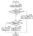
以下、図5のフローチャートを参照して、本実施形態の予備吐出実行位置の設定方法について説明する。図5に示したフローは、システムコントローラ301によって実行される。なお、本実施形態は、図3の光学的記録媒体検出装置110を備えていないインクジェット記録装置においても実施可能である。もちろん、光学的記録媒体検出装置を備えていても実施できる事は、自明である。
Hereinafter, the setting method of the preliminary discharge execution position of the present embodiment will be described with reference to the flowchart of FIG. The flow shown in FIG. 5 is executed by the
上記のように、ホストコンピュータからインクジェット記録装置に画像データと共に送信される制御データには、記録媒体のサイズや種類を特定するための情報が含まれている。本実施形態においては、この情報を取得することにより、予備吐出実行位置を設定する。 As described above, the control data transmitted together with the image data from the host computer to the ink jet recording apparatus includes information for specifying the size and type of the recording medium. In this embodiment, the preliminary discharge execution position is set by acquiring this information.
まず、ステップS501においてシステムコントローラ301がホストコンピュータ306から送信された制御データから記録媒体の情報を取得する。次に、ステップS502において取得した情報に含まれる記録媒体の種類及びサイズの情報に基づいて、表1に示すようなテーブルを参照し、予備吐出実行位置を設定する。
First, in step S <b> 501, the

本実施形態では、表1に示されるように、記録媒体の種類として高級光沢紙、廉価版光沢紙、普通紙及びCD−R/DVD−Rの4種類、記録媒体のサイズとしては、L版、はがき、A4、B4及びCD/DVDの5つを想定している。ここで、本実施形態のインクジェット記録装置では、高級光沢紙、廉価版光沢紙及び普通紙を用いる際には、ホームポジション側に寄せてセットし、CD―RやDVD―Rのレーベル面に記録する場合には、専用のトレイにCD―RやDVD―Rを載置して記録装置にセットするものとし、CD−RやDVD−Rはホームポジションの反対側に寄った状態でトレイに載置されるものとする。
記録媒体の種類が高級光沢紙、廉価版光沢紙、及び普通紙のいずれかであれば、記録媒体のサイズがL版やはがきであった場合には、基準となるホームポジション側に設けられたキャップ位置でのみ予備吐出を行ない、記録媒体のサイズがA4やB5である場合には、キャップ位置と予備吐出口との両方で予備吐出を行なうように設定する。一方、記録媒体の種類がCD−RやDVD−Rであれば、キャリッジの移動範囲においてホームポジションの反対側に設けられた予備吐出口のみで予備吐出を行うように設定する。
In this embodiment, as shown in Table 1, the recording medium types are four types of high-grade glossy paper, low-priced glossy paper, plain paper, and CD-R / DVD-R, and the size of the recording medium is the L plate. , Postcard, A4, B4, and CD / DVD are assumed. Here, in the inkjet recording apparatus of the present embodiment, when high-grade glossy paper, low-priced glossy paper, and plain paper are used, they are set close to the home position and recorded on the label surface of CD-R or DVD-R. In such a case, the CD-R or DVD-R is placed on a dedicated tray and set in the recording device, and the CD-R or DVD-R is placed on the tray in a state of being opposite to the home position. Shall be placed.
If the type of recording medium is one of high-grade glossy paper, low-priced glossy paper, or plain paper, and the size of the recording medium is an L plate or a postcard, it is provided on the reference home position side. When preliminary ejection is performed only at the cap position and the size of the recording medium is A4 or B5, the preliminary ejection is set at both the cap position and the preliminary ejection port. On the other hand, when the type of the recording medium is CD-R or DVD-R, the preliminary ejection is set only by the preliminary ejection port provided on the opposite side of the home position in the carriage movement range.
図4は、本実施形態で記録を行なう様子を説明する図であり、(a)はL版サイズの記録媒体に対する記録、(b)はCD−Rに対する記録の様子をそれぞれ示している。なお、図中、右端がホームポジション位置を示している。 4A and 4B are diagrams for explaining a state of recording in the present embodiment, where FIG. 4A shows recording on an L-size recording medium, and FIG. 4B shows recording on a CD-R. In the figure, the right end indicates the home position.
(a)では、ホームポジション側に寄せてL版の記録媒体がセットされているので、記録の際にキャリッジは、ホームポジション近辺とL版の左端との間で往復移動する。そして複数回の走査ごとに、ホームポジション側へ戻るタイミングで予備吐出が実行される。 In (a), since the L-size recording medium is set close to the home position side, the carriage reciprocates between the vicinity of the home position and the left end of the L plate during recording. Preliminary ejection is executed at the timing of returning to the home position side for each of a plurality of scans.
(b)では、ホームポジションの反対側に寄せてCD−Rがセットされているので、記録の際にキャリッジは、ホームポジションの反対側にある予備吐出口近辺とCD−Rの右端との間で往復移動する。そして、複数回の走査ごとに、予備吐出口側へ戻るタイミングで予備吐出が実行される。 In (b), since the CD-R is set close to the opposite side of the home position, the carriage moves between the vicinity of the preliminary discharge port on the opposite side of the home position and the right end of the CD-R during recording. Move back and forth. Then, for each of a plurality of scans, the preliminary discharge is executed at the timing of returning to the preliminary discharge port side.
このように本実施形態では、用いられる記録媒体の種類及びサイズとセットされる位置に基づいて、キャリッジが移動する範囲に近い位置で予備吐出が行なわれるように、予備吐出実行位置を設定する。 As described above, in this embodiment, the preliminary discharge execution position is set so that the preliminary discharge is performed at a position close to the range in which the carriage moves based on the type and size of the recording medium to be used and the set position.
なお、本実施形態においては、システムコントローラ301がホストコンピュータ306から受信した制御情報に含まれる記録媒体の情報に基づいて、予備吐出実行位置の設定を行っているが、ホストコンピュータ306にインストールされたプリンタドライバが、使用する記録媒体の種類及びサイズの情報に基づいて予備吐出実行位置を設定し、設定した予備吐出実行位置の情報を制御情報に含めてインクジェット記録装置に送信する形態としてもよい。
In the present embodiment, the preliminary discharge execution position is set based on the recording medium information included in the control information received from the
いずれにしても、記録に使用する記録媒体の情報に基づいて予備吐出実行位置を設定するようにすれば、本発明の範囲に含まれるものと理解されよう。 In any case, if the preliminary discharge execution position is set based on the information of the recording medium used for recording, it will be understood that it is included in the scope of the present invention.
以上説明したように本実施形態によれば、記録媒体のサイズや位置の情報に基づいて予備吐出実行位置が設定されるので、予備吐出実行位置の制御が簡略化されシステムコントローラの負荷が軽減され、処理速度の速い高価な部品を使用する必要がなくなり、コストが大幅に削減される。 As described above, according to the present embodiment, since the preliminary discharge execution position is set based on the information on the size and position of the recording medium, the control of the preliminary discharge execution position is simplified and the load on the system controller is reduced. This eliminates the need to use expensive parts with a high processing speed, thus greatly reducing the cost.
また、処理能力の低いインクジェット記録装置においても、スループットを落とすことなく予備吐出実行位置を適切に制御でき、従来の予備吐出位置選択処理を行なう場合と比較すると、スループットの向上も見込まれる。 Further, even in an ink jet recording apparatus having a low processing capability, the preliminary discharge execution position can be appropriately controlled without reducing the throughput, and an improvement in throughput can be expected as compared with the case where the conventional preliminary discharge position selection process is performed.
(第2の実施形態)
以下、本発明に係る第2の実施形態について説明する。第2の実施形態も第1の実施形態と同様なインクジェット記録装置であり、以下の説明では上記第1の実施形態と同様な部分については説明を省略し、第2の実施形態の特徴的な部分を中心に説明する。
(Second Embodiment)
Hereinafter, a second embodiment according to the present invention will be described. The second embodiment is also an ink jet recording apparatus similar to the first embodiment. In the following description, the description of the same parts as those of the first embodiment is omitted, and the characteristic of the second embodiment is described. The explanation will focus on the part.
本発明の第2の実施形態は、光学的記録媒体検出装置110を備えたインクジェット記録装置において、記録媒体検出装置からの出力から記録媒体のサイズ(幅)や位置の情報を取得し、これらの情報に基づいて、予備吐出実行位置を設定するものである。なお、本実施形態で用いる記録媒体検出装置は、図3に例示したものに限定されず、記録媒体の幅と位置が検出可能であれば様々な方式のものが使用可能である。
In the second embodiment of the present invention, in an ink jet recording apparatus provided with the optical recording
以下、図6のフローチャートを参照して、本実施形態の予備吐出実行位置の設定方法について説明する。図6に示したフローは、システムコントローラ301によって実行される。
Hereinafter, the setting method of the preliminary discharge execution position of the present embodiment will be described with reference to the flowchart of FIG. The flow shown in FIG. 6 is executed by the
まず、記録制御部301からの予備吐出信号を受信すると、予備吐出シーケンスが開始される。始めに、ステップS601で光学的記録媒体検出装置によって記録媒体の両端位置を検出し、記録媒体の走査方向のサイズ(幅)と、記録媒体が基準側(ホームポジション側)及び非基準側(ホームポジションの反対側)のいずれの側に寄せてセットされているのかを示す位置情報を取得する。
First, when a preliminary ejection signal is received from the
その後、ステップS602において、記録媒体の走査方向におけるサイズ(幅)がキャリッジの最大走査幅の半分以下であるか否かを判定する。記録媒体の幅が最大走査幅の半分を超えている(NO)場合には、ステップS606に進み、基準側(ホームポジション側)にあるキャップと素の反対側にある予備吐出口の両方で予備吐出を行うように設定する。 Thereafter, in step S602, it is determined whether or not the size (width) of the recording medium in the scanning direction is equal to or less than half of the maximum scanning width of the carriage. If the width of the recording medium exceeds half of the maximum scanning width (NO), the process proceeds to step S606, and the recording medium is reserved at both the cap on the reference side (home position side) and the preliminary discharge port on the opposite side of the element. Set to discharge.
ステップS602で記録媒体の幅が最大走査幅の半分以下である(YES)場合には、ステップS603に進み、ステップS601で取得した記録媒体の位置情報に基づいて、記録媒体が走査方向に対して基準側寄りにセットされているか否かを判定する。記録媒体が基準側寄りにセットされている(YES)場合は、ステップS604に進み、基準側のキャップにのみ予備吐出を行うように設定する。一方、記録媒体が基準側よりにセットされていない(NO)と判定された場合には、ステップS605に進み、記録媒体が反対側にセットされているものとして、予備吐出口のみに予備吐出を行なうように設定する。 If it is determined in step S602 that the width of the recording medium is less than or equal to half the maximum scanning width (YES), the process proceeds to step S603, and based on the position information of the recording medium acquired in step S601, the recording medium is in the scanning direction. It is determined whether it is set closer to the reference side. If the recording medium is set closer to the reference side (YES), the process proceeds to step S604, and setting is made so that preliminary ejection is performed only on the reference side cap. On the other hand, if it is determined that the recording medium is not set from the reference side (NO), the process proceeds to step S605, and it is assumed that the recording medium is set on the opposite side, and preliminary ejection is performed only on the preliminary ejection port. Set to do.
このように本実施形態では、記録媒体検出装置によって得られた記録媒体のサイズ及び位置の情報に基づいて、予備吐出実行位置を設定するが、その設定結果は第1の実施形態と同様となる。 As described above, in the present embodiment, the preliminary ejection execution position is set based on the information on the size and position of the recording medium obtained by the recording medium detection apparatus, and the setting result is the same as in the first embodiment. .
ただし、本実施形態では、記録媒体検出装置の実際の検出結果に基づいて設定するため、プリンタドライバでの記録媒体に関する設定が誤っているか否かについても判定できる。従って、プリンタドライバから送信された記録媒体の情報が実際に検出した結果と合っているか否かを判定して、異なる場合にはユーザにその旨通知することも可能であり、プリンタドライバでの設定が誤っている場合にも、適切な位置で予備吐出が実行される。 However, in this embodiment, since the setting is made based on the actual detection result of the recording medium detection device, it can also be determined whether or not the setting relating to the recording medium in the printer driver is incorrect. Therefore, it is possible to determine whether or not the information on the recording medium transmitted from the printer driver matches the actual detection result, and if it is different, it is possible to notify the user to that effect. Even if there is an error, preliminary ejection is performed at an appropriate position.
例えば、記録媒体検出装置で記録媒体の幅が最大走査幅の半分よりも幅が小さいL版の幅であると判定され、また、セット位置が基準側寄りであると判定された場合、図1の(a)と同様に、予備吐出実行位置は基準側のキャップのみに設定される。 For example, when it is determined by the recording medium detection apparatus that the width of the recording medium is the width of the L plate that is smaller than half the maximum scanning width, and the setting position is determined to be closer to the reference side, FIG. As in (a), the preliminary discharge execution position is set only to the reference-side cap.
以上説明したように本実施形態によれば、実際に検出した記録媒体のサイズ及び位置の情報に基づいて予備吐出実行位置が設定されるので、予備吐出実行位置の制御が簡略化されシステムコントローラの負荷が軽減され、処理速度の速い高価な部品を使用する必要がなくなり、コストが大幅に削減される。 As described above, according to the present embodiment, since the preliminary discharge execution position is set based on the actually detected information on the size and position of the recording medium, the control of the preliminary discharge execution position is simplified, and the system controller The load is reduced, it is not necessary to use expensive parts with high processing speed, and the cost is greatly reduced.
また、処理能力の低いインクジェット記録装置においても、スループットを落とすことなく予備吐出実行位置を適切に制御でき、従来の予備吐出位置選択処理を行なう場合と比較すると、スループットの向上も見込まれる。 Further, even in an ink jet recording apparatus having a low processing capability, the preliminary discharge execution position can be appropriately controlled without reducing the throughput, and an improvement in throughput can be expected as compared with the case where the conventional preliminary discharge position selection process is performed.
<他の実施形態>
以上説明した実施形態では、サーマル方式のインクジェット記録装置を例に挙げて説明をしたが、本発明は、インクの吐出方法の如何に関わらず応用が可能なものである。例えば、圧電素子を利用したピエゾ方式のインクジェット記録装置でも十分に効果を発揮するものである。
<Other embodiments>
In the embodiment described above, the thermal ink jet recording apparatus has been described as an example. However, the present invention can be applied regardless of the ink ejection method. For example, a piezo-type ink jet recording apparatus using a piezoelectric element can sufficiently exhibit the effect.
更に、本発明は、インクジェット記録装置だけでなく、インクジェット記録装置に対応した機能を実現する機器を含む複数の機器から構成される複合機やシステムに適用しても良い。 Furthermore, the present invention may be applied not only to an ink jet recording apparatus but also to a multifunction machine or system that includes a plurality of devices including devices that realize functions corresponding to the ink jet recording device.
なお、本発明は、前述した実施形態の機能を実現するソフトウェアのプログラム(上記の実施形態では図5又は図6に示すフローチャートに対応したプログラム)を、システム或いは装置に直接或いは遠隔から供給し、そのシステム或いは装置のコンピュータが該供給されたプログラムコードを読み出して実行することによっても達成される場合を含む。その場合、プログラムの機能を有していれば、形態は、プログラムである必要はない。 In the present invention, a software program for realizing the functions of the above-described embodiment (in the above-described embodiment, a program corresponding to the flowchart shown in FIG. 5 or 6) is directly or remotely supplied to the system or apparatus, This includes the case where the system or apparatus computer also achieves by reading and executing the supplied program code. In that case, as long as it has the function of a program, the form does not need to be a program.
従って、本発明の機能処理をコンピュータで実現するために、該コンピュータにインストールされるプログラムコード自体も本発明を実現するものである。つまり、本発明のクレームでは、本発明の機能処理を実現するためのコンピュータプログラム自体も含まれる。 Accordingly, since the functions of the present invention are implemented by computer, the program code installed in the computer also implements the present invention. That is, the claims of the present invention include the computer program itself for realizing the functional processing of the present invention.
その場合、プログラムの機能を有していれば、オブジェクトコード、インタプリタにより実行されるプログラム、OSに供給するスクリプトデータ等、プログラムの形態を問わない。 In this case, the program may be in any form as long as it has a program function, such as an object code, a program executed by an interpreter, or script data supplied to the OS.
プログラムを供給するための記録媒体としては、例えば、フレキシブルディスク、ハードディスク、光ディスク、光磁気ディスク、MO、CD−ROM、CD−R、CD−RW、磁気テープ、不揮発性のメモリカード、ROM、DVD(DVD−ROM,DVD−R)などがある。 As a recording medium for supplying the program, for example, flexible disk, hard disk, optical disk, magneto-optical disk, MO, CD-ROM, CD-R, CD-RW, magnetic tape, nonvolatile memory card, ROM, DVD (DVD-ROM, DVD-R).
その他、プログラムの供給方法としては、クライアントコンピュータのブラウザを用いてインターネットのホームページに接続し、該ホームページから本発明のコンピュータプログラムそのもの、もしくは圧縮され自動インストール機能を含むファイルをハードディスク等の記録媒体にダウンロードすることによっても供給できる。また、本発明のプログラムを構成するプログラムコードを複数のファイルに分割し、それぞれのファイルを異なるホームページからダウンロードすることによっても実現可能である。つまり、本発明の機能処理をコンピュータで実現するためのプログラムファイルを複数のユーザに対してダウンロードさせるWWWサーバも、本発明の範囲に含まれるものである。 As another program supply method, a client computer browser is used to connect to an Internet homepage, and the computer program of the present invention itself or a compressed file including an automatic installation function is downloaded from the homepage to a recording medium such as a hard disk. Can also be supplied. It can also be realized by dividing the program code constituting the program of the present invention into a plurality of files and downloading each file from a different homepage. That is, a WWW server that allows a plurality of users to download a program file for realizing the functional processing of the present invention on a computer is also included in the scope of the present invention.
また、本発明のプログラムを暗号化してCD−ROM等の記憶媒体に格納してユーザに配布し、所定の条件をクリアしたユーザに対し、インターネットを介してホームページから暗号化を解く鍵情報をダウンロードさせ、その鍵情報を使用することにより暗号化されたプログラムを実行してコンピュータにインストールさせて実現することも可能である。 In addition, the program of the present invention is encrypted, stored in a storage medium such as a CD-ROM, distributed to users, and key information for decryption is downloaded from a homepage via the Internet to users who have cleared predetermined conditions. It is also possible to execute the encrypted program by using the key information and install the program on a computer.
また、コンピュータが、読み出したプログラムを実行することによって、前述した実施形態の機能が実現される他、そのプログラムの指示に基づき、コンピュータ上で稼動しているOSなどが、実際の処理の一部または全部を行ない、その処理によっても前述した実施形態の機能が実現され得る。 In addition to the functions of the above-described embodiments being realized by the computer executing the read program, the OS running on the computer based on the instruction of the program is a part of the actual processing. Alternatively, the functions of the above-described embodiment can be realized by performing all of them and performing the processing.
さらに、記録媒体から読み出されたプログラムが、コンピュータに挿入された機能拡張ボードやコンピュータに接続された機能拡張ユニットに備わるメモリに書き込まれた後、そのプログラムの指示に基づき、その機能拡張ボードや機能拡張ユニットに備わるCPUなどが実際の処理の一部または全部を行ない、その処理によっても前述した実施形態の機能が実現される。 Furthermore, after the program read from the recording medium is written in a memory provided in a function expansion board inserted into the computer or a function expansion unit connected to the computer, the function expansion board or The CPU or the like provided in the function expansion unit performs part or all of the actual processing, and the functions of the above-described embodiments are realized by the processing.
101〜104 インクジェット記録ヘッド
105〜108 インクタンク(ブラック、シアン、マゼンタ、イエロー)
109 インクジェット記録ヘッドカートリッジ
190 ブラックインクジェット記録ヘッドユニット
191 カラーインクジェット記録ヘッドユニット
216 キャリッジ
218 タイミングベルト
219 ガイドシャフト
224 プラテン
225 予備吐出口
226 吸引回復用ポンプ
226a キャップ
301 システムコントローラ
302 ドライバ(主走査)
303 ドライバ(副走査)
304 モータ(キャリッジ走査)
305 モータ(記録媒体搬送)
306 ホストコンピュータ
307 受信バッファ
308 フレームメモリ
309 バッファ
310 記録制御部
311 ドライバ
101-104 Inkjet recording head 105-108 Ink tank (black, cyan, magenta, yellow)
109 Inkjet
303 Driver (sub-scan)
304 Motor (carriage scanning)
305 Motor (recording medium conveyance)
306
Claims (8)
記録とは無関係に前記記録ヘッドからインクを吐出させる予備吐出を行なう予備吐出手段と、
前記キャリッジの移動範囲内において前記予備吐出を行なう第1及び第2の予備吐出実行位置と、
前記キャリッジの移動範囲を前記記録媒体の種類に応じて異ならせて記録する記録手段と、
記録媒体のサイズ及び前記キャリッジの移動範囲の情報に基づいて、前記予備吐出手段による予備吐出を行なう位置を、前記キャリッジの移動範囲が所定の長さより長ければ前記第1及び第2の予備吐出実行位置の両方に設定し、前記所定の長さ以下であれば前記第1或は第2の予備吐出実行位置の内、前記キャリッジの移動範囲に近い方に設定する予備吐出位置設定手段と、を備えることを特徴とするインクジェット記録装置。 An inkjet recording apparatus that records on a plurality of types of recording media by scanning a carriage mounted with an inkjet recording head that ejects ink on the recording medium ,
Preliminary ejection means for performing preliminary ejection for ejecting ink from the recording head irrespective of recording;
First and second preliminary discharge execution positions for performing the preliminary discharge within a movement range of the carriage;
Recording means for recording the carriage in a different moving range depending on the type of the recording medium;
Based on information on the size of the recording medium and the movement range of the carriage, the first and second preliminary discharges are performed when the preliminary discharge by the preliminary discharge unit is performed at a position where the carriage movement range is longer than a predetermined length. Preliminary discharge position setting means that sets both of the positions and sets the first or second preliminary discharge execution position closer to the carriage movement range if the length is equal to or less than the predetermined length ; An ink jet recording apparatus comprising:
前記記録媒体のサイズ及び前記キャリッジの移動範囲の情報を、前記検出手段の検出結果から求めることを特徴とする請求項1に記載のインクジェット記録装置。 It further comprises detection means for detecting the end of the recording medium,
2. The ink jet recording apparatus according to claim 1, wherein information on a size of the recording medium and a moving range of the carriage is obtained from a detection result of the detection unit.
記録とは無関係に前記記録ヘッドからインクを吐出させる予備吐出を行なう位置として、前記キャリッジの移動範囲内において第1及び第2の予備吐出実行位置を設け、
前記キャリッジの移動範囲を記録媒体の種類に応じて異ならせて記録を行い、
記録媒体のサイズ及び前記キャリッジの移動範囲の情報に基づいて、前記予備吐出を行なう位置を、前記キャリッジの移動範囲が所定の長さより長ければ前記第1及び第2の予備吐出実行位置の両方に設定し、前記所定の長さ以下であれば前記第1或は第2の予備吐出実行位置の内、前記キャリッジの移動範囲に近い方に設定することを特徴とするインクジェット記録方法。 An inkjet recording method for performing recording on a plurality of types of recording media by scanning a carriage mounted with an inkjet recording head for discharging ink on the recording medium ,
The first and second preliminary ejection execution positions are provided within the movement range of the carriage as positions for performing preliminary ejection for ejecting ink from the recording head regardless of recording,
Recording is performed by changing the carriage movement range according to the type of recording medium,
Based on the information on the size of the recording medium and the movement range of the carriage, the position where the preliminary ejection is performed is set to both the first and second preliminary ejection execution positions if the carriage movement range is longer than a predetermined length. An ink jet recording method, wherein the ink jet recording method is set so as to be closer to the carriage movement range within the first or second preliminary discharge execution position if the length is equal to or shorter than the predetermined length .
Priority Applications (2)
| Application Number | Priority Date | Filing Date | Title |
|---|---|---|---|
| JP2004170450A JP4111517B2 (en) | 2004-06-08 | 2004-06-08 | Inkjet recording apparatus and inkjet recording method |
| US11/145,959 US7374267B2 (en) | 2004-06-08 | 2005-06-07 | Inkjet printing apparatus and inkjet printing method |
Applications Claiming Priority (1)
| Application Number | Priority Date | Filing Date | Title |
|---|---|---|---|
| JP2004170450A JP4111517B2 (en) | 2004-06-08 | 2004-06-08 | Inkjet recording apparatus and inkjet recording method |
Publications (3)
| Publication Number | Publication Date |
|---|---|
| JP2005349604A JP2005349604A (en) | 2005-12-22 |
| JP2005349604A5 JP2005349604A5 (en) | 2006-08-03 |
| JP4111517B2 true JP4111517B2 (en) | 2008-07-02 |
Family
ID=35584465
Family Applications (1)
| Application Number | Title | Priority Date | Filing Date |
|---|---|---|---|
| JP2004170450A Expired - Fee Related JP4111517B2 (en) | 2004-06-08 | 2004-06-08 | Inkjet recording apparatus and inkjet recording method |
Country Status (1)
| Country | Link |
|---|---|
| JP (1) | JP4111517B2 (en) |
Families Citing this family (3)
| Publication number | Priority date | Publication date | Assignee | Title |
|---|---|---|---|---|
| JP4802779B2 (en) * | 2006-03-13 | 2011-10-26 | コニカミノルタホールディングス株式会社 | Ink jet recording apparatus and nozzle recovery method for recording head |
| JP5288876B2 (en) * | 2008-05-08 | 2013-09-11 | キヤノン株式会社 | Recording apparatus and recording apparatus control method |
| JP2010214865A (en) | 2009-03-18 | 2010-09-30 | Canon Inc | Inkjet recorder and inkjet recording method |
-
2004
- 2004-06-08 JP JP2004170450A patent/JP4111517B2/en not_active Expired - Fee Related
Also Published As
| Publication number | Publication date |
|---|---|
| JP2005349604A (en) | 2005-12-22 |
Similar Documents
| Publication | Publication Date | Title |
|---|---|---|
| US7374267B2 (en) | Inkjet printing apparatus and inkjet printing method | |
| EP1604829B1 (en) | Inkjet printing apparatus and inkjet printing method | |
| JP4642533B2 (en) | Image forming system and recording control method of the system | |
| US7735946B2 (en) | Apparatus and method for ink jet printing | |
| JP4281807B2 (en) | Image processing apparatus, copying apparatus, image processing method and program thereof | |
| JP2009119793A (en) | Inkjet recording apparatus and recording method | |
| US8480198B2 (en) | Image forming apparatus, control method therefor, and medium storing program | |
| JP2010214865A (en) | Inkjet recorder and inkjet recording method | |
| JP4579557B2 (en) | Recording apparatus, control method therefor, and program | |
| JP4916293B2 (en) | Inkjet recording apparatus and inkjet recording method | |
| JP2005088242A (en) | Image forming apparatus and image forming method | |
| JP2005111982A (en) | Inkjet recording apparatus and recording method | |
| JP4111517B2 (en) | Inkjet recording apparatus and inkjet recording method | |
| JP5850667B2 (en) | Inkjet recording apparatus and inkjet recording method | |
| JP4743863B2 (en) | Inkjet recording apparatus and inkjet recording method | |
| JP4104512B2 (en) | Image forming apparatus | |
| JP2007136885A (en) | Inkjet recorder, and inkjet recording method | |
| JP2004209865A (en) | Image forming apparatus, program and record medium | |
| JP4924623B2 (en) | Image processing apparatus, copying apparatus, image processing method and program thereof | |
| JP2006168041A (en) | Inkjet-recording device, and inkjet-recording method | |
| JP2002361856A (en) | Apparatus and method for recording image | |
| JP2007136884A (en) | Inkjet recorder, and inkjet recording method | |
| JP2005349662A (en) | Recorder and method of recording | |
| JP2007021984A (en) | Ink-jet recorder | |
| JP2004268408A (en) | Recording system |
Legal Events
| Date | Code | Title | Description |
|---|---|---|---|
| A521 | Request for written amendment filed |
Free format text: JAPANESE INTERMEDIATE CODE: A523 Effective date: 20060620 |
|
| A621 | Written request for application examination |
Free format text: JAPANESE INTERMEDIATE CODE: A621 Effective date: 20060620 |
|
| A977 | Report on retrieval |
Free format text: JAPANESE INTERMEDIATE CODE: A971007 Effective date: 20070404 |
|
| A131 | Notification of reasons for refusal |
Free format text: JAPANESE INTERMEDIATE CODE: A131 Effective date: 20070409 |
|
| A521 | Request for written amendment filed |
Free format text: JAPANESE INTERMEDIATE CODE: A523 Effective date: 20070608 |
|
| TRDD | Decision of grant or rejection written | ||
| A01 | Written decision to grant a patent or to grant a registration (utility model) |
Free format text: JAPANESE INTERMEDIATE CODE: A01 Effective date: 20080404 |
|
| A61 | First payment of annual fees (during grant procedure) |
Free format text: JAPANESE INTERMEDIATE CODE: A61 Effective date: 20080407 |
|
| R150 | Certificate of patent or registration of utility model |
Ref document number: 4111517 Country of ref document: JP Free format text: JAPANESE INTERMEDIATE CODE: R150 Free format text: JAPANESE INTERMEDIATE CODE: R150 |
|
| FPAY | Renewal fee payment (event date is renewal date of database) |
Free format text: PAYMENT UNTIL: 20110418 Year of fee payment: 3 |
|
| FPAY | Renewal fee payment (event date is renewal date of database) |
Free format text: PAYMENT UNTIL: 20130418 Year of fee payment: 5 |
|
| FPAY | Renewal fee payment (event date is renewal date of database) |
Free format text: PAYMENT UNTIL: 20130418 Year of fee payment: 5 |
|
| FPAY | Renewal fee payment (event date is renewal date of database) |
Free format text: PAYMENT UNTIL: 20140418 Year of fee payment: 6 |
|
| LAPS | Cancellation because of no payment of annual fees |