JP4111184B2 - Shift control device for hybrid transmission - Google Patents
Shift control device for hybrid transmission Download PDFInfo
- Publication number
- JP4111184B2 JP4111184B2 JP2004301195A JP2004301195A JP4111184B2 JP 4111184 B2 JP4111184 B2 JP 4111184B2 JP 2004301195 A JP2004301195 A JP 2004301195A JP 2004301195 A JP2004301195 A JP 2004301195A JP 4111184 B2 JP4111184 B2 JP 4111184B2
- Authority
- JP
- Japan
- Prior art keywords
- speed
- driving force
- shift
- transient target
- target
- Prior art date
- Legal status (The legal status is an assumption and is not a legal conclusion. Google has not performed a legal analysis and makes no representation as to the accuracy of the status listed.)
- Expired - Fee Related
Links
Images


Classifications
-
- Y—GENERAL TAGGING OF NEW TECHNOLOGICAL DEVELOPMENTS; GENERAL TAGGING OF CROSS-SECTIONAL TECHNOLOGIES SPANNING OVER SEVERAL SECTIONS OF THE IPC; TECHNICAL SUBJECTS COVERED BY FORMER USPC CROSS-REFERENCE ART COLLECTIONS [XRACs] AND DIGESTS
- Y02—TECHNOLOGIES OR APPLICATIONS FOR MITIGATION OR ADAPTATION AGAINST CLIMATE CHANGE
- Y02T—CLIMATE CHANGE MITIGATION TECHNOLOGIES RELATED TO TRANSPORTATION
- Y02T10/00—Road transport of goods or passengers
- Y02T10/60—Other road transportation technologies with climate change mitigation effect
- Y02T10/62—Hybrid vehicles
-
- Y—GENERAL TAGGING OF NEW TECHNOLOGICAL DEVELOPMENTS; GENERAL TAGGING OF CROSS-SECTIONAL TECHNOLOGIES SPANNING OVER SEVERAL SECTIONS OF THE IPC; TECHNICAL SUBJECTS COVERED BY FORMER USPC CROSS-REFERENCE ART COLLECTIONS [XRACs] AND DIGESTS
- Y02—TECHNOLOGIES OR APPLICATIONS FOR MITIGATION OR ADAPTATION AGAINST CLIMATE CHANGE
- Y02T—CLIMATE CHANGE MITIGATION TECHNOLOGIES RELATED TO TRANSPORTATION
- Y02T10/00—Road transport of goods or passengers
- Y02T10/60—Other road transportation technologies with climate change mitigation effect
- Y02T10/7072—Electromobility specific charging systems or methods for batteries, ultracapacitors, supercapacitors or double-layer capacitors
Landscapes
- Electric Propulsion And Braking For Vehicles (AREA)
- Arrangement Of Transmissions (AREA)
- Hybrid Electric Vehicles (AREA)
- Control Of Driving Devices And Active Controlling Of Vehicle (AREA)
- Control Of Vehicle Engines Or Engines For Specific Uses (AREA)
- Control Of Transmission Device (AREA)
Description
本発明は、エンジン等の主動力源とモータ/ジェネレータとを搭載したハイブリッド車両に有用なハイブリッド変速機、特に、これら主動力源とモータ/ジェネレータとの間における差動装置により無段変速動作を行わせることが可能なハイブリッド変速機の変速制御装置に関するものである。 The present invention relates to a hybrid transmission useful for a hybrid vehicle equipped with a main power source such as an engine and a motor / generator, and in particular, a continuously variable transmission operation is performed by a differential device between the main power source and the motor / generator. The present invention relates to a shift control device for a hybrid transmission that can be performed.
この種ハイブリッド変速機としては例えば、遊星歯車組などにより構成した2自由度の差動装置を具え、該差動装置における回転メンバにそれぞれ主動力源であるエンジンからの入力、駆動系への出力、および複数個のモータ/ジェネレータを結合して、モータ/ジェネレータからの動力により無段変速を可能としたものが知られている。
かかるハイブリッド変速機においては、モータ/ジェネレータをバッテリからの電力により駆動するが、この駆動に際しては、通常の電気機器を駆動する場合と同様にモータ/ジェネレータをバッテリの定格電力以下で駆動する必要がある。
This type of hybrid transmission includes, for example, a two-degree-of-freedom differential device configured by a planetary gear set, and the like. And a plurality of motors / generators coupled to each other to enable a continuously variable transmission by power from the motor / generator.
In such a hybrid transmission, the motor / generator is driven by the electric power from the battery. In this driving, it is necessary to drive the motor / generator below the rated power of the battery as in the case of driving an ordinary electric device. is there.
バッテリの状態に応じてモータの駆動力を制御する技術としては従来、例えば特許文献1に記載のようなものが知られている。
この従来技術は、バッテリの充放電を伴って駆動するモータを動力源とした電気自動車を前提とするが、バッテリ残存容量あるいはバッテリ電圧が基準値以下に低下したり、バッテリ温度が基準値以上に上昇するなどして、バッテリ状態量が基準以上の変化を生じた時に、モータの駆動力指令に対する力制御の応答速度を遅くしてバッテリの早期劣化を防止しようとするものである。
This conventional technology is based on an electric vehicle that uses a motor driven by charging / discharging of the battery as a power source, but the remaining battery capacity or battery voltage drops below a reference value, or the battery temperature exceeds a reference value. When the battery state quantity changes more than the reference, for example, when it rises, the response speed of the force control with respect to the motor driving force command is slowed to prevent early deterioration of the battery.
しかし、本発明の前提となる前記した型式のハイブリッド変速機、つまり、2自由度の差動装置を介して主動力源(エンジン)からの入力と、駆動系への出力と、複数個のモータ/ジェネレータとの間を相互に結合し、モータ/ジェネレータからの動力により変速機入出力回転比(変速比)を無段階に変更(無段変速)可能にしたハイブリッド変速機に上記した従来の技術を用いて、バッテリ残存容量あるいはバッテリ電圧が基準値以下に低下したり、バッテリ温度が基準値以上に上昇するなどした時に、モータ/ジェネレータの指令に対する力制御の応答速度を遅くするような制御形態にすると以下の問題が発生する。 However, the hybrid transmission of the type described above that is the premise of the present invention, that is, an input from the main power source (engine), an output to the drive system, and a plurality of motors via a two-degree-of-freedom differential device. The conventional technology described above is applied to a hybrid transmission in which the transmission / output rotation ratio (transmission ratio) can be changed steplessly (continuously variable transmission) by the power from the motor / generator. Is used to slow down the response speed of the force control to the motor / generator command when the remaining battery capacity or battery voltage falls below the reference value or the battery temperature rises above the reference value. The following problems will occur.
つまり、この種ハイブリッド変速機においては、上記出力への駆動力と変速速度(入力回転加速度)とが相互に関係し合っており、従来のように変速速度(入力回転加速度)を考慮せずバッテリの状態のみに応じてモータ/ジェネレータの駆動力を制限すると、変速速度(入力回転加速度)が運転者の予期している方向とは逆になる可能性がある。
かように変速速度(入力回転加速度)が希望する方向とは逆のものになると、運転者が運転操作から予期しているとは逆の入力回転速度変化(エンジン回転速度変化)を生じて、運転者に違和感を抱かせる変速となる可能性があり、変速品質の低下を招くという問題が懸念される。
That is, in this type of hybrid transmission, the driving force to the output and the transmission speed (input rotational acceleration) are related to each other, and the battery speed is not considered in the conventional manner without considering the transmission speed (input rotational acceleration). If the driving force of the motor / generator is limited only in accordance with the state, there is a possibility that the shift speed (input rotational acceleration) is opposite to the direction expected by the driver.
Thus, when the shift speed (input rotational acceleration) is opposite to the desired direction, an input rotational speed change (engine rotational speed change) opposite to that expected by the driver is generated, There is a possibility that the speed change may make the driver feel uncomfortable, and there is a concern that the quality of the speed change may be reduced.
本発明は、目標駆動力および変速速度の組み合わせが実現可能領域内のものとなるよう修正して、これらを主動力源(エンジン)およびモータ/ジェネレータの制御に資することにより、実現可能領域から外れた目標駆動力および変速速度の組み合わせを主動力源(エンジン)およびモータ/ジェネレータの制御に資する場合に生ずるバッテリの劣化を防ぐが、
この修正を、変速速度が運転者の予期している方向とは逆になることのないように行って、上記した変速品質の低下に関する懸念を払拭し得るようにしたハイブリッド変速機の変速制御装置を提案することを主たる目的とする。
The present invention is modified so that the combination of the target driving force and the shift speed is within the feasible range, and these are used to control the main power source (engine) and the motor / generator. To prevent deterioration of the battery that occurs when the combination of the target driving force and the shifting speed contributes to the control of the main power source (engine) and the motor / generator,
The shift control apparatus for a hybrid transmission is made so that the speed change speed is not reversed from the direction expected by the driver, and the above-described concern about the deterioration of the speed change quality can be eliminated. The main purpose is to propose.
ところで上記の懸念を払拭するだけの対策では変速制御の過渡期において、変速制御機構の変速速度可能範囲を超えて変速用のエネルギーを多く与えすぎ、そのため駆動力用のエネルギーが不足して駆動力不足を生じたり、逆に、駆動力にエネルギーを使いすぎて変速速度が不足し、最低変速速度を実現できなくて実変速比を目標変速比に近づけることができないばかりか、実変速比が目標変速比から離れてしまう虞さえ生ずるという懸念があり、適合性に欠けるという問題がある。 By the way, in measures that only dispel the above concerns, in the transitional period of the shift control, too much shift energy is given beyond the allowable range of the shift speed of the shift control mechanism, and therefore the drive force energy is insufficient. Insufficiency, or conversely, too much energy is used for the driving force, the transmission speed is insufficient, the minimum transmission speed cannot be achieved, and the actual transmission ratio cannot be brought close to the target transmission ratio. There is a concern that even the gear ratio may deviate from the transmission ratio, and there is a problem of lack of compatibility.
本発明は、前記の懸念を払拭するだけでなく、上記の適合性に関する問題をも併せて解消したハイブリッド変速機の変速制御装置を提案することをも目的とする。 An object of the present invention is not only to eliminate the above-mentioned concerns but also to propose a shift control device for a hybrid transmission that solves the above-described problems relating to compatibility.
この目的のため、本発明によるハイブリッド変速機の変速制御装置は、請求項1に記載のごとくに構成する。
先ず前提となるハイブリッド変速機を説明するに、これは、
共線図上に配置される回転メンバとして複数個の回転メンバを有し、これら回転メンバのうち2個のメンバの回転状態を決定すると他のメンバの回転状態が決まる2自由度の差動装置を具え、前記複数個の回転メンバにそれぞれ、主動力源からの入力、駆動系への出力、および複数個のモータ/ジェネレータを結合し、これらモータ/ジェネレータからの動力を加減することにより、主動力源および駆動系間における変速比を無段階に変更可能なハイブリッド変速機である。
For this purpose, the shift control device for a hybrid transmission according to the present invention is constructed as described in claim 1.
First of all, to explain the prerequisite hybrid transmission,
A two-degree-of-freedom differential device having a plurality of rotating members as rotating members arranged on the nomograph, and determining the rotating state of the other members when the rotating state of two members is determined among these rotating members The plurality of rotating members are respectively coupled with an input from a main power source, an output to a drive system, and a plurality of motors / generators, and the power from these motors / generators is adjusted to adjust the main power. This is a hybrid transmission that can change the speed ratio between the power source and the drive system in a stepless manner.
本発明は、かかるハイブリッド変速機に対し、以下の静的目標駆動力演算手段と、初期過渡目標駆動力演算手段と、目標変速状態演算手段と、最低変速速度演算手段と、過渡目標値演算手段と、過渡目標値実現手段とを設ける。
静的目標駆動力演算手段は、運転状態に応じた前記駆動系への静的目標駆動力を演算するもので、
初期過渡目標駆動力演算手段は、この静的目標駆動力を基に、所定の時系列変化で駆動系への駆動力を該静的目標駆動力に向かわせるための初期過渡目標駆動力を演算するものである。
目標変速状態演算手段は、運転状態に応じた、主動力源および駆動系間の目標変速状態を演算するもので、
最低変速速度演算手段は、この目標変速状態へ実変速状態を収束させる変速速度の最低値を規定した最低変速速度を演算するものである。
The present invention relates to such a hybrid transmission with the following static target driving force calculation means, initial transient target driving force calculation means, target shift state calculation means, minimum shift speed calculation means, and transient target value calculation means. And a transient target value realization means.
The static target driving force calculating means calculates a static target driving force to the driving system according to the driving state,
The initial transient target driving force calculation means calculates the initial transient target driving force for directing the driving force to the driving system toward the static target driving force with a predetermined time-series change based on the static target driving force. To do.
The target shift state calculating means calculates a target shift state between the main power source and the drive system according to the driving state.
The minimum shift speed calculating means calculates a minimum shift speed that defines the minimum value of the shift speed for converging the actual shift state to the target shift state.
過渡目標値演算手段は、モータ/ジェネレータ、該モータ/ジェネレータ用のバッテリおよび主動力源の現状で実現可能な、駆動力および変速速度の組み合わせに関した、これら駆動力および変速速度の二次元座標上における実現可能領域内で前記最低変速速度以上の変速速度を確保できるように前記初期過渡目標駆動力を修正して過渡目標駆動力を求めると共に、該修正後の過渡目標駆動力のもとで前記実現可能領域内に居続けるための変速速度可能範囲を求めるものである。
そして過渡目標値実現手段は、上記過渡目標駆動力を実現すると共に上記変速速度可能範囲内の変速速度で前記目標変速状態および実変速状態間の変速状態偏差を減らすよう主動力源およびモータ/ジェネレータを制御するものである。
The transient target value calculation means is based on the two-dimensional coordinates of the driving force and the shifting speed related to the combination of the driving force and the shifting speed that can be realized in the current state of the motor / generator, the battery for the motor / generator, and the main power source. The initial transient target driving force is corrected to obtain a transient target driving force so that a shifting speed equal to or higher than the minimum shifting speed can be secured within the feasible region in the above, and the transient target driving force is corrected under the corrected transient target driving force. The speed change speed possible range for staying in the feasible region is obtained.
The transient target value realizing means realizes the transient target driving force and reduces the shift state deviation between the target shift state and the actual shift state at a shift speed within the shift speed possible range. Is to control.
上記の構成になるハイブリッド変速機の変速制御装置によれば、実現可能領域内で前記最低変速速度以上の変速速度を確保できるように初期過渡目標駆動力を修正して過渡目標駆動力を求めると共に、該修正後の過渡目標駆動力のもとで実現可能領域内に居続けるための変速速度可能範囲を求め、
上記過渡目標駆動力を実現すると共に上記変速速度可能範囲内の変速速度で前記目標変速状態および実変速状態間の変速状態偏差を減らすよう主動力源およびモータ/ジェネレータを制御するため、
実現可能領域から外れた初期過渡目標駆動力をそのまま主動力源およびモータ/ジェネレータの制御に資する場合に生ずるバッテリの劣化を防ぐことができると共に、
上記過渡目標駆動力を実現すると共に上記変速速度可能範囲内の変速速度で前記目標変速状態および実変速状態間の変速状態偏差を減らすよう主動力源およびモータ/ジェネレータを制御しても、駆動力および変速速度が運転者の予期している方向とは逆になることがなく、
運転者が運転操作から予期しているとは逆の駆動力変化や変速速度変化を生ずる事態を回避し、運転者に違和感を抱かせる変速となる懸念を払拭することができる。
According to the shift control device for a hybrid transmission configured as described above, the initial transient target drive force is corrected to obtain the transient target drive force so that a shift speed equal to or higher than the minimum shift speed can be secured within the feasible region. , To determine the speed change possible range to continue to be within the realizable area under the corrected transient target driving force,
In order to control the main power source and the motor / generator so as to realize the transient target driving force and reduce a shift state deviation between the target shift state and the actual shift state at a shift speed within the shift speed possible range,
It is possible to prevent deterioration of the battery that occurs when the initial transient target driving force deviating from the feasible region directly contributes to the control of the main power source and the motor / generator.
Even if the main power source and the motor / generator are controlled to realize the transient target driving force and reduce the shift state deviation between the target shift state and the actual shift state at a shift speed within the shift speed possible range, And the shifting speed is not reversed from the direction the driver expects,
It is possible to avoid a situation in which a change in driving force or a change in shift speed that is opposite to what the driver expects from the driving operation is avoided, and to eliminate the concern of a shift that makes the driver feel uncomfortable.
更に加えて本発明の構成によれば、最低変速速度の実現に必要なパワーを確保した上で初期過渡目標駆動力にできるだけ近い駆動力を確保し、この駆動力を除いた残り全てのパワーを変速速度可能範囲と定め、この範囲内の速度で変速を行わせることになるから、
最低変速速度を含むこの変速速度可能範囲で、目標変速状態および実変速状態間の変速状態偏差のみを考慮したロバストな制御系が、滑らかで且つ変速状態偏差を確実に減らすような変速速度を設定することができ、これにより、目標変速状態および実変速状態間のずれが大きくなってしまうような懸念をなくし得る。
つまり、駆動力にエネルギーを使いすぎ変速速度の不足により最低変速速度を実現できなくて実変速状態を目標変速状態に近づけることができなくなったり、実変速状態が目標変速状態から離れてしまう虞をなくし得る。
逆に、変速制御機構の変速速度可能範囲を超えて変速用のエネルギーを多く与えすぎ、そのため駆動力用のエネルギーが不足して駆動力不足を生ずるようなこともない。
In addition, according to the configuration of the present invention, the power necessary for realizing the minimum shift speed is secured, the driving force as close as possible to the initial transient target driving force is secured, and all the remaining power except the driving force is obtained. Since it is determined that the speed change speed is within the range and the speed is changed within this range,
A robust control system that takes into account only the shift state deviation between the target shift state and the actual shift state within this possible shift speed range, including the minimum shift speed, sets a shift speed that is smooth and reliably reduces the shift state deviation. This can eliminate the concern that the difference between the target shift state and the actual shift state becomes large.
That is, there is a possibility that the actual shift state cannot be brought close to the target shift state or the actual shift state is separated from the target shift state because the minimum shift speed cannot be realized due to excessive use of energy in the driving force and the shift speed is insufficient. It can be lost.
On the other hand, there is no possibility that a large amount of energy for shifting is applied beyond the shift speed possible range of the shift control mechanism, so that the energy for driving force is insufficient and the driving force is insufficient.
また、過渡目標駆動力を決めると残りのパワーが全て変速に使える量となり、これにより決まる変速速度可能範囲内で変速状態偏差に応じた変速速度が自動的に決定される構成であるため、
適合要素が過渡目標駆動力だけとなり、適合工数の削減によって適合性を大いに高めることができる。
In addition, when the transient target driving force is determined, the remaining power becomes an amount that can be used for shifting, and the shift speed according to the shift state deviation is automatically determined within the shift speed possible range determined thereby,
The conforming element is only the transient target driving force, and the conformity can be greatly enhanced by reducing the conforming man-hours.
以下、本発明の実施の形態を、図面に示す実施例に基づき詳細に説明する。
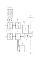
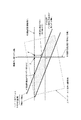
図1(a)は、本発明の一実施例になる変速制御装置を適用可能なハイブリッド変速機を例示し、これを本実施例においては前輪駆動車(FF車)用のトランスアクスルとして構成する。
図において1は変速機ケースを示し、該変速機ケース1の軸線方向(図の左右方向)左側にラビニョオ型プラネタリギヤセット2を、また図の右側に複合電流2層モータ3を内蔵させる。
ラビニョオ型プラネタリギヤセット2の更に左側には、変速機ケース1の外側であるが、エンジン(主動力源)ENGを配置する。
Hereinafter, embodiments of the present invention will be described in detail based on examples shown in the drawings.
FIG. 1A illustrates a hybrid transmission to which a shift control apparatus according to an embodiment of the present invention can be applied, and this is configured as a transaxle for a front wheel drive vehicle (FF vehicle) in this embodiment. .
In the figure, reference numeral 1 denotes a transmission case, in which a Ravigneaux type
On the further left side of the Ravigneaux-type
ラビニョオ型プラネタリギヤセット2、エンジンENG、および複合電流2層モータ3は、ハイブリッド変速機の主軸線上に同軸に配置して変速機ケース1内に取り付けるが、変速機ケース1内には更に、上記の主軸線からオフセットさせて平行に配置したカウンターシャフト6およびディファレンシャルギヤ装置7をも内蔵させ、
ディファレンシャルギヤ装置7に左右駆動車輪8を駆動結合する。
The Ravigneaux type
The left and
ラビニョオ型プラネタリギヤセット2は、ロングピニオンP2を共有する2つのシングルピニオン遊星歯車組4,5の組み合わせになり、エンジンENGに近い側に配置された方を第1のシングルピニオン遊星歯車組4とし,他方を第2のシングルピニオン遊星歯車組5とする。
第1のシングルピニオン遊星歯車組4はサンギヤS2およびリングギヤR2にそれぞれロングピニオンP2を噛合させた構造とし、
第2のシングルピニオン遊星歯車組5は、共有ピニオンP2の他に、サンギヤS1およびリングギヤR1と、これらに噛合した大径のショートピニオンP1を有し、当該ショートピニオンP1を共有ピニオンP2に噛合させた構造とする。
そして遊星歯車組4,5のピニオンP1,P2を全て、共通なキャリアCにより回転自在に支持する。
The Ravigneaux
The first single pinion planetary gear set 4 has a structure in which a long pinion P2 is engaged with the sun gear S2 and the ring gear R2, respectively.
The second single pinion planetary gear set 5 has a sun gear S1 and a ring gear R1 in addition to the shared pinion P2, and a large-diameter short pinion P1 meshed therewith, and meshes the short pinion P1 with the shared pinion P2. Structure.
All the pinions P1 and P2 of the planetary gear sets 4 and 5 are rotatably supported by a common carrier C.
以上の構成になるラビニョオ型プラネタリギヤセット2は、サンギヤS1、サンギヤS2、リングギヤR2、およびキャリアCの4個の回転メンバを主たる要素とし、これら4個のメンバのうち2個のメンバの回転速度を決定すると他のメンバの回転速度が決まる2自由度の差動装置を構成する。
そして4個の回転メンバの回転速度順は、図1(b)の共線図に示すごとく、サンギヤS1、リングギヤR2、キャリアC、サンギヤS2の順番である。
The Ravigneaux type planetary gear set 2 having the above-described configuration has four rotating members of the sun gear S1, the sun gear S2, the ring gear R2, and the carrier C as main elements, and the rotational speed of two of these four members is When determined, a differential device having two degrees of freedom in which the rotational speed of other members is determined is formed.
The rotational speed order of the four rotating members is the order of the sun gear S1, the ring gear R2, the carrier C, and the sun gear S2, as shown in the alignment chart of FIG.
複合電流2層モータ3は、内側ロータ3riと、これを包囲する環状の外側ロータ3roとを、変速機ケース1内に同軸に回転自在に支持して具え、これら内側ロータ3riおよび外側ロータ3ro間における環状空間に同軸に配置した環状ステータ3sを変速機ケース1に固設して構成する。
環状コイル3sと内側ロータ3riとで内側のモータ/ジェネレータである第1のモータ/ジェネレータMG1を構成し、環状コイル3sと外側ロータ3roとで外側のモータ/ジェネレータである第2のモータ/ジェネレータMG2を構成する。
ここでモータ/ジェネレータMG1,MG2はそれぞれ、複合電流をモータ側が負荷として供給される時は供給電流に応じた個々の方向と速度(停止を含む)の回転を出力するモータとして機能し、複合電流を発電機側が負荷として印加した時は外力による回転に応じた電力を発生する発電機として機能する。
The composite current two-layer motor 3 includes an inner rotor 3ri and an annular outer rotor 3ro that surrounds the inner rotor 3ri so as to be coaxially rotatable in the transmission case 1 and between the inner rotor 3ri and the outer rotor 3ro. An
The
Here, each of the motor / generators MG1 and MG2 functions as a motor that outputs the rotation of each direction and speed (including stop) according to the supplied current when the combined current is supplied as a load on the motor side. When the generator side is applied as a load, it functions as a generator that generates electric power according to the rotation by an external force.
ラビニョオ型プラネタリギヤセット2の上記した4個の回転メンバには、回転速度順に、つまり図1(b)の共線図にも示したが、サンギヤS1、リングギヤR2、キャリアC、サンギヤS2の順に、第1のモータ/ジェネレータMG1、主動力源であるエンジンENGからの入力、車輪駆動系への出力(Out)、第2のモータ/ジェネレータMG2を結合する。 The above four rotating members of the Ravigneaux planetary gear set 2 are shown in order of rotational speed, that is, in the collinear diagram of FIG. 1B, but in the order of the sun gear S1, the ring gear R2, the carrier C, and the sun gear S2. The first motor / generator MG1, the input from the engine ENG as the main power source, the output (Out) to the wheel drive system, and the second motor / generator MG2 are coupled.
この結合を図1(a)に基づき以下に詳述するに、リングギヤR2を上記の通りエンジン回転が入力される入力要素とするため、このリングギヤR2にエンジンENGのクランクシャフトを結合する。
サンギヤS1は、これからエンジンENGと反対の後方へ延在する中空軸11を介して第1のモータ/ジェネレータMG1(ロータ4ri)に結合し、このモータ/ジェネレータMG1および中空軸11を遊嵌する中心軸12を介してサンギヤS2を第2のモータ/ジェネレータMG2(ロータ4ro)に結合する。
This coupling will be described in detail below with reference to FIG. 1A. In order to use the ring gear R2 as an input element for inputting engine rotation as described above, the crankshaft of the engine ENG is coupled to the ring gear R2.
The sun gear S1 is coupled to the first motor / generator MG1 (rotor 4ri) via a hollow shaft 11 extending rearward opposite to the engine ENG, and a center for loosely fitting the motor / generator MG1 and the hollow shaft 11. The sun gear S2 is coupled to the second motor / generator MG2 (rotor 4ro) via the
キャリアCを前記のごとく、車輪駆動系へ回転を出力する出力要素とするため、このキャリアCに中空のコネクティングメンバ(出力軸)13を介して出力歯車14を結合し、これをラビニョオ型プラネタリギヤセット2および複合電流2層モータ3間に配置して変速機ケース1内に回転自在に支持する。
出力歯車14は、カウンターシャフト6上のカウンター歯車15に噛合させ、出力歯車14からの変速機出力回転が、カウンター歯車15を経由し、その後、カウンターシャフト6を経てディファレンシャルギヤ装置7に至り、このディファレンシャルギヤ装置により左右駆動車輪8に分配されるものとし、これらで車輪駆動系を構成する。
In order to use the carrier C as an output element that outputs rotation to the wheel drive system as described above, the
The
上記の構成になるハイブリッド変速機は図1(b)に示すような共線図により表すことができ、この共線図の横軸は遊星歯車組4,5のギヤ比により決まる回転メンバ間の距離の比、つまりリングギヤR2およびキャリアC間の距離を1とした時のサンギヤS1およびリングギヤR2間の距離の比をαで示し、キャリアCおよびサンギヤS2間の距離をβで示したものである。
また共線図の縦軸は、各回転メンバの回転速度、つまりリングギヤR2へのエンジン回転数ωE(変速機入力回転数ωi)、サンギヤS1(モータ/ジェネレータMG1)の回転数ω1、キャリアCからの変速機出力(Out)回転数ωo、およびサンギヤS2(モータ/ジェネレータMG2)の回転数ω2を示し、2個の回転メンバの回転速度が決まれば他の2個の回転メンバの回転速度が決まる。
The hybrid transmission configured as described above can be represented by a collinear diagram as shown in FIG. 1 (b), and the horizontal axis of this collinear diagram is between the rotating members determined by the gear ratio of the planetary gear sets 4 and 5. The distance ratio, that is, the distance ratio between the sun gear S1 and the ring gear R2 when the distance between the ring gear R2 and the carrier C is 1, is denoted by α, and the distance between the carrier C and the sun gear S2 is denoted by β. .
The vertical axis of the collinear diagram, the rotational number omega 1 of the rotational speed of each rotating member, i.e. engine speed omega E to the ring gear R2 (transmission input rotation speed omega i), the sun gear S1 (the motor / generator MG1), The transmission output (Out) rotation speed ω o from the carrier C and the rotation speed ω 2 of the sun gear S2 (motor / generator MG2) are shown. If the rotation speeds of the two rotation members are determined, the other two rotation members The rotation speed is determined.
図1(b)の共線図により上記ハイブリッド変速機の変速動作を以下に説明するに、前進(正)回転出力時の変速動作としてEVモードおよびEIVTモードの2モードが存在し、後退(逆)回転出力用のREV変速動作が存在する。
EVモードは、図1(b)にレバーEVにより例示するごとく、エンジンENGを停止した状態で、両モータ/ジェネレータMG1,MG2(または一方のモータ/ジェネレータ)からの動力のみにより駆動系への出力Outを決定する。
EIVTモードは、図1(b)にレバーEIVTにより例示するごとく、エンジンENGからの動力および両モータ/ジェネレータMG1,MG2(または一方のモータ/ジェネレータ)からの動力により駆動系への出力Outを決定する。
The shifting operation of the hybrid transmission will be described below with reference to the collinear diagram of FIG. 1B. There are two modes, EV mode and EIVT mode, as the shifting operation at the time of forward (forward) rotation output, and the reverse (reverse) ) There is a REV shift operation for rotational output.
In EV mode, as shown by lever EV in Fig. 1 (b), output to the drive system is based only on the power from both motors / generators MG1, MG2 (or one motor / generator) with engine ENG stopped. Determine Out.
In the EIVT mode, as illustrated by lever EIVT in Fig. 1 (b), the output Out to the drive system is determined by the power from the engine ENG and the power from both motors / generators MG1, MG2 (or one motor / generator). To do.
後退(逆)回転出力用のREV変速動作は、図1(b)にレバーREVとして示すように、エンジンENGからの動力に依存することなく、モータ/ジェネレータMG1の正回転、またはモータ/ジェネレータMG2の逆回転、或いはこれら双方により、キャリアCから出力(Out)へ逆回転が出力される変速状態である。 The REV speed change operation for the reverse (reverse) rotation output does not depend on the power from the engine ENG or the motor / generator MG2 or the motor / generator MG2 as shown by the lever REV in FIG. Is the speed change state in which the reverse rotation is output from the carrier C to the output (Out) by the reverse rotation or both of them.
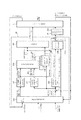
上記した各モードでの変速動作制御を行うハイブリッド変速機の変速制御システムは図2に示すごとくに構成する。
21は、エンジンENGおよびハイブリッド変速機の統合制御を司るハイブリッドコントローラ21で、このハイブリッドコントローラ21はエンジンENGの目標力T* Eおよび目標回転数ω* E(目標入力回転数ω* i)に関する指令をエンジンコントローラ22に供給し、エンジンコントローラ22はエンジンENGを当該目標値T* Eおよびω* E(ω* i)が達成されるよう運転させる。
The shift control system for the hybrid transmission that controls the shift operation in each mode described above is configured as shown in FIG.
ハイブリッドコントローラ21は更に、モータ/ジェネレータMG1,MG2の目標力T* 1,T* 2に関する指令信号をモータコントローラ23に供給し、モータコントローラ23はインバータ24およびバッテリ25によりモータ/ジェネレータMG1,MG2をそれぞれ、上記した目標力T* 1,T* 2が達成されるよう制御する。
The
ハイブリッドコントローラ21には、アクセルペダル踏み込み量からアクセル開度APOを検出するアクセル開度センサ26からの信号と、車速VSP(出力回転数ωOに比例)を検出する車速センサ27からの信号と、エンジン回転数ωE(入力回転数ωi)を検出するエンジン回転センサ28からの信号とを入力する。
ハイブリッドコントローラ21は、アクセルペダル踏み込み量APOおよび車速VSPから求め得る要求駆動力P* o、車速VSP、およびバッテリ25の蓄電状態SOC(持ち出し可能電力)から運転者が希望する運転状態を実現するように、モード選択を行うと共に選択モードに応じた変速制御を実行して、上記した目標エンジン力T* E、目標エンジン回転数ω* E(ω* i)、および目標モータ/ジェネレータ力T* 1,T* 2を決定して指令するものとする。
The
The
なおハイブリッドコントローラ21に入力する回転速度情報は、上記したエンジン回転数ωE(ωi)および車速VSP(出力回転数ωO)に限られるものではなく、ラビニョオ型プラネタリギヤセット2で構成する差動装置が2自由度のものであることから、当該ラビニョオ型プラネタリギヤセット2内における回転メンバのいずれか2個の回転速度をハイブリッドコントローラ21に入力してもよい。
Note that the rotational speed information input to the
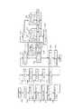
図3は、ハイブリッドコントローラ21の機能別ブロック線図を示し、ハイブリッドコントローラ21は、静的目標値演算手段101と、初期過渡目標駆動力演算手段102と、最低変速速度演算手段103と、理想変速速度演算手段104と、過渡目標値演算手段105と、エンジン回転(入力回転)サーボ制御手段106と、モータ制御手段107と、エンジン制御手段108とで構成する。
FIG. 3 is a functional block diagram of the
静的目標値演算手段101は、アクセルペダル踏み込み量APOと、車速VSPと、バッテリ蓄電状態SOC(持ち出し可能電力)と、エンジン回転数ωEとから、以下のようにして車輪駆動系への静的目標駆動力(以下、力はトルクを意味する)T* oOと、静的目標エンジン回転数ω* E(静的目標入力回転数ω* i)と、静的目標エンジン力T* EOとを演算する。
従って静的目標値演算手段101は、本発明における静的目標駆動力演算手段、および、目標変速状態演算手段(変速状態は、変速比に代表されるように、車速VSPを一定とすると入力回転であるエンジン回転数として捉えられるため)に相当する。
なお車速VSPは、例えば出力軸回転速度ωoから次式を用いて演算される。
VSP=kv・ωo・・・(1)
ここで、kvは、タイヤ半径やファイナルギヤ比により決まる定数である。
Static target
Therefore, the static target value calculation means 101 is equivalent to the static target driving force calculation means and the target shift state calculation means in the present invention (if the vehicle speed VSP is constant as represented by the gear ratio, Is equivalent to the engine speed).
The vehicle speed VSP is calculated from the output shaft rotational speed ω o using the following equation, for example.
VSP = k v・ ω o・ ・ ・ (1)
Here, kv is a constant determined by the tire radius and final gear ratio.
静的目標値演算手段101は先ず、アクセルペダル踏み込み量APOと車速VSPとから、図4に示す駆動力マップを用いて、変速機出力歯車14への目標駆動力T* oOを算出する。
次に、次式を用いて目標駆動力T* Oと出力回転数ωoとから、目標駆動動力P* oを演算する。
P* o=ωo・T* O・・・ (1)
次に、バッテリ蓄電状態SOC(持ち出し可能電力)から、例えば、SOCが高いほどバッテリ放電量を多くし、SOCが低いほどバッテリ充電量を多くするように、目標バッテリ充放電量P* Bを決める。
First, the static target value calculating means 101 calculates a target driving force T * oO to the
Next, the target drive power P * o is calculated from the target drive force T * O and the output rotational speed ω o using the following equation.
P * o = ω o · T * O (1)
Next, from the battery storage state SOC (carryable power), for example, the target battery charge / discharge amount P * B is determined so that the battery discharge amount increases as the SOC increases and the battery charge amount increases as the SOC decreases. .
最後に、目標駆動動力P* oと、エンジン回転数ωiと、目標バッテリ充放電量P* Bとから、静的目標エンジン回転数ω* iと、静的目標エンジン力T* EOとを、例えば以下のように演算する。
先ず、目標エンジンパワーP* Eと、目標駆動動力P* oと、目標バッテリ充放電量P* Bとが次式で表される関係になるよう目標エンジンパワーP* Eを設定する。
P* E=P* o+P* B・・・ (2)
次に、この目標エンジンパワーP* Eをエンジンで発生させるとき燃費最適となる目標エンジン回転速度ω* Eを、図5に示す燃費最適目標エンジン回転速度マップを用いて、目標エンジンパワーP* Eから検索する。
Finally, from the target drive power P * o , the engine speed ω i, and the target battery charge / discharge amount P * B , the static target engine speed ω * i and the static target engine power T * EO are obtained. For example, the calculation is performed as follows.
First, set a target engine power P * E, and the target driving power P * o, a target engine power P * E so that the the target battery charge and discharge amount P * B a relationship expressed by the following equation.
P * E = P * o + P * B (2)
Then, the target engine rotational speed omega * E as the optimum fuel consumption when generating the target engine power P * E engine using a fuel consumption optimum target engine rotational speed map shown in FIG. 5, the target engine power P * E Search from.
目標エンジンパワーP* Eをエンジンで供給すると共にエンジン動作点を燃費最適点にするためには、目標エンジンパワーP* Eを目標エンジン回転数ω* Eで除算した値を目標エンジン力T* Eとする考え方がある。
しかし、後述する目標値修正手段103により、変速過渡時においてエンジン回転加速度が制限される場合があり、この場合、目標エンジン回転数ω* Eが実現されなくなる。
このように目標エンジン回転数ω* Eが実現されない場合、目標エンジンパワーP* Eが得られなくなる。
そこで、目標エンジン力T* E0 は次式で表されるように、目標エンジンパワーP* E を実際のエンジン回転数ωiで除した値とする。
T* E0=P* E /ωi・・・(3)
ここで、定常時などのように目標エンジン回転数ω* Eと実際のエンジン回転数ωEとが合っていれば、エンジン力は燃費最適なエンジン力となる。
The target engine power P * E for the optimum fuel consumption point of the engine operating point is supplied by the engine, the target engine power P * E target engine speed omega * E in dividing the value of the target engine power T * E There is a way of thinking.
However, there is a case where the engine rotation acceleration is limited during the shift transition by the target value correcting means 103 described later, and in this case, the target engine speed ω * E cannot be realized.
Thus, when the target engine speed ω * E is not realized, the target engine power P * E cannot be obtained.
Therefore, the target engine power T * E0 is a value obtained by dividing the target engine power P * E by the actual engine speed ω i as expressed by the following equation.
T * E0 = P * E / ω i ··· (3)
Here, if the target engine speed ω * E matches the actual engine speed ω E as in a normal state, the engine power becomes the optimum engine power for fuel consumption.
初期過渡目標駆動力演算手段102は、上記のごとくに求めた静的目標駆動力T* o0を基に、駆動系への駆動力を所定の時系列変化で静的目標駆動力T* o0に向かわせるための初期過渡目標駆動力T* o1を求める。
上記駆動力に関する所定の時系列変化は、実験やシミュレーションにより最適なものを予め求めておく過渡特性で、例えば車速VSPやアクセル開度APOに応じ時定数の異なる二次遅れのフィルタを用いて静的目標駆動力T* o0から初期過渡目標駆動力T* o1は求めることができる。
Based on the static target driving force T * o0 obtained as described above, the initial transient target driving force calculating means 102 converts the driving force to the driving system to the static target driving force T * o0 with a predetermined time series change. The initial transient target driving force T * o1 to be directed is obtained.
The predetermined time series change related to the driving force is a transient characteristic obtained in advance by experiments and simulations. For example, a static delay using a second-order lag filter having a different time constant according to the vehicle speed VSP and the accelerator opening APO is used. The initial transient target driving force T * o1 can be determined from the target driving force T * o0 .
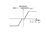
最低変速速度演算手段103は、運転状態ごとに予め求めておいた最低限必要な変速速度、つまり、変速比や入力回転数ωi(エンジン回転数ωE)などの実変速状態を、静的目標変速比や静的目標入力回転数ω* i(静的目標エンジン回転数ω* E)などの目標変速状態に収束させる時に最低限必要な最低変速速度を最低エンジン回転加速度ΔωEminとして求める。
具体的には、例えば図6に例示するように、静的目標エンジン回転数ω* Eおよび実エンジン回転数ωE間におけるエンジン回転偏差ΔωE(=ω* E−ωE)、つまり変速状態偏差に関する変化特性として予め設定しておいた最低変速速度(最低エンジン回転加速度ΔωEmin)のデータマップを基にエンジン回転偏差ΔωEから検索して最低変速速度(最低エンジン回転加速度ΔωEmin)を求める。
The minimum shift speed calculation means 103 statically determines the minimum required shift speed obtained in advance for each driving state, that is, the actual shift state such as the gear ratio and the input speed ω i (engine speed ω E ). The minimum speed required for convergence to the target speed change state such as the target gear ratio and the static target input speed ω * i (static target engine speed ω * E ) is obtained as the minimum engine speed acceleration Δω Emin .
Specifically, as illustrated in FIG. 6, for example, the engine rotational deviation Δω E (= ω * E −ω E ) between the static target engine speed ω * E and the actual engine speed ω E , that is, the shift state determining a minimum transmission speed (minimum engine revolution acceleration [Delta] [omega Emin) based on the data map of the minimum transmission rate set in advance as the change characteristic related to a deviation (minimum engine acceleration [Delta] [omega Emin) retrieved from the engine speed deviation [Delta] [omega E .
理想変速速度演算手段104は、運転状態ごとに予め求めておいた最適な変速速度、つまり、変速比や入力回転数ωi(エンジン回転数ωE)などの実変速状態を、静的目標変速比や静的目標入力回転数ω* i(静的目標エンジン回転数ω* E)などの目標変速状態に収束させる時の理想変速速度を理想エンジン回転加速度ΔωEOPTとして求める。
具体的には、例えば図7に例示するように、静的目標エンジン回転数ω* Eおよび実エンジン回転数ωE間におけるエンジン回転偏差ΔωE(=ω* E−ωE)、つまり変速状態偏差に関する変化特性として予め設定しておいた理想変速速度(理想エンジン回転加速度ΔωEOPT)のデータマップを基にエンジン回転偏差ΔωEから検索して理想変速速度(理想エンジン回転加速度ΔωEOPT)を求める。
なお理想変速速度(理想エンジン回転加速度ΔωEOPT)は、前記の最低変速速度(最低エンジン回転加速度ΔωEmin)を下回らない値にすること勿論である。
The ideal speed change speed calculation means 104 determines the optimum speed change speed obtained in advance for each driving state, that is, the actual speed change state such as the gear ratio and the input speed ω i (engine speed ω E ). The ideal shift speed when convergence to the target shift state such as the ratio and the static target input speed ω * i (static target engine speed ω * E ) is obtained as the ideal engine rotational acceleration ΔωEOPT .
Specifically, as illustrated in FIG. 7, for example, the engine rotational deviation Δω E (= ω * E −ω E ) between the static target engine speed ω * E and the actual engine speed ω E , that is, the speed change state. based on the data map of the ideal shift speed that has been set in advance as the change characteristic related to a deviation (ideal engine rotational acceleration [Delta] [omega EOPT) retrieved from the engine speed deviation [Delta] [omega E seek ideal shift speed (ideal engine rotational acceleration [Delta] [omega EOPT) .
Needless to say, the ideal shift speed (ideal engine rotational acceleration Δω EOPT ) is set to a value that does not fall below the minimum shift speed (minimum engine rotational acceleration Δω Emin ).
過渡目標値演算手段105は、初期過渡目標駆動力T* o1および最低エンジン回転加速度ΔωEminを基に図8の制御プログラムを実行して、過渡目標駆動力T* o、およびこの過渡目標駆動力T* oの基でのエンジン回転加速度可能範囲ui(変速速度可能範囲)を求める。
図8の制御プログラムを以下に説明する。
ステップS101においては、以下の式における補正項d1,d2を演算する。
モータ/ジェネレータMG1,MG2の目標トルクをそれぞれT* 1,T* 2とし、ハイブリッド変速機の諸元で決まる常数をb11,b12とし、エンジントルクや走行抵抗など、ハイブリッド変速機に作用するモータ/ジェネレータトルク以外のトルクによる外乱をd1とすると、過渡目標エンジン回転加速度Δω* Eは次式で表される。
Δω* E=d1+b11・T* 1+b12・T* 2・・・(5)
また、モータ/ジェネレータMG1,MG2の目標トルクをそれぞれT* 1,T* 2とし、ハイブリッド変速機の諸元で決まる常数をb21,b22とし、エンジントルクや走行抵抗など、ハイブリッド変速機に作用するモータ/ジェネレータトルク以外のトルクによる外乱をd2とすると、過渡目標駆動力T* oは次式で表される。
T* o=d2+b21・T* 1+b22・T* 2・・・(6)
ステップS101では上式における補正項d1,d2を演算する。
The transient target value calculation means 105 executes the control program of FIG. 8 based on the initial transient target drive force T * o1 and the minimum engine rotational acceleration Δω Emin , and the transient target drive force T * o and the transient target drive force Obtain the possible engine rotational acceleration range ui (speed changeable range) based on T * o .
The control program of FIG. 8 will be described below.
In step S101, correction terms d1 and d2 in the following equation are calculated.
The motor / generator MG1 and MG2 target torques are T * 1 and T * 2 , respectively. The constants determined by the specifications of the hybrid transmission are b11 and b12. The motor / actuator acting on the hybrid transmission, such as engine torque and running resistance, etc. When a disturbance due to a torque other than the generator torque is d1, the transient target engine rotational acceleration Δω * E is expressed by the following equation.
Δω * E = d1 + b11 · T * 1 + b12 · T * 2 (5)
Also, the target torques of the motor / generators MG1 and MG2 are set to T * 1 and T * 2 , respectively, and the constants determined by the specifications of the hybrid transmission are set to b21 and b22, which act on the hybrid transmission such as engine torque and running resistance. If the disturbance due to torque other than the motor / generator torque is d2, the transient target driving force T * o is expressed by the following equation.
T * o = d2 + b21 ・ T * 1 + b22 ・ T * 2 (6)
In step S101, the correction terms d1 and d2 in the above equation are calculated.
ステップS102では、以下のようにして最低エンジン回転加速度ΔωEminに相当するuilowを求める。
先ず、(5)式の右辺における補正項d1を左辺に移したものに相当する式を次式のようにuiと定義する。
ui=ΔωE−d1=b11・T1+b12・T2・・・(7)
次に、この式を用いて次式で表されるように最低エンジン回転加速度ΔωEminから、これに相当する前記のuilowを求める。
uilow=ΔωEmin−d1・・・(8)
ステップS103では、(6)式の右辺における補正項d2を左辺に移したものに相当する式を次式のようにyと定義し、
y=To−d2=b21・T1+b22・T2・・・(9)
この式を用いて次式で表されるように初期過渡目標駆動力T* o1に相当するyiを求める。
yi=T* o−d2・・・(10)
In step S102, uilow corresponding to the minimum engine rotational acceleration Δω Emin is obtained as follows.
First, an equation corresponding to the correction term d1 on the right side of the equation (5) shifted to the left side is defined as ui as in the following equation.
ui = Δω E −d1 = b11 · T 1 + b12 · T 2 (7)
Next, the uilow corresponding to this is obtained from the minimum engine rotational acceleration Δω Emin as expressed by the following equation using this equation.
uilow = Δω Emin −d1 (8)
In step S103, an equation corresponding to the correction term d2 on the right side of equation (6) moved to the left side is defined as y as in the following equation:
y = T o -d2 = b21 · T 1 + b22 ·
Using this equation, yi corresponding to the initial transient target driving force T * o1 is obtained as expressed by the following equation.
yi = T * o− d2 (10)
次のステップS104においては、モータ/ジェネレータMG1,MG2の最大トルクT1maxおよびT2maxから、モータ/ジェネレータMG1,MG2のモータトルクT1およびT2の二次元座標上に表される実現可能なモータトルク範囲を規定する4頂点(T1max,T2max)、(−T1max,T2max)、(T1max,−T2max)、(−T1max,−T2max)を演算する。
モータ/ジェネレータMG1,MG2の実現可能なモータトルク範囲は、これら4頂点を持つ長方形で表される。
そして、モータトルクT1およびT2の二次元座標上の上記4頂点を、式(7)および式(9)を用いて前記のuiとyに関した二次元座標上に写像すると、モータ/ジェネレータMG1,MG2の実現可能なモータトルク範囲は図10に波線Aで例示するように、写像された4頂点の平行四辺形として変速速度(入力回転加速度)および駆動力の二次元座標上に表される。
In the next step S104, the maximum torque T1max and T2max of the motor / generators MG1, MG2, motor / generators MG1, MG2 motor torque T 1 and T 2 of the two-dimensional coordinates feasible motor torque range expressed on 4 vertexes (T1max, T2max), (−T1max, T2max), (T1max, −T2max), and (−T1max, −T2max) are calculated.
The realizable motor torque range of the motor / generators MG1 and MG2 is represented by a rectangle having these four vertices.
Then, when the four vertices on the two-dimensional coordinates of the motor torques T 1 and T 2 are mapped on the two-dimensional coordinates related to the ui and y using the equations (7) and (9), the motor / generator The motor torque range that can be achieved for MG1 and MG2 is represented on the two-dimensional coordinates of the shifting speed (input rotational acceleration) and driving force as a parallelogram with four apexes mapped as illustrated by the wavy line A in FIG. The
ステップS105においては、以下のようにしてバッテリ電力による実現可能範囲の境界線PBmaxおよびPBminを演算する。
バッテリ電力PBと、モータ/ジェネレータMG1,MG2の回転数N1,N2およびトルクT1,T2との関係は次式で表される。
PB=N1・T1+N2・T2・・・(11)
よってバッテリの最大放電量PBmaxおよび最小放電量PBminはそれぞれ次式で表される。
PBmax=N1・T1+N2・T2・・・(12)
PBmin=N1・T1+N2・T2・・・(13)
前記式(7)および式(9)を用いて式(13)および式(13)から、前記uiおよびyと、PBmaxおよびPBminとの関係が次式のように得られる。
PBmax=b1max(N1, N2)ui+b2max(N1, N2)y・・・(14)
PBmin=b1min(N1, N2)ui+b2min(N1, N2)y・・・(15)
In step S105, the boundary lines PBmax and PBmin of the feasible range based on the battery power are calculated as follows.
The relationship between the battery power PB and the rotational speeds N 1 and N 2 and the torques T 1 and T 2 of the motor / generators MG1 and MG2 is expressed by the following equation.
PB = N 1 · T 1 + N 2 · T 2 (11)
Therefore, the maximum discharge amount PBmax and the minimum discharge amount PBmin of the battery are respectively expressed by the following equations.
PBmax = N 1 · T 1 + N 2 · T 2 (12)
PBmin = N 1 · T 1 + N 2 · T 2 (13)
From the equations (13) and (13) using the equations (7) and (9), the relationship between the ui and y and the PBmax and PBmin is obtained as the following equation.
PBmax = b 1max (N 1, N 2) ui + b 2max (N 1, N 2) y ··· (14)
PBmin = b 1min (N 1, N 2) ui + b 2min (N 1, N 2) y ··· (15)
ステップS106においては、ハイブリッド変速機の実現可能領域がモータ/ジェネレータMG1,MG2の実現可能な図10に波線Aで例示するモータトルク範囲と、バッテリ電力による実現可能範囲の境界線PBmaxおよびPBmin間における範囲とで囲まれた、図10にハッチングを付して示す領域であることから、モータトルク範囲を区画する平行四辺形の各辺と、境界線PBmaxおよびPBminとの交点を、実現可能領域を表す頂点として演算する。
ステップS107では、これら頂点のうち最も大きなuiをuimaxとし、最も小さなuiをuiminとし、これらの間のui可能範囲を演算する。
In step S106, the realizable area of the hybrid transmission is between the motor torque range illustrated by the wavy line A in FIG. 10 that can be realized by the motor / generators MG1 and MG2, and the boundary lines PBmax and PBmin of the realizable range by battery power. Since it is an area shown with hatching in Fig. 10 surrounded by a range, the intersection of each side of the parallelogram that divides the motor torque range and the boundary lines PBmax and PBmin Operate as the representing vertex.
In step S107, the largest ui among these vertices is set as uimax, the smallest ui is set as uimin, and a ui possible range between them is calculated.
ステップS108では、前記のuilowをui可能範囲内の値、つまり、uimax以下、uimin以上の値に修正してui0とする。
ステップS109では、ステップS106で求めた頂点のうち最も大きなyをymaxとし、最も小さなyをyminとし、これらの間のy可能範囲を演算する。
ステップS110では、前記のyiをy可能範囲内の値、つまり、ymax以下、ymin以上の値に修正してy0とする。
ステップS111では、y0でのuiの最大値uimaxおよびuiの最小値uiminを以下のようにして演算する。
y=y0の時のモータトルク範囲の最大値ui0mmaxを演算すると共に、式(14)および式(15)と、y=y0との交点のうち大きい方のui0pmaxを演算し、ui0mmaxとui0pmaxの小さい方をuimaxとする。
また、y=y0の時のモータトルク範囲の最小値ui0mminを演算すると共に、式(14)および式(15)と、y=y0との交点のうち小さい方のui0pminを演算し、ui0mminとui0pminの大きい方をuiminとする。
In step S108, the uilow is corrected to a value within the ui possible range, that is, a value not more than uimax and not less than uimin to be ui0.
In step S109, the largest y among the vertices obtained in step S106 is set to ymax, the smallest y is set to ymin, and the y possible range between them is calculated.
In step S110, yi is corrected to a value within the y possible range, that is, ymax or less and ymin or more to be y0.
In step S111, the maximum value uimax and the minimum value uimin of ui at y0 are calculated as follows.
Calculates the maximum value ui0mmax of the motor torque range when y = y0, and calculates the larger ui0pmax at the intersection of equation (14) and equation (15) with y = y0, and the smaller of ui0mmax and ui0pmax The direction is uimax.
Also, the minimum value ui0mmin of the motor torque range when y = y0 is calculated, and the smaller ui0pmin of the intersections of equations (14) and (15) and y = y0 is calculated, and ui0mmin and ui0pmin The larger one is called uimin.
ステップS112では、ui0がuimin≦ui0≦uimaxか否かを判定し、そうであれば、y0に相当する駆動トルクで最低エンジン回転加速度(最低変速速度)を実現できるので、ステップS113において、uifmax=uimaxとし、uifmin=uiminとし、yf=y0とする。
ステップS112においてui0がuimin≦ui0≦uimaxでないと判定した場合、ステップS114で、ui=uilowとしたときにモータトルク範囲内で、且つ、バッテリ電力範囲内であるyの最大値をymaxとし、最小値をyminとする。
In step S112, it is determined whether or not ui0 is uimin ≦ ui0 ≦ uimax. If so, the minimum engine rotational acceleration (minimum shift speed) can be realized with the driving torque corresponding to y0. In step S113, uifmax = uimax, uifmin = uimin, and yf = y0.
If it is determined in step S112 that ui0 is not uimin ≦ ui0 ≦ uimax, in step S114, when ui = uilow, the maximum value of y within the motor torque range and within the battery power range is set to ymax, and the minimum Let ymin be the value.
次のステップS115では、図9に示す予定のマップを基にエンジン回転偏差ωE *からその絶対値に応じたy0の重み付け係数rtoを設定する。
次のステップSl16では、ステップSl12の判定結果がNoであってyOがyminとymaxとの間にないことは判っていることから、次にyOがymin〜ymaxに対し上方、下方のどちら側に外れているかをチェックする。
ステップSl16でyO<ymin(yOがymin〜ymaxに対し下方に外れている)と判定する場合は制御をステップSl17に進め、そうでなければ、つまりyO>ymax(yOがymin〜ymaxに対し上方に外れている)と判定する場合は制御をに進める。
In the next step S115, the weighting coefficient rto of y0 corresponding to the absolute value is set from the engine rotation deviation ω E * based on the planned map shown in FIG.
In the next step Sl16, since the determination result in step Sl12 is No and it is known that yO is not between ymin and ymax, yO is next to either ymin to ymax above or below. Check if it is off.
If it is determined in step Sl16 that yO <ymin (yO deviates downward from ymin to ymax), the control proceeds to step Sl17. Otherwise, yO> ymax (yO is higher than ymin to ymax) If it is determined that the control is off, the control is advanced to.
yO<yminの時に選択されるステップSl17では、最小エンジン回転加速度(最低変速速度)の符号と、差値(uimax−uiO)の符号とを比較する。
なお、ここでの処理はステップS112でNoと判定した場合のものであることから、(uimax−ui)の符号と(uimin−ui)の符号とが同じであるため、ステップS117では(uimax−ui)の代わりに(uimin−ui)を用いてもよいことは勿論である。
In step Sl17 selected when yO <ymin, the sign of the minimum engine rotational acceleration (minimum shift speed) is compared with the sign of the difference value (uimax−uiO).
Since the processing here is the case where it is determined as No in step S112, the code of (uimax-ui) and the code of (uimin-ui) are the same, so in step S117 (uimax- Of course, (uimin-ui) may be used instead of (ui).
ステップSl17で最小エンジン回転加速度(最低変速速度)の符号と、差値(uimax−uiO)の符号とが同じであると判定する場合、yOに対応する駆動力において、最小変速加速度よりも加速度を大きくすると、y0に対応する駆動力を実現できることを示している。
従って、ステップSl17で最小エンジン回転加速度(最低変速速度)の符号と、差値(uimax−uiO)の符号とが異なると判定する場合には、ステップSl19においてyf=yminとすることにより最小エンジン回転加速度を確保し、
ステップSl17で最小エンジン回転加速度(最低変速速度)の符号と、差値(uimax−uiO)の符号とが同じであると判定する場合には、ステップSl18においてyf=(1-rto)×ymin+rto×y0の演算によりyfを求める。
When it is determined in step Sl17 that the sign of the minimum engine rotational acceleration (minimum shift speed) and the sign of the difference value (uimax−uiO) are the same, the acceleration corresponding to yO is greater than the minimum shift acceleration. It shows that the driving force corresponding to y0 can be realized by increasing it.
Therefore, if it is determined in step Sl17 that the sign of the minimum engine rotational acceleration (minimum shift speed) and the sign of the difference value (uimax−uiO) are different, the minimum engine speed is set by setting yf = ymin in step Sl19. Ensure acceleration,
If it is determined in step Sl17 that the sign of the minimum engine rotational acceleration (minimum shift speed) and the sign of the difference value (uimax−uiO) are the same, yf = (1−rto) × ymin + rto × Find yf by calculating y0.
この時のyfは、重み付け係数rtoが図9に示すごときものであることから、エンジン回転偏差ΔωEが大きいほどyoに近くなり、エンジン回転偏差ΔωEが小さいほどyminに近くなるように設定される。
この操作により、変速比の偏差が大きいほどエンジン回転加速度(変速速度)を速くすることができるし、また、後述するごとくエンジン回転偏差ΔωEが小さいときにyfがyOとyminの間でハンチングすることによる駆動力とエンジン回転数のハンチング現象を防止することができる。
The yf at this time is set so that the weighting coefficient rto is as shown in FIG. 9, so that it is closer to yo as the engine rotation deviation Δω E is larger, and closer to ymin as the engine rotation deviation Δω E is smaller. The
As a result of this operation, the larger the gear ratio deviation, the faster the engine rotational acceleration (shift speed), and as will be described later, yf hunts between yO and ymin when the engine rotational deviation Δω E is small. Therefore, the hunting phenomenon between the driving force and the engine speed can be prevented.
ステップSl16でyO>ymin(yOがymin〜ymaxに対し上方に外れている)と判定する場合に選択されるステップS121では、ステップSl17におけると同様に、最小エンジン回転加速度(最低変速速度)の符号と、差値(uimax−uiO)の符号とを比較し、
このステップSl21で最小エンジン回転加速度(最低変速速度)の符号と、差値(uimax−uiO)の符号とが異なると判定する場合には、ステップSl23においてyf=ymaxとすることにより最小エンジン回転加速度を確保し、
ステップSl21で最小エンジン回転加速度(最低変速速度)の符号と、差値(uimax−uiO)の符号とが同じであると判定する場合には、ステップSl22においてyf=(1-rto)×ymax+rto×y0の演算によりyfを求める。
In step S121, when it is determined that yO> ymin (yO deviates upward from ymin to ymax), the sign of the minimum engine rotational acceleration (minimum shift speed) is the same as in step Sl17. And the sign of the difference value (uimax−uiO)
When it is determined in step Sl21 that the sign of the minimum engine rotational acceleration (minimum shift speed) is different from the sign of the difference value (uimax−uiO), the minimum engine rotational acceleration is set by setting yf = ymax in step Sl23. Secure
If it is determined in step Sl21 that the sign of the minimum engine rotational acceleration (minimum shift speed) and the sign of the difference value (uimax−uiO) are the same, yf = (1−rto) × ymax + rto × Find yf by calculating y0.
この時のyfは、重み付け係数rtoが図9に示すごときものであることから、エンジン回転偏差ΔωEが大きいほどyoに近くなり、エンジン回転偏差ΔωEが小さいほどymaxに近くなるように設定される。
この操作により、変速比の偏差が大きいほどエンジン回転加速度(変速速度)を速くすることができるし、また、後述するごとくエンジン回転偏差ΔωEが小さいときにyfがyOとyminの間でハンチングすることによる駆動力とエンジン回転数のハンチング現象を防止することができる。
The yf at this time is set so that the weighting coefficient rto is as shown in FIG. 9, so that it is closer to yo as the engine rotational deviation Δω E is larger, and closer to ymax as the engine rotational deviation Δω E is smaller. The
As a result of this operation, the larger the gear ratio deviation, the faster the engine rotational acceleration (shift speed), and as will be described later, yf hunts between yO and ymin when the engine rotational deviation Δω E is small. Therefore, the hunting phenomenon between the driving force and the engine speed can be prevented.
ステップS118、ステップS119、ステップS122またはステップS123でyfを求めた後は、ステップS124において、yfでのuiの最大値uifmaxおよびuiの最小値uifminを演算する。
また、ステップS113またはステップS124でuifmaxまたはuifminを求めた後はステップS125で、式(9)の関係を用いてyfおよびd2から次式の演算により過渡目標駆動力T* oを求める。
T* o=yf+d2・・・(16)
次のステップS126においては、式(7)の関係を用いてuifmaxと、uifminと、d1とから次式の演算によりエンジン回転加速度上限値Δωimaxおよびエンジン回転加速度下限値Δωiminを求め、これらの間をエンジン回転加速度可能範囲Δuiする。
Δωimax=uifmax+d1・・・(17)
Δωimin=uifmin+d1・・・(18)
After yf is obtained in step S118, step S119, step S122 or step S123, the maximum value uifmax of ui and the minimum value uifmin of ui at yf are calculated in step S124.
Further, after obtaining uifmax or uifmin in step S113 or step S124, in step S125, the transient target driving force T * o is obtained from yf and d2 by the calculation of the following equation using the relationship of equation (9).
T * o = yf + d2 (16)
In the next step S126, the engine rotational acceleration upper limit value Δω imax and the engine rotational acceleration lower limit value Δω imin are obtained from uifmax, uifmin, and d1 using the relationship of Expression (7) by calculation of the following expression. The engine rotation acceleration possible range Δui is between.
Δω imax = uifmax + d1 (17)
Δω imin = uifmin + d1 (18)
図8の制御プログラムを上記のように実行する過渡目標値演算手段105の処理は、図13(Bは、最低変速速度に相当する線)を参照しつつ説明すると以下のごときものである。
初期過渡目標駆動力および理想変速速度の組み合わせ点が、図13にハッチングを付して示す実現可能領域(図10と同様なもの)を外れている場合、バッテリ定格電力内に収まらなくなってバッテリの寿命低下を生ずるから、以下に示すごとく初期過渡目標駆動力を修正して過渡目標駆動力を求める。
The process of the transient target value calculating means 105 for executing the control program of FIG. 8 as described above will be described as follows with reference to FIG. 13 (B is a line corresponding to the minimum shift speed).
If the combination point of the initial transient target driving force and the ideal shift speed is outside the feasible region (similar to that shown in FIG. 10) shown by hatching in FIG. 13, it will not fit within the battery rated power and Since the service life is reduced, the initial transient target driving force is corrected as shown below to obtain the transient target driving force.
かかる初期過渡目標駆動力の修正に当たっては先ず、図13にBで示す最低変速速度線上で実現可能領域内の最も大きな駆動力を最低変速速度駆動力Cとする。
そして、初期過渡目標駆動力および理想変速速度が極性変化することなく、且つ、最低変速速度以上の変速速度を確保しつつ、初期過渡目標駆動力の最も小さな修正で初期過渡目標駆動力および理想変速速度の組み合わせ点を実現可能領域内に持ち来す駆動力を、図13に例示するように基本修正駆動力D,Eとする。
Dは、初期過渡目標駆動力および理想変速速度の組み合わせ点が変速比偏差正の時の基本修正駆動力を例示し、Eは、初期過渡目標駆動力および理想変速速度の組み合わせ点が変速比偏差負の時の基本修正駆動力を例示する。
In correcting the initial transient target drive force, first, the largest drive force within the feasible region on the minimum shift speed line indicated by B in FIG.
The initial transient target driving force and the ideal shift speed are not changed in polarity, and the initial transient target driving force and the ideal speed change are made with the smallest correction of the initial transient target driving force while ensuring a shifting speed that is higher than the minimum shifting speed. The driving force that brings the speed combination point into the feasible region is assumed to be basic correction driving forces D and E as illustrated in FIG.
D shows the basic corrected driving force when the combination point of the initial transient target driving force and the ideal speed change rate is positive, and E shows the speed ratio deviation when the combination point of the initial transient target driving force and the ideal speed change rate is positive. The basic correction driving force at the time of negative is illustrated.
基本修正駆動力がEで示すように最低変速速度駆動力Cよりも小さい場合(初期過渡目標駆動力および理想変速速度の組み合わせ点が変速比偏差負の領域の場合)、基本修正駆動力Eを過渡目標駆動力T* oと定め、
基本修正駆動力がDで示すように最低変速速度駆動力Cよりも大きい場合(初期過渡目標駆動力および理想変速速度の組み合わせ点が変速比偏差正の領域の場合)、変速比偏差が大きければ基本修正駆動力Dを過渡目標駆動力T* oと定めるが、変速比偏差が小さくなるにつれて基本修正駆動力Eに近い値を過渡目標駆動力T* oと定める。
過渡目標値演算手段105は、上記のよう初期過渡目標駆動力を修正して過渡目標駆動力T* oを求めた後、修正後の過渡目標駆動力T* oのもとで実現可能領域内に居続けるための変速速度可能範囲Δuiを求める。
When the basic correction driving force is smaller than the minimum shift speed driving force C as indicated by E (when the combination point of the initial transient target driving force and the ideal transmission speed is in the region where the gear ratio deviation is negative), the basic correction driving force E is Transient target driving force T * o
If the basic correction driving force is greater than the minimum gear shifting speed driving force C as indicated by D (when the combination point of the initial transient target driving force and the ideal gear shifting speed is in the positive gear ratio deviation region), if the gear ratio deviation is large Although the basic corrected driving force D is determined as the transient target driving force T * o , a value close to the basic corrected driving force E is determined as the transient target driving force T * o as the gear ratio deviation decreases.
The transient target value calculation means 105 calculates the transient target drive force T * o by correcting the initial transient target drive force as described above, and then within the feasible range under the corrected transient target drive force T * o . The shift speed possible range Δui for staying in the vehicle is obtained.
図3のエンジン(入力)回転サーボ制御手段106は、上記のエンジン回転加速度可能範囲Δuiによりエンジン回転加速度(変速速度)を制限されたPI制御器を用いて、静的目標エンジン回転数ω* E(静的目標変速状態)および実エンジン回転数ωE(実変速状態)間のエンジン回転偏差ΔωEから、実エンジン回転数ωE(実変速状態)を目標エンジン回転数ω* E(静的目標変速状態)に向かわせるための過渡目標エンジン回転加速度(過渡目標変速速度)Δω* Eを演算する。 The engine (input) rotation servo control means 106 in FIG. 3 uses the PI controller in which the engine rotation acceleration (shift speed) is limited by the above-described engine rotation acceleration possible range Δui, and uses the static target engine rotation speed ω * E. The actual engine speed ω E (actual speed change state) is converted into the target engine speed ω * E (static) from the engine speed deviation Δω E between the actual engine speed ω E (actual speed change state) and the actual engine speed ω E (actual speed change state). A transient target engine rotational acceleration (transient target shift speed) Δω * E to be directed to the target shift state) is calculated.
モータ制御手段107は、前記した式(5)および式(6)を用いて、過渡目標エンジン回転加速度(過渡目標変速速度)Δω* Eおよび過渡目標駆動力T* oから、モータ/ジェネレータMG1,MG2の目標トルクT* 1,T* 2を演算し、これらをハイブリッド変速機(詳しくはモータコントローラ23)へ出力する。
エンジン制御手段108は、静的目標値演算手段101で前記のごとくに求めた静的目標エンジントルクT* E0、および、手段104で前記のごとくに求めた理想エンジン回転加速度ΔωEOPTを基に、理想エンジン回転加速度ΔωEOPTが実現された時のハイブリッド変速機の回転系に係わる運動エネルギーの変化量を算出し、この運動エネルギー量を補償するような目標エンジントルクT* Eを求める。
The motor control means 107 uses the above-described equations (5) and (6) to calculate the motor / generator MG1, from the transient target engine rotational acceleration (transient target speed) Δω * E and the transient target driving force T * o . The target torques T * 1 and T * 2 of MG2 are calculated and output to the hybrid transmission (specifically, the motor controller 23).
The engine control means 108 is based on the static target engine torque T * E0 determined as described above by the static target value calculating means 101 and the ideal engine rotational acceleration Δω EOPT determined as described above by the
この目標エンジントルクT* Eは、初期過渡目標駆動力T* o1から過渡目標駆動力T* oを差し引いて求めた、これら駆動力間の差値を加算されて当該駆動力差を補償するような値に補正されてエンジンコントローラ22へ供給される。
This target engine torque T * E is calculated by adding the difference value between these driving forces obtained by subtracting the transient target driving force T * o from the initial transient target driving force T * o1 to compensate for the driving force difference. Is corrected to a correct value and supplied to the
上記本実施の構成になるハイブリッド変速機の変速制御装置によれば、実現可能領域内で最低変速速度以上の変速速度を確保できるように初期過渡目標駆動力を修正して過渡目標駆動力を求めると共に、かかる修正後の過渡目標駆動力のもとで実現可能領域内に居続けるための変速速度可能範囲を求め、
上記修正後の過渡目標駆動力を実現すると共に上記変速速度可能範囲内の変速速度で目標変速状態(目標変速比)および実変速状態(実変速比)間の変速状態偏差(変速比偏差)を減らすようエンジンおよびモータ/ジェネレータを制御するため、
実現可能領域から外れた初期過渡目標駆動力をそのまま主動力源およびモータ/ジェネレータの制御に資する場合に生ずるバッテリの劣化を防ぐことができると共に、
上記過渡目標駆動力を実現すると共に上記変速速度可能範囲内の変速速度で前記目標変速状態および実変速状態間の変速状態偏差を減らすよう主動力源およびモータ/ジェネレータを制御しても、駆動力および変速速度が運転者の予期している方向とは逆になることがなく、
運転者が運転操作から予期しているとは逆の駆動力変化や変速速度変化を生ずる事態を回避し、運転者に違和感を抱かせる変速となる懸念を払拭することができる。
According to the shift control device for a hybrid transmission having the above-described configuration, the initial transient target drive force is corrected to obtain the transient target drive force so that a shift speed equal to or higher than the minimum shift speed can be secured within the feasible region. In addition, the shift speed possible range for continuing to be within the realizable region under the corrected transient target driving force is obtained,
A shift state deviation (gear ratio deviation) between the target speed change state (target speed change ratio) and the actual speed change state (actual speed change ratio) is realized at the speed change speed within the above speed change possible range while realizing the corrected transient target drive force. To control the engine and motor / generator to reduce,
It is possible to prevent deterioration of the battery that occurs when the initial transient target driving force deviating from the feasible region directly contributes to the control of the main power source and the motor / generator.
Even if the main power source and the motor / generator are controlled to realize the transient target driving force and reduce the shift state deviation between the target shift state and the actual shift state at a shift speed within the shift speed possible range, And the shifting speed is not reversed from the direction the driver expects,
It is possible to avoid a situation in which a change in driving force or a change in shift speed that is opposite to what the driver expects from the driving operation is avoided, and to eliminate the concern of a shift that makes the driver feel uncomfortable.
更に加えて本実施例の構成によれば、最低変速速度の実現に必要なパワーを確保した上で初期過渡目標駆動力にできるだけ近い駆動力を確保し、この駆動力を除いた残り全てのパワーを変速速度可能範囲と定め、この範囲内の速度で変速を行わせることになるから、
最低変速速度を含むこの変速速度可能範囲で、目標変速状態および実変速状態間の変速状態偏差のみを考慮したロバストな制御系が、滑らかで且つ変速状態偏差を確実に減らすような変速速度を設定することができ、これにより、目標変速状態および実変速状態間のずれが大きくなってしまうような懸念をなくし得る。
つまり、駆動力にエネルギーを使いすぎ変速速度の不足により最低変速速度を実現できなくて実変速状態を目標変速状態に近づけることができなくなったり、実変速状態が目標変速状態から離れてしまう虞をなくし得る。
逆に、変速制御機構の変速速度可能範囲を超えて変速用のエネルギーを多く与えすぎ、そのため駆動力用のエネルギーが不足して駆動力不足を生ずるようなこともない。
In addition, according to the configuration of this embodiment, the power necessary for realizing the minimum shift speed is secured, the driving force as close as possible to the initial transient target driving force is secured, and all the remaining power except for this driving force is secured. Is defined as the speed changeable range, and the speed is changed at a speed within this range.
A robust control system that takes into account only the shift state deviation between the target shift state and the actual shift state within this possible shift speed range, including the minimum shift speed, sets a shift speed that is smooth and reliably reduces the shift state deviation. This can eliminate the concern that the difference between the target shift state and the actual shift state becomes large.
That is, there is a possibility that the actual shift state cannot be brought close to the target shift state or the actual shift state is separated from the target shift state because the minimum shift speed cannot be realized due to excessive use of energy in the driving force and the shift speed is insufficient. It can be lost.
On the other hand, there is no possibility that a large amount of energy for shifting is applied beyond the shift speed possible range of the shift control mechanism, so that the energy for driving force is insufficient and the driving force is insufficient.
また、過渡目標駆動力を決めると残りのパワーが全て変速に使える量となり、これにより決まる変速速度可能範囲内で変速状態偏差に応じた変速速度が自動的に決定される構成であるため、
適合要素が過渡目標駆動力だけとなり、適合工数の削減によって適合性を大いに高めることができる。
In addition, when the transient target driving force is determined, the remaining power becomes an amount that can be used for shifting, and the shift speed according to the shift state deviation is automatically determined within the shift speed possible range determined thereby,
The conforming element is only the transient target driving force, and the conformity can be greatly enhanced by reducing the conforming man-hours.
本実施例においては更に、実現可能領域内で最低変速速度以上の変速速度が確保されることを条件に、初期過渡目標駆動力に最も近い駆動力を過渡目標駆動力とするから、より理想に近い駆動力を発生させることができて、加速の違和感を減ずることができる。 In the present embodiment, the transitional target driving force is set to the driving force closest to the initial transient target driving force on the condition that the shifting speed equal to or higher than the minimum shifting speed is ensured within the feasible region. A near driving force can be generated, and the uncomfortable feeling of acceleration can be reduced.
また、初期過渡目標駆動力を修正して過渡目標駆動力T* oを求めるに当たり、
最低変速速度線上で実現可能領域内の最も大きな駆動力を最低変速速度駆動力Cとし、
初期過渡目標駆動力および理想変速速度が極性変化することなく、且つ、最低変速速度以上の変速速度を確保しつつ、初期過渡目標駆動力の最も小さな修正で初期過渡目標駆動力および理想変速速度の組み合わせ点を実現可能領域内に持ち来す駆動力を基本修正駆動力D,Eとし、
基本修正駆動力Eが最低変速速度駆動力Cよりも小さい場合(初期過渡目標駆動力および理想変速速度の組み合わせ点が変速比偏差負の領域の場合)、基本修正駆動力Eを過渡目標駆動力T* oと定め、
基本修正駆動力Dが最低変速速度駆動力Cよりも大きい場合(初期過渡目標駆動力および理想変速速度の組み合わせ点が変速比偏差正の領域の場合)、変速比偏差が大きければ基本修正駆動力Dを過渡目標駆動力T* oと定めるが、変速比偏差が小さくなるにつれて基本修正駆動力Eに近い値を過渡目標駆動力T* oと定めることから、以下の作用効果が得られる。
In addition, in correcting the initial transient target driving force and obtaining the transient target driving force T * o ,
The largest driving force within the feasible range on the minimum speed change line is the minimum speed driving force C,
The initial transient target driving force and the ideal shift speed can be changed with the smallest correction of the initial transient target driving force without changing the polarity of the initial transient target driving force and the ideal shifting speed and while ensuring a shifting speed that is higher than the minimum shifting speed. The driving force that brings the combination point into the realizable area is the basic correction driving force D, E,
When the basic correction driving force E is smaller than the minimum shift speed driving force C (when the combination point of the initial transient target driving force and the ideal transmission speed is a region where the gear ratio deviation is negative), the basic correction driving force E is converted to the transient target driving force. T * o
If the basic correction driving force D is greater than the minimum transmission speed driving force C (when the combination point of the initial transient target driving force and the ideal transmission speed is in the region where the transmission ratio deviation is positive), if the transmission ratio deviation is large, the basic correction driving force Although D is defined as the transient target driving force T * o , since the value close to the basic corrected driving force E is determined as the transient target driving force T * o as the gear ratio deviation decreases, the following effects can be obtained.
当該作用効果の説明に先立ち、図16のごとく実現可能領域から外れた初期過渡目標駆動力および理想変速速度の組み合わせ点F,Hを、実現可能領域内のG,I点へと修正する場合の弊害を先ず説明する。
実現可能領域から外れた初期過渡目標駆動力および理想変速速度の組み合わせ点がFで示すように変速比偏差負の時は、初期過渡目標駆動力および理想変速速度の極性変化防止上、および、最低変速速度の確保という目的のため、そして駆動力のできるだけ少ない修正で初期過渡目標駆動力および理想変速速度の組み合わせ点Fを実現可能領域に持ち来す要求から、本実施例と同じく初期過渡目標駆動力をG点相当値に修正して過渡目標駆動力とするが、
初期過渡目標駆動力および理想変速速度の組み合わせ点がHで示すように変速比偏差正の時は、初期過渡目標駆動力および理想変速速度の極性変化防止上、および、駆動力のできるだけ少ない修正で初期過渡目標駆動力および理想変速速度の組み合わせ点Hを実現可能領域に持ち来す要求から、本実施例と異なり初期過渡目標駆動力を無条件にI点相当値に修正して過渡目標駆動力とする。
Prior to the description of the action and effect, when the combination points F and H of the initial transient target driving force and the ideal shift speed that are out of the realizable region as shown in FIG. 16 are corrected to the G and I points in the realizable region. The harmful effects will be explained first.
As shown by F, the combination point of the initial transient target driving force and ideal shift speed that is out of the feasible range is negative. The initial transient target drive is the same as in this embodiment for the purpose of securing the shift speed, and from the request to bring the combination point F of the initial transient target drive force and the ideal shift speed to the feasible region with as little correction of the drive force as possible. The force is corrected to the G point equivalent value to make the transient target driving force,
When the combination point of the initial transient target drive force and ideal shift speed is indicated by H, when the gear ratio deviation is positive, the polarity change of the initial transient target drive force and ideal shift speed is prevented and the drive force is corrected as little as possible. Unlike the present embodiment, the initial transient target drive force is unconditionally corrected to the equivalent of the I point due to the requirement to bring the combination point H of the initial transient target drive force and ideal shift speed to the realizable region. And
ところで、最低変速速度が図16にBで示すごとく0近辺であり、運転状態の変化(外乱を含む)により理想変速速度が例えばF点とH点との間で最低変速速度の前後を往来し、そのとき変速速度方向(変速比偏差の正負)も切り替わる場合(ほとんど定常運転でありながら、外乱などにより僅かな変速比偏差が発生するような運転状態で起こり得る)、
図17(a)に示すような目標変速比に対する実変速比の時系列的な大小変化(変速比偏差の正負切り替え)に呼応し、初期過渡目標駆動力を修正して求めた過渡目標駆動力が同図(b)に示すようにG点相当の駆動力およびI点相当の駆動力間で不連続となって、加減速感を伴う弊害を生ずる。
By the way, the minimum shift speed is close to 0 as indicated by B in FIG. 16, and the ideal shift speed fluctuates before and after the minimum shift speed between the F point and the H point, for example, due to changes in the driving state (including disturbance). In this case, the gear speed direction (the sign of the gear ratio deviation) is also switched (this can occur in an operating state in which a slight gear ratio deviation occurs due to disturbances, etc., although it is almost steady operation)
Transient target driving force obtained by correcting the initial transient target driving force in response to a time-series change in the actual gear ratio with respect to the target gear ratio as shown in FIG. However, as shown in FIG. 5B, the driving force corresponding to the point G and the driving force corresponding to the point I become discontinuous, resulting in an adverse effect accompanied by a feeling of acceleration / deceleration.
これに対し本実施例のように、基本修正駆動力Dが最低変速速度駆動力Cよりも大きい場合(初期過渡目標駆動力および理想変速速度の組み合わせ点が変速比偏差正の領域の場合)、変速比偏差が大きければ基本修正駆動力Dを過渡目標駆動力T* oと定めるも(図16のI点への修正に同じ、図10にI点を示した)、変速比偏差が小さくなるにつれて基本修正駆動力Eに近い値を過渡目標駆動力T* oと定めると、
運転状態の変化(外乱を含む)により理想変速速度が例えば図10に示すF点とH点(図16に同じ)との間で最低変速速度の前後を往来し、そのとき変速速度方向(変速比偏差の正負)も切り替わる場合において、
この現象が、ほとんど定常運転でありながら、外乱などにより僅かな変速比偏差が発生するような運転状態で起こることから、初期過渡目標駆動力をH点相当値からG点相当値(図16に同じ)と殆ど同じJ点相当値に修正して過渡目標駆動力とすることになる。
これがため、図11に示すような目標変速比に対する実変速比の時系列的な大小変化(変速比偏差の正負切り替え)があっても、変速比偏差が小さい間は、初期過渡目標駆動力を修正して求めた過渡目標駆動力が図12に示すようにG点相当の駆動力近辺に落ち着いており、図17につき前述した、過渡目標駆動力がG点相当値およびI点相当値間で不連続となる問題を生ずることがない。
On the other hand, as in this embodiment, when the basic correction driving force D is larger than the minimum shift speed driving force C (when the combination point of the initial transient target driving force and the ideal speed change speed is a region where the gear ratio deviation is positive), If the gear ratio deviation is large, the basic correction driving force D is determined as the transient target driving force T * o (same as the correction to the point I in FIG. 16; the point I is shown in FIG. 10), but the gear ratio deviation is small. As the transitional target driving force T * o is determined as a value close to the basic corrected driving force E,
Due to changes in driving conditions (including disturbances), the ideal speed changes between, for example, the F and H points shown in FIG. 10 (same as in FIG. 16) before and after the minimum speed, and then the speed change direction (speed change) When the ratio deviation (positive / negative) is also switched,
This phenomenon occurs in an operating state in which a slight gear ratio deviation occurs due to disturbances, etc., even though it is almost steady operation, so the initial transient target driving force is changed from the H point equivalent value to the G point equivalent value (see Fig. 16). The same target) and J point equivalent values are corrected to the transient target driving force.
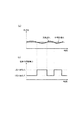
Therefore, even if there is a time-series change in the actual gear ratio with respect to the target gear ratio as shown in FIG. 11 (switching between positive and negative of the gear ratio deviation), the initial transient target driving force is maintained while the gear ratio deviation is small. As shown in FIG. 12, the corrected transient target driving force is settled in the vicinity of the driving force corresponding to the G point, and the transient target driving force described above with respect to FIG. 17 is between the G point equivalent value and the I point equivalent value. There is no problem of discontinuity.
ちなみに、上記のような変速比偏差が小さな定常運転からアクセルペダルの踏み込みにより加速した踏み込み加速時の作用を、図14および図15に基づき以下に説明する。
図15の瞬時t1における踏み込みにより初期過渡目標駆動力が図14の矢Kで示すように増大すると、目標変速比も図15(a)に示すように急増して、これと実変速比との偏差が正値を増大される結果、図14にHで例示する初期過渡目標駆動力および理想変速速度の組み合わせ点における初期過渡目標駆動力がI点相当値へと修正され、過渡目標駆動力と定められる。
Incidentally, the operation at the time of depressing acceleration that is accelerated by depressing the accelerator pedal from the steady operation with a small speed ratio deviation as described above will be described below with reference to FIGS.
When the initial transient target driving force increases as shown by the arrow K in FIG. 14 due to the depression at the instant t1 in FIG. 15, the target gear ratio also increases rapidly as shown in FIG. As a result of the deviation being increased to a positive value, the initial transient target driving force at the combination point of the initial transient target driving force and the ideal shift speed exemplified by H in FIG. 14 is corrected to the equivalent value of I point, and the transient target driving force and Determined.
しかし、初期過渡目標駆動力をH点相当値からI点相当値へと修正することは初期過渡目標駆動力を不変に保つことから、過渡目標駆動力は初期過渡目標駆動力と同じにされることを意味し、過渡目標駆動力を図15(b)に示すように、踏み込み時t1以後は踏み込み加速に見合った大きなものにして十分な駆動力を確保することができる。
そして踏み込み時t1以後、目標変速比への変速が図15(a)に示すように進行すると、バッテリ電力範囲PBmax〜PBminが図14に矢Lの方向へ二点鎖線で示すように変化することによる(モータトルク範囲Aも若干変化するが、図面の煩雑を避けるため図14では変化しないものとして示した)実現可能領域の変化で、上記のような過渡目標駆動力のもとでも変速速度0の点が実現可能領域内に位置して実変速比を目標変速比に保つことができる。
However, modifying the initial transient target driving force from the H point equivalent value to the I point equivalent value keeps the initial transient target driving force unchanged, so the transient target driving force is made the same as the initial transient target driving force. That is, as shown in FIG. 15 (b), the transient target driving force can be set to a large value corresponding to the depression acceleration after the depression t1 to ensure a sufficient driving force.
Then, after stepping on t1, when the shift to the target gear ratio proceeds as shown in FIG. 15 (a), the battery power range PBmax to PBmin changes in the direction of arrow L in FIG. (The motor torque range A also changes slightly, but is shown as not changing in FIG. 14 in order to avoid complication of the drawing.) The shift speed is 0 even under the transient target driving force as described above. Thus, the actual speed ratio can be maintained at the target speed ratio with the point in the feasible region.
また本実施例においては、図3におけるエンジン制御手段108が理想エンジン回転加速度ΔωEOPT(理想変速速度)が実現された時のハイブリッド変速機の回転系に係わる運動エネルギーの変化量を算出し、この運動エネルギー量を補償するような目標エンジントルクT* Eを求めて、運動エネルギーの変化量をエンジンに余分に与えるよう構成したから、
変速をエンジントルクがアシストすることとなり、過渡目標駆動力へのパワー不足を減ずることができ、より理想に近い駆動力と変速とをすることができる。
In this embodiment, the engine control means 108 in FIG. 3 calculates the amount of change in kinetic energy related to the rotational system of the hybrid transmission when the ideal engine rotational acceleration Δω EOPT (ideal speed) is realized. Since the target engine torque T * E that compensates for the amount of kinetic energy is obtained and the engine is given an extra amount of change in kinetic energy,
The engine torque assists the speed change, so that the power shortage to the transient target drive force can be reduced, and the drive force and speed change closer to the ideal can be achieved.
さらに本実施例においては、上記の目標エンジントルクT* Eをそのままエンジンコントローラ22へ供給せず、初期過渡目標駆動力T* o1から過渡目標駆動力T* oを差し引いて求めた駆動力差を目標エンジントルクT* Eに加算して、目標エンジントルクT* Eを当該駆動力差が補償されるよう補正してエンジンコントローラ22へ供給するから、
理想の駆動力に対する不足分をエンジントルクがアシストすることとなり、より理想に近い駆動力を出すことができる。
Further, in this embodiment, the target engine torque T * E is not supplied to the
The engine torque assists the shortage with respect to the ideal driving force, and a driving force closer to the ideal can be obtained.
1 変速機ケース
2 ラビニョオ型プラネタリギヤセット(差動装置)
3 複合電流2層モータ
ENG エンジン(主動力源)
4 第1のシングルピニオン遊星歯車組
5 第2のシングルピニオン遊星歯車組
6 カウンターシャフト
7 ディファレンシャルギヤ装置
8 駆動車輪
14 出力歯車
MG1 第1モータ/ジェネレータ
MG2 第2モータ/ジェネレータ
S1 サンギヤ
S2 サンギヤ
P1 ショートピニオン
P2 ロングピニオン
R1 リングギヤ
R2 リングギヤ
C キャリア
21 ハイブリッドコントローラ
22 エンジンコントローラ
23 モータコントローラ
24 インバータ
25 バッテリ
26 アクセル開度センサ
27 車速センサ
28 エンジン回転センサ
101 静的目標値演算手段
102 初期過渡目標駆動力演算手段
103 最低変速速度演算手段
104 理想変速速度演算手段
105 過渡目標値演算手段
106 エンジン回転サーボ制御手段
107 モータ制御手段
108 エンジン制御手段
1
3 Composite current 2-layer motor
ENG engine (main power source)
4 First single pinion planetary gear set 5 Second single pinion planetary gear set 6 Countershaft 7
14 Output gear
MG1 1st motor / generator
MG2 Second motor / generator
S1 sun gear
S2 sun gear
P1 short pinion
P2 Long pinion
R1 ring gear
R2 ring gear
C career
21 Hybrid controller
22 Engine controller
23 Motor controller
24 inverter
25 battery
26 Accelerator position sensor
27 Vehicle speed sensor
28 Engine rotation sensor
101 Static target value calculation means
102 Initial transient target driving force calculation means
103 Minimum shift speed calculation means
104 Ideal shift speed calculation means
105 Transient target value calculation means
106 Engine rotation servo control means
107 Motor control means
108 Engine control means
Claims (5)
運転状態に応じた前記駆動系への静的目標駆動力を演算する静的目標駆動力演算手段と、
該手段により求めた静的目標駆動力を基に、所定の時系列変化で駆動系への駆動力を該静的目標駆動力に向かわせるための初期過渡目標駆動力を演算する初期過渡目標駆動力演算手段と、
運転状態に応じた、前記主動力源および駆動系間の目標変速状態を演算する目標変速状態演算手段と、
この目標変速状態へ実変速状態を収束させる変速速度の最低値を規定した最低変速速度を演算する最低変速速度演算手段と、
前記モータ/ジェネレータ、該モータ/ジェネレータ用のバッテリおよび前記主動力源の現状で実現可能な、駆動力および変速速度の組み合わせに関した、これら駆動力および変速速度の二次元座標上における実現可能領域内で前記最低変速速度以上の変速速度を確保できるように前記初期過渡目標駆動力を修正して過渡目標駆動力を求めると共に、該修正後の過渡目標駆動力のもとで前記実現可能領域内に居続けるための変速速度可能範囲を求める過渡目標値演算手段と、
前記過渡目標駆動力を実現すると共に前記変速速度可能範囲内の変速速度で前記目標変速状態および実変速状態間の変速状態偏差を減らすよう主動力源およびモータ/ジェネレータを制御する過渡目標値実現手段とを具備することを特徴とするハイブリッド変速機の変速制御装置。 A two-degree-of-freedom differential device having a plurality of rotating members as rotating members arranged on the nomograph, and determining the rotating state of the other members when the rotating state of two members is determined among these rotating members The plurality of rotating members are respectively coupled with an input from a main power source, an output to a drive system, and a plurality of motors / generators, and the power from these motors / generators is adjusted to adjust the main power. In a hybrid transmission in which the speed ratio between the power source and the drive system can be changed steplessly,
A static target driving force calculating means for calculating a static target driving force to the driving system according to an operating state;
Based on the static target driving force obtained by the means, initial transient target driving for calculating the initial transient target driving force for directing the driving force to the driving system toward the static target driving force with a predetermined time-series change. Force calculating means;
Target shift state calculating means for calculating a target shift state between the main power source and the drive system according to the driving state;
A minimum shift speed calculating means for calculating a minimum shift speed defining a minimum value of the shift speed for converging the actual shift state to the target shift state;
Within the feasible region on the two-dimensional coordinates of the driving force and the shifting speed, regarding the combination of the driving force and the shifting speed that can be realized in the current state of the motor / generator, the battery for the motor / generator, and the main power source The initial transient target drive force is corrected to obtain a transient target drive force so that a shift speed equal to or greater than the minimum shift speed can be secured, and within the feasible region under the corrected transient target drive force. A transient target value calculating means for obtaining a speed changeable range for staying;
Transient target value realizing means for controlling the main power source and the motor / generator so as to realize the transient target driving force and reduce a shift state deviation between the target shift state and the actual shift state at a shift speed within the allowable shift speed range. A shift control apparatus for a hybrid transmission, comprising:
前記過渡目標値演算手段は、前記実現可能領域内で前記最低変速速度以上の変速速度が確保されることを条件に、前記初期過渡目標駆動力に最も近い駆動力を前記過渡目標駆動力とするものであることを特徴とするハイブリッド変速機の変速制御装置。 The shift control apparatus for a hybrid transmission according to claim 1,
The transient target value calculating means sets the driving force closest to the initial transient target driving force as the transient target driving force on the condition that a shift speed equal to or higher than the minimum shift speed is secured within the feasible region. What is claimed is: 1. A transmission control apparatus for a hybrid transmission, comprising:
前記過渡目標値演算手段は、前記最低変速速度が0近辺であり、運転状態の変化により変速速度が該最低変速速度の前後を往来するときに変速速度方向が切り替わる場合、一方の変速速度方向である時に求めた、前記初期過渡目標駆動力に最も近い第1の過渡目標駆動力と、他方の変速速度方向である時に求めた、前記初期過渡目標駆動力に最も近い第2の過渡目標駆動力とを比較し、第1の過渡目標駆動力が第2の過渡目標駆動力よりも前記初期過渡目標駆動力に近いなら、前記目標変速状態および実変速状態間の変速状態偏差が大きいほど前記過渡目標駆動力を第1の過渡目標駆動力に近い値とし、前記変速状態偏差が小さいほど前記過渡目標駆動力を第2の過渡目標駆動力に近い値とするものであることを特徴とするハイブリッド変速機の変速制御装置。 The shift control device for a hybrid transmission according to claim 1 or 2,
The transient target value calculation means is configured such that when the minimum shift speed is close to 0 and the shift speed direction is switched when the shift speed travels before and after the minimum shift speed due to a change in the driving state, The first transient target driving force closest to the initial transient target driving force obtained at a certain time and the second transient target driving force closest to the initial transient target driving force obtained when the speed is in the other shift speed direction. If the first transient target drive force is closer to the initial transient target drive force than the second transient target drive force, the greater the shift state deviation between the target shift state and the actual shift state, the greater the transient A hybrid in which the target driving force is a value close to the first transient target driving force, and the transient target driving force is a value closer to the second transient target driving force as the shift state deviation is smaller. Gear shifting Control device.
前記変速速度の理想値を規定した理想変速速度を演算する理想変速速度演算手段を設け、
この手段で求めた理想変速速度が実現された時の前記モータ/ジェネレータおよび主動力源を含む伝動機構の回転運動エネルギーの変化量に相当するエネルギー量を主動力源に余分に指令するよう構成したことを特徴とするハイブリッド変速機の変速制御装置。 The shift control device for a hybrid transmission according to any one of claims 1 to 3,
Providing an ideal shift speed calculating means for calculating an ideal shift speed defining an ideal value of the shift speed;
The main power source is further commanded with an energy amount corresponding to the amount of change in rotational kinetic energy of the transmission mechanism including the motor / generator and the main power source when the ideal speed change speed obtained by this means is realized. A shift control apparatus for a hybrid transmission.
前記初期過渡目標駆動力と過渡目標駆動力との差を補償するよう主動力源のトルクを補正するよう構成したことを特徴とするハイブリッド変速機の変速制御装置。
The shift control apparatus for a hybrid transmission according to any one of claims 1 to 3,
A shift control apparatus for a hybrid transmission configured to correct a torque of a main power source so as to compensate for a difference between the initial transient target drive force and the transient target drive force.
Priority Applications (1)
| Application Number | Priority Date | Filing Date | Title |
|---|---|---|---|
| JP2004301195A JP4111184B2 (en) | 2004-10-15 | 2004-10-15 | Shift control device for hybrid transmission |
Applications Claiming Priority (1)
| Application Number | Priority Date | Filing Date | Title |
|---|---|---|---|
| JP2004301195A JP4111184B2 (en) | 2004-10-15 | 2004-10-15 | Shift control device for hybrid transmission |
Publications (2)
| Publication Number | Publication Date |
|---|---|
| JP2006111155A JP2006111155A (en) | 2006-04-27 |
| JP4111184B2 true JP4111184B2 (en) | 2008-07-02 |
Family
ID=36380031
Family Applications (1)
| Application Number | Title | Priority Date | Filing Date |
|---|---|---|---|
| JP2004301195A Expired - Fee Related JP4111184B2 (en) | 2004-10-15 | 2004-10-15 | Shift control device for hybrid transmission |
Country Status (1)
| Country | Link |
|---|---|
| JP (1) | JP4111184B2 (en) |
Families Citing this family (3)
| Publication number | Priority date | Publication date | Assignee | Title |
|---|---|---|---|---|
| JP6183169B2 (en) * | 2013-11-14 | 2017-08-23 | 日産自動車株式会社 | Control device for hybrid vehicle |
| CN104828077B (en) * | 2014-07-29 | 2017-08-04 | 北汽福田汽车股份有限公司 | Hybrid vehicle and its torque distribution method |
| CN115009256A (en) * | 2022-06-01 | 2022-09-06 | 中国第一汽车股份有限公司 | Torque distribution method and device for hybrid vehicle |
-
2004
- 2004-10-15 JP JP2004301195A patent/JP4111184B2/en not_active Expired - Fee Related
Also Published As
| Publication number | Publication date |
|---|---|
| JP2006111155A (en) | 2006-04-27 |
Similar Documents
| Publication | Publication Date | Title |
|---|---|---|
| JP3700709B2 (en) | Shift control device for hybrid transmission | |
| EP1974971B1 (en) | Shift control device and method for hybrid vehicle | |
| JP3997955B2 (en) | Hybrid vehicle and control method thereof | |
| JP4267612B2 (en) | Drive device, automobile equipped with the same, and drive device control method | |
| KR20070029802A (en) | Power output apparatus, vehicle equipped with power output apparatus, and control method of power output apparatus | |
| JP2007022296A (en) | Hybrid car and control method thereof | |
| EP1426222A1 (en) | Hybrid transmission control system | |
| JP4258508B2 (en) | Hybrid vehicle and control method thereof | |
| JP4220961B2 (en) | Power output apparatus, automobile equipped with the same, control apparatus for power output apparatus, and control method for power output apparatus | |
| JP4466635B2 (en) | POWER OUTPUT DEVICE, ITS CONTROL METHOD, AND VEHICLE | |
| JP2010155512A (en) | Hybrid vehicle and method for controlling the same | |
| JP4259488B2 (en) | POWER OUTPUT DEVICE, VEHICLE HAVING THE SAME AND CONTROL METHOD THEREOF | |
| JP4462219B2 (en) | Hybrid vehicle and control method thereof | |
| JP4365354B2 (en) | Power output apparatus, automobile equipped with the same, and control method of power output apparatus | |
| JP3938001B2 (en) | Control method for hybrid transmission when abnormal | |
| JP4111184B2 (en) | Shift control device for hybrid transmission | |
| JP4371067B2 (en) | Power output apparatus, automobile equipped with the same, and control method of power output apparatus | |
| JP2008143426A (en) | Vehicle and control method | |
| JP2007239504A (en) | Automobile and its control method | |
| JP2005218221A (en) | Controller of hybrid vehicle | |
| JP2002281604A (en) | Self-propelled vehicle | |
| JP2010221896A (en) | Hybrid car and method for controlling the same | |
| JP3933081B2 (en) | Shift control device for hybrid transmission | |
| JP3885756B2 (en) | Shift control device for hybrid transmission | |
| JP2007137235A (en) | Vehicle and its control method |
Legal Events
| Date | Code | Title | Description |
|---|---|---|---|
| RD04 | Notification of resignation of power of attorney |
Free format text: JAPANESE INTERMEDIATE CODE: A7424 Effective date: 20060607 |
|
| A621 | Written request for application examination |
Free format text: JAPANESE INTERMEDIATE CODE: A621 Effective date: 20070829 |
|
| TRDD | Decision of grant or rejection written | ||
| A01 | Written decision to grant a patent or to grant a registration (utility model) |
Free format text: JAPANESE INTERMEDIATE CODE: A01 Effective date: 20080318 |
|
| A61 | First payment of annual fees (during grant procedure) |
Free format text: JAPANESE INTERMEDIATE CODE: A61 Effective date: 20080331 |
|
| R150 | Certificate of patent or registration of utility model |
Free format text: JAPANESE INTERMEDIATE CODE: R150 |
|
| FPAY | Renewal fee payment (event date is renewal date of database) |
Free format text: PAYMENT UNTIL: 20110418 Year of fee payment: 3 |
|
| FPAY | Renewal fee payment (event date is renewal date of database) |
Free format text: PAYMENT UNTIL: 20120418 Year of fee payment: 4 |
|
| FPAY | Renewal fee payment (event date is renewal date of database) |
Free format text: PAYMENT UNTIL: 20130418 Year of fee payment: 5 |
|
| FPAY | Renewal fee payment (event date is renewal date of database) |
Free format text: PAYMENT UNTIL: 20130418 Year of fee payment: 5 |
|
| FPAY | Renewal fee payment (event date is renewal date of database) |
Free format text: PAYMENT UNTIL: 20140418 Year of fee payment: 6 |
|
| LAPS | Cancellation because of no payment of annual fees |