JP4110659B2 - Hot water mixing valve - Google Patents
Hot water mixing valve Download PDFInfo
- Publication number
- JP4110659B2 JP4110659B2 JP06547999A JP6547999A JP4110659B2 JP 4110659 B2 JP4110659 B2 JP 4110659B2 JP 06547999 A JP06547999 A JP 06547999A JP 6547999 A JP6547999 A JP 6547999A JP 4110659 B2 JP4110659 B2 JP 4110659B2
- Authority
- JP
- Japan
- Prior art keywords
- water
- hot
- hot water
- mixing valve
- valve
- Prior art date
- Legal status (The legal status is an assumption and is not a legal conclusion. Google has not performed a legal analysis and makes no representation as to the accuracy of the status listed.)
- Expired - Fee Related
Links
Images


Description
【0001】
【発明の属する技術分野】
この発明は、サーモスタット式湯水混合水栓等に用いられる湯水混合弁の構造に関する。
【0002】
【従来の技術】
サーモスタット湯水混合栓の一例を図2と図3に示す。湯水はそれぞれの配管から逆止弁1、2を通過し、サーモスタットユニット3へと導かれる。サーモスタットユニット3に流入した湯水は適当な比率で混合され、適当な温度の混合水がサーモスタットユニット3より流出する。
【0003】
サーモスタットユニット3から流出した混合水は連結管4内を通り、開閉・流量調整ユニット5に流入する。開閉・流量調整ユニット5で適当な流量に調節され、カラン6から吐水される。
【0004】
従来のサーモスタット湯水混合弁の例を図10に示す。図10において、主な構成は、感温コイルばね10、バイアスばね11、弁体12、湯側シート部13、水側シート部14から成る。弁体12は両端にシート部があるスプール弁で、湯側シート13と水側シート14の間に配設され、感温コイルばね10とバイアスばね11の釣合いによってその位置が決定される。湯側シート13とスプール弁の隙間をとおり湯がスプール弁の外から内方向へ流れ、水側シート14とスプール弁の隙間をとおり水がスプール弁の外から内方向へ流れ、感温コイルばね10は通水路の下流側に位置し常に湯水の混合水の温度を感知できる位置にある。スプール弁一次側に臨む湯通水路17と水通水路18の間はOリング19でシールされている。バイアスばね11の荷重は、温度調節ハンドル15の回転に連動するネジ16を介することでによって適当な値に調節できる。
【0005】
以上のサーモスタットユニットの構成において、今、適当な混合水温度、適当なバイアスばね荷重、適当な弁の位置によって安定した通水温度が保たれているとする。この状態から、湯または水の温度変化や、湯または水の圧力変化等の変化が生じた場合、瞬間的に混合水温度の変化が生じるが、感温コイルばね10は感知温度の変化によってその荷重に変化が生じ、その結果、バイアスばね11との釣合い上、弁体12の位置にも変化が生じ、当初の混合水の温度変化が小さくなる方向に補正される。そのため使用者は、不意に、何らかの原因で、湯または水の圧力変化等が生じた場合でも快適にシャワーを浴びることができる。
【0006】
【発明が解決しようとする課題】
以上の構成で見た通り、サーモスタット湯水混合弁では、湯水の温度や圧力に変化が生じた時、湯水の混合比を決定する弁が、湯側シートと水側シートの間で位置を変えることで、湯水の混合比、すなわち吐水温度の変化を小さく押さえる。
【0007】
しかし、実際のサーモスタット湯水混合弁では、例えば、水圧が湯圧より高い状態から、湯圧が水圧より高い状態への変化があった場合、上記の混合弁の移動が十分に行なわれず、吐水温度の変化が大きくなり、使用者に不快感を与えることがある。
【0008】
このため一般には、混合弁の外径を拡大し、弁ストロークを小さくすることで温度調整性能の向上が図られる。これは、弁ストロークを小さくすることで、圧力変化時等の弁の必要移動量を減らすことができ、感温素子の駆動量に関する要求性能を軽減できるため効果がある。
【0009】
しかし、混合弁と湯側シートまたは水側シートの隙間を流れる通水断面積を確保するために混合弁の外径を大きくする必要がある。そのため、この方法では一般にサーモスタットユニットの外径が大きくなってしまう。また、混合弁の外径の拡大にともない、スプール弁一次側に臨む湯通水路と水通水路の間のシールを行なうOリングも拡大することとなり、その結果、該Oリングの摺動抵抗の増加によりスプール弁の移動抵抗も増加してしまう。スプール弁の移動抵抗の増加に対応するため、より高荷重、すなわち大型で高コスト、の感温素子を用いる必要がある。
【0010】
更に、上記の弁ストロークを小さくすることに関しては製造上の問題が生じてしまう。すなわち、一般に湯水混合水栓に用いられるサーモスタットにおいては、上記弁ストロークは1mm以下である。弁ストロークを小さくし、例えば0.5mmにした場合、製造上の寸法ばらつきにより実際は0.5±0.1mm程度となってしまい、0.4〜0.6mmまでの幅を持つことになる。この幅は水栓の圧力損失や温度調整性能のばらつきに大きな影響を与える。つまり、弁ストロークを小さくすることにより圧力損失や温度調整性能のばらつきは大きくなる。
【0011】
また、特に高流量で吐水中に前記混合弁が振動を起こし、吐水中に不快な音を発生することがあった。混合弁は、バイアスばねと感温コイルばねで釣り合い系を構成している。これらの釣合い系が、混合水の流れの中で発生した渦の周期と共振を起こし、振動が継続すると考えられる。
【0012】
本発明は、以上の問題点を鑑み、コンパクトで温度調整性能に優れ、高流量時でも混合弁の振動が起こりにくいサーモスタット湯水混合弁を提供することを目的とする。
【0013】
【課題を解決するための手段】
湯通水路、水通水路、混合水通水路、湯側シート部、水側シート部、前記湯側シート部、水側シート部間の位置に応じ、前記湯通水路、水通水路より供給される湯水の混合比を決定するスプール状の混合弁、湯水混合水の温度に依存し前記混合弁を駆動する感温駆動素子より成り、前記湯通水路、水通水路、混合水通水路の一部を構成するユニット本体を、前記スプール状の混合弁の内周部に配設し、前記湯通水路、水通水路は前記スプール状の混合弁の内周部から外周部へ通じ、前記スプール状の混合弁外周部において混合水通水路と連通して構成する。
【0014】
この発明のサーモスタット湯水混合弁によれば、コンパクトさと良好な温度調整性能を同時に満足することができる。
【0015】
【発明の実施の形態】
本発明において、スプール状の混合弁一次側に臨む湯通水路と水通水路のシール部材として、従来のOリングではなく、樹脂製等のC輪状リングを用いることで、Oリングに比べ摺動抵抗を小さく押さえられスプール弁の移動抵抗も低下できる。スプール弁の移動抵抗が低下できるため、より低荷重、すなわち小型で低コスト、の感温素子を用いることができる。
【0016】
また、前記湯側シート部、水側シートのうち少なくとも一方がユニット本体と別体であり、前記湯側シート部と水側シートの距離が組立て時に微調整可能とすることで、弁ストロークのばらつきを小さくすることができ、圧力損失や温度調整性能のばらつきも小さくできる。
【0017】
更に、前記感温駆動素子と前記バイアスの位置関係を同軸上に配置しないことで、スプール弁は前記軸と平行ではなく、僅かに角度を持つことになり、スプール弁の前記湯側シート部から水側シートの間の位置において、前記湯側シート部または水側シートに斜めに僅かな角度を持って接触していることが多くなりスプール弁の自由度が減る。このため、吐水中のスプール弁の振動を押さえることができる。
【0018】
また、前記スプール弁が、形状記憶合金製のコイルばねとバイアスばねにより駆動され、前記バイアスばねは、温度調節のハンドルとネジを介して連結されており、前記温度調節のハンドルの回転によって荷重設定が可能にしておけば、ワックスエレメンやバイメタル等の他の感温素子を用いた場合に比べ、湯水混合弁を軽量コンパクトにできる。
【0019】
【実施例】
図1に、サーモスタット湯水混合弁を内蔵する湯水混合水栓の使用状況の一例を示す。図2に、図1の湯水混合水栓部分の正面図を、図3に側面図を示す。第2図において、湯水はそれぞれの配管から逆止弁1,2を通過し、サーモスタットユニット3へと導かれる。サーモスタットユニット3に流入した湯水は適当な比率で混合され、適当な温度の混合水がサーモスタットユニット3より流出する。サーモスタットユニット3から流出した混合水は連結管4内を通り、開閉・流量調整ユニット5に流入する。開閉・流量調整ユニット5で適当な流量に調節された混合水はカラン6から吐水される。
【0020】
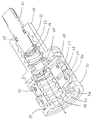
図4に本発明のサーモスタット湯水混合弁ユニットの実施例の断面付き斜視図を示す。図5に別の部分での断面を含む斜視図を示す。図6に同分解斜視図を示す。図4、図5において、ユニットの要部は、湯通水路35、水通水路34、混合水通水路36の一部を構成するユニット本体31、湯側シート部27と水側シート部37間をストローク可能で2部品26,29で構成されるスプール弁29、スプール弁29の上下に位置するバイアスばね24と形状記憶合金コイル28、前記バイアスばね24をガイドしネジ部を有しその回転によって軸方向に移動可能なばねガイド22、温度調節ハンドルの回転を前記ばねガイド22に伝えるスピンドル21から構成される。また、前記バイアスばね24と形状記憶合金コイル28は同軸上に配置されておらず若干の偏芯がある。
【0021】
温度調節ハンドルを回転は、スピンドル21を介してばねガイド22の軸方向の移動に変換され、バイアスばね24の荷重が可変、設定される。
【0022】
また、前記湯側シート部27はユニット本体31と別体でありネジで組み付ける構造となっており、組立て時に、前記スプール弁29と水側シート37の距離が規定値になるよう調整する。隙間ゲージを使用するか、前記湯側シート部27を一度最後まで締込み規定角度だけ戻すことで管理する。
【0023】
スプール弁29一次側に臨む湯通水路35と水通水路34のシール部材として、樹脂製のC輪状リング30を用いている。ユニット本体への組み込みは弾性変形させC輪を広げながら組み付ける。該リング30は、組み立てた状態で弾性力でスプール弁29内周部と接触するようになっている。
【0024】
通水の流れについて説明する。給水管、給湯管から流入した水、湯はそれぞれユニット本体内に形成された水通水路34、湯通水路35を通り、水側シート37、湯側シート27とスプール弁29の間に形成された隙間の比率に応じ適当な分量がスプール弁29外周部へ流れ混合される。混合水はユニット本体31の上側を経由し混合水通水路36を通ってサーモスタットユニットから流出する。この時、混合水は、混合水通水路36内に位置する形状記憶合金コイル28に接する形で通過する。
【0025】
次に作動原理について説明する。以上の構成において、今、適当な混合水温度、適当なバイアスばね24荷重、適当なスプール弁29の位置によって安定した通水温度が保たれているとする。この状態から、湯または水の温度変化や、湯または水の圧力変化等の変化が生じた場合、瞬間的に混合水温度の変化が生じるが、形状記憶合金コイル28は感知温度の変化によって荷重に変化が生じ、その結果、バイアスばね24との釣合い上、スプール弁29の位置にも変化が生じ、当初の混合水の温度変化が小さくなる方向に補正される。そのため使用者は、不意に、何らかの原因で、湯または水の圧力変化等が生じた場合でも快適にシャワーを浴びることができる。
【0026】
一般にサーモスタット湯水混合弁においては、混合弁、この場合スプール弁、の外径を拡大し、弁ストロークを小さくすることで温度調整性能の向上が図られる。弁ストロークを小さくすることで、圧力変化時等のスプール弁の必要移動量を減らすことができ、形状記憶合金コイルの駆動量に関する要求性能を軽減でき、同じ形状記憶合金コイルの仕様であれば弁ストロークが小さいほど一般に温度調整性能が優れるためである。
【0027】
しかし、スプール弁と湯側シートまたは水側シートの隙間を流れる通水断面積を確保するために混合弁の外径を大きくする必要がある。そのため、従来のサーモスタット湯水混合弁の構成において、この方法をとるとサーモスタットユニットの外径が大きくなってしまう。
【0028】
一方、本発明のサーモスタット湯水混合弁では、湯通水路35、水通水路34、混合水通水路36をスプール弁29の内周側に配設したため、必然的にスプール弁29の径は大きくなる。同時に、スプール弁29外周部は水通水路34のみであるため、スプール弁外周部に水通水路40と湯通水路41がある従来のサーモスタット湯水混合弁に比べ、スプール弁29の径は大きくできる。すなわちスプール弁29のストロークを小さくでき、良好な温度調整性能が得られる。この説明の概念図を図7、図8に示す。図7は本発明の通水路構成の概念図、図8は従来のサーモスタット湯水混合弁の通水路構成の概念図である。
【0029】
本発明において、スプール状29の一次側に臨む湯通水路35と水通水路34のシール部材として、従来のOリングではなく、樹脂製等のC輪状リング30を用いることで、Oリングに比べ摺動抵抗を小さく押さえられスプール弁29の移動抵抗も低下できる。スプール弁29の移動抵抗が低下できるため、より低荷重、すなわち小型で低コストの形状記憶合金コイル28を用いることができる。あるいは、より良好な温度調整性能が得られる。
【0030】
なお、湯水混合水栓等に用いられるサーモスタット湯水混合弁においては、前記スプール弁29一次側に臨む湯通水路35と水通水路34のシール部分は、一般に、必ずしも水密状である必要はなく、少量の湯通水路35と水通水路34間の漏れは許容される。このため上記のC輪状リング30をシール部材として使用することが可能となる。
【0031】
前記Cリング30によるシール構造は従来のサーモスタット湯水混合弁にも適用できる。
【0032】
また、本発明では、前記湯側シート部27がユニット本体31と別体でありネジで組み付ける構造となっており、組立て時に、前記スプール弁29と水側シート37の距離が一定になるよう微調整可能とすることができる。隙間ゲージを使用するか、前記湯側シート部を一度最後まで締込み規定角度だけ戻すことで管理できる。Oリング32はシールの目的だけでなく前記別体の湯側シート部27を固定させる目的もある。
【0033】
このように、前記湯側シート部27、水側シート部37のうち少なくとも一方がユニット本体31と別体であり、前記湯側シート部27と水側シート部37の距離が組立て時に微調整可能とすることで、弁ストロークのばらつきを小さくすることができ、圧力損失や温度調整性能のばらつきも小さくできる。
【0034】
前記バイアスばね24と形状記憶合金コイル28は同軸上に配置されておらず若干の偏芯がある。このように、前記形状記憶合金コイル28と前記バイアスばね24の位置関係を同軸上に配置しないことで、前記スプール弁29は前記軸と平行ではなく、僅かに角度を持つことになり、前記スプール弁29の前記湯側シート部27から水側シート部37の間の位置において、前記湯側シート部27または水側シート部37に斜めに僅かな角度を持って接触していることが多くなり、スプール弁の運動の自由度が減る。このため、吐水中のスプール弁の振動を押さえる効果がある。この説明の概念図を図9に示す。
【0035】
感温駆動素子とバイアスの位置関係を同軸上に配置しない構造は従来のサーモスタット湯水混合弁にも適用できる。
【0036】
【発明の効果】
湯通水路、水通水路、混合水通水路、湯側シート部、水側シート部、前記湯側シート部、水側シート部間の位置に応じ、前記湯通水路、水通水路より供給される湯水の混合比を決定するスプール状の混合弁、湯水混合水の温度に依存し前記混合弁を駆動する感温駆動素子より成り、前記湯通水路、水通水路、混合水通水路の一部を構成するユニット本体を、前記スプール状の混合弁の内周部に配設し、前記湯通水路、水通水路は前記スプール状の混合弁の内周部から外周部へ通じ、前記スプール状の混合弁外周部において混合水通水路と連通して構成されるため、従来と同様のユニット外径寸法でも、スプール状の混合弁の外径を大きく、弁ストロークを小さくできることで、良好な温度調整性能が得られる。
【図面の簡単な説明】
【図1】サーモスタット湯水混合弁を内蔵する湯水混合水栓の使用状況の一例を示す。
【図2】サーモスタット湯水混合栓の一例を示す正面図。
【図3】サーモスタット湯水混合栓の一例を示す側面図。
【図4】本発明によるサーモスタット湯水混合弁の実施例の断面付き斜視図である。
【図5】同別の断面での断面付き斜視図である。
【図6】同分解斜視図である。
【図7】本発明のサーモスタット湯水混合弁の通水路構成の概念図である。
【図8】従来のサーモスタット湯水混合弁の通水路構成の概念図である。
【図9】本発明のサーモスタット湯水混合弁の感温素子とバイアスばねの位置関係についての概念図である
【図10】従来のサーモスタット湯水混合弁の縦断面図である。
【符号の説明】
35…湯通水路
34…水通水路
36…混合水通水路
27…湯側シート部
37…水側シート部
29…混合弁
28…感温駆動素子
30…C輪状リング
24…バイアスばね[0001]
BACKGROUND OF THE INVENTION
The present invention relates to a structure of a hot and cold water mixing valve used for a thermostat type hot and cold water mixing faucet and the like.
[0002]
[Prior art]
An example of a thermostat hot and cold water mixing tap is shown in FIGS. Hot water passes through the check valves 1 and 2 from the respective pipes and is led to the
[0003]
The mixed water flowing out of the
[0004]
An example of a conventional thermostat hot / cold water mixing valve is shown in FIG. In FIG. 10, the main configuration includes a temperature-sensitive coil spring 10, a
[0005]
In the above thermostat unit configuration, it is assumed that a stable water flow temperature is maintained by an appropriate mixed water temperature, an appropriate bias spring load, and an appropriate valve position. If a change in temperature of hot water or water or a change in pressure of hot water or water occurs from this state, the temperature of the mixed water instantaneously changes. A change occurs in the load, and as a result, a change also occurs in the position of the
[0006]
[Problems to be solved by the invention]
As seen in the above configuration, in the thermostat hot water mixing valve, when the temperature or pressure of hot water changes, the valve that determines the mixing ratio of hot water changes the position between the hot water side sheet and the water side sheet. Thus, the mixing ratio of hot and cold water, that is, the change in water discharge temperature is kept small.
[0007]
However, in an actual thermostat hot / cold water mixing valve, for example, when there is a change from a state in which the water pressure is higher than the hot water pressure to a state in which the hot water pressure is higher than the water pressure, the above-described mixing valve does not move sufficiently, and the water discharge temperature May increase discomfort to the user.
[0008]
Therefore, generally, the temperature adjustment performance can be improved by enlarging the outer diameter of the mixing valve and reducing the valve stroke. This is effective because the required amount of movement of the valve at the time of a pressure change or the like can be reduced by reducing the valve stroke, and the required performance related to the driving amount of the temperature sensing element can be reduced.
[0009]
However, it is necessary to increase the outer diameter of the mixing valve in order to ensure a water flow cross-sectional area flowing through the gap between the mixing valve and the hot water side sheet or the water side sheet. Therefore, this method generally increases the outer diameter of the thermostat unit. In addition, as the outer diameter of the mixing valve increases, the O-ring that seals between the hot water passage and the water passage facing the primary side of the spool valve also increases, and as a result, the sliding resistance of the O-ring increases. The movement resistance of the spool valve increases due to the increase. In order to cope with an increase in the movement resistance of the spool valve, it is necessary to use a temperature sensitive element having a higher load, that is, a large size and a high cost.
[0010]
Furthermore, manufacturing problems are associated with reducing the valve stroke. That is, in the thermostat generally used for a hot and cold water mixing faucet, the valve stroke is 1 mm or less. When the valve stroke is reduced to, for example, 0.5 mm, the actual size is about 0.5 ± 0.1 mm due to dimensional variations in manufacturing, and the width is 0.4 to 0.6 mm. This width has a great influence on the pressure loss of the faucet and the variation in temperature control performance. That is, variation in pressure loss and temperature adjustment performance increases by reducing the valve stroke.
[0011]
In addition, the mixing valve may vibrate during discharge at a particularly high flow rate, and an unpleasant sound may be generated during discharge. The mixing valve forms a balance system with a bias spring and a temperature-sensitive coil spring. It is considered that these balance systems resonate with the period of the vortex generated in the mixed water flow, and the vibration continues.
[0012]
In view of the above problems, an object of the present invention is to provide a thermostatic hot / cold water mixing valve that is compact, excellent in temperature adjustment performance, and less susceptible to vibration of the mixing valve even at a high flow rate.
[0013]
[Means for Solving the Problems]
Depending on the position between the hot water channel, the water channel, the mixed water channel, the hot water side sheet part, the water side sheet part, the hot water side sheet part, the water side sheet part, it is supplied from the hot water channel, the water water channel. A spool-shaped mixing valve that determines the mixing ratio of hot and cold water, and a temperature-sensitive driving element that drives the mixing valve depending on the temperature of the hot and cold water mixture, and includes one of the hot water passage, the water passage, and the mixed water passage. A unit main body constituting a portion is disposed on an inner peripheral portion of the spool-like mixing valve, and the hot water passage and the water passage are communicated from an inner peripheral portion to an outer peripheral portion of the spool-like mixing valve, and the spool The outer periphery of the mixing valve is configured to communicate with the mixed water passage.
[0014]
According to the thermostat hot and cold water mixing valve of the present invention, it is possible to satisfy both compactness and good temperature adjustment performance at the same time.
[0015]
DETAILED DESCRIPTION OF THE INVENTION
In the present invention, as a sealing member for the hot water passage and the water passage that faces the primary side of the spool-shaped mixing valve, instead of the conventional O-ring, a C ring-shaped ring made of resin or the like is used, so that it slides compared to the O-ring The resistance can be kept small, and the movement resistance of the spool valve can be reduced. Since the movement resistance of the spool valve can be reduced, a temperature sensor with a lower load, that is, a small size and a low cost can be used.
[0016]
Further, at least one of the hot water side seat portion and the water side seat is separate from the unit main body, and the distance between the hot water side seat portion and the water side seat can be finely adjusted at the time of assembly, thereby varying the valve stroke. , And variations in pressure loss and temperature adjustment performance can be reduced.
[0017]
Furthermore, the positional relationship between the temperature-sensitive drive element and the bias is not arranged coaxially, so that the spool valve is not parallel to the shaft but has a slight angle, and the spool valve has a slight angle from the hot water side seat portion. At a position between the water side seats, the hot water side seat portion or the water side seat is often in contact with an oblique angle, and the degree of freedom of the spool valve is reduced. For this reason, it is possible to suppress the vibration of the spool valve during water discharge.
[0018]
The spool valve is driven by a shape memory alloy coil spring and a bias spring, and the bias spring is connected to the temperature adjustment handle via a screw, and the load is set by rotating the temperature adjustment handle. If this is possible, the hot and cold water mixing valve can be made lighter and more compact than when other temperature sensitive elements such as wax elements and bimetals are used.
[0019]
【Example】
In FIG. 1, an example of the usage condition of the hot / cold water faucet incorporating a thermostat hot / cold water mixing valve is shown. 2 is a front view of the hot and cold water mixing faucet portion of FIG. 1, and FIG. 3 is a side view thereof. In FIG. 2, hot water passes through check valves 1 and 2 from each pipe and is led to the
[0020]
FIG. 4 shows a perspective view with a cross section of an embodiment of a thermostat hot / cold water mixing valve unit of the present invention. FIG. 5 shows a perspective view including a cross section of another portion. FIG. 6 shows an exploded perspective view of the same. 4 and 5, the main part of the unit is a unit
[0021]
The rotation of the temperature adjustment handle is converted into an axial movement of the
[0022]
Further, the hot
[0023]
As a sealing member for the
[0024]
The flow of water will be described. Water and hot water flowing in from the water supply pipe and hot water supply pipe are formed between the
[0025]
Next, the operation principle will be described. In the above configuration, it is assumed that a stable water flow temperature is maintained by an appropriate mixed water temperature, an
[0026]
In general, in a thermostatic hot / cold water mixing valve, the outer diameter of the mixing valve, in this case, the spool valve, is enlarged, and the temperature adjustment performance is improved by reducing the valve stroke. By reducing the valve stroke, the required amount of movement of the spool valve during pressure changes can be reduced, and the required performance related to the drive amount of the shape memory alloy coil can be reduced. This is because the smaller the stroke, the better the temperature adjustment performance.
[0027]
However, it is necessary to increase the outer diameter of the mixing valve in order to ensure a cross-sectional area of water flowing through the gap between the spool valve and the hot water side sheet or the water side sheet. Therefore, if this method is used in the configuration of the conventional thermostat hot / cold water mixing valve, the outer diameter of the thermostat unit is increased.
[0028]
On the other hand, in the thermostat hot / cold water mixing valve of the present invention, since the
[0029]
In the present invention, as a sealing member for the
[0030]
In the thermostat hot / cold water mixing valve used for the hot / cold water faucet or the like, the seal portion of the
[0031]
The sealing structure by the C-
[0032]
Further, in the present invention, the hot water
[0033]
Thus, at least one of the hot water
[0034]
The
[0035]
A structure in which the positional relationship between the temperature-sensitive driving element and the bias is not arranged coaxially can also be applied to a conventional thermostat hot / cold mixing valve.
[0036]
【The invention's effect】
Depending on the position between the hot water channel, the water channel, the mixed water channel, the hot water side sheet part, the water side sheet part, the hot water side sheet part, the water side sheet part, it is supplied from the hot water channel, the water water channel. A spool-shaped mixing valve that determines the mixing ratio of hot and cold water, and a temperature-sensitive driving element that drives the mixing valve depending on the temperature of the hot and cold water mixture, and includes one of the hot water passage, the water passage, and the mixed water passage. A unit main body constituting a portion is disposed on an inner peripheral portion of the spool-like mixing valve, and the hot water passage and the water passage are communicated from an inner peripheral portion to an outer peripheral portion of the spool-like mixing valve, and the spool Since the outer periphery of the mixing valve communicates with the mixed water passage, the outer diameter of the spool-shaped mixing valve can be increased and the valve stroke can be reduced even with the same unit outer diameter as in the past. Temperature adjustment performance is obtained.
[Brief description of the drawings]
FIG. 1 shows an example of a usage situation of a hot and cold water mixing faucet incorporating a thermostatic hot and cold water mixing valve.
FIG. 2 is a front view showing an example of a thermostat hot / cold mixing tap.
FIG. 3 is a side view showing an example of a thermostat hot / cold mixing tap.
FIG. 4 is a perspective view with a cross section of an embodiment of a thermostatic hot and cold water mixing valve according to the present invention.
FIG. 5 is a perspective view with a cross section in another cross section.
FIG. 6 is an exploded perspective view of the same.
FIG. 7 is a conceptual diagram of a water passage configuration of the thermostat hot / cold water mixing valve of the present invention.
FIG. 8 is a conceptual diagram of a water passage configuration of a conventional thermostat hot / cold water mixing valve.
FIG. 9 is a conceptual diagram of the positional relationship between the temperature sensing element and the bias spring of the thermostat hot / cold mixing valve of the present invention. FIG. 10 is a longitudinal sectional view of a conventional thermostat hot / cold water mixing valve.
[Explanation of symbols]
35 ...
Claims (1)
Priority Applications (1)
| Application Number | Priority Date | Filing Date | Title |
|---|---|---|---|
| JP06547999A JP4110659B2 (en) | 1999-03-11 | 1999-03-11 | Hot water mixing valve |
Applications Claiming Priority (1)
| Application Number | Priority Date | Filing Date | Title |
|---|---|---|---|
| JP06547999A JP4110659B2 (en) | 1999-03-11 | 1999-03-11 | Hot water mixing valve |
Related Child Applications (1)
| Application Number | Title | Priority Date | Filing Date |
|---|---|---|---|
| JP2008005484A Division JP2008101783A (en) | 2008-01-15 | 2008-01-15 | Hot-water and water mixing valve |
Publications (3)
| Publication Number | Publication Date |
|---|---|
| JP2000266227A JP2000266227A (en) | 2000-09-26 |
| JP2000266227A5 JP2000266227A5 (en) | 2006-10-12 |
| JP4110659B2 true JP4110659B2 (en) | 2008-07-02 |
Family
ID=13288286
Family Applications (1)
| Application Number | Title | Priority Date | Filing Date |
|---|---|---|---|
| JP06547999A Expired - Fee Related JP4110659B2 (en) | 1999-03-11 | 1999-03-11 | Hot water mixing valve |
Country Status (1)
| Country | Link |
|---|---|
| JP (1) | JP4110659B2 (en) |
Families Citing this family (1)
| Publication number | Priority date | Publication date | Assignee | Title |
|---|---|---|---|---|
| JP2002106732A (en) * | 2000-09-27 | 2002-04-10 | San-Ei Faucet Mfg Co Ltd | Combination faucet |
-
1999
- 1999-03-11 JP JP06547999A patent/JP4110659B2/en not_active Expired - Fee Related
Also Published As
| Publication number | Publication date |
|---|---|
| JP2000266227A (en) | 2000-09-26 |
Similar Documents
| Publication | Publication Date | Title |
|---|---|---|
| RU2106559C1 (en) | Tap cock mixing valve | |
| JP4681945B2 (en) | Hot water tap | |
| JP4110659B2 (en) | Hot water mixing valve | |
| JP3018945B2 (en) | Hot water mixing equipment | |
| JP2006329304A (en) | Mixing faucet of automatic temperature control type | |
| JP4042013B2 (en) | Hot water mixing valve | |
| JP4566657B2 (en) | Hot water mixing valve | |
| WO2017110213A1 (en) | Fluid control valve device for hot water combination faucet | |
| JP3882192B2 (en) | Hot water mixing apparatus and hot water mixing faucet provided with the same | |
| JP4591860B2 (en) | Hot water tap | |
| JP3584973B2 (en) | Hot water mixing valve | |
| JP2008101783A (en) | Hot-water and water mixing valve | |
| JP2001254868A (en) | Water and hot water mixing device | |
| JP2006057761A5 (en) | ||
| JP2000266232A5 (en) | ||
| JP3310149B2 (en) | Hot water mixer tap | |
| JPH0314608Y2 (en) | ||
| JPH11257528A (en) | Control mechanism for hot and cold water combination device | |
| JP3360989B2 (en) | Hot water mixer tap | |
| JP3882194B1 (en) | Hot water mixing apparatus and hot water mixing faucet provided with the same | |
| JPH0842744A (en) | Hot water and water mixing device | |
| JP5006539B2 (en) | Hot water tap | |
| JP2005249059A (en) | Combination faucet | |
| JP2004251383A (en) | Combination faucet | |
| JPS6116465Y2 (en) |
Legal Events
| Date | Code | Title | Description |
|---|---|---|---|
| A621 | Written request for application examination |
Free format text: JAPANESE INTERMEDIATE CODE: A621 Effective date: 20060306 |
|
| A521 | Written amendment |
Free format text: JAPANESE INTERMEDIATE CODE: A523 Effective date: 20060829 |
|
| A977 | Report on retrieval |
Free format text: JAPANESE INTERMEDIATE CODE: A971007 Effective date: 20071127 |
|
| A131 | Notification of reasons for refusal |
Free format text: JAPANESE INTERMEDIATE CODE: A131 Effective date: 20071130 |
|
| A521 | Written amendment |
Free format text: JAPANESE INTERMEDIATE CODE: A523 Effective date: 20071221 |
|
| TRDD | Decision of grant or rejection written | ||
| A01 | Written decision to grant a patent or to grant a registration (utility model) |
Free format text: JAPANESE INTERMEDIATE CODE: A01 Effective date: 20080318 |
|
| A61 | First payment of annual fees (during grant procedure) |
Free format text: JAPANESE INTERMEDIATE CODE: A61 Effective date: 20080331 |
|
| R150 | Certificate of patent or registration of utility model |
Free format text: JAPANESE INTERMEDIATE CODE: R150 |
|
| FPAY | Renewal fee payment (event date is renewal date of database) |
Free format text: PAYMENT UNTIL: 20110418 Year of fee payment: 3 |
|
| FPAY | Renewal fee payment (event date is renewal date of database) |
Free format text: PAYMENT UNTIL: 20120418 Year of fee payment: 4 |
|
| FPAY | Renewal fee payment (event date is renewal date of database) |
Free format text: PAYMENT UNTIL: 20130418 Year of fee payment: 5 |
|
| FPAY | Renewal fee payment (event date is renewal date of database) |
Free format text: PAYMENT UNTIL: 20130418 Year of fee payment: 5 |
|
| FPAY | Renewal fee payment (event date is renewal date of database) |
Free format text: PAYMENT UNTIL: 20140418 Year of fee payment: 6 |
|
| LAPS | Cancellation because of no payment of annual fees |