JP4109261B2 - Hollow fan blades for gas turbine engines - Google Patents
Hollow fan blades for gas turbine engines Download PDFInfo
- Publication number
- JP4109261B2 JP4109261B2 JP2005017037A JP2005017037A JP4109261B2 JP 4109261 B2 JP4109261 B2 JP 4109261B2 JP 2005017037 A JP2005017037 A JP 2005017037A JP 2005017037 A JP2005017037 A JP 2005017037A JP 4109261 B2 JP4109261 B2 JP 4109261B2
- Authority
- JP
- Japan
- Prior art keywords
- ribs
- fan blade
- substrate
- hollow fan
- cavity
- Prior art date
- Legal status (The legal status is an assumption and is not a legal conclusion. Google has not performed a legal analysis and makes no representation as to the accuracy of the status listed.)
- Active
Links
Images


Classifications
-
- B—PERFORMING OPERATIONS; TRANSPORTING
- B23—MACHINE TOOLS; METAL-WORKING NOT OTHERWISE PROVIDED FOR
- B23P—METAL-WORKING NOT OTHERWISE PROVIDED FOR; COMBINED OPERATIONS; UNIVERSAL MACHINE TOOLS
- B23P15/00—Making specific metal objects by operations not covered by a single other subclass or a group in this subclass
- B23P15/04—Making specific metal objects by operations not covered by a single other subclass or a group in this subclass turbine or like blades from several pieces
-
- F—MECHANICAL ENGINEERING; LIGHTING; HEATING; WEAPONS; BLASTING
- F01—MACHINES OR ENGINES IN GENERAL; ENGINE PLANTS IN GENERAL; STEAM ENGINES
- F01D—NON-POSITIVE DISPLACEMENT MACHINES OR ENGINES, e.g. STEAM TURBINES
- F01D5/00—Blades; Blade-carrying members; Heating, heat-insulating, cooling or antivibration means on the blades or the members
- F01D5/12—Blades
- F01D5/14—Form or construction
- F01D5/147—Construction, i.e. structural features, e.g. of weight-saving hollow blades
-
- F—MECHANICAL ENGINEERING; LIGHTING; HEATING; WEAPONS; BLASTING
- F01—MACHINES OR ENGINES IN GENERAL; ENGINE PLANTS IN GENERAL; STEAM ENGINES
- F01D—NON-POSITIVE DISPLACEMENT MACHINES OR ENGINES, e.g. STEAM TURBINES
- F01D5/00—Blades; Blade-carrying members; Heating, heat-insulating, cooling or antivibration means on the blades or the members
- F01D5/12—Blades
- F01D5/14—Form or construction
- F01D5/18—Hollow blades, i.e. blades with cooling or heating channels or cavities; Heating, heat-insulating or cooling means on blades
-
- F—MECHANICAL ENGINEERING; LIGHTING; HEATING; WEAPONS; BLASTING
- F04—POSITIVE - DISPLACEMENT MACHINES FOR LIQUIDS; PUMPS FOR LIQUIDS OR ELASTIC FLUIDS
- F04D—NON-POSITIVE-DISPLACEMENT PUMPS
- F04D29/00—Details, component parts, or accessories
- F04D29/26—Rotors specially for elastic fluids
- F04D29/32—Rotors specially for elastic fluids for axial flow pumps
- F04D29/321—Rotors specially for elastic fluids for axial flow pumps for axial flow compressors
- F04D29/324—Blades
-
- F—MECHANICAL ENGINEERING; LIGHTING; HEATING; WEAPONS; BLASTING
- F05—INDEXING SCHEMES RELATING TO ENGINES OR PUMPS IN VARIOUS SUBCLASSES OF CLASSES F01-F04
- F05D—INDEXING SCHEME FOR ASPECTS RELATING TO NON-POSITIVE-DISPLACEMENT MACHINES OR ENGINES, GAS-TURBINES OR JET-PROPULSION PLANTS
- F05D2220/00—Application
- F05D2220/30—Application in turbines
- F05D2220/32—Application in turbines in gas turbines
- F05D2220/324—Application in turbines in gas turbines to drive unshrouded, low solidity propeller
-
- F—MECHANICAL ENGINEERING; LIGHTING; HEATING; WEAPONS; BLASTING
- F05—INDEXING SCHEMES RELATING TO ENGINES OR PUMPS IN VARIOUS SUBCLASSES OF CLASSES F01-F04
- F05D—INDEXING SCHEME FOR ASPECTS RELATING TO NON-POSITIVE-DISPLACEMENT MACHINES OR ENGINES, GAS-TURBINES OR JET-PROPULSION PLANTS
- F05D2220/00—Application
- F05D2220/30—Application in turbines
- F05D2220/36—Application in turbines specially adapted for the fan of turbofan engines
-
- F—MECHANICAL ENGINEERING; LIGHTING; HEATING; WEAPONS; BLASTING
- F05—INDEXING SCHEMES RELATING TO ENGINES OR PUMPS IN VARIOUS SUBCLASSES OF CLASSES F01-F04
- F05D—INDEXING SCHEME FOR ASPECTS RELATING TO NON-POSITIVE-DISPLACEMENT MACHINES OR ENGINES, GAS-TURBINES OR JET-PROPULSION PLANTS
- F05D2230/00—Manufacture
- F05D2230/10—Manufacture by removing material
-
- Y—GENERAL TAGGING OF NEW TECHNOLOGICAL DEVELOPMENTS; GENERAL TAGGING OF CROSS-SECTIONAL TECHNOLOGIES SPANNING OVER SEVERAL SECTIONS OF THE IPC; TECHNICAL SUBJECTS COVERED BY FORMER USPC CROSS-REFERENCE ART COLLECTIONS [XRACs] AND DIGESTS
- Y02—TECHNOLOGIES OR APPLICATIONS FOR MITIGATION OR ADAPTATION AGAINST CLIMATE CHANGE
- Y02T—CLIMATE CHANGE MITIGATION TECHNOLOGIES RELATED TO TRANSPORTATION
- Y02T50/00—Aeronautics or air transport
- Y02T50/60—Efficient propulsion technologies, e.g. for aircraft
-
- Y—GENERAL TAGGING OF NEW TECHNOLOGICAL DEVELOPMENTS; GENERAL TAGGING OF CROSS-SECTIONAL TECHNOLOGIES SPANNING OVER SEVERAL SECTIONS OF THE IPC; TECHNICAL SUBJECTS COVERED BY FORMER USPC CROSS-REFERENCE ART COLLECTIONS [XRACs] AND DIGESTS
- Y10—TECHNICAL SUBJECTS COVERED BY FORMER USPC
- Y10T—TECHNICAL SUBJECTS COVERED BY FORMER US CLASSIFICATION
- Y10T29/00—Metal working
- Y10T29/49—Method of mechanical manufacture
- Y10T29/49316—Impeller making
- Y10T29/49336—Blade making
- Y10T29/49339—Hollow blade
Abstract
Description
本発明は概してガスタービンエンジンに関し、さらに詳しくはガスタービンエンジン用の改良された中空ファンブレードに関する。 The present invention relates generally to gas turbine engines, and more particularly to improved hollow fan blades for gas turbine engines.
航空機用のターボファンエンジンのようなガスタービンエンジンは、ファンセクションと、コンプレッサーセクションと、燃焼セクションと、タービンセクションとを具備する。エンジンの軸線はその中心に配置されており、かつ上記セクションを貫通して前後方向に延在する。作動媒体ガス用の一次流路はエンジンの上記セクションを経て軸方向に延在する。作動媒体ガス用の二次流路は一次流路と平行にかつその半径方向外側に延在する。 A gas turbine engine, such as an aircraft turbofan engine, includes a fan section, a compressor section, a combustion section, and a turbine section. The engine axis is located at the center and extends through the section in the front-rear direction. The primary flow path for the working medium gas extends axially through the section of the engine. The secondary flow path for the working medium gas extends parallel to the primary flow path and radially outward.
上記ファンセクションはローターアセンブリおよびステータアセンブリを含む。ファンのローターアセンブリは、ローターディスクおよび半径方向に延在する複数のファンブレードを含む。ファンブレードは上記流路を経て延在すると共に作動媒体ガスと相互作用し、ファンブレードと作動媒体ガスとの間でエネルギーを伝達する。ステータアセンブリはファンケースを備え、これはファンブレードの先端に非常に接近した状態でローターアセンブリを取り囲む。 The fan section includes a rotor assembly and a stator assembly. The fan rotor assembly includes a rotor disk and a plurality of radially extending fan blades. The fan blade extends through the flow path and interacts with the working medium gas to transfer energy between the fan blade and the working medium gas. The stator assembly includes a fan case that surrounds the rotor assembly in close proximity to the tips of the fan blades.
運転中、ファンは作動媒体ガス、さらに詳しくは空気をエンジン内に引き込む。ファンは二次流路に沿って引き込まれた空気の圧力を上昇させ、これによって有効な推力を発生させる。一次流路に沿ってコンプレッサーセクション内に引き込まれた空気は圧縮される。この圧縮された空気は燃焼セクションへと送られ、そこで燃料がこの圧縮空気に加えられ、そして空気/燃料ミックスチャは燃焼させられる。燃焼生成物はタービンセクションへ排出される。タービンセクションエキストラクトはこの生成物によって作動し、ファンの駆動および空気圧縮を行う。ファンおよびコンプレッサーを駆動するのに必要とされない燃焼生成物のエネルギーは有効推力に寄与する。 During operation, the fan draws working medium gas, more specifically air, into the engine. The fan increases the pressure of the air drawn along the secondary flow path, thereby generating an effective thrust. Air drawn into the compressor section along the primary flow path is compressed. The compressed air is sent to the combustion section where fuel is added to the compressed air and the air / fuel mix is burned. The combustion products are discharged to the turbine section. The turbine section extract is driven by this product to drive the fan and compress the air. The combustion product energy that is not required to drive the fan and compressor contributes to the effective thrust.
重量軽減のために、いくつかのガスタービンエンジンにおいてファンブレードは中空である。各ファンブレードは二つの別個な単一半体を組み合わせて作られる。各半体は、重量を軽減し、その一方で構造的に堅固な内部形状を形成するため、機械加工によって削り出された複数のキャビティおよびリブを含む。これら半体は続いて中空ファンブレードを形成するために接合される。この中空ファンブレードには続いて極度の高温で成形処理が施される。この際に中空ファンブレードに翼形状およびジオメトリーが付与される。成形作業の間、二つの単一半体は、所望の形状となるまで高温状態でねじられかつ湾曲させられる。中空ファンブレード設計に固有のものは、翼形部の凸状および凹状側面における一対の「外皮」である。これら外皮は、接合(bonding)および成形作業中、非常に大きな圧縮荷重を受ける。高温下では、外皮はこの荷重に耐える強靭さを失い、ブレード中心に向かって内側に沈下する(sagging)かまたは垂れる(drooping)ことによって変形する。成形処理中のキャビティ圧潰を防止するためキャビティには高圧ガスが充填され、成形作業中、そのジオメトリーが維持される。 To reduce weight, the fan blades are hollow in some gas turbine engines. Each fan blade is made by combining two separate single halves. Each half includes a plurality of cavities and ribs machined out to reduce weight while forming a structurally rigid internal shape. These halves are subsequently joined to form a hollow fan blade. The hollow fan blade is subsequently subjected to a molding process at an extremely high temperature. At this time, the blade shape and geometry are imparted to the hollow fan blade. During the molding operation, the two single halves are twisted and bent at elevated temperatures until the desired shape is achieved. Inherent to the hollow fan blade design is a pair of “skins” on the convex and concave sides of the airfoil. These skins are subjected to very large compressive loads during the bonding and molding operations. At high temperatures, the skin loses its toughness to withstand this load and deforms by sagging or drooping inward toward the blade center. The cavity is filled with high pressure gas to prevent cavity collapse during the molding process, and its geometry is maintained during the molding operation.
かなりの程度まで中空ファンブレードの内部形状は鳥の衝突に対する耐久性を備えるよう設計されていた。以前の中空ファンブレードは、機械加工によって形成された多数の内部キャビティおよび、翼弦方向に延びる二次リブを備えた主として半径方向に延びるそれに関連付けられたリブを具備する内部形状を有していた。 To a considerable extent, the internal shape of the hollow fan blade was designed to be resistant to bird crashes. Previous hollow fan blades had an internal shape with a number of internal cavities formed by machining and associated ribs extending primarily radially with secondary ribs extending in the chord direction .
公知の中空ファンブレードにはいくつかの欠点がある。まず、成形作業中に必要な高圧ガスの使用は作業時間およびコストを増大させる。さらに、中空ファンブレード内の交差するリブは、目的が指し示す小さな隅肉(fillets)を実現するために数多くの直径の異なるカッターを必要とし、しかも多くの切削作業を必要とする。これはまた中空ファンブレードの製造時間およびコストを増大させる。 Known hollow fan blades have several drawbacks. First, the use of high pressure gas required during the molding operation increases the working time and cost. Furthermore, the intersecting ribs in the hollow fan blades require many different diameter cutters to achieve the small fillets that the objectives point to, and require many cutting operations. This also increases the manufacturing time and cost of the hollow fan blade.
本発明は、ガス加圧を必要とせずに接合および成形を実施可能とするよう耐久性が改善された、内部キャビティおよびリブ形状(geometry)を備えた中空ファンブレードを提供する。これによって中空ファンブレードの製造に関する時間およびコストが節減される。 The present invention provides a hollow fan blade with internal cavities and rib geometry that has improved durability to allow bonding and molding to be performed without the need for gas pressurization. This saves time and costs associated with the manufacture of hollow fan blades.
ガス加圧を伴わずに本発明の中空ファンブレードを形成する能力は、キャビティおよびリブ形状、ならびにリブの向きに起因する。リブはテーパー状であり、かつ古典的アーチ形設計要素を擬する床の複合半径(compound radius)へと移り変わる。リブの向きは概して、予備成形および最終成形作業の間に成形荷重によって生じる荷重ベクトルと平行平面内に存在する。この向きによって圧縮応力がリブに伝達されると共に凹状および凸状外皮から除去される。 The ability to form the hollow fan blades of the present invention without gas pressurization is due to the cavity and rib shape and rib orientation. The ribs are tapered and transition to a floor compound radius that mimics a classic arched design element. The rib orientation is generally in a plane parallel to the load vector caused by the forming load during the preforming and final forming operations. This orientation transmits compressive stress to the rib and removes it from the concave and convex skins.
本発明の他の利点は、添付図面を斟酌して以下の詳細な説明を参照することで理解できる。 Other advantages of the present invention may be understood by reference to the following detailed description taken in conjunction with the accompanying drawings.
エンジン中心線すなわち軸方向中心線軸線12を中心としてその周囲に配列されたターボファンガスタービンエンジンのようなガスタービンエンジン10を図示する。このエンジン10は、ファン14、コンプレッサー16、燃焼セクション18およびタービン20を具備する。当該技術において公知であるように、コンプレッサー16内で圧縮された空気は燃料と混合され、燃料は燃焼セクション18内で燃焼し、そしてタービン20で膨張する。コンプレッサー内で圧縮された空気およびタービン20において膨張する燃料ミックスチャは、いずれもホットガス流動流28と呼ぶことができる。タービン20はローター22を備え、これは上記膨張によって回転し、コンプレッサー16およびファン14を駆動する。タービン20は、回転翼形部すなわちブレード24と固定翼形部すなわちベーン26との交互の列を具備する。
1 illustrates a
ファン14はファンケース27によって囲まれており、かつローターアセンブリを具備する。ローターアセンブリはローターディスク29および複数のファンブレード30を含む。各ファンブレード30はローターディスク29から、作動媒体流動経路を横切って、ファンケース27の近傍へと半径方向外側に延在する。ファンブレード30は中空ファンブレードであり、そして第1の中空ファンブレード単一半体(detail half)30aと第2の中空ファンブレード単一半体30bとを具備してなる。
The
一つのファンブレード単一半体30aの第1実施形態を図2に示す。もう一方のファンブレード単一半体30bは相補的なものとなる。ファンブレード単一半体30aは基板31(好ましくはチタニウム製)を具備し、これは先端34の反対側に存在する根縁部32および後縁38の反対側に存在する前縁36を備える。ファンブレード単一半体30aは領域Aを含むが、これは概ね、半径方向に最も中心よりの、根縁部32に隣接する三分の一の部分である。領域Bは領域Aから先端34に向かって延びる。これは、先端34および後縁38に隣接するコーナー領域を含んでいないが、この部分が領域Cである。
A first embodiment of one fan blade
重量を低減し、その一方で依然として必要な剛性および強度を維持するため、複数の長尺な連続するキャビティ40a〜40dが、基板31の内側面に機械加工によって形成されている。キャビティ40a〜40dは、複数の連続した非交差リブ42a〜42dを形成するため互いに間隔が置かれている。これに代えて(あるいはさらに)、リブ42a〜42dは超塑性的に(superplastically)形成できる。この詳細な説明では、参照数字40はキャビティ40を総称的に指示するのに使用する。一方、キャビティ40の特定の部分集合体に関しては、参照数字40に文字a〜dの一つ以上を添える。同様に、参照数字42はリブ42a〜42dのために総称的に使用される。
In order to reduce weight while still maintaining the required stiffness and strength, a plurality of elongated
リブ42は、成形中および図1のタービンエンジン10での使用中のいずれにおいても必要となる剛性を付与するために方向付けられかつ偏向させられている。さらにリブ42は、長い直線状のキャビティ40を排除するために湾曲しかつ向きが変わるが、これが低い慣性をもたらすことになる。好ましくは、キャビティ40はブレード翼弦の半分よりも長い長さにわたっては、いかなる方向へも延在しない。
The
キャビティ40aおよびリブ42aの第1の部分集合体は、根縁部32から前縁36に向かって連続的に延在する。キャビティ40aおよびリブ42aは初め、領域Aにおいて、根縁部32から半径方向外側に(すなわち先端34に向かって)延在し、続いて前縁36から離れるようわずかに湾曲し、その後、実質的に45度の角度で前縁36に向かって湾曲する。ただし領域Bにおいては湾曲経路をたどる。領域Aは非常に大きなブレード引っ張り領域(すなわちP/A)である。領域Aにおけるリブ42aの部分は、ブレード半体30aに掛かる荷重を支えるのを助ける。リブ42aの放射状に延在する部分はさらに、隅肉による応力集中を最小化する。領域Aにおけるわずかな湾曲は、ファンブレード単一半体30aがその所望の形状へと成形される時、成形処理中にキャビティ40aが潰れるのを抑止する。
The first subset of
領域Bにおいて、キャビティ40bおよびリブ42bの部分集合体は前縁36から後縁38に向かって連続的に延在し、かつ概ね45度の角度で、ただし湾曲経路内を根縁部32に向かって下方にわずかに湾曲している。領域Bにおけるリブ42aおよびリブ42bのこれら部分は、鳥の衝突に耐える堅牢さを付与するため、前縁においては実質的に翼弦方向(概ね45度の角度で)延在する。
In region B, the
キャビティ40cおよびリブ42cの第3の部分集合体は、概ね45度の翼弦方向経路カーブに沿って連続的に延在し、続いて概ね60度の角度で先端34および後縁38に向かって実質的に半径方向に延在するために急に直角に湾曲する。キャビティ40dおよびリブ42dの第4の部分集体は、湾曲経路に沿って実質的に半径方向に、かつ概ね60度の角度で先端34および後縁38に向かって連続的に延在する。領域Cにおいて、これらリブ42cおよび42dは、先端34がファンハウジングの内面と擦れ合う場合の強度を提供するため、先端34と交差するよう方向付けられている。領域Cにおけるリブの向きは、領域Bにおけるリブの向きに対してほとんど直交している。ここで、それらは隅肉の質量を最小限度に抑えるために合流する。この隅肉はカッター半径に起因するものである。
A third subset of
概して、先端34の近くでは、先端摩擦事象のために半径方向の剛性が必要である。先端34および前縁36に隣接し、かつ先端34および後縁38に隣接するコーナーには斜め方向の剛性が必要である。
Generally, near the
キャビティ40は、根縁部32と先端34との間、および前縁36と後縁38との間で基板31に全体的に形成されている。各縁部32,34,36,38に沿っているのがフレーム44であり、これは実質的にリブ42の厚みと等しい。リブ42のそれぞれは、その両端においてフレーム44と切れ目なく続いている。キャビティ40のそれぞれは、フレーム44に隣接して始まり、そして終わる。終点(termination points)は翼形部厚みが比較的小さい領域に存在し、これによって、機械加工を開始するためにカッターを部品内に押し込まなければならない深さが低減される。
The
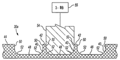
図3は単一半体30aの断面図であり、それはカッター54によって機械加工されている。各キャビティ40は対向する壁内面50間に床48を有するが、この壁のいくつかがリブ42を形成する。各キャビティ40はさらに、壁内面50と床48との間に丸みを付けた移行部52を含む。図示するように、床48および両方の壁内面50は、好ましくは、カッター54の一度の通過によって同時にカットされる。キャビティ40は連続しておりかつリブ42は交差していないので、各キャビティ40は単一のカッターを用いて、その一度の通過によって形成される。これに代えて、キャビティ40はそれぞれ一度の大雑把なカットおよび第2の仕上げカットによって形成されてもよい。これは、カット数および必要なカッターの数を依然として著しく低減する。さらに、床半径は比較的大きく、しかもそれは概ね外面の湾曲をたどるので、カッター54は、これまで必要とされていた5軸マシンの代わりに3軸マシン55(概念的に示す)によって操作できる。さらに、リブ42と交差する横断的に延在するリブが存在しないので、必要とされる直径の異なるカッターの数が大幅に低減される。単一半体は、荒削りおよび最終処理の両方について、単一形態のカッターで仕上げることができる。もう一方のファンブレード単一半体30bも同様の手法にて製造されることになる。
FIG. 3 is a cross-sectional view of a
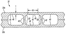
図4はファンブレード30の一部の断面図である。ファンブレード単一半体30aのリブ42は、ファンブレード単一半体30bのリブ42と整列すると共にそれと接合されている。成形中および使用中の強度増強のため、リブ42はテーパー状とされ、かつ伝統的なアーチ形デザイン構成要素を擬する複合半径(丸み52および床48を含む)へと移行する。(丸み52および床48の)二つの半径は、互いの間の移行部およびテーパー状壁のジオメトリーがスムーズかつ緩やかなものとなるよう選定されるべきである。サイジング(sizing)は、推移しかつ耐性(capabilities)を支える必要負荷に依存する。好ましくは、突き出したリブ壁隅肉におけるキャビティ幅wの、床48の厚みtに対する比率は、10よりも小さなものとなるべきである。だが、リブを荷重に対して一層平行に整列させることができる場合、この比率はより大きなものとすることができる。
FIG. 4 is a sectional view of a part of the
半体30a,30bが接合された後、ファンブレード30には、成形処理によって翼形状が付与されるが、これは図5〜図9に示す。成形作業の間、二つの単一半体は、高温下で所望の形状となるようねじられ、そして湾曲させられる。間隔と共に、説明しかつ図示するようなリブ42の向きおよび形状によって、キャビティ40は、成形作業中に、その強度を増大させかつキャビティが潰れるのを抑止するための高圧ガスを必要としない。これによって成形作業の時間および費用が節減される。
After the
図5は図4の組み立てられたファンブレード30の背面図であり、ファンブレード30を通る2本の切断線aおよびbを示している。図6は、図5のファンブレードの拡大上面側斜視図である。図6から分かるように切断線は、概して先端34および前縁36のコーナーの付近のポジションから後縁38に向かって後方に、そして根縁部32に向かって下方に延在する(図5)。切断線a,bは、リブ42およびキャビティ40に対するファンブレード30のねじりおよび湾曲を視覚化するのを助ける。
FIG. 5 is a rear view of the assembled
図7は成形作業後の図4のファンブレードの正面図であり、断面aおよびbの最終位置を示している。図8は図7のファンブレードの上側部分の拡大図である。図9は図7のファンブレードの上面図である。図7ないし図9に関して参照図5から分かるように、リブ42の向きは、予備成形および最終成形作業の間に成形負荷によって生じる負荷ベクトルと平行平面内に存在するべきである。この向きは負荷支持能力のための最適形状を提供し、そして圧縮応力はリブ42へと伝わり、凹状および凸状外皮には残留しない。それゆえリブ42の具体的な向きはファンブレード30の最終的な形状に依存し、これはあるエンジンと他のものとでは異なる。明らかに、ここで説明したさまざまな要求の間には、トレードオフと釣り合いが存在する。たとえば、リブ42は必ずしも完全に負荷ベクトルと平行平面内に存在するとは限らない。こうした理由から、リブを全体的に直線状とすることは回避される。
FIG. 7 is a front view of the fan blade of FIG. 4 after the molding operation and shows the final positions of the cross sections a and b. FIG. 8 is an enlarged view of the upper portion of the fan blade of FIG. FIG. 9 is a top view of the fan blade of FIG. As can be seen from the reference FIG. 5 with respect to FIGS. This orientation provides an optimal shape for load bearing capacity, and compressive stress is transferred to the
図10はファンブレード単一半体60aの第2実施形態を示し、これは図1のタービンエンジン10で使用可能である。繰り返すが、もう一方のファンブレード単一半体(図示せず)は相補的なものとなる。ファンブレード単一半体60aは基板61(好ましくはチタニウム製)を具備し、これは先端64の反対側に存在する根縁部62および後縁68の反対側に存在する前縁66を具備する。複数の長尺な連続キャビティ70は、図3および図4に関連して上で説明した手法で、基板61の内側面に、機械加工によって、あるいは超塑性的にまたは別の方法で形成される。キャビティ70は、複数の連続する非交差リブ72,73を形成するために互いに間隔が置かれる。この実施形態では、リブ間の間隔は全体にわたって一定に保たれる。
FIG. 10 shows a second embodiment of a fan blade
第2実施形態においてキャビティ70a〜70dは、リブ72a〜72eおよびリブ73と並んで連続的に延在する。キャビティ70a〜70dはまた、リブ72a〜72eのいくつかのものの独立(freestanding)端部74の周りを囲むように延びる。これによってキャビティ70a〜70dの数が低減される。
In the second embodiment, the
ファンブレード単一半体60aは領域Aを含み、これは概ね半径方向の中心側半分である。領域Bは概ね前縁66および先端64に隣接する四半分からなる。領域Cは概ね後縁68および先端64に隣接する四半分からなる。移行領域は、領域A,BおよびC間に実質的に形成された中央領域である。
Fan blade
キャビティ70aおよびリブ72aの第1の部分集合体は、根縁部62から領域Aにおいて初め半径方向外側に連続的に延在し、続いて実質的に45度の角度で、ただし領域Bの湾曲経路内を前縁36に向かって湾曲する。領域Bにおいては、各キャビティ70aはリブ72aの一つの独立端部74の周りを囲むよう連続的に延びており、これによってキャビティ70aの数が削減される。リブ73は根縁部62から前縁66まで隣接キャビティ70a間でリブ72aと平行に連続的に延在する。
The first subset of
キャビティ70bおよびリブ72bの第2の部分集合体は、根縁部62から後縁68に隣接する領域Aにおいて初め半径方向外側に先端64に向かって連続的に延在し、続いて移行領域において前縁66に向かってわずかに湾曲し、続いて概ね45度の角度で領域Cのわずかに湾曲した経路内を後縁38に向かって湾曲する。各キャビティ70bもまた、リブ72bの一つの独立端部74の周りを囲むよう連続的に延びており、これによってキャビティ70bの数が削減される。リブ73は隣接キャビティ70b間に形成されると共にリブ72bに対して平行である。
A second subset of
リブ72cの第3の部分集合体は前縁66から後縁68に向かって延在し、かつ領域Bにおける湾曲経路内をわずかに根縁部62に向かって下向きに湾曲する。少なくとも一つのキャビティ70cが、一つのリブ72cの一つの自由端部74をまわり、次のリブ72cの反対側の自由端部74をまわり、そして再び次のリブ72cの反対側の自由端部74をまわる蛇行経路内を連続的に延在する。この蛇行経路もまた、リブ72を形成するために必要なキャビティ70の数をさらに削減する。
The third subset of ribs 72c extends from the leading
リブ72dの第4の組はそれぞれ少なくとも部分的に単一のキャビティ70dによって形成される。キャビティ70dおよびリブ72dは、領域Aにおいて、根縁部62から半径方向外側に(先端64に向かって)連続的に延在し、続いて移行領域において前縁66に向かってわずかに湾曲し、続いて領域Cにおいて概ね60度の角度で後縁68に向かってわずかに湾曲する。先端64付近では、キャビティ70dはリブ72dの自由端部74の周りを囲むように、続いて先端64に向かって概ね60度をなす二つ以上のリブ72dの互い違いの自由端部74の周りを囲むように連続的に延在する。キャビティ70dは続いて、リブ72cと実質的に平行に方向付けられた、すなわち実質的に翼弦方向に概ね30度でかつわずかに湾曲する複数のリブ72eの互い違いの自由端部74の周りを囲むよう領域B内へと連続的に延在する。キャビティ70dのこの長尺な蛇行経路はさらに、リブ72を形成するのに必要なキャビティ70の数を削減する。
Each fourth set of
繰り返すが、領域Aは著しいブレード引っ張り領域である。領域Aにおけるリブ72a,72b,72dの部分は、ブレード半体60aに作用する荷重を支えるのを助ける。リブ72a,72b,72dの半径方向延在部分はさらに、隅肉による応力集中を最小限に抑える。領域Bにおけるリブ72a,72c,72dの部分の実質的に翼弦方向の向きは、鳥の衝突に耐える強度を提供する。領域Cにおけるリブ72b,72dの部分の実質的に半径方向の向きは、先端がファンハウジングの内面を擦る場合に、この先端に強度を付与する。
Again, region A is a significant blade pull region. The portions of
リブ72の独立端部74の周りを囲むよう連続したキャビティ70を機械加工によって形成することにより、必要となるキャビティ70の数はより少なくなり、これによって時間および費用が削減される。だが、リブ72の独立端部74は剛性に変化を引き起こすことがあり、これは、たとえば鳥の衝突、またはブレードが外れたとき脱落した隣接ブレードによる大きな曲げモーメントによりブレードが外的荷重を受けた場合に応力集中を引き起こすことがある。それゆえ図11には、図10の単一半体60a用の代替リブ72’を拡大して示す。代替リブ72’はまた、相補的な単一半体(図示せず)においても使用されることになる。代替リブ72’は独立端部74’を有し、これはリブ72’の残部よりも大きな幅を有するよう拡幅されている。キャビティ70は、リブ72’の自由な拡幅端部74’の周りを囲むよう連続的に延在する。リブ72’はテーパー状となっており、しかも床78へと移り変わる丸み82を有する。丸み82は拡幅端部74’の周りを囲むよう延在する。隣接キャビティ70間のリブ73’は概して一定幅を有する。拡幅端部74’はその位置で接合ジョイントの強度を増大させる。それはまた、隅肉の基部においてフットプリント(footprint)を増大させ、これは拡幅端部74’の近傍における剛性を高め、これによって接合ジョイントに作用する負荷が低減される。
By machining
カッターおよびキャビティ70の幅を変更するのは現実的ではないので、図12には拡幅端部74’を備えた複数のリブ72’の一つの可能な配置構成を示す。キャビティ70の端部が図12に示すように互い違いに配置できる場合には、拡幅端部74’を組み込むことは、重量への影響を最小限に抑えて実現可能である。図12において、リブ72’、およびリブ72’の拡幅端部74’の周りを囲むよう連続的に延在するキャビティ70は、あるリブ72’の拡幅端部74’の増大した幅が隣接リブ72’の拡幅端部74’と整列しないよう互い違いに配置される(リブ72’と直交する方向における「アラインメント」参照)。端部74’を互い違いに配置するには、リブ72’を傾斜させるのがよい手法である。
Since changing the width of the cutter and
互い違い配置が実現可能でない場合には、厚みの変化が緩やかであることが必要となり、あるいは図13に示すように一続きの隣接するものへと曲げられる。図13においては、拡幅端部74’、リブ72’およびキャビティ70は互い違いに配置されておらず、整列している。この場合、拡幅端部74’における厚みの増大は、隣接キャビティ70間の隣接リブ73”における厚みの低減によって相殺される。
If the staggered arrangement is not feasible, the change in thickness needs to be gradual or bent into a series of adjacent ones as shown in FIG. In FIG. 13, the widened ends 74 ', ribs 72' and
特許法および法律学の規定によれば、上記代表的な形態は発明の好ましい実施形態を提示するものと考えられる。だが本発明は、その精神または範囲から逸脱することなく、具体的に図示しかつ説明した以外の方法でも実施できるということに留意すべきである。方法の請求項におけるステップの文字数字式識別子は従属請求項による引用を容易にするためのものであり、別に言及しない限り必須の順序を示すものではない。 According to patent law and legal stipulations, the above representative forms are considered to present preferred embodiments of the invention. However, it should be noted that the invention can be practiced otherwise than as specifically illustrated and described without departing from its spirit or scope. The alphanumeric identifiers of the steps in the method claims are for ease of citation by the dependent claims and do not indicate the required order unless otherwise stated.
10 ガスタービンエンジン
12 エンジン中心線
14 ファン
16 コンプレッサー
18 燃焼セクション
20 タービン
22 ローター
24 ブレード
26 ベーン
27 ファンケース
28 ホットガス流動流
29 ローターディスク
30 ファンブレード
30a 第1の中空ファンブレード単一半体
30b 第2の中空ファンブレード単一半体
31 基板
32 根縁部
34 先端
36 前縁
38 後縁
40a〜40d キャビティ
42a〜42d リブ
44 フレーム
48 床
50 壁内面
54 カッター
55 3軸マシン
60a ファンブレード単一半体
61 基板
62 根縁部
64 先端
66 前縁
68 後縁
70a〜70d キャビティ
72,73 非交差リブ
72’ 代替リブ
72a〜72e,73’ リブ
73” 隣接リブ
74 独立端部
74’ 拡幅端部
78 床
82 丸み
10
74 Independent end 74 '
Claims (17)
前記基板に形成された複数のテーパー状リブであって、それぞれがキャビティに隣接し、前記キャビティ内でテーパーから複合半径へと移り変わる複数のテーパー状リブと、
を備え、
前記複数のリブは、前記基板の根縁部から前記基板の前縁に向かって延びるリブの部分集合体を含むことを特徴とする中空ファンブレード半体。 And Neen portion, a substrate having a tip, a located on opposite sides spaced radially outward from the root edge, further comprising a leading edge located on the opposite side of the trailing edge, said front The edge is spaced apart from the trailing edge in the chord direction; and
A plurality of tapered ribs formed on the substrate, each adjacent to the cavity, a plurality of tapered ribs transitory from taper to compound radius in the cavity,
Equipped with a,
Wherein the plurality of ribs are hollow fan blade halves, characterized in that the Neen portion of the substrate including a rib portion assembly extending toward the front edge of the substrate.
a)第1の基板に複数のリブを形成するステップであって、前記第1の基板が前記複数のリブの各々の両側にキャビティを備える、リブ形成ステップと、
b)中空のファンブレードを形成するように、前記第1の基板における前記複数のリブを第2の基板に接合接触させるステップと、
c)前記キャビティ内の圧力が実質的に雰囲気圧力である状態で、前記中空ファンブレードを翼形状へと成形するステップと、
を含み、
前記成形ステップ(c)は、前記基板の根縁部から前記基板の前縁に向かって延びる前記複数の連続するキャビティの少なくとも一つの部分集合体を形成するステップを含むことを特徴とする中空ファンブレード製造方法。 A method of manufacturing a hollow fan blade,
a) a step of forming a plurality of ribs on the first substrate, the first substrate is provided with cavities on both sides of each of the plurality of ribs, and rib forming step,
b) to form a hollow fan blade, comprising the steps of bonding contact with the plurality of ribs in the first substrate to the second substrate,
c) forming the hollow fan blade into a blade shape with the pressure in the cavity being substantially atmospheric pressure;
Including
The forming step (c) includes forming at least one subset of the plurality of continuous cavities extending from a base edge of the substrate toward a front edge of the substrate. Blade manufacturing method.
Applications Claiming Priority (1)
| Application Number | Priority Date | Filing Date | Title |
|---|---|---|---|
| US10/765,593 US7052238B2 (en) | 2004-01-26 | 2004-01-26 | Hollow fan blade for gas turbine engine |
Publications (2)
| Publication Number | Publication Date |
|---|---|
| JP2005264928A JP2005264928A (en) | 2005-09-29 |
| JP4109261B2 true JP4109261B2 (en) | 2008-07-02 |
Family
ID=34634637
Family Applications (1)
| Application Number | Title | Priority Date | Filing Date |
|---|---|---|---|
| JP2005017037A Active JP4109261B2 (en) | 2004-01-26 | 2005-01-25 | Hollow fan blades for gas turbine engines |
Country Status (5)
| Country | Link |
|---|---|
| US (1) | US7052238B2 (en) |
| EP (2) | EP1982791B1 (en) |
| JP (1) | JP4109261B2 (en) |
| AT (1) | ATE401161T1 (en) |
| DE (1) | DE602005008119D1 (en) |
Families Citing this family (15)
| Publication number | Priority date | Publication date | Assignee | Title |
|---|---|---|---|---|
| US7458780B2 (en) * | 2005-08-15 | 2008-12-02 | United Technologies Corporation | Hollow fan blade for gas turbine engine |
| US7993105B2 (en) * | 2005-12-06 | 2011-08-09 | United Technologies Corporation | Hollow fan blade for gas turbine engine |
| US8257035B2 (en) * | 2007-12-05 | 2012-09-04 | Siemens Energy, Inc. | Turbine vane for a gas turbine engine |
| US20110211965A1 (en) * | 2010-02-26 | 2011-09-01 | United Technologies Corporation | Hollow fan blade |
| US8562286B2 (en) * | 2010-04-06 | 2013-10-22 | United Technologies Corporation | Dead ended bulbed rib geometry for a gas turbine engine |
| FR2978196B1 (en) | 2011-07-20 | 2016-12-09 | Snecma | TURBOMACHINE AUB COMPRISING A PLATE REPORTED ON A MAIN PART |
| US8807925B2 (en) * | 2011-09-23 | 2014-08-19 | United Technologies Corporation | Fan blade having internal rib break-edge |
| US8801367B2 (en) * | 2011-09-23 | 2014-08-12 | United Technologies Corporation | Hollow fan blade channel configuration to reduce stress |
| US8807924B2 (en) * | 2011-09-23 | 2014-08-19 | United Technologies Corporation | Fan blade channel termination |
| US9587492B2 (en) | 2012-05-04 | 2017-03-07 | General Electric Company | Turbomachine component having an internal cavity reactivity neutralizer and method of forming the same |
| US9169731B2 (en) | 2012-06-05 | 2015-10-27 | United Technologies Corporation | Airfoil cover system |
| ITCO20120059A1 (en) * | 2012-12-13 | 2014-06-14 | Nuovo Pignone Srl | METHODS FOR MANUFACTURING SHAPED SHAPED LOAFERS IN 3D OF TURBOMACCHINE BY ADDITIVE PRODUCTION, TURBOMACCHINA CAVE BLOCK AND TURBOMACCHINE |
| CN105736462B (en) * | 2014-12-12 | 2018-03-06 | 中国航发商用航空发动机有限责任公司 | hollow blade and aero-engine |
| CN106126843B (en) * | 2016-06-28 | 2019-08-30 | 明阳智慧能源集团股份公司 | A kind of Bladed blower load processing system based on Matlab |
| CN111535870B (en) * | 2020-05-06 | 2022-08-05 | 北京南方斯奈克玛涡轮技术有限公司 | Engine turbine intermediate supporting device containing hollowed-out fins and manufactured in additive mode |
Family Cites Families (10)
| Publication number | Priority date | Publication date | Assignee | Title |
|---|---|---|---|---|
| US3017159A (en) * | 1956-11-23 | 1962-01-16 | Curtiss Wright Corp | Hollow blade construction |
| US3628226A (en) * | 1970-03-16 | 1971-12-21 | Aerojet General Co | Method of making hollow compressor blades |
| FR2516165B1 (en) * | 1981-11-10 | 1986-07-04 | Snecma | GAS TURBINE BLADE WITH FLUID CIRCULATION COOLING CHAMBER AND METHOD FOR PRODUCING THE SAME |
| US5099573A (en) * | 1990-06-27 | 1992-03-31 | Compressor Components Textron Inc. | Method of making hollow articles |
| US5246340A (en) * | 1991-11-19 | 1993-09-21 | Allied-Signal Inc. | Internally cooled airfoil |
| US5269058A (en) * | 1992-12-16 | 1993-12-14 | General Electric Company | Design and processing method for manufacturing hollow airfoils |
| US5820338A (en) * | 1997-04-24 | 1998-10-13 | United Technologies Corporation | Fan blade interplatform seal |
| US5836744A (en) * | 1997-04-24 | 1998-11-17 | United Technologies Corporation | Frangible fan blade |
| US6637186B1 (en) * | 1997-11-11 | 2003-10-28 | United Technologies Corporation | Fan case liner |
| US6607355B2 (en) * | 2001-10-09 | 2003-08-19 | United Technologies Corporation | Turbine airfoil with enhanced heat transfer |
-
2004
- 2004-01-26 US US10/765,593 patent/US7052238B2/en active Active
-
2005
- 2005-01-24 EP EP08012586A patent/EP1982791B1/en active Active
- 2005-01-24 EP EP05250320A patent/EP1557529B1/en active Active
- 2005-01-24 AT AT05250320T patent/ATE401161T1/en not_active IP Right Cessation
- 2005-01-24 DE DE602005008119T patent/DE602005008119D1/en active Active
- 2005-01-25 JP JP2005017037A patent/JP4109261B2/en active Active
Also Published As
| Publication number | Publication date |
|---|---|
| US7052238B2 (en) | 2006-05-30 |
| JP2005264928A (en) | 2005-09-29 |
| US20050163620A1 (en) | 2005-07-28 |
| EP1557529B1 (en) | 2008-07-16 |
| DE602005008119D1 (en) | 2008-08-28 |
| EP1982791A2 (en) | 2008-10-22 |
| EP1557529A2 (en) | 2005-07-27 |
| EP1982791B1 (en) | 2012-12-05 |
| ATE401161T1 (en) | 2008-08-15 |
| EP1557529A3 (en) | 2006-01-18 |
| EP1982791A3 (en) | 2011-09-28 |
Similar Documents
| Publication | Publication Date | Title |
|---|---|---|
| JP4125725B2 (en) | Hollow fan blades for gas turbine engines | |
| JP4109261B2 (en) | Hollow fan blades for gas turbine engines | |
| JP4166223B2 (en) | Hollow fan blades for gas turbine engines | |
| JP4125726B2 (en) | Hollow fan blades for gas turbine engines | |
| JP4102806B2 (en) | Hollow fan blades for gas turbine engines | |
| US7993105B2 (en) | Hollow fan blade for gas turbine engine | |
| US7458780B2 (en) | Hollow fan blade for gas turbine engine | |
| US7887299B2 (en) | Rotary body for turbo machinery with mistuned blades | |
| JP2001082388A (en) | Plastic molding hybrid blade part | |
| US6705011B1 (en) | Turbine element manufacture | |
| US10920594B2 (en) | Modal response tuned turbine blade |
Legal Events
| Date | Code | Title | Description |
|---|---|---|---|
| RD04 | Notification of resignation of power of attorney |
Free format text: JAPANESE INTERMEDIATE CODE: A7424 Effective date: 20050805 |
|
| A131 | Notification of reasons for refusal |
Free format text: JAPANESE INTERMEDIATE CODE: A131 Effective date: 20070925 |
|
| A521 | Request for written amendment filed |
Free format text: JAPANESE INTERMEDIATE CODE: A523 Effective date: 20071217 |
|
| TRDD | Decision of grant or rejection written | ||
| A01 | Written decision to grant a patent or to grant a registration (utility model) |
Free format text: JAPANESE INTERMEDIATE CODE: A01 Effective date: 20080311 |
|
| A61 | First payment of annual fees (during grant procedure) |
Free format text: JAPANESE INTERMEDIATE CODE: A61 Effective date: 20080403 |
|
| FPAY | Renewal fee payment (event date is renewal date of database) |
Free format text: PAYMENT UNTIL: 20110411 Year of fee payment: 3 |
|
| R150 | Certificate of patent or registration of utility model |
Ref document number: 4109261 Country of ref document: JP Free format text: JAPANESE INTERMEDIATE CODE: R150 Free format text: JAPANESE INTERMEDIATE CODE: R150 |
|
| FPAY | Renewal fee payment (event date is renewal date of database) |
Free format text: PAYMENT UNTIL: 20120411 Year of fee payment: 4 |
|
| R250 | Receipt of annual fees |
Free format text: JAPANESE INTERMEDIATE CODE: R250 |
|
| FPAY | Renewal fee payment (event date is renewal date of database) |
Free format text: PAYMENT UNTIL: 20120411 Year of fee payment: 4 |
|
| FPAY | Renewal fee payment (event date is renewal date of database) |
Free format text: PAYMENT UNTIL: 20130411 Year of fee payment: 5 |
|
| R250 | Receipt of annual fees |
Free format text: JAPANESE INTERMEDIATE CODE: R250 |
|
| FPAY | Renewal fee payment (event date is renewal date of database) |
Free format text: PAYMENT UNTIL: 20130411 Year of fee payment: 5 |
|
| FPAY | Renewal fee payment (event date is renewal date of database) |
Free format text: PAYMENT UNTIL: 20140411 Year of fee payment: 6 |
|
| R250 | Receipt of annual fees |
Free format text: JAPANESE INTERMEDIATE CODE: R250 |
|
| R250 | Receipt of annual fees |
Free format text: JAPANESE INTERMEDIATE CODE: R250 |
|
| R250 | Receipt of annual fees |
Free format text: JAPANESE INTERMEDIATE CODE: R250 |
|
| R250 | Receipt of annual fees |
Free format text: JAPANESE INTERMEDIATE CODE: R250 |
|
| S531 | Written request for registration of change of domicile |
Free format text: JAPANESE INTERMEDIATE CODE: R313531 |
|
| R350 | Written notification of registration of transfer |
Free format text: JAPANESE INTERMEDIATE CODE: R350 |
|
| R250 | Receipt of annual fees |
Free format text: JAPANESE INTERMEDIATE CODE: R250 |
|
| R250 | Receipt of annual fees |
Free format text: JAPANESE INTERMEDIATE CODE: R250 |
|
| R250 | Receipt of annual fees |
Free format text: JAPANESE INTERMEDIATE CODE: R250 |
|
| R250 | Receipt of annual fees |
Free format text: JAPANESE INTERMEDIATE CODE: R250 |
|
| S533 | Written request for registration of change of name |
Free format text: JAPANESE INTERMEDIATE CODE: R313533 |
|
| R350 | Written notification of registration of transfer |
Free format text: JAPANESE INTERMEDIATE CODE: R350 |